Yayınlandı:
9 Nisan 2015
Kategori: Kataloglar
Alışveriş Sepeti
Şu anda ödeme için uygun ürününüz bulunmamaktadır.
Distribütör Seçimi
Alışveriş sepetiniz için kullanmak istediğiniz distribütörü seçin.
Distribütör

09_CA08103002Z
09_CA08103002Z
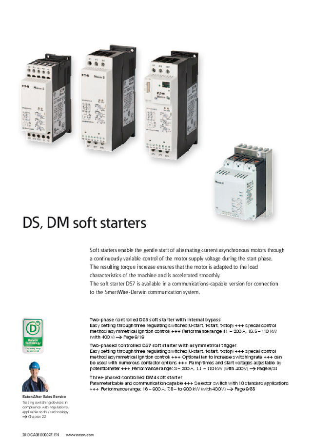
2010 CA08103002Z-EN www.eaton.com Two-phase controlled DS6 soft starter with internal bypass Easy setting through three regulating switches(U-start, t-start, t-stop) +++ special control method (asymmetrical ignition control) +++ Performance range 41 – 200 A, 18.5 – 110 kW (with 400 V) → Page 9/19Two-phased controlled DS7 soft starter with asymmetrical trigger Easy setting through three regulating switches(U-start, t-start, t-stop) +++ special control method (asymmetrical ignition control) +++ Optional fan to increase switching rate +++ can be used with numerous contactor options +++ Ramp times and start voltages adjustable by potentiometer +++ Performance range: 3 – 200 A, 1.1 – 110 kW (with 400 V) → Page 9/31Three-phased controlled DM4 soft starter Parameterizable and communication-capable +++ Selector switch with 10 standard applications +++ Performance range: 16 – 900 A, 7.5 – to 900 kW (with 400 V) → Page 9/55 Soft starters enable the gentle start of alternating current asynchronous motors through a continuously variable control of the motor supply voltage during the start phase. The resulting torque increase ensures that the motor is adapted to the load characteristics of the machine and is accelerated smoothly.The soft starter DS7 is available in a communications-capable version for connection to the SmartWire-Darwin communication system. DS, DM soft starters Eaton After Sales ServiceTesting switching devices in compliance with regulations applicable to this technology → Chapter 22
130 45 95 35 M4 125 122 DS, DM soft starters Technical overview DS6, DS7, DM4 soft starters 9/2 Description DS6, DS7 key to part numbers 9/3 DM4 key to part numbers 9/4 DS6 soft starters System overview DS6 soft starters 9/5 Description DS6 soft starters 9/6 Ordering DS6 soft starters 9/7 DS6 accessories 9/8 Engineering Connection examples 9/10 Assigned switching and protective elements DS6 9/11 Technical data DS6 soft starters 9/12 Dimensions DS6 soft starters 9/14 Fuse base, fuses 9/63 DS7 soft starter System overview DS7 soft starters 9/16 Description DS7 soft starters 9/18 Ordering DS7 soft starters 9/19 DS7 accessories 9/21 Engineering Design with different load cycles 9/25 Potentiometer settings 9/26 LED and operation 9/39 Connection examples 9/27 Assigned switching and protective elements DS7 9/28 Technical data DS7 soft starters 9/32 Dimensions DS7 soft starters 9/38 Fuse bases, fuses 9/63 DM4 soft starters System overview DM4 soft starters 9/39 Description DM4 soft starters 9/40 DE4... accessories 9/41 Ordering DM4 soft starters 9/43 DE4... accessories 9/44 Engineering Connection examples Inline/delta connection 9/46 Soft starters with separate mains contactor 9/47 Bypass circuit 9/48 Soft starters with reversing circuit 9/49 Assigned switching and protective elements DM4 Short start-up time 9/50 Long start-up time 9/52 Technical data DM4 soft starters 9/54 Dimensions DM4 soft starters 9/62 Fuse bases, fuses 9/63 Soft starters
9/2 DS6, DS7, DM4 soft starters 2010 CA08103002Z-EN www.eaton.com Technical overview DS6, DS7, DM4 DS6-340-…-MX DS7-34…SX… DM4-340-… Power section Thyristors in two phases Thyristors in two phases Thyristors in three phases Mains supply voltage U LN 230 - 460 V ±15 % 230 - 480 V ±10 % 230 - 460 V ±15 % Supply voltage 24 V DC 24 V AC/DC, 110/230 V AC 24 V DC, 110 - 230 V AC Mains frequency 45 - 65 Hz ±0 % 45 - 65 Hz ±0 % 45 - 65 Hz ±0 % Rated operational current I e Heating load AC 51 – – – Motor load AC 53 41 - 196 A 3 - 200 A 16 - 900 A Assigned motor rating at 400 V 18.5 - 110 kW 1.1 - 110 kW 7.5 - 500 kW, 11 - 900 kW Overload cycle 10 starts per h with 3 x I N for 5 s 10 starts per h with 3 x I N for 5 s 10 starts per h at 3.5 × I N for 35 s (up to part no. ... 90K) Operating temperature 0 - 40 °C 0 - 40 °C 0 - 40 °C Storage temperature -25 - +55 °C -25 - +55 °C -25 - +55 °C Installation altitude Up to 1000 m a.s.l., over 1000 m with reduced current (2.5 % per 100 m) Up to 1000 m a.s.l., over 1000 m with reduced current (2.5 % per 100 m) Up to 1000 m a.s.l., over 1000 m with reduced current (2.5 % per 100 m) Protection type IP20 IP20 IP20 Changeover time for reversing contactors (transition from 100 % FWD to 100 % REV) – – – Fields of application Three-phase resistive and inductive loads – – ● Three-phase motors ● ● ● Functions Fast and silent switching (semiconductor contactor) – – – Soft start/Soft stop ● ● ● Reversing function - - – Suppression of DC components on motors ● ● ● Potential isolation between power section and control section ● ● ● Internal bypass ● ● – Product standard, determination IEC/EN 60 947-4-2 IEC/EN 60 947-4-2 IEC/EN 60 947-4-2 Approval, certification UL, CSA, CCC UL, CSA, CCC, Gost, Gost-R UL, cUL Notes The value range specifications for the rated operational current and the assigned motor output within each column refer to the entire group, and not to an individual device.Depending on the specific model, DS7 series soft starters require 24 VDC/VAC or 110/230 VAC as a supply voltage.An Easy200-POW power supply is sufficient for operation (keep the total load in mind!).
DS6, DS7, DM4 soft starters 2010 CA08103002Z-EN www.eaton.com 9/3 Key to part numbers DS6 soft starters DS6-340-22K-MX (example) DS 6 - 3 4 0 - 22K - M X DS 6 3 4 0 – Variable three-digit code – M X DS = Drives soft starters Device series 6 = Generation 6 Number of phases 3 = Three-phase connection Voltage class 4 = 400 V/480 V Version 0 Motor rating (in kW) x(x)(x)Ky xx = Decimal specification, whole-number component, y = decimal place Motor code M = For three-phase AC motors Code for additional functions X = With internal bypass DS7 soft starters DS7-340SX081N0-N (example) DS7 3 4 0 SX 081 N 0 - N DS7 3 4 0 SX Variable three-digit code N 0 – N 2 D D DS7 = Device series, Generation 7 Number of phases 3 = Three-phase mains supply voltage Voltage class 4 = 400 V (380 V – -15 % to 480 V + +10 %) Control voltage supply 0 = 24 V AC/DC2 = 110/230 V ACD = 24 V DC SmartWire-Darwin Device version SX = Standard soft starters with internal bypass Rated operational current Variable magnitude in decimal notation Radio interference suppression filters N = No internal radio interference suppression filter Protection type 0 = IP20 Options N = No optionD = SmartWire-Darwin DS6, DS7, DM4
9/4 DS6, DS7, DM4 soft starters 2010 CA08103002Z-EN www.eaton.com DM4 soft starter DM4-340-200K (example) DM 4 - 3 4 0 - 200 K DM 4 3 4 0 Variable three-digit code K DM = drives, motor controllers Device series 4 = Generation 4 Number of phases 3 = Three-phase connection Voltage class 4 = 400 V/480 V Version 0 Motor rating (in kW) x(x)(x)Ky xx = Decimal specification, whole-number component, y = decimal place Unit K = kW
2010 CA08103002Z-EN www.eaton.com DS6 soft starters 9/5 System overview 3 1 2 Basic devices DS6 soft starters 1 Soft starters for three-phase AC motorsAssigned motor rating: 18.5 to 110 kW at 400 VRated operating voltage: 230 to 480 VAsymmetric trigger control for clearly improved true run behavior(Moeller Patent: PCT/EPOO/12938)Selection data → Engineering - Assigned switching and protective devices.Ordering data → Page 9/7 Add-on functions Superfast semiconductor fuses 3 Fuses for protecting the DS7 soft starters from short-circuits or to achieve type “2” coordination for external surface mountingSelection data → Engineering - Assigned switching and protective devices.Ordering data → Page 9/8 Fuse bases 2 For external surface mounting of the superfast semiconductor fuseSelection data → Engineering - Assigned switching and protective devices.Ordering data → Page 9/8 DS6
2010 CA08103002Z-EN www.eaton.com 9/6 DS6 soft starters Description L1 L2 L3 T1 T2 T3 Application The DS6 series soft starters are intended for three-phase motors with normal operating frequency and a rating range of 22 to 110 kW.A significant reduction of the inrush current for three-phase lamps and heaters (with an ungrounded star point) is achieved by setting a short soft start ramp time (at least 1 s).The special actuation method (asymmetrical trigger phase control) for the soft start function avoids the DC components that would normally occur in two-phase-controlled soft starters. This suppresses the generation of an elliptical rotating field, which would cause uneven motor starting and increase the motor's acceleration phase. The true run behavior of the DS6 is therefore comparable with that of a three-phase-controlled soft starter. Features The soft starter DS6-340-MX is available with a rating of 22 to 110 kW. Starting transients and DC components during startup are effectively suppressed and guarantee even motor starting.The ramp times and the start voltage are adjustable via potentiometers. The time can be adjusted between 1 and 30 s (start) and between 0 and 30 s (stop); the start voltage (i.e. the starting torque) from 30 to 100 % mains voltage.The DS6-340-MX models feature built-in bypass contacts that close automatically at TOR (top-of-ramp) and bypass the built-in thyristors. This function provides radio interference level “B” in continuous operation without additional measures. Typical applications for soft starters • Pump drives: Soft starting prevents sudden pressure surges. The mechanical load on the whole plant is reduced and its service life increases. • Fan drives: Soft starting prevents drive belt slippage and premature wear. This reduces operating costs and extends durability. • Conveyors: The conveyor belt starts up gently instead of with a jerk. The conveyed goods do not fall over, the mechanical stress on the conveyor is reduced and its lifespan increased. Documentation Installation instructionsAWA8250-2330 ManualAWB8250-1346 ("Design of soft starters") Notes:See also Engineering of DS7 Settings for Potentiometer DS6
DS6 soft starters Soft starters 2010 CA08103002Z-EN www.eaton.com 9/7 Soft starters Mains supply voltage (50/60 Hz) Assigned motor rating Rated operational current Part no.Article no. PriceSee price list Std. pack 400 V 480 V (AC-53) U LN P P I e V AC kW HP A DS6 soft starters 230…480 22 30 41 DS6-340-22K-MX103086 1 off 30 40 55 DS6-340-30K-MX103087 37 50 68 DS6-340-37K-MX103088 45 60 81 DS6-340-45K-MX103089 55 75 99 DS6-340-55K-MX103150 75 100 134 DS6-340-75K-MX103151 90 125 161 DS6-340-90K-MX103152 110 150 196 DS6-340-110K-MX103153 Information relevant for export to North America Product Standards IEC/EN 60947-4-2; GB 14048.6; UL 508; CSA-C22.2 No 0-M91; CSA-C22.2 No 14-05 CE marking UL File No. E251034 UL CCN NMFT CSA File No. 012528 CSA Class No. 3211-06 NA Certification UL Listed, CSA certified Suitable for Branch circuits Max. Voltage Rating 480 V Degree of Protection IP20; UL/CSA Type 1 DS6 HPL09007EN
9/8 DS6 soft starters Accessories 2010 CA08103002Z-EN www.eaton.com Accessories Rated operational current Maximum power loss Frame size/inside micrometer For use with Part no.Article no. PriceSee price list Std. pack Information relevant for export to North America P v A W mm Accessories Fuse links 100 22 80 DS6-340-22K-MX 20.282.20-100106654 6 off Product Standards UL 248-13 CE marking UL File No. E180276 UL CCN JFHR2 CSA File No. UL report applies to both US and Canada CSA Class No. JFHR8 NA Certification UL Recog-nized, certified by UL for use in Canada Max. Voltage Rating 660V 125 24 80 DS6-340-30K-MX 20.282.20-125232087 6 off 200 44 80 DS6-340-37K-MXDS6-340-45K-MXDS6-340-55K-MX 20.610.32-200106475 3 off 350 61 80 DS6-340-75K-MX 20.610.32-350221161 2 off 400 70 80 DS6-340-90K-MX 20.610.32-400106476 3 off 500 72 80 DS6-340-110K-MX 20.610.32-500221163 2 off Frame size/inside micrometer For use with Part no.Article no. PriceSee price list Std. pack Information relevant for export to North America mm Fuse bases For semiconductor fuses 80 20.282.20-…20.189.20-… 21.189.01232064 5 off 80 20.6xx.32-… 21.313.02232076 2 off HPL09008EN
DS6 soft starters Accessories 2010 CA08103002Z-EN www.eaton.com 9/9 Accessories Frame size/inside micrometer For use with Part no.Article no. PriceSee price list Std. pack Information relevant for export to North America mm Terminal cover, knockout, no UL/CSA approval For box terminal 1) – NZM1, PN1, N1DS6-340-22K…55K-MX NZM1-XKSFA100780 1 off UL/CSA certification not required Cover 2) – NZM2, PN2, NS2DS6-340-75K…110K NZM2-XKSA260038 1 off Product Standards UL489; CSA-C22.2 No. 5-09; IEC60947, CE marking UL File No. E31593 UL CCN DIHS CSA File No. 22086 CSA Class No. 1432-01 NA Certification UL Listed, CSA certified Suitable for Refer to main component information Terminal cover 1) – NZM2, PN2, N(S)2DS6-340-75K…110K NZM2-XKSFA104640 1 off UL/CSA certification not required IP2X protection against contact with a finger For box terminal 3) – NZM2, PN2, N(S)2DS6-340-75K…110K NZM2-XIPK266773 1 off UL/CSA certification not required IP2X protection against contact with a finger For cover NZM2-XKSA or NZM2 or NZM2...(C)NA und N(S)2...NA 4) – NZM2, PN2, N(S)2 NZM2-XIPA266777 1 off UL/CSA certification not required Notes 1) Type contains parts for a terminal located at top or bottom for 3 or 4-pole switches.Increased protection against direct contact (simplified finger protection). 2) Type contains parts for a terminal located at top or bottom for 3 pole switches.Protection against direct contact where cable lugs, busbars or tunnel terminals are used.When using insulated conductor material to protection type IP1X. 3) Type contains parts for a terminal located at top or bottom for 3 pole switches.Increased protection against direct contact to IP2X.Protection when reaching into the cable connection area with the connection of cables in the box terminal.With two conductors max cross-section 25 mm 2 or AWG4. Cannot be combined with NZM-XSTK control circuit terminal. 4) Type contains parts for a terminal located at top or bottom for 3 or 4-pole switches.Increased protection against direct contact to IP2X.When mounting NZM2-..-(C)NA or NZM...-NA the following applies:With two conductors max cross-section 25 mm 2 or AWG4. HPL09009EN
9/10 DS6 soft starters Connection examples 2010 CA08103002Z-EN www.eaton.com Connection examples Standard connection Direct soft start Soft starters and main switches with EMERGENCY STOP function according to IEC/EN 60204‐1 and VDE 0113-1 Q1: NZM1, NZM2 ① Control circuit terminal ② Undervoltage releases with early-make auxiliary contacts 3 AC, 230 V NZM1-XUHIV208-240ACNZM2/3-XUHIV208-240AC 3 AC, 400 V NZM1-XUHIV380-440ACNZM2/3-XUHIV380-440AC = Emergency switching off M 3 ~ 1L1 3L2 5L3 PE PE 0 V + 24 TOR Ready - A2 EN + A1 13 14 24 + 24 V 23 2T1 4T2 6T3 L1L2L3PE Q1 Q21 F3 M1 I I I Q1 + A1, EN + 24 V Ready (23/24) t - Start U Start TOR (13/14) U T1, T2, T3 U L1, L2, L3 Q1 M 3 ~ 1L1 3L2 5L3 PE PE 0 V D2 D1 3.13 3.14 + 24 TOR Ready - A2 EN + A1 13 14 24 + 24 V 23 2T1 4T2 6T3 L1 L2 L3 PE Q1 Q1 S3 Q21 F3 M1 I U I I b a DS6
DS6 soft starters Assigned switching and protective elements 2010 CA08103002Z-EN www.eaton.com 9/11 Assigned switching and protective elements Assigned motor rating for Rated operational current 1) Part no.Soft starters Soft starter function Semiconductor fuse (optional, in addition to the protective devices for type “1” coordination, required for type “2” coordination) 5) 400 V 480 V Device Motor Cable protection 2) Mains contactor (optional) 3) Overload relays 4) Fuses Fuse holders P P I e I e kW HP A A Type “1” coordination Number x Part no. Number x Part no. Soft starters for three-phase mains connection, low operating frequency, (5 s, 3 x I e , 10 Starts/h) 18.5 25 41 36 DS6-340-22K-MX NZMN1-M40 / PKZM4-40 DILM40 ZB65-40+ZB65-XEZ 2 x 20.282.20-100 3 x 21.189.01 22 30 41 41 DS6-340-22K-MX NZMN1-M50 / PKZM4-50 DILM50 ZB65-40+ZB65-XEZ 3 x 20.282.20-100 3 x 21.189.01 30 40 55 55 DS6-340-30K-MX NZMN1-M63 / PKZM4-58 DILM65 ZB65-57+ZB65-XEZ 3 x 20.282.20-125 3 x 21.189.01 37 50 68 68 DS6-340-37K-MX NZMN1-M80 DILM80 ZB150-100/KK 3 x 20.610.32-200 3 x 21.313.02 45 60 81 81 DS6-340-45K-MX NZMN1-M100 DILM90 ZB150-100/KK 3 x 20.610.32-200 3 x 21.313.02 55 75 99 99 DS6-340-55K-MX NZMN1-M100 DILM115 ZB150-125/KK 3 x 20.610.32-200 3 x 21.313.02 75 100 134 134 DS6-340-75K-MX NZMN2-M160 DILM150 ZB150-150/KK 3 x 20.610.32-350 3 x 21.313.02 90 125 161 160 DS6-340-90K-MX NZMN2-M200 DILM185 Z5-160/FF250 3 x 20.610.32-400 3 x 21.313.02 110 150 196 196 DS6-340-110K-MX NZMN2-M200 DILM225 Z5-160/FF250 3 x 20.610.32-500 3 x 21.313.02 Notes 1) Rated operational current based on the load cycle specified here. 2) Used to specify the circuit-breaker required for the specified load cycle. For other switching cycles (operating frequency, overcurrent, overcurrent time, duty factor), this value changes and must be modified accordingly. The same applies to higher motor currents. 3) A mains contactor is not required. Disconnection characteristics in accordance with VDE can only be ensured with the specified circuit-breaker. 4) An external overload relay is required if the main contacts are not to be disconnected in the event of an overload and a controlled soft stop is desired instead. 5) The superfast semiconductor fuses protect the soft starter from short circuits on the motor side. This cannot prevent damage caused by voltage peaks (e.g. caused by a lightning strike).
9/12 DS6 soft starters Soft starters 2010 CA08103002Z-EN www.eaton.com 2010 CA08103002Z-EN www.eaton.com DS6 soft starters Soft starters Soft starters DS6-340-22K-MX DS6-340-30K-MX DS6-340-37K-MX DS6-340-45K-MX DS6-340-55K-MX DS6-340-75K-MX DS6-340-90K-MX DS6-340-110K-MX General Standards IEC/EN 60947-4-2 IEC/EN 60947-4-2 IEC/EN 60947-4-2 IEC/EN 60947-4-2 IEC/EN 60947-4-2 IEC/EN 60947-4-2 IEC/EN 60947-4-2 IEC/EN 60947-4-2 Approvals – – – – – – – – Climatic proofing Damp heat, constant, according to IEC 60068-2-78, damp heat, cyclic, according to IEC 60068-2-10 Damp heat, constant, according to IEC 60068-2-78, damp heat, cyclic, according to IEC 60068-2-10 Ambient temperature °C 0 - +40, up to 60 at 1 % derating per Kelvin temperature rise 0 - +40, up to 60 at 1 % derating per Kelvin temperature rise 0 - +40, up to 60 at 1 % derating per Kelvin temperature rise 0 - +40, up to 60 at 1 % derating per Kelvin temperature rise 0 - +40, up to 60 at 1 % derating per Kelvin temperature rise 0 - +40, up to 60 at 1 % derating per Kelvin temperature rise 0 - +40, up to 60 at 1 % derating per Kelvin temperature rise 0 - +40, up to 60 at 1 % derating per Kelvin temperature rise Ambient temperature storage °C -25 - 55 -25 - 55 -25 - 55 -25 - 55 -25 - 55 -25 - 55 -25 - 55 -25 - 55 Installation altitude m 0 - 1000, above that 1 % derating per 100 m, to max. 2000 m 0 - 1000, above that 1 % derating per 100 m, to max. 2000 m 0 - 1000, above that 1 % derating per 100 m, to max. 2000 m 0 - 1000, above that 1 % derating per 100 m, to max. 2000 m 0 - 1000, above that 1 % derating per 100 m, to max. 2000 m 0 - 1000, above that 1 % derating per 100 m, to max. 2000 m 0 - 1000, above that 1 % derating per 100 m, to max. 2000 m 0 - 1000, above that 1 % derating per 100 m, to max. 2000 m Mounting position Vertical Vertical Vertical Vertical Vertical Vertical Vertical Vertical Protection type (power terminals) IP20 IP20 IP20 IP20 IP20 IP20 IP20 IP20 Protection against direct contact Finger- and back-of-hand proof Finger- and back-of-hand proof Overvoltage category/pollution degree II/2 II/2 II/2 II/2 II/2 II/2 II/2 II/2 Mechanical shock resistance 8 g/11 ms 8 g/11 ms 8 g/11 ms 8 g/11 ms 8 g/11 ms 8 g/11 ms 8 g/11 ms 8 g/11 ms Vibration resistance to EN 60721-3-2 g 2M2 2M2 2M2 2M2 2M2 2M2 2M2 2M2 Average heat dissipation with nominal load cycle W 7 10 13 18 25 24 30 42 Dimensions (W x H x D) mm 93 x 175 x 139 93 x 175 x 139 93 x 175 x 139 93 x 175 x 139 93 x 175 x 139 108 x 215 x 178 108 x 215 x 178 108 x 215 x 178 Radio interference level A1 A1 A1 A1 A1 A1 A1 A1 Weight kg 1.8 1.8 1.8 1.8 1.8 3.7 3.7 3.7 Main contacts Rated operating voltage U e V AC 230 - 460 230 - 460 230 - 460 230 - 460 230 - 460 230 - 460 230 - 460 230 - 460 Mains frequency Hz 50/60 50/60 50/60 50/60 50/60 50/60 50/60 50/60 Rated operational current Motor load (AC-53) I e A 41 55 68 81 99 134 160 196 Assigned motor rating (standard connection) 230 V P kW 11 15 15 22 30 30 45 55 400 V P kW 22 30 37 45 55 75 90 110 480 V P HP 30 40 50 60 75 100 125 150 Overload cycle to IEC/EN 60947-4-2 AC-53 41 A: AC-53a: 3 - 5; 75 - 10 55 A: AC-53a: 3 - 5; 75 - 10 68 A: AC-53a: 3 - 5; 75 - 10 81 A: AC-53a: 3 - 5; 75 - 10 99 A: AC-53a: 3 - 5; 75 - 10 135 A: AC-53a: 3 - 5; 75 - 10 160 A: AC-53a: 3 - 5; 75 - 10 200 A: AC-53a: 3 - 5; 75 - 10 Terminal capacity Power cables Solid mm 2 1 x (25 - 70)2 x (6 - 25) 1 x (25 - 70)2 x (6 - 25) 1 x (25 - 70)2 x (6 - 25) 1 x (25 - 70)2 x (6 - 25) 1 x (25 - 70)2 x (6 - 25) 1 x (4 - 185)2 x (4 - 70) 1 x (4 - 185)2 x (4 - 70) 1 x (4 - 185)2 x (4 - 70) Flexible with ferrule mm 2 – – – – – – – – Stranded mm 2 1 x (25 - 70)2 x (6 - 25) 1 x (25 - 70)2 x (6 - 25) 1 x (25 - 70)2 x (6 - 25) 1 x (25 - 70)2 x (6 - 25) 1 x (25 - 70)2 x (6 - 25) 1 x (4 - 185)2 x (4 - 70) 1 x (4 - 185)2 x (4 - 70) 1 x (4 - 185)2 x (4 - 70) Solid or stranded AWG 1 x (12 - 2/0) 1 x (12 - 2/0) 1 x (12 - 2/0) 1 x (12 - 2/0) 1 x (12 - 2/0) 1 x (12 - 350 kcmil)2 x (12 - 00) 1 x (12 - 350 kcmil)2 x (12 - 00) 1 x (12 - 350 kcmil)2 x (12 - 00) Flat conductor min. mm 2 x 9 x 0.8 2 x 9 x 0.8 2 x 9 x 0.8 2 x 9 x 0.8 2 x 9 x 0.8 2 x 9 x 0.8 2 x 9 x 0.8 2 x 9 x 0.8 max. mm 9 x 9 x 0.9 9 x 9 x 0.9 9 x 9 x 0.9 9 x 9 x 0.9 9 x 9 x 0.9 10 x 16 x 0.8 10 x 16 x 0.8 10 x 16 x 0.8 Tightening torque Nm – – – – – – – – Control cables Solid mm 2 1 x (0.5 - 2.5)2 x (0.5 - 1.0) 1 x (0.5 - 2.5)2 x (0.5 - 1.0) 1 x (0.5 - 2.5)2 x (0.5 - 1.0) 1 x (0.5 - 2.5)2 x (0.5 - 1.0) 1 x (0.5 - 2.5)2 x (0.5 - 1.0) 1 x (0.5 - 2.5)2 x (0.5 - 1.0) 1 x (0.5 - 2.5)2 x (0.5 - 1.0) 1 x (0.5 - 2.5)2 x (0.5 - 1.0) Flexible with ferrule mm 2 1 x (0.5 - 1.5)2 x (0.5 - 0.75) 1 x (0.5 - 1.5)2 x (0.5 - 0.75) 1 x (0.5 - 1.5)2 x (0.5 - 0.75) 1 x (0.5 - 1.5)2 x (0.5 - 0.75) 1 x (0.5 - 1.5)2 x (0.5 - 0.75) 1 x (0.5 - 1.5)2 x (0.5 - 0.75) 1 x (0.5 - 1.5)2 x (0.5 - 0.75) 1 x (0.5 - 1.5)2 x (0.5 - 0.75) Stranded mm 2 1 x (0.5 - 1.5)2 x (0.5 - 1.0) 1 x (0.5 - 1.5)2 x (0.5 - 1.0) 1 x (0.5 - 1.5)2 x (0.5 - 1.0) 1 x (0.5 - 1.5)2 x (0.5 - 1.0) 1 x (0.5 - 1.5)2 x (0.5 - 1.0) 1 x (0.5 - 1.5)2 x (0.5 - 1.0) 1 x (0.5 - 1.5)2 x (0.5 - 1.0) 1 x (0.5 - 1.5)2 x (0.5 - 1.0) Solid or stranded AWG 1 x (21 - 14)2 x (21 - 18) 1 x (21 - 14)2 x (21 - 18) 1 x (21 - 14)2 x (21 - 18) 1 x (21 - 14)2 x (21 - 18) 1 x (21 - 14)2 x (21 - 18) 1 x (21 - 14)2 x (21 - 18) 1 x (21 - 14)2 x (21 - 18) 1 x (21 - 14)2 x (21 - 18) Flat conductor – – – – – – – – Tightening torque Nm 0.4 0.4 0.4 0.4 0.4 0.4 0.4 0.4 Screwdriver mm 0.6 x 3.5 0.6 x 3.5 0.6 x 3.5 0.6 x 3.5 0.6 x 3.5 0.6 x 3.5 0.6 x 3.5 0.6 x 3.5 9/13 DS6 DS6
9/12 DS6 soft starters Soft starters 2010 CA08103002Z-EN www.eaton.com 2010 CA08103002Z-EN www.eaton.com DS6 soft starters Soft starters Soft starters DS6-340-22K-MX DS6-340-30K-MX DS6-340-37K-MX DS6-340-45K-MX DS6-340-55K-MX DS6-340-75K-MX DS6-340-90K-MX DS6-340-110K-MX General Standards IEC/EN 60947-4-2 IEC/EN 60947-4-2 IEC/EN 60947-4-2 IEC/EN 60947-4-2 IEC/EN 60947-4-2 IEC/EN 60947-4-2 IEC/EN 60947-4-2 IEC/EN 60947-4-2 Approvals – – – – – – – – Climatic proofing Damp heat, constant, according to IEC 60068-2-78, damp heat, cyclic, according to IEC 60068-2-10 Damp heat, constant, according to IEC 60068-2-78, damp heat, cyclic, according to IEC 60068-2-10 Ambient temperature °C 0 - +40, up to 60 at 1 % derating per Kelvin temperature rise 0 - +40, up to 60 at 1 % derating per Kelvin temperature rise 0 - +40, up to 60 at 1 % derating per Kelvin temperature rise 0 - +40, up to 60 at 1 % derating per Kelvin temperature rise 0 - +40, up to 60 at 1 % derating per Kelvin temperature rise 0 - +40, up to 60 at 1 % derating per Kelvin temperature rise 0 - +40, up to 60 at 1 % derating per Kelvin temperature rise 0 - +40, up to 60 at 1 % derating per Kelvin temperature rise Ambient temperature storage °C -25 - 55 -25 - 55 -25 - 55 -25 - 55 -25 - 55 -25 - 55 -25 - 55 -25 - 55 Installation altitude m 0 - 1000, above that 1 % derating per 100 m, to max. 2000 m 0 - 1000, above that 1 % derating per 100 m, to max. 2000 m 0 - 1000, above that 1 % derating per 100 m, to max. 2000 m 0 - 1000, above that 1 % derating per 100 m, to max. 2000 m 0 - 1000, above that 1 % derating per 100 m, to max. 2000 m 0 - 1000, above that 1 % derating per 100 m, to max. 2000 m 0 - 1000, above that 1 % derating per 100 m, to max. 2000 m 0 - 1000, above that 1 % derating per 100 m, to max. 2000 m Mounting position Vertical Vertical Vertical Vertical Vertical Vertical Vertical Vertical Protection type (power terminals) IP20 IP20 IP20 IP20 IP20 IP20 IP20 IP20 Protection against direct contact Finger- and back-of-hand proof Finger- and back-of-hand proof Overvoltage category/pollution degree II/2 II/2 II/2 II/2 II/2 II/2 II/2 II/2 Mechanical shock resistance 8 g/11 ms 8 g/11 ms 8 g/11 ms 8 g/11 ms 8 g/11 ms 8 g/11 ms 8 g/11 ms 8 g/11 ms Vibration resistance to EN 60721-3-2 g 2M2 2M2 2M2 2M2 2M2 2M2 2M2 2M2 Average heat dissipation with nominal load cycle W 7 10 13 18 25 24 30 42 Dimensions (W x H x D) mm 93 x 175 x 139 93 x 175 x 139 93 x 175 x 139 93 x 175 x 139 93 x 175 x 139 108 x 215 x 178 108 x 215 x 178 108 x 215 x 178 Radio interference level A1 A1 A1 A1 A1 A1 A1 A1 Weight kg 1.8 1.8 1.8 1.8 1.8 3.7 3.7 3.7 Main contacts Rated operating voltage U e V AC 230 - 460 230 - 460 230 - 460 230 - 460 230 - 460 230 - 460 230 - 460 230 - 460 Mains frequency Hz 50/60 50/60 50/60 50/60 50/60 50/60 50/60 50/60 Rated operational current Motor load (AC-53) I e A 41 55 68 81 99 134 160 196 Assigned motor rating (standard connection) 230 V P kW 11 15 15 22 30 30 45 55 400 V P kW 22 30 37 45 55 75 90 110 480 V P HP 30 40 50 60 75 100 125 150 Overload cycle to IEC/EN 60947-4-2 AC-53 41 A: AC-53a: 3 - 5; 75 - 10 55 A: AC-53a: 3 - 5; 75 - 10 68 A: AC-53a: 3 - 5; 75 - 10 81 A: AC-53a: 3 - 5; 75 - 10 99 A: AC-53a: 3 - 5; 75 - 10 135 A: AC-53a: 3 - 5; 75 - 10 160 A: AC-53a: 3 - 5; 75 - 10 200 A: AC-53a: 3 - 5; 75 - 10 Terminal capacity Power cables Solid mm 2 1 x (25 - 70)2 x (6 - 25) 1 x (25 - 70)2 x (6 - 25) 1 x (25 - 70)2 x (6 - 25) 1 x (25 - 70)2 x (6 - 25) 1 x (25 - 70)2 x (6 - 25) 1 x (4 - 185)2 x (4 - 70) 1 x (4 - 185)2 x (4 - 70) 1 x (4 - 185)2 x (4 - 70) Flexible with ferrule mm 2 – – – – – – – – Stranded mm 2 1 x (25 - 70)2 x (6 - 25) 1 x (25 - 70)2 x (6 - 25) 1 x (25 - 70)2 x (6 - 25) 1 x (25 - 70)2 x (6 - 25) 1 x (25 - 70)2 x (6 - 25) 1 x (4 - 185)2 x (4 - 70) 1 x (4 - 185)2 x (4 - 70) 1 x (4 - 185)2 x (4 - 70) Solid or stranded AWG 1 x (12 - 2/0) 1 x (12 - 2/0) 1 x (12 - 2/0) 1 x (12 - 2/0) 1 x (12 - 2/0) 1 x (12 - 350 kcmil)2 x (12 - 00) 1 x (12 - 350 kcmil)2 x (12 - 00) 1 x (12 - 350 kcmil)2 x (12 - 00) Flat conductor min. mm 2 x 9 x 0.8 2 x 9 x 0.8 2 x 9 x 0.8 2 x 9 x 0.8 2 x 9 x 0.8 2 x 9 x 0.8 2 x 9 x 0.8 2 x 9 x 0.8 max. mm 9 x 9 x 0.9 9 x 9 x 0.9 9 x 9 x 0.9 9 x 9 x 0.9 9 x 9 x 0.9 10 x 16 x 0.8 10 x 16 x 0.8 10 x 16 x 0.8 Tightening torque Nm – – – – – – – – Control cables Solid mm 2 1 x (0.5 - 2.5)2 x (0.5 - 1.0) 1 x (0.5 - 2.5)2 x (0.5 - 1.0) 1 x (0.5 - 2.5)2 x (0.5 - 1.0) 1 x (0.5 - 2.5)2 x (0.5 - 1.0) 1 x (0.5 - 2.5)2 x (0.5 - 1.0) 1 x (0.5 - 2.5)2 x (0.5 - 1.0) 1 x (0.5 - 2.5)2 x (0.5 - 1.0) 1 x (0.5 - 2.5)2 x (0.5 - 1.0) Flexible with ferrule mm 2 1 x (0.5 - 1.5)2 x (0.5 - 0.75) 1 x (0.5 - 1.5)2 x (0.5 - 0.75) 1 x (0.5 - 1.5)2 x (0.5 - 0.75) 1 x (0.5 - 1.5)2 x (0.5 - 0.75) 1 x (0.5 - 1.5)2 x (0.5 - 0.75) 1 x (0.5 - 1.5)2 x (0.5 - 0.75) 1 x (0.5 - 1.5)2 x (0.5 - 0.75) 1 x (0.5 - 1.5)2 x (0.5 - 0.75) Stranded mm 2 1 x (0.5 - 1.5)2 x (0.5 - 1.0) 1 x (0.5 - 1.5)2 x (0.5 - 1.0) 1 x (0.5 - 1.5)2 x (0.5 - 1.0) 1 x (0.5 - 1.5)2 x (0.5 - 1.0) 1 x (0.5 - 1.5)2 x (0.5 - 1.0) 1 x (0.5 - 1.5)2 x (0.5 - 1.0) 1 x (0.5 - 1.5)2 x (0.5 - 1.0) 1 x (0.5 - 1.5)2 x (0.5 - 1.0) Solid or stranded AWG 1 x (21 - 14)2 x (21 - 18) 1 x (21 - 14)2 x (21 - 18) 1 x (21 - 14)2 x (21 - 18) 1 x (21 - 14)2 x (21 - 18) 1 x (21 - 14)2 x (21 - 18) 1 x (21 - 14)2 x (21 - 18) 1 x (21 - 14)2 x (21 - 18) 1 x (21 - 14)2 x (21 - 18) Flat conductor – – – – – – – – Tightening torque Nm 0.4 0.4 0.4 0.4 0.4 0.4 0.4 0.4 Screwdriver mm 0.6 x 3.5 0.6 x 3.5 0.6 x 3.5 0.6 x 3.5 0.6 x 3.5 0.6 x 3.5 0.6 x 3.5 0.6 x 3.5 9/13 DS6 DS6
9/14 DS6 soft starters Soft starters 2010 CA08103002Z-EN www.eaton.com 2010 CA08103002Z-EN www.eaton.com DS6 soft starters Soft starters Power section Rated impulse withstand voltage1.2 μs/50 μs (pulse rise time/decay time according to IEC/EN 60947-2 and -3)Applies for control circuit/power section/enclosure U imp kV 4 4 4 4 4 4 4 4 Rated insulation voltage U i V AC 500 500 500 500 500 500 500 500 Short-circuit rating Type “1” of coordination at AC-53a: 3…5 : 75…10 NZMN1-M50/PKZM4-50 NZMN1-M63/PKZM4-58 NZMN1-M80 NZMN1-M100 NZMN1-M100 NZMN2-M160 NZMN2-M200 NZMN2-M200 Type “2” of coordination (in addition to the fuses for type of coordination “1”) 3 x 20.282.20-100 3 x 20.282.20-125 3 x 20.610.32-200 3 x 20.610.32-200 3 x 20.610.32-200 3 x 20.610.32-350 3 x 20.610.32-400 3 x 20.610.20-500 Fuse base (number x Part no.) 3 x 21.189.01 3 x 21.189.01 3 x 21.313.02 3 x 21.313.02 3 x 21.313.02 3 x 21.313.02 3 x 21.313.02 3 x 21.313.02 Control circuit Controller supply voltage Voltage V +24 DC +10 %/-15 % +24 DC +10 %/-15 % +24 DC +10 %/-15 % +24 DC +10 %/-15 % +24 DC +10 %/-15 % +24 DC +10 %/-15 % +24 DC +10 %/-15 % +24 DC +10 %/-15 % Current consumption Current consumption at 24 V DC mA 35 35 35 35 35 35 35 35 Current consumption in operation at 24 V DC mA 65 65 65 65 65 65 65 65 Current consumption at peak load (close bypass) at 24 V DC 600/50 ms 600/50 ms 600/50 ms 600/50 ms 600/50 ms 600/50 ms 600/50 ms 600/50 ms Control voltage DC operated V DC +24 +10 %/-15 % +24 +10 %/-15 % +24 +10 %/-15 % +24 +10 %/-15 % +24 +10 %/-15 % +24 +10 %/-15 % +24 +10 %/-15 % +24 +10 %/-15 % Current consumption at 24 V DC mA 14 14 14 14 14 14 14 14 Pick-up voltage DC operated V DC +17.3 - 27 +17.3 - 27 +17.3 - 27 +17.3 - 27 +17.3 - 27 +17.3 - 27 +17.3 - 27 +17.3 - 27 Drop-out voltage DC operated V DC 0 - 3 0 - 3 0 - 3 0 - 3 0 - 3 0 - 3 0 - 3 0 - 3 Pick-up time DC operated ms 250 250 250 250 250 250 250 250 Drop-out time DC operated ms 190 190 190 190 190 190 190 190 Relay outputs Number (top of ramp) 2 (TOR, Ready) 2 (TOR, Ready) 2 (TOR, Ready) 2 (TOR, Ready) 2 (TOR, Ready) 2 (TOR, Ready) 2 (TOR, Ready) 2 (TOR, Ready) Voltage V AC 250 250 250 250 250 250 250 250 Current A 3 3 3 3 3 3 3 3 Soft start function Ramp times Acceleration time s 1 - 30 1 - 30 1 - 30 1 - 30 1 - 30 1 - 30 1 - 30 1 - 30 Deceleration time s 0 - 30 0 - 30 0 - 30 0 - 30 0 - 30 0 - 30 0 - 30 0 - 30 Start voltage (= switch-off voltage) % 30 - 100 30 - 100 30 - 100 30 - 100 30 - 100 30 - 100 30 - 100 30 - 100 Voltage reduction at stop % 8 8 8 8 8 8 8 8 Torque-free time when changing direction of rotation ms – – – – – – – – DS6-340-22K-MX DS6-340-30K-MX DS6-340-37K-MX DS6-340-45K-MX DS6-340-55K-MX DS6-340-75K-MX DS6-340-90K-MX DS6-340-110K-MX Dimensions Dimensions DS6-340-22K-MXDS6-340-30K-MXDS6-340-37K-MXDS6-340-45K-MXDS6-340-55K-MX DS6-340-75K-MXDS6-340-90K-MXDS6-340-110K-MX 161 129 22.5 PE 30 30 22.5 93 e PE e 175 35 139 15 35 35 108 200 158 PE 15 e PE e 215 52.5 178 9/15 DS6 DS6
9/14 DS6 soft starters Soft starters 2010 CA08103002Z-EN www.eaton.com 2010 CA08103002Z-EN www.eaton.com DS6 soft starters Soft starters Power section Rated impulse withstand voltage1.2 μs/50 μs (pulse rise time/decay time according to IEC/EN 60947-2 and -3)Applies for control circuit/power section/enclosure U imp kV 4 4 4 4 4 4 4 4 Rated insulation voltage U i V AC 500 500 500 500 500 500 500 500 Short-circuit rating Type “1” of coordination at AC-53a: 3…5 : 75…10 NZMN1-M50/PKZM4-50 NZMN1-M63/PKZM4-58 NZMN1-M80 NZMN1-M100 NZMN1-M100 NZMN2-M160 NZMN2-M200 NZMN2-M200 Type “2” of coordination (in addition to the fuses for type of coordination “1”) 3 x 20.282.20-100 3 x 20.282.20-125 3 x 20.610.32-200 3 x 20.610.32-200 3 x 20.610.32-200 3 x 20.610.32-350 3 x 20.610.32-400 3 x 20.610.20-500 Fuse base (number x Part no.) 3 x 21.189.01 3 x 21.189.01 3 x 21.313.02 3 x 21.313.02 3 x 21.313.02 3 x 21.313.02 3 x 21.313.02 3 x 21.313.02 Control circuit Controller supply voltage Voltage V +24 DC +10 %/-15 % +24 DC +10 %/-15 % +24 DC +10 %/-15 % +24 DC +10 %/-15 % +24 DC +10 %/-15 % +24 DC +10 %/-15 % +24 DC +10 %/-15 % +24 DC +10 %/-15 % Current consumption Current consumption at 24 V DC mA 35 35 35 35 35 35 35 35 Current consumption in operation at 24 V DC mA 65 65 65 65 65 65 65 65 Current consumption at peak load (close bypass) at 24 V DC 600/50 ms 600/50 ms 600/50 ms 600/50 ms 600/50 ms 600/50 ms 600/50 ms 600/50 ms Control voltage DC operated V DC +24 +10 %/-15 % +24 +10 %/-15 % +24 +10 %/-15 % +24 +10 %/-15 % +24 +10 %/-15 % +24 +10 %/-15 % +24 +10 %/-15 % +24 +10 %/-15 % Current consumption at 24 V DC mA 14 14 14 14 14 14 14 14 Pick-up voltage DC operated V DC +17.3 - 27 +17.3 - 27 +17.3 - 27 +17.3 - 27 +17.3 - 27 +17.3 - 27 +17.3 - 27 +17.3 - 27 Drop-out voltage DC operated V DC 0 - 3 0 - 3 0 - 3 0 - 3 0 - 3 0 - 3 0 - 3 0 - 3 Pick-up time DC operated ms 250 250 250 250 250 250 250 250 Drop-out time DC operated ms 190 190 190 190 190 190 190 190 Relay outputs Number (top of ramp) 2 (TOR, Ready) 2 (TOR, Ready) 2 (TOR, Ready) 2 (TOR, Ready) 2 (TOR, Ready) 2 (TOR, Ready) 2 (TOR, Ready) 2 (TOR, Ready) Voltage V AC 250 250 250 250 250 250 250 250 Current A 3 3 3 3 3 3 3 3 Soft start function Ramp times Acceleration time s 1 - 30 1 - 30 1 - 30 1 - 30 1 - 30 1 - 30 1 - 30 1 - 30 Deceleration time s 0 - 30 0 - 30 0 - 30 0 - 30 0 - 30 0 - 30 0 - 30 0 - 30 Start voltage (= switch-off voltage) % 30 - 100 30 - 100 30 - 100 30 - 100 30 - 100 30 - 100 30 - 100 30 - 100 Voltage reduction at stop % 8 8 8 8 8 8 8 8 Torque-free time when changing direction of rotation ms – – – – – – – – DS6-340-22K-MX DS6-340-30K-MX DS6-340-37K-MX DS6-340-45K-MX DS6-340-55K-MX DS6-340-75K-MX DS6-340-90K-MX DS6-340-110K-MX Dimensions Dimensions DS6-340-22K-MXDS6-340-30K-MXDS6-340-37K-MXDS6-340-45K-MXDS6-340-55K-MX DS6-340-75K-MXDS6-340-90K-MXDS6-340-110K-MX 161 129 22.5 PE 30 30 22.5 93 e PE e 175 35 139 15 35 35 108 200 158 PE 15 e PE e 215 52.5 178 9/15 DS6 DS6
9/16 DS7 soft starters 2010 CA08103002Z-EN www.eaton.com System overview 2 T1 4 T2 6 T3 2 T1 4 T2 6 T3 21 17 15 13 16 11 12 8 9 9 3 1 5 6 7 4 4 2 14 10 15 19 20 18 25 26 27 24 7 23 22 4 10 DS7
DS7 soft starters 2010 CA08103002Z-EN www.eaton.com 9/17 DS7 soft starters with SmartWire-Darwin 1 → Page 9/32 DS7 soft starters in frame size 1 for assigned motor current up to 12 A 2 → Page 9/31 DS7 soft starters in frame size 2 for assigned motor current up to 32 A 3 → Page 9/19 DS7-FAN-32 device fan 4 → Page 9/24 SmartWire-Darwin gateway 5 → Page 1/6 SmartWire-Darwin external device plug 6 → Page 1/17 SmartWire-Darwin ribbon cable 7 → Page 1/17 Overload relays 8 → Page 9/22 Motor plug for tool-less plug connection 9 → Page 9/22 Base for motor connector 10 → Page 9/22 PKZM0-XDM wiring set for tool-less plug connection 11 → Page 9/22 PKZM0-XDM wiring set for tool-less plug connection 12 → Page 9/22 PKZM0-XDM wiring set 13 → Page 9/22 Three-phase commoning link 14 → Page 7/26 Standard auxiliary contact 15 → Page 7/10 Early-make auxiliary contacts 16 → Page 7/10 Door coupling handle 17 → Page 7/20 PKZM0 motor protective circuit breaker 18 → Page 7/2 PKE motor protective circuit breaker 19 → Page 7/8 Incoming terminal 20 → Page 7/27 Voltage releases 21 → Page 7/29 Current limiter 22 → Page 7/12 Standard auxiliary contact 22 → Page 7/12 Standard auxiliary contact 23 → Page 7/10 Motor-starter combination with PKZ 24 → Page 8/2 Motor-starter combination with PKE 25 → Page 8/4 Busbar adapter 26 → Page 9/22 Top-hat rail adapter 27 → Page 9/22 DS7
2010 CA08103002Z-EN www.eaton.com 9/18 DS7 soft starters Functions Typical applications for DS7 soft starter series are:• Pump drives: soft starting three- phase motors prevents fluid hammers. The mechanical load on the entire system is decreased, increasing its durability. • Fan drives: soft starting keeps fan belts from slipping, preventing premature wear. This lowers operating costs and extends the system's lifespan. • Conveyor belts: conveyor belts start running smoothly, instead of starting with a jolt. This ensures that any goods being conveyed do not topple over. Mechanical damage to the belt itself is avoided, making it more durable. Documentation Surface mounting and standard mounting procedures are described in the corresponding installation instructions and in the manual. Installation instructionsInstructional leaflet 8250-2541: For devices with frame size 1 (up to 12 A motor rating)Instructional leaflet 8250-2542: For devices with frame size 2 (up to 32 A motor rating)Instructional leaflet 8250-2543: For devices with frame sizes 3 and 4 (up to 200 A motor rating) ManualAWB 8250-1634 You can download the documentation for the DS7 soft starters from the Internet: www.moeller.net/support Description Application DS7 soft starter series are two-phase controlled soft starters used to soft start applications with a normal operating frequency and a rating range from 3 to 200 A (1.1 to 110 kW with a 400 V line voltage).Starting transients and DC components during startup are effectively sup-pressed and guarantee even motor starting.The special actuation method (asymmetric trigger control) used for the soft start function prevents DC components (Moeller patent) that would otherwise normally be produced with two-phase controlled soft starters. This eliminates the formation of an elliptical rotary field that would cause the motor to accelerate in a non-uniform manner and lengthen its run-up time unnecessarily, making the smooth-running behavior of a DS7 soft starter comparable to that of a three-phase controlled soft starter. Features • The ramp time can be adjusted within a range of 1 to 30 s (for starting) or 0 to 30 s (for stopping) with a potentiometer. • The start voltage (or start torque) can be adjusted within a range of 30 to 100 percent of the line voltage with a potentiometer. • Significant reduction in switch-on current, achieved with a short soft start ramp time (min. 1 s) for lamp and heating loads. • Internal bypass relay in DS7-340 models: switches on automatically after the end of the ramp, bypassing the internal thyristors. • This makes it possible to comply with radio interference level B without any additional measures. • The motor's thermal load is smaller than it would be without asymmetric trigger control. • Designed specifically for long cables. DS7
DS7 soft starters Soft starters 2010 CA08103002Z-EN www.eaton.com 9/19 Soft starters Ordering Rated operational current Assigned motor rating at Part no.Article no. PriceSee price list Std. pack Information relevant for export to North America Device (AC-53) 400 V 480 V I e P P A kW HP DS7 soft starters Soft starters for three-phase loads, mains supply voltage 230 – 480 V AC (50/60 Hz)Rated control circuit voltage U c : 24 V AC/DC 4 1.5 2 DS7-340SX004N0-N134847 1 off Product Standards IEC/EN 60947-4-2; GB 14048.6; UL 508; CSA-C22.2 No 0-M91; CSA-C22.2 No 14-05 CE marking NA Certification Request filed for UL and CSA Suitable for Branch circuits Max. Voltage Rating 480 V Degree of Protection IP20; UL/CSA Part no. 1 7 3 3 DS7-340SX007N0-N134849 9 4 5 DS7-340SX009N0-N134910 12 5.5 7.5 DS7-340SX012N0-N134911 16 7.5 10 DS7-340SX016N0-N134912 24 11 15 DS7-340SX024N0-N134913 32 15 20 DS7-340SX032N0-N134914 41 22 30 DS7-340SX041N0-N134916 55 30 40 DS7-340SX055N0-N134917 70 37 50 DS7-340SX070N0-N134918 81 45 60 DS7-340SX081N0-N134919 100 55 75 DS7-340SX100N0-N134920 135 75 100 DS7-340SX135N0-N134921 160 90 125 DS7-340SX160N0-N134922 200 110 150 DS7-340SX200N0-N134923 Rated control circuit voltage U c : 110/230 V AC 4 1.5 2 DS7-342SX004N0-N134925 1 off Product Standards IEC/EN 60947-4-2; GB 14048.6; UL 508; CSA-C22.2 No 0-M91; CSA-C22.2 No 14-05 CE marking NA Certification Request filed for UL and CSA Suitable for Branch circuits Max. Voltage Rating 480 V Degree of Protection IP20; UL/CSA Part no. 1 7 3 3 DS7-342SX007N0-N134927 9 4 5 DS7-342SX009N0-N134928 12 5.5 7.5 DS7-342SX012N0-N134929 16 7.5 10 DS7-342SX016N0-N134930 24 11 15 DS7-342SX024N0-N134931 32 15 20 DS7-342SX032N0-N134932 DS7 HPL09019EN
9/20 DS7 soft starters Soft starters 2010 CA08103002Z-EN www.eaton.com 41 22 30 DS7-342SX041N0-N134934 1 off Product Standards IEC/EN 60947-4-2; GB 14048.6; UL 508; CSA-C22.2 No 0-M91; CSA-C22.2 No 14-05 CE marking NA Certification Request filed for UL and CSA Suitable for Branch circuits Max. Voltage Rating 480 V Degree of Protection IP20; UL/CSA Part no. 1 55 30 40 DS7-342SX055N0-N134935 70 37 50 DS7-342SX070N0-N134936 81 45 60 DS7-342SX081N0-N134937 100 55 75 DS7-342SX100N0-N134938 135 75 100 DS7-342SX135N0-N134939 160 90 125 DS7-342SX160N0-N134940 200 110 150 DS7-342SX200N0-N134941 Rated control circuit voltage U c : 24 VDC, for SmartWire-Darwin 4 1.5 2 DS7-34DSX004N0-D134943 1 off Product Standards IEC/EN 60947-4-2; GB 14048.6; UL 508; CSA-C22.2 No 0-M91; CSA-C22.2 No 14-05 CE marking NA Certification Request filed for UL and CSA Suitable for Branch circuits Max. Voltage Rating 480 V Degree of Protection IP20; UL/CSA Part no. 1 7 3 3 DS7-34DSX007N0-D134945 9 4 5 DS7-34DSX009N0-D134946 12 5.5 7.5 DS7-34DSX012N0-D134947 16 7.5 10 DS7-34DSX016N0-D134948 24 11 15 DS7-34DSX024N0-D134949 32 15 20 DS7-34DSX032N0-D134950 41 22 30 DS7-34DSX041N0-D134952 55 30 40 DS7-34DSX055N0-D134953 70 37 50 DS7-34DSX070N0-D134954 81 45 60 DS7-34DSX081N0-D134955 100 55 75 DS7-34DSX100N0-D134956 135 75 100 DS7-34DSX135N0-D134957 160 90 125 DS7-34DSX160N0-D134958 200 110 150 DS7-34DSX200N0-D134959 Rated operational current Assigned motor rating at Part no.Article no. PriceSee price list Std. pack Information relevant for export to North America Device (AC-53) 400 V 480 V I e P P A kW HP DS7 HPL09020EN
DS7 soft starters Accessories 2010 CA08103002Z-EN www.eaton.com 9/21 Accessories Rated operational current Maximum power loss Frame size/inside micrometer For use with Part no.Article no. PriceSee price list Std. pack Information relevant for export to North America P v A W mm Accessories Superfast semiconductor fuses 16 5 10 x 38 DS7-34…SX004N0-… 50.179.06-16232077 10 off Product Standards UL 248-13 CE marking UL File No. E180276 UL CCN JFHR2 CSA File No. UL report applies to both US and Canada CSA Class No. JFHR8 NA Certification UL Recognized, certified by UL for use in Canada Max. Voltage Rating 660 V 25 7 22 x 58 DS7-34…SX007N0-… 50.140.06-25138284 1 off 32 9 80 DS7-34…SX009N0-…DS7-34…SX012N0-… 20.282.20-32138285 1 off 50 15 22 x 58 DS7-34…SX016N0-… 50.140.06-50232079 10 off 63 16 22 x 58 DS7-34…SX024N0-… 50.140.06-63232080 10 off 80 18 22 x 58 DS7-34…SX032N0-… 50.140.06-80232081 10 off Fuse links 100 22 80 DS7-34…SX041N0-… 20.282.20-100106654 6 off Product Standards UL 248-13 CE marking UL File No. E180276 UL CCN JFHR2 CSA File No. UL report applies to both US and Canada CSA Class No. JFHR8 NA Certification UL Recognized, certified by UL for use in Canada Max. Voltage Rating 660 V 125 24 80 DS7-34…SX055N0-… 20.282.20-125232087 6 off 200 44 80 DS7-34…SX070N0-…DS7-34…SX081N0-…DS7-34…SX100N0-… 20.610.32-200106475 3 off 350 61 80 DS7-34…SX135N0-… 20.610.32-350221161 2 off 400 70 80 DS7-34…SX160N0-… 20.610.32-400106476 3 off 500 72 80 DS7-34…SX200N0-… 20.610.32-500221163 2 off Fuse bases – – 10 x 38 50.179.06-… 51.063.04232082 12 off Product Standards UL 512; CE marking UL File No. E186970 UL CCN IZLT2 – – 22 x 58 50.140.06-… 51.060.04232084 6 off – – 80 20.282.20-…20.189.20-… 21.189.01232064 5 off – – 80 20.6xx.32-…20.6...32-... 21.313.02232076 2 off HPL09021EN
9/22 DS7 soft starters Accessories 2010 CA08103002Z-EN www.eaton.com Accessories For use with Part no.Article no. PriceSee price list Std. pack Information relevant for export to North America Overload relays DS7-34…SX004… ZB12-4278438 1 off Product Standards UL 508; CSA-C22.2 No. 14; IEC/EN 60947-4-1; CE marking UL File No. E29184 UL CCN NKCR CSA File No. 12528 CSA Class No. 3211-03 NA Certification UL Listed, CSA certified Suitable for Branch circuits Max. Voltage Rating 600 V AC Degree of Protection IEC: IP20, UL/CSA Type: - DS7-34…SX007… DS7-34…SX009… ZB12-10278440 DS7-34…SX012… ZB12-12278441 DS7-34…SX016… ZB32-16278452 1 off DS7-34…SX024… ZB32-24278453 DS7-34…SX032… ZB32-32278454 PKZ-DS7 wiring set DS7-34…SX004…DS7-34…SX007…DS7-34…SX009…DS7-34…SX012… PKZM0-XDM12283149 1 off Product Standards UL 508; CSA-C22.2 No. 14; IEC60947-4-1; CE marking UL File No. E36332 UL CCN NLRV CSA File No. 12528 CSA Class No. 3211-05 NA Certification UL Listed, CSA certified Electric contact module DS7-34…SX016…DS7-34…SX024…DS7-34…SX032… PKZM0-XM32DE239349 5 off Product Standards UL 508; CSA-C22.2 No. 14; IEC60947-4-1; CE marking UL File No. E36332 UL CCN NLRV CSA File No. 12528 CSA Class No. 3211-05 NA Certification UL Listed, CSA certified Motor feeder plug DS7-34…SX004…DS7-34…SX007…DS7-34…SX009…DS7-34…SX012… DILM12-XMCP/T121770 1 off Product Standards IEC/EN 60947-4-1; UL 508; CSA-C22.2 No. 14-05; CE marking NA Certification Request filed for UL and CSA Busbar adapter PKZM0, PKE + DS7...004N...PKZM0, PKE + DS7...007N...PKZM0, PKE + DS7...009N...PKZM0, PKE + DS7...012N... BBA0L-25142526 1 off – PKZM0, PKE + DS7...004N...PKZM0, PKE + DS7...007N...PKZM0, PKE + DS7...009N...PKZM0, PKE + DS7...012N...PKZM0, PKE + DS7...016N...PKZM0, PKE + DS7...024N...PKZM0, PKE + DS7...032N... BBA0L-32142527 1 off Top-hat rail adapter Consists of: 45 mm wide adapter plate PKZM0, PKE + DS7...004N...PKZM0, PKE + DS7...007N...PKZM0, PKE + DS7...009N...PKZM0, PKE + DS7...012N... PKZM0-XC45L142529 1 off PKZM0, PKE + DS7...004N...PKZM0, PKE + DS7...007N...PKZM0, PKE + DS7...009N...PKZM0, PKE + DS7...012N...PKZM0, PKE + DS7...016N...PKZM0, PKE + DS7...024N...PKZM0, PKE + DS7...032N... PKZM0-XC45L/2142570 1 off HPL09022EN
DS7 soft starters Accessories 2010 CA08103002Z-EN www.eaton.com 9/23 Accessories For use with Part no.Article no. PriceSee price list Std. pack Notes Information relevant for export to North America Three-phase commoning links For the DS7's primary side, protected against accidental contact, short-circuit proof, U e = 690 V, I u = 35 A, can be lengthened with rotated mounting DS7-34…SX004…DS7-34…SX007…DS7-34…SX009…DS7-34…SX012… DILM12-XDSB0/3240084 5 off Suitable for 3 DS7 soft startersLength 135 mm Product Standards IEC/EN 60947-4-1; UL 508; CSA-C22.2 No. 14-05; CE marking UL File No. E36332 UL CCN NLRV CSA File No. 012528 CSA Class No. 2411-03 NA Certification UL Listed, CSA certified DILM12-XDSB0/4240085 5 off Suitable for 4 DS7 soft startersLength 180 mm DILM12-XDSB0/5240086 5 off Suitable for 5 DS7 soft startersLength 225 mm Incoming connection block DS7-34…SX004…DS7-34…SX007…DS7-34…SX009…DS7-34…SX012… DILM12-XEK240083 5 off Product Standards IEC/EN 60947-4-1; UL 508; CSA-C22.2 No. 14-05; CE marking UL File No. E36332 UL CCN NLRV CSA File No. 012528 CSA Class No. 2411-03 NA Certification UL Listed, CSA certified Terminal cover Knockout, no UL/CSA approval for box terminal DS7-34…SX041…DS7-34…SX055…DS7-34…SX070…DS7-34…SX081…DS7-34…SX100… NZM1-XKSFA100780 1 off Type contains parts for a terminal located at top or bottom for 3 pole switches.Increased protection against accidental contact (simplified protection against contact with a finger). UL/CSA certification not required Terminal cover knockout NZM2, PN2, N(S)2DS6-340-75K…110KDS7-34…SX135…DS7-34…SX160…DS7-34…SX200… NZM2-XKSFA104640 1 off Type contains parts for a terminal located at top or bottom for 3 pole switches. Protection against accidental contact increased to IP2X. Protection when reaching into the cable connection area with the connection of cables in the box terminal.With two conductors max cross-section 22 mm 2 or AWG4.Cannot be combined with NZM-XSTK control circuit terminal. UL/CSA certification not required Cover DS7-34…SX135…DS7-34…SX160…DS7-34…SX200… NZM2-XKSA260038 1 off Type contains parts for a terminal located at top or bottom for 3 pole switches.Protection against direct contact where cable lugs, busbars or tunnel terminals are used.When using insulated conductor material to protection type IP1X. Product Standards UL489; CSA-C22.2 No. 5-09; IEC60947, CE marking UL File No. E31593 UL CCN DIHS CSA File No. 22086 CSA Class No. 1432-01 NA Certification UL Listed, CSA certified Suitable for Refer to main component information HPL09023EN
9/24 DS7 soft starters Accessories 2010 CA08103002Z-EN www.eaton.com IP2X protection against contact with a finger For box terminal DS7-34…SX135…DS7-34…SX160…DS7-34…SX200… NZM2-XIPK266773 1 off Type contains parts for a terminal located at top or bottom for 3 pole switches.Increased protection against direct contact to IP2X.Protection when reaching into the cable connection area with the connection of cables in the box terminal.With two conductors max cross-section 25 mm 2 or AWG4.Cannot be combined with NZM-XSTK control circuit terminal. UL/CSA certification not required IP2X protection against contact with a finger for NZM2-XKSA cover DS7-34…SX135…DS7-34…SX160…DS7-34…SX200… NZM2-XIPA266777 1 off UL/CSA certification not required Mounting kit When using covers NZM1-XKSFA and NZM2-XKSA DS7-34xSX041N0-xDS7-34xSX055N0-xDS7-34xSX070N0-xDS7-34xSX081N0-xDS7-34xSX100N0-xDS7-34xSX135N0-xDS7-34xSX160N0-xDS7-34xSX200N0-x DE6-MNT-NZM107323 1 off Equipment fan For increasing the load cycle (more starts per hour or longer-lasting starting current) DS7-34…SX004…DS7-34…SX007…DS7-34…SX009…DS7-34…SX012…DS7-34…SX016…DS7-34…SX024…DS7-34…SX032… DS7-FAN-032135553 1 off NA Certification Request filed for UL and CSA For use with Part no.Article no. PriceSee price list Std. pack Notes Information relevant for export to North America HPL09024EN
2010 CA08103002Z-EN www.eaton.com DS7 soft starters Design with different load cycles 09/25 Design with different load cycles DS7-34...SX041... DS7-34...SX055... DS7-34...SX070... DS7-34...SX081... DS7-34...SX100... DS7-34...SX135... DS7-34...SX160... DS7-34...SX200... SX041 1/hSX041 10/hSX041 20/h s 5 s 10 s 15 s 20 s 25 s 30 s 60 A 70 A 80 A 90 A 100 A 110 A 120 A 130 A 140 A 150 A SX055 1/hSX055 10/hSX055 20/h s 5 s 10 s 15 s 20 s 25 s 30 s 80 A 100 A 120 A 140 A 180 A 160 A 200 A SX070 1/hSX070 10/hSX070 20/h s 5 s 10 s 15 s 20 s 25 s 30 s 100 A 125 A 150 A 175 A 225 A 200 A 250 A SX081 1/hSX081 10/hSX081 20/h s 5 s 10 s 15 s 20 s 25 s 30 s 100 A 125 A 175 A 150 A 200 A 275 A 250 A 225 A 300 A SX100 1/hSX100 10/hSX100 20/h s 5 s 10 s 15 s 20 s 25 s 30 s 175 A 150 A 200 A 275 A 250 A 225 A 300 A 325 A 350 A SX135 1/hSX135 10/hSX135 20/h s 5 s 10 s 15 s 20 s 25 s 30 s 125 A 150 A 175 A 200 A 225 A 250 A 300 A 275 A 325 A 350 A 375 A 400 A 425 A 450 A 475 A 500 A 550 A 525 A SX160 1/hSX160 10/hSX160 20/h s 5 s 10 s 15 s 20 s 25 s 30 s 150 A 200 A 250 A 300 A 350 A 400 A 450 A 500 A 550 A 600 A 650 A SX200 1/hSX200 10/hSX200 20/h s 5 s 10 s 15 s 20 s 25 s 30 s 200 A 250 A 300 A 350 A 400 A 450 A 550 A 600 A 500 A 650 A 700 A 750 A 800 A DS7
9/26 DS7 soft starters Potentiometer settings 2010 CA08103002Z-EN www.eaton.com Potentiometer settings Potentiometer settings U I (R) (L) (AC11 I min U min 250 V ∼ 0.2 A 1 A 10 mA 250 V ∼ 30 V H 0.7 A 0.5 A 100 mA 5 V H t-Start (s) U-Start % t-Stop (s) ∼10 ∼30 0 J → 0 ∼25 ∼30 ∼30 ∼20 ∼40 0 ∼10 ∼30 ∼20 ∼15 ∼40 0 ∼18 ∼40 0 J → ∞→ DS7 P Motor ∼15 ∼50 0 → DS7 P Motor ∼10 ∼60 0 ∼10 ∼60 0 → DS7 P Motor U-Start U t-Start t-Stop t 13 14 TOR (Top Of Ramp) 23 24 RUN 13 14 TOR 23 24 RUN t-Start (s) U-Start (%) t-Stop (s) 30 1 20 10 100 30 30 0 20 10 30 1 20 10 100 30 30 0 20 10 30 1 20 10 100 30 30 0 20 10 30 1 20 10 100 30 30 0 20 10 30 1 20 10 100 30 30 0 20 10 30 1 20 10 100 30 30 0 20 10 30 1 20 10 100 30 30 0 20 10 30 1 20 10 100 30 30 0 20 10 30 1 20 10 100 30 30 0 20 10
2010 CA08103002Z-EN www.eaton.com DS7 soft starters LED and operation 09/27 LED and operation Operation Fault RUN-LED greenError-LED red ① Initialization② Ready for operation③ In ramp④ Top of ramp reached⑤ Fault – One phase drops out Error U L1, L2, L3 RUN + 24 V ~ 0.5 s U Start TOR (13/14) U T1, T2, T3 EN + A1 a b RUN (23/24) t - Start t - Stop c d A Error U L1, L2, L3 RUN + 24 V TOR (13/14) U T1, T2, T3 EN + A1 e RUN (23/24) t - Start c d A
2010 CA08103002Z-EN www.eaton.com 9/28 DS7 soft starters Connection examples Connection examples Standard connection up to 12 A Standard connection up to 32 A M 3 ~ 1L1 3L2 5L3 + U s TOR - A2 + A1 13 2T1 4T2 6T3 L1L2L3PE Q1 Q21 F3 M1 I I I Q1 (+) U s 24 V AC/DC, 110/230 V AC (–) U s + A1 t - Start U Start TOR (13/14) U T1, T2, T3 U L1, L2, L3 Q1 U s M 3 ~ RUN - U s + U s 1L1 3L2 5L3 TOR - A2 + A1 13 14 24 23 2T1 4T2 6T3 L1L2L3PE Q1 Q1 S3 Q21 F3 M1 I I I (+) U s 24 V AC/DC, 110/230 V AC (–) U s t - Start U Start t - Stop TOR (13/14) S3 (Start/Stop) U T1, T2, T3 RUN (23/24) U L1, L2, L3 Q1 U s DS7
2010 CA08103002Z-EN www.eaton.com DS7 soft starters Connection examples 9/29 DS7 Standard connection over 32 A With Emergency switching off function according to IEC/EN 60 204-1 and VDE 0113 Part 1 = Emergency switching off ① Control circuit terminal ② Undervoltage release with early-make auxiliary contact M 3 ~ 1L1 3L2 5L3 PE PE D2 D1 3.13 3.14 TOR - A2 EN + A1 13 14 24 23 2T1 4T2 6T3 L1 L2 L3 PE Q1 Q1 S3 Q21 F3 M1 I U I I RUN - U s + U s (+) U s 24 V AC/DC, 110/230 V AC (–) U s t - Start U Start t - Stop TOR (13/14) S3 (Start/Stop) U T1, T2, T3 RUN (23/24) U L1, L2, L3 Q1, EN U s
9/30 DS7 soft starters Assigned switching and protective elements 2010 CA08103002Z-EN www.eaton.com 2010 CA08103002Z-EN www.eaton.com DS7 soft starters Assigned switching and protective elements Assigned switching and protective elements Assigned Rated operational current 1) Part no. Soft starter function Soft starter function with soft stop in case of overload Mains contactor Semiconductor protection (optional, fuse required for type 2 coordination in addition to cable protection for type 1 coordination) 5) Motor rating at Soft starters (device to be selected) 400 V 480 V Motor Soft starters Cable Cable protection 2) Cable protection 2) Overload relays 3) optional 4) Fuses Fuse holders P P I e I e Type “1” coordination Type “1” coordination kWh HP A A Number x Part no. Number x Part no. Soft starters for three-phase mains connection, low operating frequency (5 s, 3 x I e , 10 starts/h) 1.5 2 3.6 4 DS7-34xSX004N0-x PKZM0-4 (+ CL-PKZ0) PKM0-4 (+ CL-PKZ0) ZB12-4 DILM7 3 × 50.179.06-16 3 x 51.060.04 3 3 6.6 7 DS7-34xSX007N0-x PKZM0-10 (+ CL-PKZ0) PKM0-10 (+ CL-PKZ0) ZB12-10 DILM9 3 × 50.140.06-25 3 x 51.060.04 4 5 8.5 9 DS7-34xSX009N0-x PKZM0-10 (+ CL-PKZ0) PKM0-10 (+ CL-PKZ0) ZB12-10 DILM9 3 × 20.282.20-32 3 x 21.189.01 5.5 7.5 11.3 12 DS7-34xSX012N0-x PKZM0-12 (+ CL-PKZ0) PKM0-12 (+ CL-PKZ0) ZB12-12 DILM12 3 × 20.282.20-32 3 x 21.189.01 7.5 10 15.2 16 DS7-34xSX016N0-x PKZM0-16 (+ CL-PKZ0) PZM0-16 (+ CL-PKZ0) ZB32-16 DILM17 3 × 50.140.06-50 3 x 51.060.04 11 15 21.7 24 DS7-34xSX024N0-x PKZM0-25 (+ CL-PKZ0) PZM0-25 (+ CL-PKZ0) ZB32-24 DILM25 3 × 50.140.06-63 3 x 51.060.04 15 20 29.3 32 DS7-34xSX032N0-x PKZM0-32 (+ CL-PKZ0) PZM0-32 (+ CL-PKZ0) ZB32-32 DILM32 3 × 50.140.06-80 3 x 51.060.04 22 25 41 41 DS7-34xSX041N0-x NZMN1-M50 / PKZM4-50 NZMN1-M50 / PKZM4-50 ZB65-40+ZB65-XEZ DILM50 3 × 50.140.06-80 3 x 21.189.01 30 30 55 55 DS7-34xSX055N0-x NZMN1-M63 / PKZM4-58 NZMN1-M63 / PKZM4-58 ZB65-57+ZB65-XEZ DILM65 3 × 20.282.20-125 3 x 21.189.01 37 40 68 70 DS7-34xSX070N0-x NZMN1-M80 NZMN1-M80 ZB150-70/KK DILM80 3 × 20.610.32-200 3 x 21.313.02 45 50 81 81 DS7-34xSX081N0-x NZMN1-M100 NZMN1-M100 ZB150-100/KK DILM95 3 × 20.610.32-200 3 x 21.313.02 55 60 99 100 DS7-34xSX100N0-x NZMN1-M100 NZMN1-M100 ZB150-100/KK DILM115 3 × 20.610.32-200 3 x 21.313.02 75 75 134 135 DS7-34xSX135N0-x NZMN2-M160 NZMN2-M160 ZB150-150/KK DILM150 3 × 20.610.32-350 3 x 21.313.02 90 100 160 160 DS7-34xSX160N0-x NZMN2-M200 NZMN2-M200 Z5-160/FF250 DILM185 3 × 20.610.32-400 3 x 21.313.02 110 125 196 200 DS7-34xSX200N0-x NZMN2-M200 NZMN2-M200 Z5-220/FF250 DILM225 3 × 20.610.32-500 3 x 21.313.02 Notes 1) Rated operational current based on the load cycle specified here. 2) Indicates the circuit-breaker required for the indicated load cycle. At different duty cycles (operating frequency, overcurrent, overcurrent time, duty factor), this value changes and must then be adapted accordingly. 3) An external overload relay is required if the main contacts are not to be disconnected in the event of an overload and a controlled soft stop is desired instead. 4) A mains contactor is not required. Disconnection characteristics in accordance with VDE can only be ensured with the specified circuit-breaker. 5) The superfast semiconductor fuses protect the soft starters from motor-side short-circuits. This can not, however, prevent damage caused by voltage peaks, for example through lightning strike. 9/31
9/30 DS7 soft starters Assigned switching and protective elements 2010 CA08103002Z-EN www.eaton.com 2010 CA08103002Z-EN www.eaton.com DS7 soft starters Assigned switching and protective elements Assigned switching and protective elements Assigned Rated operational current 1) Part no. Soft starter function Soft starter function with soft stop in case of overload Mains contactor Semiconductor protection (optional, fuse required for type 2 coordination in addition to cable protection for type 1 coordination) 5) Motor rating at Soft starters (device to be selected) 400 V 480 V Motor Soft starters Cable Cable protection 2) Cable protection 2) Overload relays 3) optional 4) Fuses Fuse holders P P I e I e Type “1” coordination Type “1” coordination kWh HP A A Number x Part no. Number x Part no. Soft starters for three-phase mains connection, low operating frequency (5 s, 3 x I e , 10 starts/h) 1.5 2 3.6 4 DS7-34xSX004N0-x PKZM0-4 (+ CL-PKZ0) PKM0-4 (+ CL-PKZ0) ZB12-4 DILM7 3 × 50.179.06-16 3 x 51.060.04 3 3 6.6 7 DS7-34xSX007N0-x PKZM0-10 (+ CL-PKZ0) PKM0-10 (+ CL-PKZ0) ZB12-10 DILM9 3 × 50.140.06-25 3 x 51.060.04 4 5 8.5 9 DS7-34xSX009N0-x PKZM0-10 (+ CL-PKZ0) PKM0-10 (+ CL-PKZ0) ZB12-10 DILM9 3 × 20.282.20-32 3 x 21.189.01 5.5 7.5 11.3 12 DS7-34xSX012N0-x PKZM0-12 (+ CL-PKZ0) PKM0-12 (+ CL-PKZ0) ZB12-12 DILM12 3 × 20.282.20-32 3 x 21.189.01 7.5 10 15.2 16 DS7-34xSX016N0-x PKZM0-16 (+ CL-PKZ0) PZM0-16 (+ CL-PKZ0) ZB32-16 DILM17 3 × 50.140.06-50 3 x 51.060.04 11 15 21.7 24 DS7-34xSX024N0-x PKZM0-25 (+ CL-PKZ0) PZM0-25 (+ CL-PKZ0) ZB32-24 DILM25 3 × 50.140.06-63 3 x 51.060.04 15 20 29.3 32 DS7-34xSX032N0-x PKZM0-32 (+ CL-PKZ0) PZM0-32 (+ CL-PKZ0) ZB32-32 DILM32 3 × 50.140.06-80 3 x 51.060.04 22 25 41 41 DS7-34xSX041N0-x NZMN1-M50 / PKZM4-50 NZMN1-M50 / PKZM4-50 ZB65-40+ZB65-XEZ DILM50 3 × 50.140.06-80 3 x 21.189.01 30 30 55 55 DS7-34xSX055N0-x NZMN1-M63 / PKZM4-58 NZMN1-M63 / PKZM4-58 ZB65-57+ZB65-XEZ DILM65 3 × 20.282.20-125 3 x 21.189.01 37 40 68 70 DS7-34xSX070N0-x NZMN1-M80 NZMN1-M80 ZB150-70/KK DILM80 3 × 20.610.32-200 3 x 21.313.02 45 50 81 81 DS7-34xSX081N0-x NZMN1-M100 NZMN1-M100 ZB150-100/KK DILM95 3 × 20.610.32-200 3 x 21.313.02 55 60 99 100 DS7-34xSX100N0-x NZMN1-M100 NZMN1-M100 ZB150-100/KK DILM115 3 × 20.610.32-200 3 x 21.313.02 75 75 134 135 DS7-34xSX135N0-x NZMN2-M160 NZMN2-M160 ZB150-150/KK DILM150 3 × 20.610.32-350 3 x 21.313.02 90 100 160 160 DS7-34xSX160N0-x NZMN2-M200 NZMN2-M200 Z5-160/FF250 DILM185 3 × 20.610.32-400 3 x 21.313.02 110 125 196 200 DS7-34xSX200N0-x NZMN2-M200 NZMN2-M200 Z5-220/FF250 DILM225 3 × 20.610.32-500 3 x 21.313.02 Notes 1) Rated operational current based on the load cycle specified here. 2) Indicates the circuit-breaker required for the indicated load cycle. At different duty cycles (operating frequency, overcurrent, overcurrent time, duty factor), this value changes and must then be adapted accordingly. 3) An external overload relay is required if the main contacts are not to be disconnected in the event of an overload and a controlled soft stop is desired instead. 4) A mains contactor is not required. Disconnection characteristics in accordance with VDE can only be ensured with the specified circuit-breaker. 5) The superfast semiconductor fuses protect the soft starters from motor-side short-circuits. This can not, however, prevent damage caused by voltage peaks, for example through lightning strike. 9/31
9/32 DS7 soft starters Soft starters 2010 CA08103002Z-EN www.eaton.com 2010 CA08103002Z-EN www.eaton.com DS7 soft starters Soft starters Soft starters DS7-340SX004 DS7-340SX007 DS7-340SX009 DS7-340SX012 DS7-340SX016 DS7-340SX024 DS7-340SX032 DS7-340SX041 DS7-340SX055 DS7-340SX070 DS7-340SX081 DS7-340SX100 DS7-340SX135 DS7-340SX160 DS7-340SX200 GeneralStandards IEC/EN 60 947-4-2 IEC/EN 60 947-4-2 Climatic proofing Damp heat, cyclic, to DIN IEC Part 68 2-10, Damp heat, constant, to DIN IEC 68 Part 2-3 Damp heat, cyclic, to DIN IEC Part 68 2-10, Damp heat, constant, to DIN IEC 68 Part 2-3 Ambient temperature °C 0…40, up to 60 °C at 1 % derating per Kelvin temperature rise 0…40, up to 60 °C at 1 % derating per Kelvin temperature rise Ambient temperature storage °C -25 - +55 -25 - +55 Installation altitude Higher installation altitude upon request 0…1000 m, above that 1 % derating per 100 m, up to 2000 m 0…1000 m, above that 1 % derating per 100 m, up to 2000 m Mounting position Vertical Vertical Protection type IP20 IP20 Protection type applies to the front and operator control and operating elements. Protection type from all sides is IP00. Protection type IP40 can be achieved on all sides with covers from the NZM range. Protection type IP40 can be achieved on all sides with covers from the NZM range. Protection against direct contact Finger- and back-of-hand proof Finger- and back-of-hand proof Overvoltage category/pollution degree II/2 II/2 Mechanical shock resistance 8 g/11 ms 8 g/11 ms Vibration resistance to EN 60721-3-2 2M2 2M2 Average heat dissipation with nominal load cycle W 0.2 0.35 0.45 0.6 0.8 1.1 1.5 7 10 13 18 25 24 30 42 Dimensions (W x H x D) mm 45 x 130 x 95 45 x 150 x 118 Radio interference level B B Weight kg 0.35 0.35 0.35 0.35 0.4 0.4 0.4 1.8 1.8 1.8 1.8 1.8 3.7 3.7 3.7 Main contactsRated operational voltage V AC 230 - 460 230 - 460 Mains frequency Hz 50/60 50/60 Rated operational current AC-53 (motor loads) I e A 4 7 9 12 16 24 32 41 55 70 81 100 135 160 200 Assigned motor rating 230 V P kWh 0.75 1.5 2.2 3 4 5.5 7.5 11 15 15 22 30 30 45 55 400 V P kWh 1.5 3 4 5.5 7.5 11 15 22 30 37 45 55 75 90 110 480 V P HP 2 3 5 7.5 10 15 20 30 40 50 60 75 100 125 150 Overload cycle to EN 60947-4-2 AC-53a (int. bypass) For AC-53a:3-5:75-10 A 4 7 9 12 16 24 32 41 55 70 81 100 135 160 200 Terminal capacityPower cable (box terminal) Solid mm 2 1 x (0.75 - 4); 2 x (0.75 - 2.5) 1 x (0.75 - 16); 2 x (0.75 - 10) 1 x (25 - 70); 2 x (6 - 25) 1 x (4 - 185); 2 x (4 - 70) Flexible with ferrule mm 2 1 x (0.75 - 2.5); 2 x (0.75 - 2.5) 1 x (0.75 - 16); 2 x (0.75 - 10) – – – – – – – – Stranded mm 2 – – – – 1 x 16 1 x (25 - 70); 2 x (6 - 25) 1 x (4 - 185); 2 x (4 - 70) Solid or stranded AWG 18 - 10 18 - 6 1 x (12 - 2/0) 1 x (12 - 350 kcmil); 2 x (12 - 00) Flat conductor min, mm – – – – – – – 2 x 9 x 0.8 2 x 9 x 0.8 max, mm – – – – – – – 9 x 9 x 0.8 10 x 16 x 0.8 Tightening torque Nm 1.2 1.2 1.2 1.2 3 3 3 – – – – – – – – Control cables Solid mm 2 1 x (0.75 - 4); 2 x (0.75 - 2.5) 1 x (0.5 - 2.5); 2 x (0.5 - 1.0) Flexible with ferrule mm 2 1 x (0.75 - 2.5); 2 x (0.75 - 2.5) 1 x (0.5 - 1.5); 2 x (0.5 - 0.75) Stranded mm 2 – – – – 1 x (0.5 - 1.5); 2 x (0.5 - 1.0) Solid or stranded AWG 18 - 10 1 x (21 - 14); 2 x (21 - 18) Tightening torque Nm 1.2 1.2 1.2 1.2 1.2 1.2 1.2 0.4 0.4 0.4 0.4 0.4 0.4 0.4 0.4 Screwdriver (flat blade) mm 0.8 x 5.5; 1 x 6 0.6 x 3.5 Power sectionRated impulse withstand voltage U imp 1.2/50 μs kV 4 4 4 4 4 4 4 4 4 4 4 4 4 4 4 Rated insulation voltage U i V 500 500 500 500 500 500 500 500 500 500 500 500 500 500 500 Short-circuit rating Type "1" coordination For AC-53a:3-5:75-10 PKZM0-4 (+ CL-PKZ0) PKZM0-10 (+ CL-PKZ0) PKZM0-10 (+ CL-PKZ0) PKZM0-12 (+ CL-PKZ0) PKZM0-16 (+ CL-PKZ0) PKZM0-25 (+ CL-PKZ0) PKZM0-32 (+ CL-PKZ0) NZMN1-M50 / PKZM4-50 NZMN1-M63 / PKZM4-58 NZMN1-M80 NZMN1-M100 NZMN1-M100 NZMN2-M160 NZMN2-M200 NZMN2-M200 Type "2" coordination (in addition to fuses for type "1" of coordination) 3 x 50.179.06-16 3 x 50.140.06-25 3 x 20.282.20-32 3 x 20.282.20-32 3 x 50.140.06-50 3 x 50.140.06-63 3 x 50.140.06-80 3 x 20.282.20-100 3 x 20.282.20-125 3 x 20.610.32-200 3 x 20.610.32-200 3 x 20.610.32-200 3 x 20.610.32-350 3 x 20.610.32-400 3 x 20.610.32-500 Fuse holders 3 x 51.060.04 3 x 51.060.04 3 x 51.060.04 3 x 51.060.04 3 x 51.060.04 3 x 51.060.04 3 x 51.060.04 3 x 21.189.01 3 x 21.189.01 3 x 21.313.02 3 x 21.313.02 3 x 21.313.02 3 x 21.313.02 3 x 21.313.02 3 x 21.313.02 Control circuitController supply voltage Voltage U s V 24 V AC/DC + 10 % / - 15 % 24 V AC/DC + 10 % / - 15 % Current consumption at no load 24 V DC mA – – – – – – – 35 35 35 35 35 35 35 35 Current consumption in operation at 24 V DC mA – – – – – – – 65 65 65 65 65 65 65 65 Current consumption at peak load(close bypass) at 24 V DC mA/ms – – – – – – – 600/50 600/50 600/50 600/50 600/50 600/50 600/50 600/50 Control voltage range AC operated 24 V AC/DC + 10 % / - 15 % 24 V AC/DC + 10 % / - 15 % Current consumption at 230 V DC mA – – – – – – – 14 14 14 14 14 14 14 14 Pick-up voltage DC operated V DC +17.3 - +27 +17.3 - +27 +17.3 - +27 +17.3 - +27 +17.3 - +27 +17.3 - +27 +17.3 - +27 +17.3 - +27 +17.3 - +27 +17.3 - +27 +17.3 - +27 +17.3 - +27 +17.3 - +27 +17.3 - +27 +17.3 - +27 AC operated V AC – – – – – – – – – – – – – – – Drop-out voltage DC operated V DC 0 - +3 0 - +3 0 - +3 0 - +3 0 - +3 0 - +3 0 - +3 0 - +3 0 - +3 0 - +3 0 - +3 0 - +3 0 - +3 0 - +3 0 - +3 AC operated V AC – – – – – – – – – – – – – – – Pick-up time AC operated ms – – – – – – – 250 250 250 250 250 250 250 250 Drop-out time AC operated ms – – – – – – – 190 190 190 190 190 190 190 190 Relay outputs Number 1 (TOR) 2 (TOR) Voltage range V AC 250 250 Current range A 1 A, AC-1 1 A, AC-1 3 A, AC-1 Soft start functionsRamp times Acceleration s 1 - 30 1 - 30 Deceleration s 0 - 30 0 - 30 Start voltage (= switch-off voltage) 30 % - 100 % 30 % - 100 % Voltage reduction at stop 8 % 8 % 9/33 DS7-340SX DS7-340SX
9/32 DS7 soft starters Soft starters 2010 CA08103002Z-EN www.eaton.com 2010 CA08103002Z-EN www.eaton.com DS7 soft starters Soft starters Soft starters DS7-340SX004 DS7-340SX007 DS7-340SX009 DS7-340SX012 DS7-340SX016 DS7-340SX024 DS7-340SX032 DS7-340SX041 DS7-340SX055 DS7-340SX070 DS7-340SX081 DS7-340SX100 DS7-340SX135 DS7-340SX160 DS7-340SX200 GeneralStandards IEC/EN 60 947-4-2 IEC/EN 60 947-4-2 Climatic proofing Damp heat, cyclic, to DIN IEC Part 68 2-10, Damp heat, constant, to DIN IEC 68 Part 2-3 Damp heat, cyclic, to DIN IEC Part 68 2-10, Damp heat, constant, to DIN IEC 68 Part 2-3 Ambient temperature °C 0…40, up to 60 °C at 1 % derating per Kelvin temperature rise 0…40, up to 60 °C at 1 % derating per Kelvin temperature rise Ambient temperature storage °C -25 - +55 -25 - +55 Installation altitude Higher installation altitude upon request 0…1000 m, above that 1 % derating per 100 m, up to 2000 m 0…1000 m, above that 1 % derating per 100 m, up to 2000 m Mounting position Vertical Vertical Protection type IP20 IP20 Protection type applies to the front and operator control and operating elements. Protection type from all sides is IP00. Protection type IP40 can be achieved on all sides with covers from the NZM range. Protection type IP40 can be achieved on all sides with covers from the NZM range. Protection against direct contact Finger- and back-of-hand proof Finger- and back-of-hand proof Overvoltage category/pollution degree II/2 II/2 Mechanical shock resistance 8 g/11 ms 8 g/11 ms Vibration resistance to EN 60721-3-2 2M2 2M2 Average heat dissipation with nominal load cycle W 0.2 0.35 0.45 0.6 0.8 1.1 1.5 7 10 13 18 25 24 30 42 Dimensions (W x H x D) mm 45 x 130 x 95 45 x 150 x 118 Radio interference level B B Weight kg 0.35 0.35 0.35 0.35 0.4 0.4 0.4 1.8 1.8 1.8 1.8 1.8 3.7 3.7 3.7 Main contactsRated operational voltage V AC 230 - 460 230 - 460 Mains frequency Hz 50/60 50/60 Rated operational current AC-53 (motor loads) I e A 4 7 9 12 16 24 32 41 55 70 81 100 135 160 200 Assigned motor rating 230 V P kWh 0.75 1.5 2.2 3 4 5.5 7.5 11 15 15 22 30 30 45 55 400 V P kWh 1.5 3 4 5.5 7.5 11 15 22 30 37 45 55 75 90 110 480 V P HP 2 3 5 7.5 10 15 20 30 40 50 60 75 100 125 150 Overload cycle to EN 60947-4-2 AC-53a (int. bypass) For AC-53a:3-5:75-10 A 4 7 9 12 16 24 32 41 55 70 81 100 135 160 200 Terminal capacityPower cable (box terminal) Solid mm 2 1 x (0.75 - 4); 2 x (0.75 - 2.5) 1 x (0.75 - 16); 2 x (0.75 - 10) 1 x (25 - 70); 2 x (6 - 25) 1 x (4 - 185); 2 x (4 - 70) Flexible with ferrule mm 2 1 x (0.75 - 2.5); 2 x (0.75 - 2.5) 1 x (0.75 - 16); 2 x (0.75 - 10) – – – – – – – – Stranded mm 2 – – – – 1 x 16 1 x (25 - 70); 2 x (6 - 25) 1 x (4 - 185); 2 x (4 - 70) Solid or stranded AWG 18 - 10 18 - 6 1 x (12 - 2/0) 1 x (12 - 350 kcmil); 2 x (12 - 00) Flat conductor min, mm – – – – – – – 2 x 9 x 0.8 2 x 9 x 0.8 max, mm – – – – – – – 9 x 9 x 0.8 10 x 16 x 0.8 Tightening torque Nm 1.2 1.2 1.2 1.2 3 3 3 – – – – – – – – Control cables Solid mm 2 1 x (0.75 - 4); 2 x (0.75 - 2.5) 1 x (0.5 - 2.5); 2 x (0.5 - 1.0) Flexible with ferrule mm 2 1 x (0.75 - 2.5); 2 x (0.75 - 2.5) 1 x (0.5 - 1.5); 2 x (0.5 - 0.75) Stranded mm 2 – – – – 1 x (0.5 - 1.5); 2 x (0.5 - 1.0) Solid or stranded AWG 18 - 10 1 x (21 - 14); 2 x (21 - 18) Tightening torque Nm 1.2 1.2 1.2 1.2 1.2 1.2 1.2 0.4 0.4 0.4 0.4 0.4 0.4 0.4 0.4 Screwdriver (flat blade) mm 0.8 x 5.5; 1 x 6 0.6 x 3.5 Power sectionRated impulse withstand voltage U imp 1.2/50 μs kV 4 4 4 4 4 4 4 4 4 4 4 4 4 4 4 Rated insulation voltage U i V 500 500 500 500 500 500 500 500 500 500 500 500 500 500 500 Short-circuit rating Type "1" coordination For AC-53a:3-5:75-10 PKZM0-4 (+ CL-PKZ0) PKZM0-10 (+ CL-PKZ0) PKZM0-10 (+ CL-PKZ0) PKZM0-12 (+ CL-PKZ0) PKZM0-16 (+ CL-PKZ0) PKZM0-25 (+ CL-PKZ0) PKZM0-32 (+ CL-PKZ0) NZMN1-M50 / PKZM4-50 NZMN1-M63 / PKZM4-58 NZMN1-M80 NZMN1-M100 NZMN1-M100 NZMN2-M160 NZMN2-M200 NZMN2-M200 Type "2" coordination (in addition to fuses for type "1" of coordination) 3 x 50.179.06-16 3 x 50.140.06-25 3 x 20.282.20-32 3 x 20.282.20-32 3 x 50.140.06-50 3 x 50.140.06-63 3 x 50.140.06-80 3 x 20.282.20-100 3 x 20.282.20-125 3 x 20.610.32-200 3 x 20.610.32-200 3 x 20.610.32-200 3 x 20.610.32-350 3 x 20.610.32-400 3 x 20.610.32-500 Fuse holders 3 x 51.060.04 3 x 51.060.04 3 x 51.060.04 3 x 51.060.04 3 x 51.060.04 3 x 51.060.04 3 x 51.060.04 3 x 21.189.01 3 x 21.189.01 3 x 21.313.02 3 x 21.313.02 3 x 21.313.02 3 x 21.313.02 3 x 21.313.02 3 x 21.313.02 Control circuitController supply voltage Voltage U s V 24 V AC/DC + 10 % / - 15 % 24 V AC/DC + 10 % / - 15 % Current consumption at no load 24 V DC mA – – – – – – – 35 35 35 35 35 35 35 35 Current consumption in operation at 24 V DC mA – – – – – – – 65 65 65 65 65 65 65 65 Current consumption at peak load(close bypass) at 24 V DC mA/ms – – – – – – – 600/50 600/50 600/50 600/50 600/50 600/50 600/50 600/50 Control voltage range AC operated 24 V AC/DC + 10 % / - 15 % 24 V AC/DC + 10 % / - 15 % Current consumption at 230 V DC mA – – – – – – – 14 14 14 14 14 14 14 14 Pick-up voltage DC operated V DC +17.3 - +27 +17.3 - +27 +17.3 - +27 +17.3 - +27 +17.3 - +27 +17.3 - +27 +17.3 - +27 +17.3 - +27 +17.3 - +27 +17.3 - +27 +17.3 - +27 +17.3 - +27 +17.3 - +27 +17.3 - +27 +17.3 - +27 AC operated V AC – – – – – – – – – – – – – – – Drop-out voltage DC operated V DC 0 - +3 0 - +3 0 - +3 0 - +3 0 - +3 0 - +3 0 - +3 0 - +3 0 - +3 0 - +3 0 - +3 0 - +3 0 - +3 0 - +3 0 - +3 AC operated V AC – – – – – – – – – – – – – – – Pick-up time AC operated ms – – – – – – – 250 250 250 250 250 250 250 250 Drop-out time AC operated ms – – – – – – – 190 190 190 190 190 190 190 190 Relay outputs Number 1 (TOR) 2 (TOR) Voltage range V AC 250 250 Current range A 1 A, AC-1 1 A, AC-1 3 A, AC-1 Soft start functionsRamp times Acceleration s 1 - 30 1 - 30 Deceleration s 0 - 30 0 - 30 Start voltage (= switch-off voltage) 30 % - 100 % 30 % - 100 % Voltage reduction at stop 8 % 8 % 9/33 DS7-340SX DS7-340SX
9/34 DS7 soft starters Soft starters 2010 CA08103002Z-EN www.eaton.com 2010 CA08103002Z-EN www.eaton.com DS7 soft starters Soft starters Soft starters DS7-342SX004 DS7-342SX007 DS7-342SX009 DS7-342SX012 DS7-342SX016 DS7-342SX024 DS7-342SX032 DS7-342SX041 DS7-342SX055 DS7-342SX070 DS7-342SX081 DS7-342SX100 DS7-342SX135 DS7-342SX160 DS7-342SX200 GeneralStandards IEC/EN 60 947-4-2 IEC/EN 60 947-4-2 Climatic proofing Damp heat, cyclic, to DIN IEC Part 68 2-10, Damp heat, constant, to DIN IEC 68 Part 2-3 Damp heat, cyclic, to DIN IEC Part 68 2-10, Damp heat, constant, to DIN IEC 68 Part 2-3 Ambient temperature °C 0…40, up to 60 °C at 1 % derating per Kelvin temperature rise 0…40, up to 60 °C at 1 % derating per Kelvin temperature rise Ambient temperature storage °C -25 - +55 -25 - +55 °C Installation altitude Higher installation altitude upon request 0…1000 m, above that 1 % derating per 100 m, up to 2000 m 0…1000 m, above that 1 % derating per 100 m, up to 2000 m Mounting position Vertical Vertical Protection type IP20 IP20 Protection type applies to the front and operator control and operating elements. Protection type from all sides is IP00. Protection type IP40 can be achieved on all sides with covers from the NZM range. Protection type IP40 can be achieved on all sides with covers from the NZM range. Protection against direct contact Finger- and back-of-hand proof Finger- and back-of-hand proof Overvoltage category/pollution degree II/2 II/2 Mechanical shock resistance 8 g/11 ms 8 g/11 ms Vibration resistance to EN 60721-3-2 2M2 2M2 Average heat dissipation with nominal load cycle W 0.2 0.35 0.45 0.6 0.8 1.1 1.5 7 10 13 18 25 24 30 42 Dimensions (W x H x D) mm 45 x 130 x 95 45 x 150 x 118 Radio interference level B B Weight kg 0.4 0.4 0.4 0.4 0.45 0.45 0.45 1.8 1.8 1.8 1.8 1.8 3.7 3.7 3.7 Main contactsRated operational voltage V AC 230 - 460 230 - 460 Mains frequency Hz 50/60 50/60 Rated operational current AC-53 (motor loads) I e A 4 7 9 12 16 24 30 41 55 70 81 100 135 160 200 Assigned motor rating 230 V P kWh 0.75 1.5 2.2 3 4 5.5 7.5 11 15 15 22 30 30 45 55 400 V P kWh 1.5 3 4 5.5 7.5 11 15 22 30 37 45 55 75 90 110 480 V P HP 2 3 5 7.5 10 15 20 30 40 50 60 75 100 125 150 Overload cycle to EN 60947-4-2 AC-53a (int. bypass) For AC-53a:3-5:75-10 A 4 7 9 12 16 24 30 41 55 70 81 100 135 160 200 Terminal capacityPower cable (box terminal) Solid mm 2 1 x (0.75 - 4); 2 x (0.75 - 2.5) 1 x (0.75 - 16); 2 x (0.75 - 10) 1 x (25 - 70); 2 x (6 - 25) 1 x (4 - 185); 2 x (4 - 70) Flexible with ferrule mm 2 1 x (0.75 - 2.5); 2 x (0.75 - 2.5) 1 x (0.75 - 16); 2 x (0.75 - 10) – – – – – – – – Stranded mm 2 – – – – 1 x 16 1 x (25 - 70); 2 x (6 - 25) 1 x (4 - 185); 2 x (4 - 70) Solid or stranded AWG 18 - 10 18 - 6 1 x (12 - 2/0) 1 x (12 - 350 kcmil); 2 x (12 - 00) Flat conductor min, mm – – – – – – – 2 x 9 x 0.8 2 x 9 x 0.8 max, mm – – – – – – – 9 x 9 x 0.8 10 x 16 x 0.8 Tightening torque Nm 1.2 1.2 1.2 1.2 3 3 3 – – – – – – – – Control cables Solid mm 2 1 x (0.75 - 4); 2 x (0.75 - 2.5) 1 x (0.5 - 2.5); 2 x (0.5 - 1.0) Flexible with ferrule mm 2 1 x (0.75 - 2.5); 2 x (0.75 - 2.5) 1 x (0.5 - 1.5); 2 x (0.5 - 0.75) Stranded mm 2 – – – – 1 x (0.5 - 1.5); 2 x (0.5 - 1.0) Solid or stranded AWG 18 - 10 1 x (21 - 14); 2 x (21 - 18) Tightening torque Nm 1.2 1.2 1.2 1.2 1.2 1.2 1.2 0.4 0.4 0.4 0.4 0.4 0.4 0.4 0.4 Screwdriver (flat blade) mm 0.8 x 5.5; 1 x 6 0.8 x 5.5; 1 x 6 0.6 x 3.5 Power sectionRated impulse withstand voltage U imp 1.2/50 μs kV 4 4 4 4 4 4 4 4 4 4 4 4 4 4 4 Rated insulation voltage U i V 500 500 500 500 500 500 500 500 500 500 500 500 500 500 500 Short-circuit rating Type "1" coordination For AC-53a:3-5:75-10 PKZM0-4 (+ CL-PKZ0) PKZM0-10 (+ CL-PKZ0) PKZM0-10 (+ CL-PKZ0) PKZM0-12 (+ CL-PKZ0) PKZM0-16 (+ CL-PKZ0) PKZM0-25 (+ CL-PKZ0) PKZM0-32 (+ CL-PKZ0) NZMN1-M50 / PKZM4-50 NZMN1-M63 / PKZM4-58 NZMN1-M80 NZMN1-M100 NZMN1-M100 NZMN2-M160 NZMN2-M200 NZMN2-M200 Type "2" coordination (in addition to fuses for type "1" of coordination) 3 x 50.179.06-16 3 x 50.140.06-25 3 x 20.282.20-32 3 x 20.282.20-32 3 x 50.140.06-50 3 x 50.140.06-63 3 x 50.140.06-80 3 x 20.282.20-100 3 x 20.282.20-125 3 x 20.610.32-200 3 x 20.610.32-200 3 x 20.610.32-200 3 x 20.610.32-350 3 x 20.610.32-400 3 x 20.610.32-500 Fuse holders 3 x 51.060.04 3 x 51.060.04 3 x 51.060.04 3 x 51.060.04 3 x 51.060.04 3 x 51.060.04 3 x 51.060.04 3 x 21.189.01 3 x 21.189.01 3 x 21.313.02 3 x 21.313.02 3 x 21.313.02 3 x 21.313.02 3 x 21.313.02 3 x 21.313.02 Control circuitController supply voltage Voltage U s V 120 -15 % - 230 +10 % 120 -15 % - 230 +10 % Current consumption at no load 24 V DC mA – – – – – – – 35 35 35 35 35 35 35 35 Current consumption in operation at 24 V DC mA – – – – – – – 65 65 65 65 65 65 65 65 Current consumption at peak load(close bypass) at 24 V DC mA/ms – – – – – – – 600/50 600/50 600/50 600/50 600/50 600/50 600/50 600/50 Control voltage range AC operated 120 -15 % - 230 +10 % 120 -15 % - 230 +10 % Current consumption at 230 V DC mA – – – – – – – 14 14 14 14 14 14 14 14 Pick-up voltage DC operated V DC – – – – – – – – – – – – – – – AC operated V AC 120 -15 % 120 -15 % Drop-out voltage DC operated V DC – – – – – – – – – – – – – – – AC operated V AC – – – – – – – – – – – – – – – Pick-up time AC operated ms – – – – – – – 250 250 250 250 250 250 250 250 Drop-out time AC operated ms – – – – – – – 190 190 190 190 190 190 190 190 Relay outputs Number 1 (TOR) 2 (TOR) Voltage range V AC 250 250 Current range A 3 A, AC1 3 A, AC1 Soft start functionsRamp times Acceleration s 1 - 30 1 - 30 Deceleration s 0 - 30 0 - 30 Start voltage (= switch-off voltage) 30 % - 92 % 30 % - 92 % Voltage reduction at stop 8 % 8 % 9/35 DS7-342SX DS7-342SX
9/34 DS7 soft starters Soft starters 2010 CA08103002Z-EN www.eaton.com 2010 CA08103002Z-EN www.eaton.com DS7 soft starters Soft starters Soft starters DS7-342SX004 DS7-342SX007 DS7-342SX009 DS7-342SX012 DS7-342SX016 DS7-342SX024 DS7-342SX032 DS7-342SX041 DS7-342SX055 DS7-342SX070 DS7-342SX081 DS7-342SX100 DS7-342SX135 DS7-342SX160 DS7-342SX200 GeneralStandards IEC/EN 60 947-4-2 IEC/EN 60 947-4-2 Climatic proofing Damp heat, cyclic, to DIN IEC Part 68 2-10, Damp heat, constant, to DIN IEC 68 Part 2-3 Damp heat, cyclic, to DIN IEC Part 68 2-10, Damp heat, constant, to DIN IEC 68 Part 2-3 Ambient temperature °C 0…40, up to 60 °C at 1 % derating per Kelvin temperature rise 0…40, up to 60 °C at 1 % derating per Kelvin temperature rise Ambient temperature storage °C -25 - +55 -25 - +55 °C Installation altitude Higher installation altitude upon request 0…1000 m, above that 1 % derating per 100 m, up to 2000 m 0…1000 m, above that 1 % derating per 100 m, up to 2000 m Mounting position Vertical Vertical Protection type IP20 IP20 Protection type applies to the front and operator control and operating elements. Protection type from all sides is IP00. Protection type IP40 can be achieved on all sides with covers from the NZM range. Protection type IP40 can be achieved on all sides with covers from the NZM range. Protection against direct contact Finger- and back-of-hand proof Finger- and back-of-hand proof Overvoltage category/pollution degree II/2 II/2 Mechanical shock resistance 8 g/11 ms 8 g/11 ms Vibration resistance to EN 60721-3-2 2M2 2M2 Average heat dissipation with nominal load cycle W 0.2 0.35 0.45 0.6 0.8 1.1 1.5 7 10 13 18 25 24 30 42 Dimensions (W x H x D) mm 45 x 130 x 95 45 x 150 x 118 Radio interference level B B Weight kg 0.4 0.4 0.4 0.4 0.45 0.45 0.45 1.8 1.8 1.8 1.8 1.8 3.7 3.7 3.7 Main contactsRated operational voltage V AC 230 - 460 230 - 460 Mains frequency Hz 50/60 50/60 Rated operational current AC-53 (motor loads) I e A 4 7 9 12 16 24 30 41 55 70 81 100 135 160 200 Assigned motor rating 230 V P kWh 0.75 1.5 2.2 3 4 5.5 7.5 11 15 15 22 30 30 45 55 400 V P kWh 1.5 3 4 5.5 7.5 11 15 22 30 37 45 55 75 90 110 480 V P HP 2 3 5 7.5 10 15 20 30 40 50 60 75 100 125 150 Overload cycle to EN 60947-4-2 AC-53a (int. bypass) For AC-53a:3-5:75-10 A 4 7 9 12 16 24 30 41 55 70 81 100 135 160 200 Terminal capacityPower cable (box terminal) Solid mm 2 1 x (0.75 - 4); 2 x (0.75 - 2.5) 1 x (0.75 - 16); 2 x (0.75 - 10) 1 x (25 - 70); 2 x (6 - 25) 1 x (4 - 185); 2 x (4 - 70) Flexible with ferrule mm 2 1 x (0.75 - 2.5); 2 x (0.75 - 2.5) 1 x (0.75 - 16); 2 x (0.75 - 10) – – – – – – – – Stranded mm 2 – – – – 1 x 16 1 x (25 - 70); 2 x (6 - 25) 1 x (4 - 185); 2 x (4 - 70) Solid or stranded AWG 18 - 10 18 - 6 1 x (12 - 2/0) 1 x (12 - 350 kcmil); 2 x (12 - 00) Flat conductor min, mm – – – – – – – 2 x 9 x 0.8 2 x 9 x 0.8 max, mm – – – – – – – 9 x 9 x 0.8 10 x 16 x 0.8 Tightening torque Nm 1.2 1.2 1.2 1.2 3 3 3 – – – – – – – – Control cables Solid mm 2 1 x (0.75 - 4); 2 x (0.75 - 2.5) 1 x (0.5 - 2.5); 2 x (0.5 - 1.0) Flexible with ferrule mm 2 1 x (0.75 - 2.5); 2 x (0.75 - 2.5) 1 x (0.5 - 1.5); 2 x (0.5 - 0.75) Stranded mm 2 – – – – 1 x (0.5 - 1.5); 2 x (0.5 - 1.0) Solid or stranded AWG 18 - 10 1 x (21 - 14); 2 x (21 - 18) Tightening torque Nm 1.2 1.2 1.2 1.2 1.2 1.2 1.2 0.4 0.4 0.4 0.4 0.4 0.4 0.4 0.4 Screwdriver (flat blade) mm 0.8 x 5.5; 1 x 6 0.8 x 5.5; 1 x 6 0.6 x 3.5 Power sectionRated impulse withstand voltage U imp 1.2/50 μs kV 4 4 4 4 4 4 4 4 4 4 4 4 4 4 4 Rated insulation voltage U i V 500 500 500 500 500 500 500 500 500 500 500 500 500 500 500 Short-circuit rating Type "1" coordination For AC-53a:3-5:75-10 PKZM0-4 (+ CL-PKZ0) PKZM0-10 (+ CL-PKZ0) PKZM0-10 (+ CL-PKZ0) PKZM0-12 (+ CL-PKZ0) PKZM0-16 (+ CL-PKZ0) PKZM0-25 (+ CL-PKZ0) PKZM0-32 (+ CL-PKZ0) NZMN1-M50 / PKZM4-50 NZMN1-M63 / PKZM4-58 NZMN1-M80 NZMN1-M100 NZMN1-M100 NZMN2-M160 NZMN2-M200 NZMN2-M200 Type "2" coordination (in addition to fuses for type "1" of coordination) 3 x 50.179.06-16 3 x 50.140.06-25 3 x 20.282.20-32 3 x 20.282.20-32 3 x 50.140.06-50 3 x 50.140.06-63 3 x 50.140.06-80 3 x 20.282.20-100 3 x 20.282.20-125 3 x 20.610.32-200 3 x 20.610.32-200 3 x 20.610.32-200 3 x 20.610.32-350 3 x 20.610.32-400 3 x 20.610.32-500 Fuse holders 3 x 51.060.04 3 x 51.060.04 3 x 51.060.04 3 x 51.060.04 3 x 51.060.04 3 x 51.060.04 3 x 51.060.04 3 x 21.189.01 3 x 21.189.01 3 x 21.313.02 3 x 21.313.02 3 x 21.313.02 3 x 21.313.02 3 x 21.313.02 3 x 21.313.02 Control circuitController supply voltage Voltage U s V 120 -15 % - 230 +10 % 120 -15 % - 230 +10 % Current consumption at no load 24 V DC mA – – – – – – – 35 35 35 35 35 35 35 35 Current consumption in operation at 24 V DC mA – – – – – – – 65 65 65 65 65 65 65 65 Current consumption at peak load(close bypass) at 24 V DC mA/ms – – – – – – – 600/50 600/50 600/50 600/50 600/50 600/50 600/50 600/50 Control voltage range AC operated 120 -15 % - 230 +10 % 120 -15 % - 230 +10 % Current consumption at 230 V DC mA – – – – – – – 14 14 14 14 14 14 14 14 Pick-up voltage DC operated V DC – – – – – – – – – – – – – – – AC operated V AC 120 -15 % 120 -15 % Drop-out voltage DC operated V DC – – – – – – – – – – – – – – – AC operated V AC – – – – – – – – – – – – – – – Pick-up time AC operated ms – – – – – – – 250 250 250 250 250 250 250 250 Drop-out time AC operated ms – – – – – – – 190 190 190 190 190 190 190 190 Relay outputs Number 1 (TOR) 2 (TOR) Voltage range V AC 250 250 Current range A 3 A, AC1 3 A, AC1 Soft start functionsRamp times Acceleration s 1 - 30 1 - 30 Deceleration s 0 - 30 0 - 30 Start voltage (= switch-off voltage) 30 % - 92 % 30 % - 92 % Voltage reduction at stop 8 % 8 % 9/35 DS7-342SX DS7-342SX
9/36 DS7 soft starters Soft starters 2010 CA08103002Z-EN www.eaton.com 2010 CA08103002Z-EN www.eaton.com DS7 soft starters Soft starters Soft starters DS7-34DSX004 DS7-34DSX007 DS7-34DSX009 DS7-34DSX012 DS7-34DSX016 DS7-34DSX024 DS7-34DSX032 DS7-34DSX041 DS7-34DSX055 DS7-34DSX070 DS7-34DSX081 DS7-34DSX100 DS7-34DSX135 DS7-34DSX160 DS7-34DSX200 GeneralStandards IEC/EN 60 947-4-2 IEC/EN 60 947-4-2 Climatic proofing Damp heat, cyclic, to DIN IEC Part 68 2-10, Damp heat, constant, to DIN IEC 68 Part 2-3 Damp heat, cyclic, to DIN IEC Part 68 2-10, Damp heat, constant, to DIN IEC 68 Part 2-3 Ambient temperature °C 0…40, up to 60 °C at 1 % derating per Kelvin temperature rise 0…40, up to 60 °C at 1 % derating per Kelvin temperature rise Ambient temperature storage °C -25 - +55 °C -25 - +55 °C Installation altitude Higher installation altitude upon request 0…1000 m, above that 1 % derating per 100 m, up to 2000 m 0…1000 m, above that 1 % derating per 100 m, up to 2000 m Mounting position Vertical Vertical Protection type IP20 IP20 Protection type applies to the front and operator control and operating elements. Protection type from all sides is IP00. Protection type IP40 can be achieved on all sides with covers from the NZM range. Protection type IP40 can be achieved on all sides with covers from the NZM range. Protection against direct contact Finger- and back-of-hand proof Finger- and back-of-hand proof Overvoltage category/pollution degree II/2 II/2 Mechanical shock resistance 8 g/11 ms 8 g/11 ms Vibration resistance to EN 60721-3-2 2M2 2M2 Average heat dissipation with nominal load cycle W 0.2 0.35 0.45 0.6 0.8 1.1 1.5 7 10 13 18 25 24 30 42 Dimensions (W x H x D) mm 45 x 135 x 95 45 x 150 x 118 Radio interference level B B Weight kg 0.41 0.41 0.41 0.41 0.41 0.46 0.46 1.8 1.8 1.8 1.8 1.8 3.7 3.7 3.7 Main contactsRated operational voltage V AC 230 - 460 230 - 460 Mains frequency Hz 50/60 50/60 Rated operational current AC-53 (motor loads) I e A 4 7 9 12 16 24 30 41 55 70 81 100 135 160 200 Assigned motor rating 230 V P kWh 0.75 1.5 2.2 3 4 5.5 7.5 11 15 15 22 30 30 45 55 400 V P kWh 1.5 3 4 5.5 7.5 11 15 22 30 37 45 55 75 90 110 480 V P HP 2 3 5 7.5 10 15 20 30 40 50 60 75 100 125 150 Overload cycle to EN 60947-4-2 AC-53a (int. bypass) For AC-53a:3-5:75-10 A 4 7 9 12 16 24 30 41 55 70 81 100 135 160 200 Terminal capacityPower cable (box terminal) Solid mm 2 1 x (0.75 - 4); 2 x (0.75 - 2.5) 1 x (0.75 - 16); 2 x (0.75 - 10) 1 x (25 - 70); 2 x (6 - 25) 1 x (4 - 185); 2 x (4 - 70) Flexible with ferrule mm 2 1 x (0.75 - 2.5); 2 x (0.75 - 2.5) 1 x (0.75 - 16); 2 x (0.75 - 10) – – – – – – – – Stranded mm 2 – – – – 1 x 16 1 x (25 - 70); 2 x (6 - 25) 1 x (4 - 185); 2 x (4 - 70) Solid or stranded AWG 18 - 10 18 - 6 1 x (12 - 2/0) 1 x (12 - 350 kcmil); 2 x (12 - 00) Flat conductor min, mm – – – – – – – 2 x 9 x 0.8 2 x 9 x 0.8 max, mm – – – – – – – 9 x 9 x 0.8 10 x 16 x 0.8 Tightening torque Nm 1.2 1.2 1.2 1.2 3 3 3 – – – – – – – – Control cables Solid mm 2 1 x (0.75 - 4); 2 x (0.75 - 2.5) 1 x (0.75 - 4); 2 x (0.75 - 4) 1 x (0.5 - 2.5); 2 x (0.5 - 1.0) 1 x (0.5 - 2.5); 2 x (0.5 - 1.0) Flexible with ferrule mm 2 1 x (0.75 - 2.5); 2 x (0.75 - 2.5) 1 x (0.75 - 2.5); 2 x (0.75 - 2.5) 1 x (0.5 - 1.5); 2 x (0.5 - 0.75) 1 x (0.5 - 1.5); 2 x (0.5 - 0.75) Stranded mm 2 – – – – – – – 1 x (0.5 - 1.5); 2 x (0.5 - 1.0) 1 x (0.5 - 1.5); 2 x (0.5 - 1.0) Solid or stranded AWG 18 - 10 18 - 14 1 x (21 - 14); 2 x (21 - 18) 1 x (21 - 14); 2 x (21 - 18) Tightening torque Nm 1.2 1.2 1.2 1.2 1.2 1.2 1.2 0.4 0.4 0.4 0.4 0.4 0.4 0.4 0.4 Screwdriver (flat blade) mm 0.8 x 5.5; 1 x 6 0.6 x 3.5; 1 x 6 0.6 x 3.5 0.6 x 3.5 Power sectionRated impulse withstand voltage U imp 1.2/50 μs kV 4 4 4 4 4 4 4 4 4 4 4 4 4 4 4 Rated insulation voltage U i V 500 500 500 500 500 500 500 500 500 500 500 500 500 500 500 Short-circuit rating Type "1" coordination For AC-53a:3-5:75-10 PKZM0-4 (+ CL-PKZ0) PKZM0-10 (+ CL-PKZ0) PKZM0-10 (+ CL-PKZ0) PKZM0-12 (+ CL-PKZ0) PKZM0-16 (+ CL-PKZ0) PKZM0-25 (+ CL-PKZ0) PKZM0-32 (+ CL-PKZ0) NZMN1-M50 / PKZM4-50 NZMN1-M63 / PKZM4-58 NZMN1-M80 NZMN1-M100 NZMN1-M100 NZMN2-M160 NZMN2-M200 NZMN2-M200 Type "2" coordination (in addition to fuses for type "1" of coordination) 3 x 50.179.06-16 3 x 50.179.06-25 3 x 20.282.20-32 3 x 20.282.20-32 3 x 50.140.06-50 3 x 50.140.06-63 3 x 50.140.06-80 3 x 20.282.20-100 3 x 20.282.20-125 3 x 20.610.32-200 3 x 20.610.32-200 3 x 20.610.32-200 3 x 20.610.32-350 3 x 20.610.32-400 3 x 20.610.32-500 Fuse holders 3 x 51.060.04 3 x 51.060.04 3 x 21.189.01 3 x 21.189.01 3 x 51.060.04 3 x 51.060.04 3 x 51.060.04 3 x 21.189.01 3 x 21.189.01 3 x 21.313.02 3 x 21.313.02 3 x 21.313.02 3 x 21.313.02 3 x 21.313.02 3 x 21.313.02 Control circuitController supply voltage Voltage U s V +24 V AC/DC +10 %/-15 % +24 V AC/DC +10 %/-15 % Current consumption at no load 24 V DC mA – – – – – – – 35 35 35 35 35 35 35 35 Current consumption in operation at 24 V DC mA – – – – – – – 65 65 65 65 65 65 65 65 Current consumption at peak load(close bypass) at 24 V DC mA/ms – – – – – – – 600/50 600/50 600/50 600/50 600/50 600/50 600/50 600/50 Control voltage range AC operated 24 +10 %/-15 % 24 +10 %/-15 % Current consumption at 230 V DC mA - - - - - - - 14 14 14 14 14 14 14 14 Pick-up voltage DC operated V DC +17.3 - +27 +17.3 - +27 +17.3 - +27 +17.3 - +27 +17.3 - +27 +17.3 - +27 +17.3 - +27 +17.3 - +27 +17.3 - +27 +17.3 - +27 +17.3 - +27 +17.3 - +27 +17.3 - +27 +17.3 - +27 +17.3 - +27 AC operated V AC – – – – – – – – – – – – – – – Drop-out voltage DC operated V DC 0 - +3 0 - +3 0 - +3 0 - +3 0 - +3 0 - +3 0 - +3 0 - +3 0 - +3 0 - +3 0 - +3 0 - +3 0 - +3 0 - +3 0 - +3 AC operated V AC – – – – – – – – – – – – – – – Pick-up time DC operated ms – – – – – – – 250 250 250 250 250 250 250 250 Drop-out time DC operated ms – – – – – – – 190 190 190 190 190 190 190 190 Relay outputs Number 1 (TOR) 2 (TOR, Ready) Voltage range V AC 250 250 Current range A 3 A, AC1 3 A, AC1 Soft start functionsRamp times Acceleration s 1 - 30 1 - 30 Deceleration s 0 - 30 0 - 30 Start voltage (= switch-off voltage) 30 % - 92 % 30 % - 92 % Voltage reduction at stop 8 % 8 % 9/37 DS7-34DSX DS7-34DSX
9/36 DS7 soft starters Soft starters 2010 CA08103002Z-EN www.eaton.com 2010 CA08103002Z-EN www.eaton.com DS7 soft starters Soft starters Soft starters DS7-34DSX004 DS7-34DSX007 DS7-34DSX009 DS7-34DSX012 DS7-34DSX016 DS7-34DSX024 DS7-34DSX032 DS7-34DSX041 DS7-34DSX055 DS7-34DSX070 DS7-34DSX081 DS7-34DSX100 DS7-34DSX135 DS7-34DSX160 DS7-34DSX200 GeneralStandards IEC/EN 60 947-4-2 IEC/EN 60 947-4-2 Climatic proofing Damp heat, cyclic, to DIN IEC Part 68 2-10, Damp heat, constant, to DIN IEC 68 Part 2-3 Damp heat, cyclic, to DIN IEC Part 68 2-10, Damp heat, constant, to DIN IEC 68 Part 2-3 Ambient temperature °C 0…40, up to 60 °C at 1 % derating per Kelvin temperature rise 0…40, up to 60 °C at 1 % derating per Kelvin temperature rise Ambient temperature storage °C -25 - +55 °C -25 - +55 °C Installation altitude Higher installation altitude upon request 0…1000 m, above that 1 % derating per 100 m, up to 2000 m 0…1000 m, above that 1 % derating per 100 m, up to 2000 m Mounting position Vertical Vertical Protection type IP20 IP20 Protection type applies to the front and operator control and operating elements. Protection type from all sides is IP00. Protection type IP40 can be achieved on all sides with covers from the NZM range. Protection type IP40 can be achieved on all sides with covers from the NZM range. Protection against direct contact Finger- and back-of-hand proof Finger- and back-of-hand proof Overvoltage category/pollution degree II/2 II/2 Mechanical shock resistance 8 g/11 ms 8 g/11 ms Vibration resistance to EN 60721-3-2 2M2 2M2 Average heat dissipation with nominal load cycle W 0.2 0.35 0.45 0.6 0.8 1.1 1.5 7 10 13 18 25 24 30 42 Dimensions (W x H x D) mm 45 x 135 x 95 45 x 150 x 118 Radio interference level B B Weight kg 0.41 0.41 0.41 0.41 0.41 0.46 0.46 1.8 1.8 1.8 1.8 1.8 3.7 3.7 3.7 Main contactsRated operational voltage V AC 230 - 460 230 - 460 Mains frequency Hz 50/60 50/60 Rated operational current AC-53 (motor loads) I e A 4 7 9 12 16 24 30 41 55 70 81 100 135 160 200 Assigned motor rating 230 V P kWh 0.75 1.5 2.2 3 4 5.5 7.5 11 15 15 22 30 30 45 55 400 V P kWh 1.5 3 4 5.5 7.5 11 15 22 30 37 45 55 75 90 110 480 V P HP 2 3 5 7.5 10 15 20 30 40 50 60 75 100 125 150 Overload cycle to EN 60947-4-2 AC-53a (int. bypass) For AC-53a:3-5:75-10 A 4 7 9 12 16 24 30 41 55 70 81 100 135 160 200 Terminal capacityPower cable (box terminal) Solid mm 2 1 x (0.75 - 4); 2 x (0.75 - 2.5) 1 x (0.75 - 16); 2 x (0.75 - 10) 1 x (25 - 70); 2 x (6 - 25) 1 x (4 - 185); 2 x (4 - 70) Flexible with ferrule mm 2 1 x (0.75 - 2.5); 2 x (0.75 - 2.5) 1 x (0.75 - 16); 2 x (0.75 - 10) – – – – – – – – Stranded mm 2 – – – – 1 x 16 1 x (25 - 70); 2 x (6 - 25) 1 x (4 - 185); 2 x (4 - 70) Solid or stranded AWG 18 - 10 18 - 6 1 x (12 - 2/0) 1 x (12 - 350 kcmil); 2 x (12 - 00) Flat conductor min, mm – – – – – – – 2 x 9 x 0.8 2 x 9 x 0.8 max, mm – – – – – – – 9 x 9 x 0.8 10 x 16 x 0.8 Tightening torque Nm 1.2 1.2 1.2 1.2 3 3 3 – – – – – – – – Control cables Solid mm 2 1 x (0.75 - 4); 2 x (0.75 - 2.5) 1 x (0.75 - 4); 2 x (0.75 - 4) 1 x (0.5 - 2.5); 2 x (0.5 - 1.0) 1 x (0.5 - 2.5); 2 x (0.5 - 1.0) Flexible with ferrule mm 2 1 x (0.75 - 2.5); 2 x (0.75 - 2.5) 1 x (0.75 - 2.5); 2 x (0.75 - 2.5) 1 x (0.5 - 1.5); 2 x (0.5 - 0.75) 1 x (0.5 - 1.5); 2 x (0.5 - 0.75) Stranded mm 2 – – – – – – – 1 x (0.5 - 1.5); 2 x (0.5 - 1.0) 1 x (0.5 - 1.5); 2 x (0.5 - 1.0) Solid or stranded AWG 18 - 10 18 - 14 1 x (21 - 14); 2 x (21 - 18) 1 x (21 - 14); 2 x (21 - 18) Tightening torque Nm 1.2 1.2 1.2 1.2 1.2 1.2 1.2 0.4 0.4 0.4 0.4 0.4 0.4 0.4 0.4 Screwdriver (flat blade) mm 0.8 x 5.5; 1 x 6 0.6 x 3.5; 1 x 6 0.6 x 3.5 0.6 x 3.5 Power sectionRated impulse withstand voltage U imp 1.2/50 μs kV 4 4 4 4 4 4 4 4 4 4 4 4 4 4 4 Rated insulation voltage U i V 500 500 500 500 500 500 500 500 500 500 500 500 500 500 500 Short-circuit rating Type "1" coordination For AC-53a:3-5:75-10 PKZM0-4 (+ CL-PKZ0) PKZM0-10 (+ CL-PKZ0) PKZM0-10 (+ CL-PKZ0) PKZM0-12 (+ CL-PKZ0) PKZM0-16 (+ CL-PKZ0) PKZM0-25 (+ CL-PKZ0) PKZM0-32 (+ CL-PKZ0) NZMN1-M50 / PKZM4-50 NZMN1-M63 / PKZM4-58 NZMN1-M80 NZMN1-M100 NZMN1-M100 NZMN2-M160 NZMN2-M200 NZMN2-M200 Type "2" coordination (in addition to fuses for type "1" of coordination) 3 x 50.179.06-16 3 x 50.179.06-25 3 x 20.282.20-32 3 x 20.282.20-32 3 x 50.140.06-50 3 x 50.140.06-63 3 x 50.140.06-80 3 x 20.282.20-100 3 x 20.282.20-125 3 x 20.610.32-200 3 x 20.610.32-200 3 x 20.610.32-200 3 x 20.610.32-350 3 x 20.610.32-400 3 x 20.610.32-500 Fuse holders 3 x 51.060.04 3 x 51.060.04 3 x 21.189.01 3 x 21.189.01 3 x 51.060.04 3 x 51.060.04 3 x 51.060.04 3 x 21.189.01 3 x 21.189.01 3 x 21.313.02 3 x 21.313.02 3 x 21.313.02 3 x 21.313.02 3 x 21.313.02 3 x 21.313.02 Control circuitController supply voltage Voltage U s V +24 V AC/DC +10 %/-15 % +24 V AC/DC +10 %/-15 % Current consumption at no load 24 V DC mA – – – – – – – 35 35 35 35 35 35 35 35 Current consumption in operation at 24 V DC mA – – – – – – – 65 65 65 65 65 65 65 65 Current consumption at peak load(close bypass) at 24 V DC mA/ms – – – – – – – 600/50 600/50 600/50 600/50 600/50 600/50 600/50 600/50 Control voltage range AC operated 24 +10 %/-15 % 24 +10 %/-15 % Current consumption at 230 V DC mA - - - - - - - 14 14 14 14 14 14 14 14 Pick-up voltage DC operated V DC +17.3 - +27 +17.3 - +27 +17.3 - +27 +17.3 - +27 +17.3 - +27 +17.3 - +27 +17.3 - +27 +17.3 - +27 +17.3 - +27 +17.3 - +27 +17.3 - +27 +17.3 - +27 +17.3 - +27 +17.3 - +27 +17.3 - +27 AC operated V AC – – – – – – – – – – – – – – – Drop-out voltage DC operated V DC 0 - +3 0 - +3 0 - +3 0 - +3 0 - +3 0 - +3 0 - +3 0 - +3 0 - +3 0 - +3 0 - +3 0 - +3 0 - +3 0 - +3 0 - +3 AC operated V AC – – – – – – – – – – – – – – – Pick-up time DC operated ms – – – – – – – 250 250 250 250 250 250 250 250 Drop-out time DC operated ms – – – – – – – 190 190 190 190 190 190 190 190 Relay outputs Number 1 (TOR) 2 (TOR, Ready) Voltage range V AC 250 250 Current range A 3 A, AC1 3 A, AC1 Soft start functionsRamp times Acceleration s 1 - 30 1 - 30 Deceleration s 0 - 30 0 - 30 Start voltage (= switch-off voltage) 30 % - 92 % 30 % - 92 % Voltage reduction at stop 8 % 8 % 9/37 DS7-34DSX DS7-34DSX
9/38 DS7 soft starters Soft starters 2010 CA08103002Z-EN www.eaton.com Soft starters Dimensions DS7-340SX004N0-N DS7-342SX004N0-N DS7-340SX041N0-N DS7-342SX041N0-N DS7-34DSX041N0-D DS7-340SX007N0-N DS7-342SX007N0-N DS7-340SX055N0-N DS7-342SX055N0-N DS7-34DSX055N0-D DS7-340SX009N0-N DS7-342SX009N0-N DS7-340SX070N0-N DS7-342SX070N0-N DS7-34DSX070N0-D DS7-340SX012N0-N DS7-342SX012N0-N DS7-340SX081N0-N DS7-342SX081N0-N DS7-34DSX081N0-D DS7-340SX100N0-N DS7-342SX100N0-N DS7-34DSX100N0-D DS7-34DSX004N0-D DS7-34DSX009N0-D DS7-34DSX007N0-D DS7-34DSX012N0-D DS7-340SX016N0-N DS7-342SX016N0-N DS7-342SX135N0-N DS7-340SX135N0-N DS7-34DSX135N0-D DS7-340SX024N0-N DS7-342SX024N0-N DS7-342SX160N0-N DS7-340SX160N0-N DS7-34DSX160N0-D DS7-340SX032N0-N DS7-342SX032N0-N DS7-342SX200N0-N DS7-340SX200N0-N DS7-34DSX200N0-D DS7-34DSX016N0-D DS7-34DSX024N0-D DS7-34DSX032N0-D 130 45 95 35 M4 125 122 161 129 22.5 PE 30 30 22.5 93 e PE e 175 35 139 130 45 95 35 M4 103 125 122 150 45 118 35 M4 140 15 35 35 108 200 158 PE 15 e PE e 215 52.5 178 150 45 126 118 35 140 M4 DS7
2010 CA08103002Z-EN www.eaton.com DM4 soft starters Soft starters 9/39 Soft starters System overview SHIFT ST OP R UN PRG 3 4 5 2 1 Basic devices DM4 soft starter 3 Soft starters for three-phase AC motorsAssigned motor rating: • From 7.5 to 500 kW for in-line terminal type (before load, standard) • 11 to 900 kW for Delta terminal type (In-Delta) Rated operating voltage: 230 to 480 V10 programmed standard applications allow direct operation; parameter set selection through rotary switch.Ramp time adjustable from 1 to 255 sEnergy-saving function optimizes efficiency and power factor.Adjustable current limitation prevents high starting current.Controller operation for 3-phase resistive and inductive loads from 16 to 900 A (400 V)Selection data → Engineering - Assigned switching and protective devices.Ordering data → Page 9/43 Add-on functions DE4-KEY-2 keypad 1 Pluggable on DM4 soft starters, with 8 function keys and plain text display; Language can be selected (German/English)Ordering data → Page 9/44 Communication modules 2 DE4-COM-2XRS 485/RS 232 serial interfaceDE4-NET-DP2PROFIBUS DP interfaceOrdering data → Page 9/44 Superfast semiconductor fuses 5 Fuses for the protection of semicon-ductors, optionally for direct installation in DM4 soft starters or for external surface mounting.Selection data → Engineering - Assigned switching and protective devices.Ordering data → Page 9/45 Fuse bases 4 For external surface mounting of the superfast semiconductor fuse.Selection data → Engineering - Assigned switching and protective devices.Ordering data → Page 9/8 DM4
2010 CA08103002Z-EN www.eaton.com 9/40 DM4 soft starter DM4 DM4 Description L1 L2 L3 T1 T2 T3 Operation as three-phase soft starter DM4 soft starter series are soft starters for standard three-phase asynchronous motors. They round off Eaton's soft starter range with devices meant for more demanding applications. With a power range (assigned motor rating) starting with 7.5 kW, DM4 soft starters are also suitable for demanding automation tasks. Their terminal type determines the rating range: • Inline terminal type (upstream of load = standard): 7.5 to 500 kW at 400 V. • Delta terminal type: 11 to 900 kW at 400 V, each phase of the soft starter being connected in series with the individual motor windings (6 lines required, motor delta connected only). Features • Current limitation• High overload withstand capability• Large rating range up to 500 kW (or 900 kW in delta terminal type) • Predefined parameter sets can be selected for standard applications • All parameters also individually ad- justable • Keypad with plain text display (optional) • Programmable relay and analog outputs • Networkable• Voltage controller function (generalized phase control) can be implemented for each software changeover. Typical applications as soft starter • Pump drives: pressure surges are prevented through soft starting. The mechanical load on the whole plant is reduced and the plant compo-nents’ service life increases. • Fan drives and compressors: The soft start prevents belt slippage and premature wear. This in turn lowers the operating costs and increases the durability of the plant. • Conveyors: Instead of starting with a jolt, the conveyor starts up gently and the transported goods do not fall over. The mechanical stress on the conveyor is reduced and its lifespan increased. • Circular and ribbon saws: The current limitation at startup pre-vents current peaks. This results in energy savings and reduced electricity bills. • Agitators, mixers, mills, crushers: the same advantages described above. Operation as three-phase controller The DM4 devices can be changed over with the software to three-phase controller operation. The rating range is 16 to 900 A at 400 V (standard connection only, in-line connection possible). They can be operated in pure controller mode or with a closed-loop control circuit.The units each have two analog inputs for setpoint/actual values and an additional built-in current feedback loop.Note: A keypad or the serial interface and PC software are required to configure controller operation. Typical applications as three-phase controller • Heater loads: Continuous tempera- ture regulation reduces thermal and mechanical load on heating elements to increase their lifespan. • Lighting control systems: Gentle switching on of lamps reduce current consumption in cold state. Utilization of the lamps’ ideal operating point reduces their current consumption at the same light emission and extends their lifespan. This results in energy savings and reduced electricity bills. • Ozone generators: Regulation of high-voltage transformers. Documentation You can download the documentation for the soft starters from the Internet: www.moeller.net/support Installation instructionsAWA8250-1704 (for devices within a rating range from 7.5 to 37 kW)AWA8250-1751 (for devices within a rating range from 45 to 75 kW)AWA8250-1752 (for devices within a rating range from 90 to 200 kW)AWA8250-1783 (for devices within a rating range from 250 to 500 kW) ManualsAWB8250-1341 ("Hardware and engineering")AWB8250-1346 ("Design of soft starters")
2010 CA08103002Z-EN www.eaton.com DM4 soft starters Accessories 9/41 Accessories Description Part no. overview Application The DM4 soft starters are factory set for the most common applications. For various standard applications, parameter sets can be selected via an application selector switch. There is no longer a need for manual setting for different applications and its associated risk of errors.The preset application parameter sets can also be selected via an optional keypad with plain text display. With the keypad, all parameters can be viewed, edited and adapted for specific applications. The keypad is also required for reprogramming the soft starter’s digital or analog inputs and outputs. Interface modules can be used as an alternative to the keypad.The soft starters can be interfaced with a PLC via PROFIBUS-DP. Assigning parameters via the PLC offers the same range of functions as are possible via the keypad. Documentation For a detailed description, see the documentation: AWB8240‐1344.The documentation is available on the Internet at: www.moeller.net/support DE4-KEY-2 Keypad Part no. overview Application The DE4-COM-2X plug-in communica-tion module contains RS 232C and RS 485 serial interfaces for direct connection to a PC (point-to-point connection). It can be used with DM4 soft starters. Function The DE4-COM-2X module can be plugged in and removed during operation. It provides direct access to all parameters. The drive can be controlled and monitored from the PC. Status and alarm messages are displayed. Features The DE4-COM-2X module receives its power from the basic device or from an external DC supply (+24 V, max. 80 mA) through two plug-in screw terminals. RS232C interface• 9-pole SUB-D plug• Pin 2 (RxD), pin 3 (TxD), pin 5 (GND)• Point-to-point connection• Max. cable length: 15 m• Maximum data transfer rate: 19200 Bit/s RS485 interface• 4 pole plug-in screw terminals• Network topology: in-line• Max. cable length: 1200 m• Maximum data transfer rate: 19200 Bit/s NotesThe PS416-ZBK-210 serial interface cable for connecting the serial interface with a PC must be ordered separately. Documentation For a detailed description, see manual AWB823-1279D/GB/F.This documentation is not supplied with the device. You can download it from our website: www.moeller.net/support DE4-COM-2XRS 232C/RS 485 serial interface DE4-...
2010 CA08103002Z-EN www.eaton.com 9/42 DM4 soft starters Communication module Communication module Part no. overview Application The plug-in DE4-NET-DP2 communication module is used for direct connection to the PROFIBUS DP fieldbus (DIN 19245 Part 1 and 3). It can be used with DM4 soft starters. Function The DE4-NET-DP2 module can be plugged in and removed during operation. It provides direct access to all parameters. The drive (slave) can be controlled and monitored via the PLC (master). Status and alarm messages are displayed. Features The DE4-NET-DP2 module receives its power from the basic device or from an external DC supply (+24 V, max. 60 mA) through two plug-in screw terminals. Model:• 9-pole SUB-D plug• Network topology: PROFIBUS-DP line • Max. cable length: 1200 m at 93.7 kBaud, 25 m at 12000 Baud Documentation For a detailed description, see the documentation: AWB8240‐1398-EN.This documentation is not supplied with the device. You can download it from our website: www.moeller.net/support DE4-NET-DP2 PROFIBUS DP fieldbus module DE4-...
DM4 soft starters Soft starters 2010 CA08103002Z-EN www.eaton.com 9/43 Soft starters Ordering Mains supply voltage (50/60 Hz) Rated operational current Assigned motor rating Part no.Article no. PriceSee price list Std. pack U LN (AC 53) 400 V, In-Line terminal type 400 V, Delta terminal type V AC I e A kW kW Soft starters up to 37/55 kW at 400 V 190-520 16 7 11 DM4-340-7K5207897 1 off 190-520 23 11 15 DM4-340-11K207898 190-520 30 15 22 DM4-340-15K207899 190-520 44 22 37 DM4-340-22K207900 190-520 59 30 55 DM4-340-30K207901 190-520 72 37 55 DM4-340-37K207902 Soft starters up to 75/132 kW at 400 V 190-520 85 45 75 DM4-340-45K207903 1 off 190-520 105 55 90 DM4-340-55K207904 190-520 146 75 132 DM4-340-75K207905 Soft starters up to 200/315 kW at 400 V 190-520 174 90 160 DM4-340-90K207906 1 off 190-520 202 110 160 DM4-340-110K207907 190-520 242 132 200 DM4-340-132K207908 190-520 300 160 250 DM4-340-160K207909 190-520 370 200 315 DM4-340-200K207910 m Soft starters up to 500/900 kW at 400 V 190-520 500 250 400 DM4-340-250K207911 1 off 190-520 600 315 560 DM4-340-315K207912 190-520 750 400 750 DM4-340-400K207913 190-520 900 500 900 DM4-340-500K207914 Notes Assigned motor rating data applies for in-line/in-delta terminal type, tripping class 10. Information relevant for export to North America Product Standards IEC/EN 60947-4-2; UL 508; cUL 508 CE marking UL File No. E208760 UL CCN NMFT CSA File No. UL report applies to both US and Canada CSA Class No. NMFT7 NA Certification UL Listed, certified by UL for use in Canada Suitable for Branch circuits Max. Voltage Rating 480 V Degree of Protection IP20; UL/CSA Type 1 DM4 HPL09043EN
9/44 DM4 soft starters Accessories 2010 CA08103002Z-EN www.eaton.com Accessories Accessories Description For use with Part no.Article no. PriceSee price list Std. pack Keypad Allows matching of all of the soft starter’s parameters for any application and drive control through the keypad.Connection to DM4 soft starters through simple plugging/pulling, also during operation.With non-volatile memory for parameters; parameter sets can be transferred between soft starters for series applications.Two-line plain text display.Operating status signalling through status symbols. DM4 DE4-KEY-2211291 1 off RS 232C/RS 485 serial interface Module with RS 232C and RS 485 serial interfaces for direct connection to a PLC or a PC RS 232C: 9-pin SUB-D plugRS 485: plug-in screw terminalsPS416-ZBK-210 serial interface cable required DM4 DE4-COM-2X085028 1 off – For connecting the programming PC to the CPU card via the RS232C interface DE4-COM-2XPS416-CPU-… PS416-ZBK-210051751 1 off PROFIBUS DP communication module Module for direct connection to the PROFIBUS DP fieldbus All parameters can be addressed and transferred.Connection through 9-pin SUB-D plug DM4 DE4-NET-DP2230240 1 off Information relevant for export to North America UL File No. E172143 UL CCN NMMS CSA File No. UL report applies to both US and Canada CSA Class No. NMMS7 NA Certification UL Listed, certified by UL for use in Canada Suitable for Branch circuits Degree of Protection IP20; UL/CSA Type 2 DE4-... HPL09044EN
DM4 soft starters Accessories 2010 CA08103002Z-EN www.eaton.com 9/45 Rated operational current Maximum power loss Frame size/inside micrometer For use with Part no.Article no. PriceSee price list Std. pack Notes P v A W mm Superfast semiconductor fuses Fuse links 40 10 80 DM4-340-7K5 20.282.20-40232085 6 off – 80 18 80 DM4-340-11KDM4-340-15K 20.282.20-80232086 6 off – 125 24 80 DM4-340-22KDM4-340-30K 20.282.20-125232087 6 off – 200 44 80 DM4-340-37KDM4-340-45K 20.610.32-200106475 3 off – 350 61 80 DM4-340-55KDM4-340-75K 20.610.32-350221161 2 off – 450 70 80 DM4-340-90KDM4-340-110K 20.610.32-450221162 2 off Mounted internally 500 72 80 DM4-340-132KDM4-340-160K 20.610.32-500221163 2 off 630 80 80 DM4-340-200K 20.610.32-630221164 3 off 900 120 80 DM4-340-250KDM4-340-315K 20.630.32-900221165 2 off 1250 147 80 DM4-340-400KDM4-340-500K 20.630.32-1250221166 2 off Fuse base for semiconductor fuses – – 80 20.282.20-…20.189.20-… 21.189.01232064 5 off – – – 80 20.6xx.32-… 21.313.02232076 2 off – Information relevant for export to North America Product Standards UL 248-13 CE marking UL File No. E180276 UL CCN JFHR2 CSA File No. UL report applies to both US and Canada CSA Class No. JFHR8 NA Certification UL Recognized, certified by UL for use in Canada Max. Voltage Rating 660V HPL09045EN
2010 CA08103002Z-EN www.eaton.com 9/46 DM4 soft starters Connection examples Connection examples Engineering In-line/in-delta connection I I I I I I M 3 ~ 55 kW 400 V 55 kW 400 V M 3 ~ 100 A DM4-340-55K (105 A) DILM115 NZMB2-S125 DILM115 NZMB2-A125 U1 V1 W1 W2 U2 V2 U1 V1 W1 W2 U2 V2 / 690 V 400 100 / 59 55 S1 0.86 ϕ cos kW rpm 1410 50 Hz A In-Line In-Delta 100 A 3 DM4-340-30K (59 A) U LN 400 V Soft starters are normally connected directly in series with the motor (so-called "in-line connection"). DM4 series soft starters also allow for operation in a so-called in-delta connection. Advantages of an in-delta connection in comparison to an in-line connection:• In-delta connections are more cost- effective, since the soft starter only has to be designed for 58 percent (= 1/√3) of the rated operational current. Disadvantages of an in-delta connection in comparison to an in-line connection:• The motor must be connected with six conductors, similar to the star-delta connection. • The DM4 soft starter's overload protection is active only in one line, so that additional motor protection must be fitted in the parallel phase or in the supply cable.
2010 CA08103002Z-EN www.eaton.com DM4 soft starters Connection examples 9/47 Connection examples Soft starters with separate mains contactor Actuation = Emergency switching off S1: Off (uncontrolled deceleration)S2: OnS3: Soft stop (deceleration ramp)S4: Soft start① Enable② Soft start/Soft stop ① See actuation② Control voltage through Q1 and F11 or through Q2③ Motor current indicationE1: Start/stopE2: EnableT1: + ThermistorT3: - Thermistor a b S1 S2 K1 E1 39 E2 39 S4 S3 K1 K1 K2 K1 Q11 K1 Q21 RUN K2 Q21 K2 Q21 Q11 1314 3334 Q1 Q21 OK (no error) ~ = ~ = 7 M M1 mot Q21 F3 3~ L1 L2 L3 N PE L N E1 E2 39 13 K1;RUN K2;TOR K3 K4 14 23 24 33 34 43 1L1 3L2 5L3 2T1 4T2 6T3 +12 8 1 7 62 63 PE 0 V (E1;E2) +12 V DC REF 1: 0–10 V REF 2: 4–20 mA T1 T2 F11 Q11 ⎧ ⎪ ⎨ ⎪ ⎩ I I I Q1 I I I Q2 a b c I - T hermistor + T hermistor 0 V Analog Analog Out 1 Analog Out 2 0 V Analog Start/Stop Enable DM4
2010 CA08103002Z-EN www.eaton.com 9/48 DM4 soft starters Connection examples Connection examples Bypass circuit After the run-up (full mains voltage reached) the DM4 soft starter actuates the bypass contactor. The motor is then directly connected with the mains. Advantages: • The soft starter’s power loss is reduced to the no-load power loss. • The limit values of radio interfer- ence class “B” are maintained. Actuation = Emergency switching off S1: Off (uncontrolled deceleration)S2: On① Enable② Soft start/Soft stop ① See actuation② Control voltage through Q1 and F11 or through Q2③ Motor current indicationE1: Start/stopE2: EnableT1: + ThermistorT2: - Thermistor a b S2 K1 E2 39 E1 39 S4 Q22 K1 K1 K1 K2 K1 Q21 Q21 K2 K2 Q21 RUN Q11 1314 2324 Q21 TOR Q22 3334 S1 S3 Q21 OK (no error) ~ = ~ = 7 M M1 mot Q21 F3 3~ L1 L2 L3 N PE L N E1 E2 39 13 K1;RUN K2;TOR K3 K4 14 23 24 33 34 43 1L1 3L2 5L3 2T1 4T2 6T3 +12 8 PE 1 7 62 63 0 V (E1;E2) +12 V DC REF 1: 0–10 V REF 2: 4–20 mA T1 T2 F11 Q11 ⎧ ⎪ ⎨ ⎪ ⎩ Q1 Q1 a b c Q22 I I I I I I I - T hermistor + T hermistor 0 V Analog Analog Out 1 Analog Out 2 0 V Analog Start/Stop Enable DM4
2010 CA08103002Z-EN www.eaton.com DM4 soft starters Connection examples 9/49 DM4 Connection examples Soft starters with reversing circuit Actuation = Emergency switching off S1: Off (uncontrolled deceleration)S2: On① Enable② Soft start/Soft stop ① See actuation② Control voltage through Q1 and F11 or through Q2 ③ Motor current indicationE1: Start/stopE2: Enable K1 FWD E2 Q12 K2 K2 Q11 K1 + 24 V 0 V 33 34 REV STOP Q21 Ready Q1 Q21 39 E1 Q2 K2 K1 K2 K1 FWD REV a b Q11 Q12 Q12 K2 Q11 K1 13 14 Q21 RUN ~ = ~ = 7 M M1 Q21 F3 3 ~ L1 L2 L3 N PE L N E1 E2 39 13 K1;RUN K2;TOR K3 K4 14 23 24 33 34 43 1L1 3L2 5L3 2T1 4T2 6T3 +12 8 1 7 62 63 PE 0 V (E1;E2) +12 V H REF 1: 0–10 V REF 2: 4–20 mA T1 T2 Q1 Q11 Q12 F1 Q2 a I mot 0 V Analog Analog Out 1 Analog Out 2 0 V Analog b c I I I I I I
9/50 DM4 soft starters Short start-up time 2010 CA08103002Z-EN www.eaton.com 2010 CA08103002Z-EN www.eaton.com DM4 soft starters Short start-up time Short start-up time Engineering Assigned motor rating at Rated operational current 2) Part no. 1) Soft starters Soft starter function Bypass contactor (optional) 10) Circuit-breakers Controller supply Semiconductor fuse (optional, in addition to the protective devices for type “1” coordination, required for type “2” coordination) 400 V 480 V Device Motor Cable 3) Cable protection 4) Mains contactor (optional) 4) Overload relay 5)7) Fuses Fuse holders P P I e I e I e 2) kW HP A A A Number x Part no. Number x Part no. Soft starter for three-phase mains connection, short start-up time, Tripping CLASS 10 (15 s, 3.5 x I e ) "In-line" terminal type(upstream of load, standard)7.5 10 16 15.2 16 DM4-340-7K5 PKM0-16 (+ CL-PKZ0) DILM17 ZB32-16 (+ZB32-XEZ) DILM7 PKZM0-0,16 3 x 20.282.20-40 3 x 21.189.01 11 15 22 21.7 23 DM4-340-11K PKM0-25 (+ CL-PKZ0) DILM25 ZB32-24 (+ZB32-XEZ) DILM7 PKZM0-0,16 3 x 20.282.20-80 3 x 21.189.01 15 20 30 29.3 30 DM4-340-15K PKM0-32 (+ CL-PKZ0) DILM32 ZB32-32 (+ZB32-XEZ) DILM17 PKZM0-0,16 3 x 20.282.20-80 3 x 21.189.01 22 30 44 41 44 DM4-340-22K PKZM4-50 (+ CL-PKZ0) DILM50 ZB65-57 (+ZB65-XEZ) DILM25 PKZM0-0,16 3 x 20.282.20-125 3 x 21.189.01 30 40 59 55 59 DM4-340-30K PKZM4-63 (+ CL-PKZ0) DILM65 ZB65-65 (+ZB65-XEZ) DILM40 PKZM0-0,16 3 x 20.282.20-125 3 x 21.189.01 37 50 72 68 72 DM4-340-37K NZMN1-S80 DILM80 ZB150-100/KK DILM65 PKZM0-0,16 3 x 20.189.20-200 3 x 21.189.01 45 60 85 81 85 DM4-340-45K NZMN1-S100 DILM95 ZB150-100/KK DILM65 PKZM0-0,16 3 x 20.189.20-200 3 x 21.189.01 55 75 105 99 105 DM4-340-55K NZMN2-S125 DILM115 ZB150-125/KK DILM95 PKZM0-0,16 3 x 20.610.32-350 3 x 21.313.02 75 100 146 134 146 DM4-340-75K NZMN2-S160 DILM150 ZB150-150/KK DILM150 PKZM0-0,16 3 x 20.610.32-350 3 x 21.313.02 90 125 174 161 174 DM4-340-90K NZMN2-S200 DILM185 Z5-220/FF6 DILM150 PKZM0-0,16 3 x 20.610.32-450 3 x 21.313.02 110 150 202 196 202 DM4-340-110K NZMN2-ME220 DILM225 Z5-220/FF6 DILM185 PKZM0-0,16 3 x 20.610.32-450 3 x 21.313.02 132 200 242 231 242 DM4-340-132K NZMN3-ME3506) DILM250 ZW7-290 DILM185 PKZM0-0,16 3 x 20.610.32-500 3 x 21.313.02 160 250 300 279 300 DM4-340-160K NZMN3-ME3506) DILM300 ZW7-400 DILM185 PKZM0-0,16 3 x 20.610.32-500 3 x 21.313.02 200 300 370 349 370 DM4-340-200K NZMN3-ME350/...-ME450 6) DILM400 ZW7-400 DILM225 PKZM0-0,16 3 x 20.610.32-630 3 x 21.313.02 250 400 500 437 500 DM4-340-250K NZMN3-ME450/...-ME550 6) DILM500 ZW7-540 DILM400 PKZM0-1.6 3 x 20.630.32-900 3 x 21.313.02 315 500 600 544 600 DM4-340-315K NZMN3-ME550/...-ME875 6) DILM580/750 12) ZW7-630 DILM400 PKZM0-1.6 3 x 20.630.32-900 3 x 21.313.02 400 600 750 683 750 DM4-340-400K NZMN3-ME875 DILM750 ZEV (+ZEV-XSW-820) DILM500 PKZM0-1.6 3 x 20.630.32-1250 3 x 21.313.02 500 750 900 860 900 DM4-340-500K NZMN3-ME875/...-ME1400 9) DILM1000 – DILM580 PKZM0-1.6 3 x 20.630.32-1250 3 x 21.313.02 "In-Delta" terminal type(in series with each motor winding)11 15 16 21.7 21.7 DM4-340-7K5 PKM0-25 (+ CL-PKZ0) DILM25 ZB32-16 (+EZ00) DILM7 PKZM0-0,16 3 x 20.282.20-40 3 x 21.189.01 15 20 22 29.3 29.3 DM4-340-11K PKM0-32 (+ CL-PKZ0) DILM32 ZB32-24 (+EZ00) DILM7 PKZM0-0,16 3 x 20.282.20-80 3 x 21.189.01 22 25 30 41 41 DM4-340-15K PKM0-50 (+ CL-PKZ0) DILM50 ZB32-32 (+EZ1) DILM17 PKZM0-0,16 3 x 20.282.20-80 3 x 21.189.01 30 30 44 55 55 DM4-340-22K PKM0-58 (+ CL-PKZ0) DILM65 ZB65-57 (+EZ1) DILM25 PKZM0-0,16 3 x 20.282.20-125 3 x 21.189.01 37 40 44 68 68 NZMN1-S80 DILM80 ZB65-57 (+EZ1) DILM25 PKZM0-0,16 3 x 20.282.20-125 3 x 21.189.01 45 50 59 81 81 DM4-340-30K NZMN1-S100 DILM95 ZB65-65 (+EZ1) DILM40 PKZM0-0,16 3 x 20.282.20-125 3 x 21.189.01 55 60 59 99 99 NZMN1-S100 DILM115 ZB65-65 (+EZ1) DILM40 PKZM0-0,16 3 x 20.282.20-125 3 x 21.189.01 75 75 85 134 134 DM4-340-45K NZMN2-S160 DILM150 ZB150-100/KK DILM65 PKZM0-0,16 3 x 20.189.20-200 3 x 21.189.01 90 100 105 161 161 DM4-340-55K NZMN2-S200 6) DILM185 ZB150-125/KK DILM95 PKZM0-0,16 3 x 20.610.32-350 3 x 21.313.02 110 125 146 196 196 DM4-340-75K NZMN2-ME220 6) DILM225 ZB150-150/KK DILM150 PKZM0-0,16 3 x 20.610.32-350 3 x 21.313.02 132 200 146 231 231 NZMN3-ME350 6) DILM250 ZB150-150/KK DILM150 PKZM0-0,16 3 x 20.610.32-350 3 x 21.313.02 160 250 174 279 279 DM4-340-90K NZMN3-ME350 6) DILM300 Z5-220/FF6 DILM150 PKZM0-0,16 3 x 20.610.32-450 3 x 21.313.02 200 300 242 349 349 DM4-340-132K NZMN3-ME350 6) DILM400 ZW7-290 DILM185 PKZM0-0,16 3 x 20.610.32-500 3 x 21.313.02 250 400 300 437 437 DM4-340-160K NZMN3-ME450 6) DILM500 ZW7-400 DILM185 PKZM0-0,16 3 x 20.610.32-500 3 x 21.313.02 315 500 370 544 544 DM4-340-200K NZMN3-ME550 6) DILM580 ZW7-400 DILM225 PKZM0-0,16 3 x 20.610.32-630 3 x 21.313.02 400 600 500 683 683 DM4-340-250K NZMN4-ME875 6) DILM750 ZW7-540 DILM400 PKZM0-1.6 3 x 20.630.32-900 3 x 21.313.02 500 750 600 860 860 DM4-340-315K NZMN4-ME875 6) DILM1000 ZW7-630 DILM400 PKZM0-1.6 3 x 20.630.32-900 3 x 21.313.02 560 600 960 960 NZMN4-ME1400 6) DILM1000 ZW7-630 DILM400 PKZM0-1.6 3 x 20.630.32-900 3 x 21.313.02 750 750 1280 1280 DM4-340-400K NZMN4-ME1400(+NZM4-XR...) 6) ZEV (+ZEV-XSW-820) DILM500 PKZM0-1.6 3 x 20.630.32-1250 3 x 21.313.02 900 900 1540 1540 DM4-340-500K IZMB2-U2000 8) – DILM580 PKZM0-1.6 3 x 20.630.32-1250 3 x 21.313.02 Notes 1) At a different operating cycle, the r.m.s. current changes so that a higher-rated device may have to be used.The switching and protective elements are always dimensioned for the following operating cycles (no bypass for any operating cycle): • Devices DM4-340-7K5 to DM4-340-90K: each 10 switching operations per hour, continuous operation.• Devices DM4-340-110K and DM4-340-132K: each 10 switching operations per hour with at least 3 minutes no-load pause before each start. • Devices from DM4-340-160K: each 3 switching operations per hour with at least 8 minutes no-load pause before each start. For all other switching cycles or when a bypass is used, the effective rating changes and a different device is therefore required. • The rated operational current (device) must be greater than the motor current (in-line operation) indicated on the motor’s nameplate or motor current/√3 (delta operation). 4) 5) 6)7)8) 9) 10) In the case of motors with the same rating but with a higher current than the one specified, a switch/contactor with greater specifications must be used if necessary. The motor current is decisive in this case.If the soft starter remains continually live, it can also act as overload relay.For delta connection, set overload relay to the value motor current/√3. Overload trip block set to t r = ∞ In delta connection, the overload relay is connected in series with the motor winding (set to value motor current/√3).To use IZM as “contactor”, accessories are required l (see chapter 5). In that case, the recommended circuits may not apply since different contacts may have to be assigned depending on the selected accessories.If the rated operational current is utilized fully, the switch or contactor with greater specifications must be used.The bypass is dimensioned according to AC-1. If the bypass has to be opened immediately in the event of an emergency stop, it must be dimensioned according to AC-3. In this case, the contactors in the "Mains contactor" column must be used. 2) Rated operational current relative to the specified load cycle. 3) Used to specify the current for which the supply cable must be dimensioned with the given operation and motor current. For higher motor currents and for other operations (operating frequency, overcurrent, overcurrent time, duty factor), the current value changes and must be modified accordingly. 9/51
9/50 DM4 soft starters Short start-up time 2010 CA08103002Z-EN www.eaton.com 2010 CA08103002Z-EN www.eaton.com DM4 soft starters Short start-up time Short start-up time Engineering Assigned motor rating at Rated operational current 2) Part no. 1) Soft starters Soft starter function Bypass contactor (optional) 10) Circuit-breakers Controller supply Semiconductor fuse (optional, in addition to the protective devices for type “1” coordination, required for type “2” coordination) 400 V 480 V Device Motor Cable 3) Cable protection 4) Mains contactor (optional) 4) Overload relay 5)7) Fuses Fuse holders P P I e I e I e 2) kW HP A A A Number x Part no. Number x Part no. Soft starter for three-phase mains connection, short start-up time, Tripping CLASS 10 (15 s, 3.5 x I e ) "In-line" terminal type(upstream of load, standard)7.5 10 16 15.2 16 DM4-340-7K5 PKM0-16 (+ CL-PKZ0) DILM17 ZB32-16 (+ZB32-XEZ) DILM7 PKZM0-0,16 3 x 20.282.20-40 3 x 21.189.01 11 15 22 21.7 23 DM4-340-11K PKM0-25 (+ CL-PKZ0) DILM25 ZB32-24 (+ZB32-XEZ) DILM7 PKZM0-0,16 3 x 20.282.20-80 3 x 21.189.01 15 20 30 29.3 30 DM4-340-15K PKM0-32 (+ CL-PKZ0) DILM32 ZB32-32 (+ZB32-XEZ) DILM17 PKZM0-0,16 3 x 20.282.20-80 3 x 21.189.01 22 30 44 41 44 DM4-340-22K PKZM4-50 (+ CL-PKZ0) DILM50 ZB65-57 (+ZB65-XEZ) DILM25 PKZM0-0,16 3 x 20.282.20-125 3 x 21.189.01 30 40 59 55 59 DM4-340-30K PKZM4-63 (+ CL-PKZ0) DILM65 ZB65-65 (+ZB65-XEZ) DILM40 PKZM0-0,16 3 x 20.282.20-125 3 x 21.189.01 37 50 72 68 72 DM4-340-37K NZMN1-S80 DILM80 ZB150-100/KK DILM65 PKZM0-0,16 3 x 20.189.20-200 3 x 21.189.01 45 60 85 81 85 DM4-340-45K NZMN1-S100 DILM95 ZB150-100/KK DILM65 PKZM0-0,16 3 x 20.189.20-200 3 x 21.189.01 55 75 105 99 105 DM4-340-55K NZMN2-S125 DILM115 ZB150-125/KK DILM95 PKZM0-0,16 3 x 20.610.32-350 3 x 21.313.02 75 100 146 134 146 DM4-340-75K NZMN2-S160 DILM150 ZB150-150/KK DILM150 PKZM0-0,16 3 x 20.610.32-350 3 x 21.313.02 90 125 174 161 174 DM4-340-90K NZMN2-S200 DILM185 Z5-220/FF6 DILM150 PKZM0-0,16 3 x 20.610.32-450 3 x 21.313.02 110 150 202 196 202 DM4-340-110K NZMN2-ME220 DILM225 Z5-220/FF6 DILM185 PKZM0-0,16 3 x 20.610.32-450 3 x 21.313.02 132 200 242 231 242 DM4-340-132K NZMN3-ME3506) DILM250 ZW7-290 DILM185 PKZM0-0,16 3 x 20.610.32-500 3 x 21.313.02 160 250 300 279 300 DM4-340-160K NZMN3-ME3506) DILM300 ZW7-400 DILM185 PKZM0-0,16 3 x 20.610.32-500 3 x 21.313.02 200 300 370 349 370 DM4-340-200K NZMN3-ME350/...-ME450 6) DILM400 ZW7-400 DILM225 PKZM0-0,16 3 x 20.610.32-630 3 x 21.313.02 250 400 500 437 500 DM4-340-250K NZMN3-ME450/...-ME550 6) DILM500 ZW7-540 DILM400 PKZM0-1.6 3 x 20.630.32-900 3 x 21.313.02 315 500 600 544 600 DM4-340-315K NZMN3-ME550/...-ME875 6) DILM580/750 12) ZW7-630 DILM400 PKZM0-1.6 3 x 20.630.32-900 3 x 21.313.02 400 600 750 683 750 DM4-340-400K NZMN3-ME875 DILM750 ZEV (+ZEV-XSW-820) DILM500 PKZM0-1.6 3 x 20.630.32-1250 3 x 21.313.02 500 750 900 860 900 DM4-340-500K NZMN3-ME875/...-ME1400 9) DILM1000 – DILM580 PKZM0-1.6 3 x 20.630.32-1250 3 x 21.313.02 "In-Delta" terminal type(in series with each motor winding)11 15 16 21.7 21.7 DM4-340-7K5 PKM0-25 (+ CL-PKZ0) DILM25 ZB32-16 (+EZ00) DILM7 PKZM0-0,16 3 x 20.282.20-40 3 x 21.189.01 15 20 22 29.3 29.3 DM4-340-11K PKM0-32 (+ CL-PKZ0) DILM32 ZB32-24 (+EZ00) DILM7 PKZM0-0,16 3 x 20.282.20-80 3 x 21.189.01 22 25 30 41 41 DM4-340-15K PKM0-50 (+ CL-PKZ0) DILM50 ZB32-32 (+EZ1) DILM17 PKZM0-0,16 3 x 20.282.20-80 3 x 21.189.01 30 30 44 55 55 DM4-340-22K PKM0-58 (+ CL-PKZ0) DILM65 ZB65-57 (+EZ1) DILM25 PKZM0-0,16 3 x 20.282.20-125 3 x 21.189.01 37 40 44 68 68 NZMN1-S80 DILM80 ZB65-57 (+EZ1) DILM25 PKZM0-0,16 3 x 20.282.20-125 3 x 21.189.01 45 50 59 81 81 DM4-340-30K NZMN1-S100 DILM95 ZB65-65 (+EZ1) DILM40 PKZM0-0,16 3 x 20.282.20-125 3 x 21.189.01 55 60 59 99 99 NZMN1-S100 DILM115 ZB65-65 (+EZ1) DILM40 PKZM0-0,16 3 x 20.282.20-125 3 x 21.189.01 75 75 85 134 134 DM4-340-45K NZMN2-S160 DILM150 ZB150-100/KK DILM65 PKZM0-0,16 3 x 20.189.20-200 3 x 21.189.01 90 100 105 161 161 DM4-340-55K NZMN2-S200 6) DILM185 ZB150-125/KK DILM95 PKZM0-0,16 3 x 20.610.32-350 3 x 21.313.02 110 125 146 196 196 DM4-340-75K NZMN2-ME220 6) DILM225 ZB150-150/KK DILM150 PKZM0-0,16 3 x 20.610.32-350 3 x 21.313.02 132 200 146 231 231 NZMN3-ME350 6) DILM250 ZB150-150/KK DILM150 PKZM0-0,16 3 x 20.610.32-350 3 x 21.313.02 160 250 174 279 279 DM4-340-90K NZMN3-ME350 6) DILM300 Z5-220/FF6 DILM150 PKZM0-0,16 3 x 20.610.32-450 3 x 21.313.02 200 300 242 349 349 DM4-340-132K NZMN3-ME350 6) DILM400 ZW7-290 DILM185 PKZM0-0,16 3 x 20.610.32-500 3 x 21.313.02 250 400 300 437 437 DM4-340-160K NZMN3-ME450 6) DILM500 ZW7-400 DILM185 PKZM0-0,16 3 x 20.610.32-500 3 x 21.313.02 315 500 370 544 544 DM4-340-200K NZMN3-ME550 6) DILM580 ZW7-400 DILM225 PKZM0-0,16 3 x 20.610.32-630 3 x 21.313.02 400 600 500 683 683 DM4-340-250K NZMN4-ME875 6) DILM750 ZW7-540 DILM400 PKZM0-1.6 3 x 20.630.32-900 3 x 21.313.02 500 750 600 860 860 DM4-340-315K NZMN4-ME875 6) DILM1000 ZW7-630 DILM400 PKZM0-1.6 3 x 20.630.32-900 3 x 21.313.02 560 600 960 960 NZMN4-ME1400 6) DILM1000 ZW7-630 DILM400 PKZM0-1.6 3 x 20.630.32-900 3 x 21.313.02 750 750 1280 1280 DM4-340-400K NZMN4-ME1400(+NZM4-XR...) 6) ZEV (+ZEV-XSW-820) DILM500 PKZM0-1.6 3 x 20.630.32-1250 3 x 21.313.02 900 900 1540 1540 DM4-340-500K IZMB2-U2000 8) – DILM580 PKZM0-1.6 3 x 20.630.32-1250 3 x 21.313.02 Notes 1) At a different operating cycle, the r.m.s. current changes so that a higher-rated device may have to be used.The switching and protective elements are always dimensioned for the following operating cycles (no bypass for any operating cycle): • Devices DM4-340-7K5 to DM4-340-90K: each 10 switching operations per hour, continuous operation.• Devices DM4-340-110K and DM4-340-132K: each 10 switching operations per hour with at least 3 minutes no-load pause before each start. • Devices from DM4-340-160K: each 3 switching operations per hour with at least 8 minutes no-load pause before each start. For all other switching cycles or when a bypass is used, the effective rating changes and a different device is therefore required. • The rated operational current (device) must be greater than the motor current (in-line operation) indicated on the motor’s nameplate or motor current/√3 (delta operation). 4) 5) 6)7)8) 9) 10) In the case of motors with the same rating but with a higher current than the one specified, a switch/contactor with greater specifications must be used if necessary. The motor current is decisive in this case.If the soft starter remains continually live, it can also act as overload relay.For delta connection, set overload relay to the value motor current/√3. Overload trip block set to t r = ∞ In delta connection, the overload relay is connected in series with the motor winding (set to value motor current/√3).To use IZM as “contactor”, accessories are required l (see chapter 5). In that case, the recommended circuits may not apply since different contacts may have to be assigned depending on the selected accessories.If the rated operational current is utilized fully, the switch or contactor with greater specifications must be used.The bypass is dimensioned according to AC-1. If the bypass has to be opened immediately in the event of an emergency stop, it must be dimensioned according to AC-3. In this case, the contactors in the "Mains contactor" column must be used. 2) Rated operational current relative to the specified load cycle. 3) Used to specify the current for which the supply cable must be dimensioned with the given operation and motor current. For higher motor currents and for other operations (operating frequency, overcurrent, overcurrent time, duty factor), the current value changes and must be modified accordingly. 9/51
9/52 DM4 soft starters Long start-up time 2010 CA08103002Z-EN www.eaton.com 2010 CA08103002Z-EN www.eaton.com DM4 soft starters Long start-up time Long start-up time Assigned motor rating at Rated operational current 2) Part no. 1) Soft starters Soft starter function Bypass contactor (optional) 10) Circuit-breakers Controller supply Semiconductor fuse (optional, in addition to the protective devices for type “1” coordination, required for type “2” coordination) 400 V 480 V Device Motor Cable 3) Cable protection Mains contactor (optional) 4) Overload relay 5)7) Fuses Fuse holders P P I e I e I e 2) kW HP A A A Number x Part no. Number x Part no. Soft starters for three-phase mains connection, long start-up time Tripping class CLASS 10 (15 s, 3.5 x I e ) "In-line" terminal type(upstream of load, standard)7.5 10 22 15.2 21 DM4-340-11K PKM0-25 (+ CL-PKZ0) DILM17 ZB32-16 (+ZB32-XEZ) DILM7 PKZM0-0,16 3 x 20.282.20-80 3 x 21.189.01 11 15 30 21.7 31 DM4-340-15K PKM0-32 (+ CL-PKZ0) DILM25 ZB32-24 (+ZB32-XEZ) DILM17 PKZM0-0,16 3 x 20.282.20-80 3 x 21.189.01 15 20 44 29.3 41 DM4-340-22K PKZM4-58 (+ CL-PKZ0) DILM32 ZB32-32 (+ZB32-XEZ) DILM25 PKZM0-0,16 3 x 20.282.20-125 3 x 21.189.01 22 30 59 41 58 DM4-340-30K PKZM4-58 (+ CL-PKZ0) DILM50 ZB65-57 (+ZB65-XEZ) DILM40 PKZM0-0,16 3 x 20.282.20-125 3 x 21.189.01 30 40 72 55 78 DM4-340-37K NZMN1-ME90 6) DILM65 ZB65-65 (+ZB65-XEZ) DILM65 PKZM0-0,16 3 x 20.189.20-200 3 x 21.189.01 37 50 85 68 96 DM4-340-45K NZMN1-ME90 6) DILM80 ZEV + ZEV-XSW-145 DILM65 PKZM0-0,16 3 x 20.189.20-200 3 x 21.189.01 45 60 105 81 114 DM4-340-55K NZMN1-ME90 6) DILM95 ZEV + ZEV-XSW-145 DILM95 PKZM0-0,16 3 x 20.610.32-350 3 x 21.313.02 55 75 146 99 140 DM4-340-75K NZMN2-ME140 6) DILM115 ZEV + ZEV-XSW-145 DILM115 PKZM0-0,16 3 x 20.610.32-350 3 x 21.313.02 75 100 174 134 189 DM4-340-90K NZMN2-ME140 6) DILM150 ZEV + ZEV-XSW-145 DILM150 PKZM0-0,16 3 x 20.610.32-450 3 x 21.313.02 90 125 202 161 227 DM4-340-110K NZMN2-ME220 6) DILM185 ZEV + ZEV-XSW-820 DILM185 PKZM0-0,16 3 x 20.610.32-450 3 x 21.313.02 110 150 242 196 276 DM4-340-132K NZMN2-ME220 6) DILM225 ZEV + ZEV-XSW-820 DILM185 PKZM0-0,16 3 x 20.610.32-500 3 x 21.313.02 132 200 300 231 326 DM4-340-160K NZMN3-ME350 6) DILM250 ZEV + ZEV-XSW-820 DILM185 PKZM0-0,16 3 x 20.610.32-500 3 x 21.313.02 160 250 370 279 393 DM4-340-200K NZMN3-ME350 6) DILM300 ZEV + ZEV-XSW-820 DILM225 PKZM0-0,16 3 x 20.610.32-630 3 x 21.313.02 200 300 500 349 492 DM4-340-250K NZMN3-ME350 6) DILM400 ZEV + ZEV-XSW-820 DILM400 PKZM0-1.6 3 x 20.630.32-900 3 x 21.313.02 250 400 600 437 616 DM4-340-315K NZMN3-ME450 6) DILM500 ZEV + ZEV-XSW-820 DILM400 PKZM0-1.6 3 x 20.630.32-900 3 x 21.313.02 315 500 750 544 767 DM4-340-400K NZMN3-ME550 6) DILM580 ZEV + ZEV-XSW-820 DILM500 PKZM0-1.6 3 x 20.630.32-1250 3 x 21.313.02 400 600 900 683 963 DM4-340-500K NZMN3-ME875 6) DILM750 ZEV + ZEV-XSW-820 DILM580 PKZM0-1.6 3 x 20.630.32-1250 3 x 21.313.02 "In-Delta" terminal type(in series with each motor winding)11 15 16 21.7 31 DM4-340-7K5 PKM0-32 (+ CL-PKZ0) DILM25 ZEV + ZEV-XSW-25 DILM7 PKZM0-0,16 3 x 20.282.20-40 3 x 21.189.01 15 20 30 29.3 41 DM4-340-15K PKZM4-58 (+ CL-PKZ0) DILM32 ZEV + ZEV-XSW-65 DILM17 PKZM0-0,16 3 x 20.282.20-80 3 x 21.189.01 22 25 44 41 58 DM4-340-22K PKZM4-58 (+ CL-PKZ0) DILM50 ZEV + ZEV-XSW-65 DILM25 PKZM0-0,16 3 x 20.282.20-125 3 x 21.189.01 30 30 59 55 78 DM4-340-30K NZMN1-ME90 6) DILM65 ZEV + ZEV-XSW-65 DILM40 PKZM0-0,16 3 x 20.282.20-125 3 x 21.189.01 37 40 59 68 96 NZMN1-ME90 6) DILM80 ZEV + ZEV-XSW-145 DILM40 PKZM0-0,16 3 x 20.282.20-125 3 x 21.189.01 45 50 72 81 114 DM4-340-37K NZMN1-ME90 6) DILM95 ZEV + ZEV-XSW-145 DILM65 PKZM0-0,16 3 x 20.189.20-200 3 x 21.189.01 55 60 85 99 140 DM4-340-45K NZMN2-ME140 6) DILM115 ZEV + ZEV-XSW-145 DILM65 PKZM0-0,16 3 x 20.189.20-200 3 x 21.189.01 75 75 105 134 189 DM4-340-55K NZMN2-ME140 6) DILM150 ZEV + ZEV-XSW-145 DILM95 PKZM0-0,16 3 x 20.610.32-350 3 x 21.313.02 90 100 146 161 227 DM4-340-75K NZMN2-ME220 6) DILM185 ZEV + ZEV-XSW-820 DILM150 PKZM0-0,16 3 x 20.610.32-350 3 x 21.313.02 110 125 174 196 276 DM4-340-90K NZMN2-ME220 6) DILM225 ZEV + ZEV-XSW-820 DILM150 PKZM0-0,16 3 x 20.610.32-450 3 x 21.313.02 132 200 174 231 326 NZMN3-ME350 6) DILM250 ZEV + ZEV-XSW-820 DILM150 PKZM0-0,16 3 x 20.610.32-450 3 x 21.313.02 160 250 202 279 393 DM4-340-110K NZMN3-ME350 6) DILM300 ZEV + ZEV-XSW-820 DILM185 PKZM0-0,16 3 x 20.610.32-450 3 x 21.313.02 200 300 300 349 492 DM4-340-160K NZMN3-ME350 6) DILM400 ZEV + ZEV-XSW-820 DILM185 PKZM0-0,16 3 x 20.610.32-500 3 x 21.313.02 250 400 370 437 616 DM4-340-200K NZMN3-ME450 6) DILM500 ZEV + ZEV-XSW-820 DILM225 PKZM0-0,16 3 x 20.610.32-630 3 x 21.313.02 315 500 500 544 767 DM4-340-250K NZMN3-ME550 6) DILM580 ZEV + ZEV-XSW-820 DILM400 PKZM0-1.6 3 x 20.630.32-900 3 x 21.313.02 400 600 600 683 963 DM4-340-315K NZMN3-ME875 6) DILM750 ZEV + ZEV-XSW-820 DILM400 PKZM0-1.6 3 x 20.630.32-900 3 x 21.313.02 500 750 750 860 1213 DM4-340-400K NZMN3-ME875 6) DILM1000 ZEV + ZEV-XSW-820 DILM500 PKZM0-1.6 3 x 20.630.32-1250 3 x 21.313.02 560 900 960 1354 DM4-340-500K NZMN4-ME1400 6) DILM1000 ZEV + ZEV-XSW-820 DILM580 PKZM0-1.6 3 x 20.630.32-1250 3 x 21.313.02 Notes 1) At a different operating cycle, the r.m.s. current changes so that a higher-rated device may have to be used.The switching and protective elements are always dimensioned for the following operating cycles (no bypass for any operating cycle): • Devices DM4-340-7K5 to DM4-340-90K: each 10 switching operations per hour, continuous operation.• Devices DM4-340-110K and DM4-340-132K: each 10 switching operations per hour with at least 3 minutes no-load pause before each start. • Devices from DM4-340-160K: each 3 switching operations per hour with at least 8 minutes no-load pause before each start. For all other switching cycles or when a bypass is used, the effective rating changes and a different device is therefore required. • The rated operational current (device) must be greater than the motor current (in-line operation) indicated on the motor’s nameplate ("in-line" operation) or motor current/√3 (delta operation). 4) 5) 6)7)8) 9) 10) In the case of motors with the same rating but with a higher current than the one specified, a switch/contactor with greater speci- fications must be used if necessary. The motor current is decisive in this case.If the soft starter remains continually live, it can also act as overload relay.For delta connection, set overload relay to the value motor current/√3. Overload trip block set to t r = ∞ In delta connection, the overload relay is connected in series with the motor winding (set to value motor current/√3).To use IZM as “contactor”, accessories are required l (see chapter 5). In that case, the recommended circuits may not apply since different contacts may have to be assigned depending on the selected accessories.The bypass is dimensioned according to AC-1. If the bypass has to be opened immediately in the event of an emergency stop, it must be dimensioned according to AC-3. In this case, the contactors in the "Mains contactor" column must be used. 2) Rated operational current relative to the specified load cycle. 3) Used to specify the current for which the supply cable must be dimensioned with the given operation and motor current. For higher motor currents and for other operations (operating frequency, overcurrent, overcurrent time, duty factor), the current value changes and must be modified accordingly. 9/53
9/52 DM4 soft starters Long start-up time 2010 CA08103002Z-EN www.eaton.com 2010 CA08103002Z-EN www.eaton.com DM4 soft starters Long start-up time Long start-up time Assigned motor rating at Rated operational current 2) Part no. 1) Soft starters Soft starter function Bypass contactor (optional) 10) Circuit-breakers Controller supply Semiconductor fuse (optional, in addition to the protective devices for type “1” coordination, required for type “2” coordination) 400 V 480 V Device Motor Cable 3) Cable protection Mains contactor (optional) 4) Overload relay 5)7) Fuses Fuse holders P P I e I e I e 2) kW HP A A A Number x Part no. Number x Part no. Soft starters for three-phase mains connection, long start-up time Tripping class CLASS 10 (15 s, 3.5 x I e ) "In-line" terminal type(upstream of load, standard)7.5 10 22 15.2 21 DM4-340-11K PKM0-25 (+ CL-PKZ0) DILM17 ZB32-16 (+ZB32-XEZ) DILM7 PKZM0-0,16 3 x 20.282.20-80 3 x 21.189.01 11 15 30 21.7 31 DM4-340-15K PKM0-32 (+ CL-PKZ0) DILM25 ZB32-24 (+ZB32-XEZ) DILM17 PKZM0-0,16 3 x 20.282.20-80 3 x 21.189.01 15 20 44 29.3 41 DM4-340-22K PKZM4-58 (+ CL-PKZ0) DILM32 ZB32-32 (+ZB32-XEZ) DILM25 PKZM0-0,16 3 x 20.282.20-125 3 x 21.189.01 22 30 59 41 58 DM4-340-30K PKZM4-58 (+ CL-PKZ0) DILM50 ZB65-57 (+ZB65-XEZ) DILM40 PKZM0-0,16 3 x 20.282.20-125 3 x 21.189.01 30 40 72 55 78 DM4-340-37K NZMN1-ME90 6) DILM65 ZB65-65 (+ZB65-XEZ) DILM65 PKZM0-0,16 3 x 20.189.20-200 3 x 21.189.01 37 50 85 68 96 DM4-340-45K NZMN1-ME90 6) DILM80 ZEV + ZEV-XSW-145 DILM65 PKZM0-0,16 3 x 20.189.20-200 3 x 21.189.01 45 60 105 81 114 DM4-340-55K NZMN1-ME90 6) DILM95 ZEV + ZEV-XSW-145 DILM95 PKZM0-0,16 3 x 20.610.32-350 3 x 21.313.02 55 75 146 99 140 DM4-340-75K NZMN2-ME140 6) DILM115 ZEV + ZEV-XSW-145 DILM115 PKZM0-0,16 3 x 20.610.32-350 3 x 21.313.02 75 100 174 134 189 DM4-340-90K NZMN2-ME140 6) DILM150 ZEV + ZEV-XSW-145 DILM150 PKZM0-0,16 3 x 20.610.32-450 3 x 21.313.02 90 125 202 161 227 DM4-340-110K NZMN2-ME220 6) DILM185 ZEV + ZEV-XSW-820 DILM185 PKZM0-0,16 3 x 20.610.32-450 3 x 21.313.02 110 150 242 196 276 DM4-340-132K NZMN2-ME220 6) DILM225 ZEV + ZEV-XSW-820 DILM185 PKZM0-0,16 3 x 20.610.32-500 3 x 21.313.02 132 200 300 231 326 DM4-340-160K NZMN3-ME350 6) DILM250 ZEV + ZEV-XSW-820 DILM185 PKZM0-0,16 3 x 20.610.32-500 3 x 21.313.02 160 250 370 279 393 DM4-340-200K NZMN3-ME350 6) DILM300 ZEV + ZEV-XSW-820 DILM225 PKZM0-0,16 3 x 20.610.32-630 3 x 21.313.02 200 300 500 349 492 DM4-340-250K NZMN3-ME350 6) DILM400 ZEV + ZEV-XSW-820 DILM400 PKZM0-1.6 3 x 20.630.32-900 3 x 21.313.02 250 400 600 437 616 DM4-340-315K NZMN3-ME450 6) DILM500 ZEV + ZEV-XSW-820 DILM400 PKZM0-1.6 3 x 20.630.32-900 3 x 21.313.02 315 500 750 544 767 DM4-340-400K NZMN3-ME550 6) DILM580 ZEV + ZEV-XSW-820 DILM500 PKZM0-1.6 3 x 20.630.32-1250 3 x 21.313.02 400 600 900 683 963 DM4-340-500K NZMN3-ME875 6) DILM750 ZEV + ZEV-XSW-820 DILM580 PKZM0-1.6 3 x 20.630.32-1250 3 x 21.313.02 "In-Delta" terminal type(in series with each motor winding)11 15 16 21.7 31 DM4-340-7K5 PKM0-32 (+ CL-PKZ0) DILM25 ZEV + ZEV-XSW-25 DILM7 PKZM0-0,16 3 x 20.282.20-40 3 x 21.189.01 15 20 30 29.3 41 DM4-340-15K PKZM4-58 (+ CL-PKZ0) DILM32 ZEV + ZEV-XSW-65 DILM17 PKZM0-0,16 3 x 20.282.20-80 3 x 21.189.01 22 25 44 41 58 DM4-340-22K PKZM4-58 (+ CL-PKZ0) DILM50 ZEV + ZEV-XSW-65 DILM25 PKZM0-0,16 3 x 20.282.20-125 3 x 21.189.01 30 30 59 55 78 DM4-340-30K NZMN1-ME90 6) DILM65 ZEV + ZEV-XSW-65 DILM40 PKZM0-0,16 3 x 20.282.20-125 3 x 21.189.01 37 40 59 68 96 NZMN1-ME90 6) DILM80 ZEV + ZEV-XSW-145 DILM40 PKZM0-0,16 3 x 20.282.20-125 3 x 21.189.01 45 50 72 81 114 DM4-340-37K NZMN1-ME90 6) DILM95 ZEV + ZEV-XSW-145 DILM65 PKZM0-0,16 3 x 20.189.20-200 3 x 21.189.01 55 60 85 99 140 DM4-340-45K NZMN2-ME140 6) DILM115 ZEV + ZEV-XSW-145 DILM65 PKZM0-0,16 3 x 20.189.20-200 3 x 21.189.01 75 75 105 134 189 DM4-340-55K NZMN2-ME140 6) DILM150 ZEV + ZEV-XSW-145 DILM95 PKZM0-0,16 3 x 20.610.32-350 3 x 21.313.02 90 100 146 161 227 DM4-340-75K NZMN2-ME220 6) DILM185 ZEV + ZEV-XSW-820 DILM150 PKZM0-0,16 3 x 20.610.32-350 3 x 21.313.02 110 125 174 196 276 DM4-340-90K NZMN2-ME220 6) DILM225 ZEV + ZEV-XSW-820 DILM150 PKZM0-0,16 3 x 20.610.32-450 3 x 21.313.02 132 200 174 231 326 NZMN3-ME350 6) DILM250 ZEV + ZEV-XSW-820 DILM150 PKZM0-0,16 3 x 20.610.32-450 3 x 21.313.02 160 250 202 279 393 DM4-340-110K NZMN3-ME350 6) DILM300 ZEV + ZEV-XSW-820 DILM185 PKZM0-0,16 3 x 20.610.32-450 3 x 21.313.02 200 300 300 349 492 DM4-340-160K NZMN3-ME350 6) DILM400 ZEV + ZEV-XSW-820 DILM185 PKZM0-0,16 3 x 20.610.32-500 3 x 21.313.02 250 400 370 437 616 DM4-340-200K NZMN3-ME450 6) DILM500 ZEV + ZEV-XSW-820 DILM225 PKZM0-0,16 3 x 20.610.32-630 3 x 21.313.02 315 500 500 544 767 DM4-340-250K NZMN3-ME550 6) DILM580 ZEV + ZEV-XSW-820 DILM400 PKZM0-1.6 3 x 20.630.32-900 3 x 21.313.02 400 600 600 683 963 DM4-340-315K NZMN3-ME875 6) DILM750 ZEV + ZEV-XSW-820 DILM400 PKZM0-1.6 3 x 20.630.32-900 3 x 21.313.02 500 750 750 860 1213 DM4-340-400K NZMN3-ME875 6) DILM1000 ZEV + ZEV-XSW-820 DILM500 PKZM0-1.6 3 x 20.630.32-1250 3 x 21.313.02 560 900 960 1354 DM4-340-500K NZMN4-ME1400 6) DILM1000 ZEV + ZEV-XSW-820 DILM580 PKZM0-1.6 3 x 20.630.32-1250 3 x 21.313.02 Notes 1) At a different operating cycle, the r.m.s. current changes so that a higher-rated device may have to be used.The switching and protective elements are always dimensioned for the following operating cycles (no bypass for any operating cycle): • Devices DM4-340-7K5 to DM4-340-90K: each 10 switching operations per hour, continuous operation.• Devices DM4-340-110K and DM4-340-132K: each 10 switching operations per hour with at least 3 minutes no-load pause before each start. • Devices from DM4-340-160K: each 3 switching operations per hour with at least 8 minutes no-load pause before each start. For all other switching cycles or when a bypass is used, the effective rating changes and a different device is therefore required. • The rated operational current (device) must be greater than the motor current (in-line operation) indicated on the motor’s nameplate ("in-line" operation) or motor current/√3 (delta operation). 4) 5) 6)7)8) 9) 10) In the case of motors with the same rating but with a higher current than the one specified, a switch/contactor with greater speci- fications must be used if necessary. The motor current is decisive in this case.If the soft starter remains continually live, it can also act as overload relay.For delta connection, set overload relay to the value motor current/√3. Overload trip block set to t r = ∞ In delta connection, the overload relay is connected in series with the motor winding (set to value motor current/√3).To use IZM as “contactor”, accessories are required l (see chapter 5). In that case, the recommended circuits may not apply since different contacts may have to be assigned depending on the selected accessories.The bypass is dimensioned according to AC-1. If the bypass has to be opened immediately in the event of an emergency stop, it must be dimensioned according to AC-3. In this case, the contactors in the "Mains contactor" column must be used. 2) Rated operational current relative to the specified load cycle. 3) Used to specify the current for which the supply cable must be dimensioned with the given operation and motor current. For higher motor currents and for other operations (operating frequency, overcurrent, overcurrent time, duty factor), the current value changes and must be modified accordingly. 9/53
9/54 DM4 soft starters DM4 soft starters 2010 CA08103002Z-EN www.eaton.com 2010 CA08103002Z-EN www.eaton.com DM4 soft starters DM4 soft starters DM4 soft starters DM4-340-7K5 DM4-340-11K DM4-340-15K DM4-340-22K DM4-340-30K DM4-340-37K DM4-340-45K DM4-340-55K DM4-340-75K DM4-340-90K General Standards IEC/EN 60947-4-2 IEC/EN 60947-4-2 Approvals UL, cUL UL, cUL UL, cUL UL, cUL UL, cUL UL, cUL UL, cUL UL, cUL UL, cUL UL, cUL Climatic proofing Damp heat, constant, according to IEC 60068-2-78; Damp heat, cyclic, according to IEC 60068-2-30 Damp heat, constant, according to IEC 60068-2-78; Damp heat, cyclic, according to IEC 60068-2-30 Ambient temperature °C 0 - +40, to 60 with a reduction of I e of 2 % per °C 0 - +40, to 60 with a reduction of I e of 2 % per °C Ambient temperature storage °C -25 - 60 -25 - 60 -25 - 60 -25 - 60 -25 - 60 -25 - 60 -25 - 60 -25 - 60 -25 - 60 -25 - 60 Installation altitude m 0 - 1000, to 2000 m with a current reduction of 1 % per 100 m 0 - 1000, to 2000 m with a current reduction of 1 % per 100 m Mounting position Vertical Vertical Vertical Vertical Vertical Vertical Vertical Vertical Vertical Vertical Protection type IP20 IP20 IP20 IP20 IP20 IP20 IP20 IP20 IP20 IP20 Protection against direct contact Finger- and back-of-hand proof Finger- and back-of-hand proof Pollution degree 2 2 2 2 2 2 2 2 2 2 Power loss of rated operational current I e W 50 63 91 120 152 190 227 276 380 452 Dimensions (W x H x D) mm 222 x 290 x 195 222 x 290 x 195 222 x 290 x 195 222 x 290 x 195 222 x 290 x 195 222 x 290 x 195 222 x 420 x 195 222 x 420 x 195 222 x 420 x 195 520 x 338 x 248 Weight kg 6.7 6.7 6.7 6.7 6.7 6.7 15 15 15 15.7 Main contacts Rated operating voltage U e V AC 230 - 460 230 - 460 230 - 460 230 - 460 230 - 460 230 - 460 230 - 460 230 - 460 230 - 460 230 - 460 Rated insulation voltage U i V AC 460 460 460 460 460 460 460 460 460 460 Mains frequency Hz 50/60 50/60 50/60 50/60 50/60 50/60 50/60 50/60 50/60 50/60 Control section power supply U C V AC 110/230 110/230 110/230 110/230 110/230 110/230 110/230 110/230 110/230 110/230 Rated operational current Motor load (AC-53) I e A 16 23 30 44 59 72 85 105 146 174 Assigned motor rating (standard connection) 230 V P kW 4 5.5 7.5 11 15 18.5 22 30 37 45 400V P kW 7.5 11 15 22 30 37 45 55 75 90 480 V P HP 10 15 20 30 40 50 60 75 100 125 Phase current In-delta terminal type A 27 39 51 76 102 124 147 181 252 301 Assigned motor rating (in-delta terminal type) 230 V kW 7.5 11 15 22 30 37 45 55 75 90 400 V kW 11 15 22 37 55 55 75 90 132 160 480 V HP 20 25 30 50 75 100 100 150 200 250 Overload cycle to IEC/EN 60947-4-2 AC-53a (without bypass) 16 A: AC-53a: 3-35: 99-10 23 A: AC-53a: 3-35: 99-10 30 A: AC-53a: 3-35: 99-10 44 A: AC-53a: 3-35: 99-10 59 A: AC-53a: 3-35: 99-10 72 A: AC-53a: 3-35: 99-10 85 A: AC-53a: 3-35: 99-10 105 A: AC-53a: 3-35: 99-10 146 A: AC-53a: 3-35: 99-10 174 A: AC-53a: 3-35: 99-10 Short-circuit rating Type “1” of coordination PKZM0-16 PKZM0-25 PKZ2/ZM-32 NZM7-63N NZM7-63N NZM7-80N NZM7-100N NZM7-100N NZM7-160N NZM7-200N Type “2” of coordination additionally 20.282.20-40 20.282.20-80 20.282.20-80 20.282.20-125 20.282.20-125 20.189.20-200 20.189.20-200 20.610.32-350 20.610.32-350 20.610.32-450 9/55 DM4 DM4
9/54 DM4 soft starters DM4 soft starters 2010 CA08103002Z-EN www.eaton.com 2010 CA08103002Z-EN www.eaton.com DM4 soft starters DM4 soft starters DM4 soft starters DM4-340-7K5 DM4-340-11K DM4-340-15K DM4-340-22K DM4-340-30K DM4-340-37K DM4-340-45K DM4-340-55K DM4-340-75K DM4-340-90K General Standards IEC/EN 60947-4-2 IEC/EN 60947-4-2 Approvals UL, cUL UL, cUL UL, cUL UL, cUL UL, cUL UL, cUL UL, cUL UL, cUL UL, cUL UL, cUL Climatic proofing Damp heat, constant, according to IEC 60068-2-78; Damp heat, cyclic, according to IEC 60068-2-30 Damp heat, constant, according to IEC 60068-2-78; Damp heat, cyclic, according to IEC 60068-2-30 Ambient temperature °C 0 - +40, to 60 with a reduction of I e of 2 % per °C 0 - +40, to 60 with a reduction of I e of 2 % per °C Ambient temperature storage °C -25 - 60 -25 - 60 -25 - 60 -25 - 60 -25 - 60 -25 - 60 -25 - 60 -25 - 60 -25 - 60 -25 - 60 Installation altitude m 0 - 1000, to 2000 m with a current reduction of 1 % per 100 m 0 - 1000, to 2000 m with a current reduction of 1 % per 100 m Mounting position Vertical Vertical Vertical Vertical Vertical Vertical Vertical Vertical Vertical Vertical Protection type IP20 IP20 IP20 IP20 IP20 IP20 IP20 IP20 IP20 IP20 Protection against direct contact Finger- and back-of-hand proof Finger- and back-of-hand proof Pollution degree 2 2 2 2 2 2 2 2 2 2 Power loss of rated operational current I e W 50 63 91 120 152 190 227 276 380 452 Dimensions (W x H x D) mm 222 x 290 x 195 222 x 290 x 195 222 x 290 x 195 222 x 290 x 195 222 x 290 x 195 222 x 290 x 195 222 x 420 x 195 222 x 420 x 195 222 x 420 x 195 520 x 338 x 248 Weight kg 6.7 6.7 6.7 6.7 6.7 6.7 15 15 15 15.7 Main contacts Rated operating voltage U e V AC 230 - 460 230 - 460 230 - 460 230 - 460 230 - 460 230 - 460 230 - 460 230 - 460 230 - 460 230 - 460 Rated insulation voltage U i V AC 460 460 460 460 460 460 460 460 460 460 Mains frequency Hz 50/60 50/60 50/60 50/60 50/60 50/60 50/60 50/60 50/60 50/60 Control section power supply U C V AC 110/230 110/230 110/230 110/230 110/230 110/230 110/230 110/230 110/230 110/230 Rated operational current Motor load (AC-53) I e A 16 23 30 44 59 72 85 105 146 174 Assigned motor rating (standard connection) 230 V P kW 4 5.5 7.5 11 15 18.5 22 30 37 45 400V P kW 7.5 11 15 22 30 37 45 55 75 90 480 V P HP 10 15 20 30 40 50 60 75 100 125 Phase current In-delta terminal type A 27 39 51 76 102 124 147 181 252 301 Assigned motor rating (in-delta terminal type) 230 V kW 7.5 11 15 22 30 37 45 55 75 90 400 V kW 11 15 22 37 55 55 75 90 132 160 480 V HP 20 25 30 50 75 100 100 150 200 250 Overload cycle to IEC/EN 60947-4-2 AC-53a (without bypass) 16 A: AC-53a: 3-35: 99-10 23 A: AC-53a: 3-35: 99-10 30 A: AC-53a: 3-35: 99-10 44 A: AC-53a: 3-35: 99-10 59 A: AC-53a: 3-35: 99-10 72 A: AC-53a: 3-35: 99-10 85 A: AC-53a: 3-35: 99-10 105 A: AC-53a: 3-35: 99-10 146 A: AC-53a: 3-35: 99-10 174 A: AC-53a: 3-35: 99-10 Short-circuit rating Type “1” of coordination PKZM0-16 PKZM0-25 PKZ2/ZM-32 NZM7-63N NZM7-63N NZM7-80N NZM7-100N NZM7-100N NZM7-160N NZM7-200N Type “2” of coordination additionally 20.282.20-40 20.282.20-80 20.282.20-80 20.282.20-125 20.282.20-125 20.189.20-200 20.189.20-200 20.610.32-350 20.610.32-350 20.610.32-450 9/55 DM4 DM4
9/56 DM4 soft starters DM4 soft starters 2010 CA08103002Z-EN www.eaton.com 2010 CA08103002Z-EN www.eaton.com DM4 soft starters DM4 soft starters Terminal capacity Power cables Connection – – – – – – M8 bolt for cable lug Solid mm 2 1 x (1.5 - 16)2 x (1 - 4) 1 x (1.5 - 16)2 x (1 - 4) 1 x (1.5 - 16)2 x (1 - 4) 1 x (1.5 - 16)2 x (1 - 4) 1 x (4 - 35)2 x (4 - 10) 1 x (4 - 35)2 x (4 - 10) – – – – Flexible with ferrule mm 2 1 x (1 - 16)2 x (1 - 4) 1 x (1 - 16)2 x (1 - 4) 1 x (1 - 16)2 x (1 - 4) 1 x (1 - 16)2 x (1 - 4) 1 x (6 - 35)2 x (6 - 10) 1 x (6 - 35)2 x (6 - 10) – – – – Flexible with cable lug mm 2 – – – – – – 35 - 95 35 - 95 35 - 95 35 - 95 Stranded mm 2 1 x (2.5 - 25)2 x (2.5 - 4) 1 x (2.5 - 25)2 x (2.5 - 4) 1 x (2.5 - 25)2 x (2.5 - 4) 1 x (2.5 - 25)2 x (2.5 - 4) 1 x (10 - 50)2 x 10 1 x (10 - 50)2 x 10 – – – – Stranded with cable lug mm 2 – – – – – – 50 - 120 50 - 120 50 - 120 50 - 120 Solid or stranded AWG 12 - 4 12 - 4 12 - 4 12 - 4 10 - 1 10 - 1 1 - 0250 MCM 1 - 0250 MCM 1 - 0250 MCM 1 - 0250 MCM Flat conductor Number of layers x width x thick-ness mm – – – – – – 6 x 16 x 0.8 6 x 16 x 0.8 6 x 16 x 0.8 2 x (6 x 16 x 0.8) Busbar Width mm – – – – – – – – – 2 x (20 x 6) Tightening torque Nm 2 2 2 2 3 3 12 12 12 12 Screwdriver (PZ: Pozidriv) mm 0.8 x 4 0.8 x 4 0.8 x 4 0.8 x 4 1.2 x 6.5 1.2 x 6.5 0.6 x 3.5 0.6 x 3.5 0.6 x 3.5 0.6 x 3.5 Control cables Solid mm 2 1 x (0.75 - 2.5) 1 x (0.75 - 2.5) 1 x (0.75 - 2.5) 1 x (0.75 - 2.5) 1 x (0.75 - 2.5) 1 x (0.75 - 2.5) 1 x (0.75 - 2.5) 1 x (0.75 - 2.5) 1 x (0.75 - 2.5) 1 x (0.75 - 2.5) Flexible with ferrule mm 2 1 x (0.75 - 2.5) 1 x (0.75 - 2.5) 1 x (0.75 - 2.5) 1 x (0.75 - 2.5) 1 x (0.75 - 2.5) 1 x (0.75 - 2.5) 1 x (0.75 - 2.5) 1 x (0.75 - 2.5) 1 x (0.75 - 2.5) 1 x (0.75 - 2.5) Stranded mm 2 1 x (0.75 - 2.5) 1 x (0.75 - 2.5) 1 x (0.75 - 2.5) 1 x (0.75 - 2.5) 1 x (0.75 - 2.5) 1 x (0.75 - 2.5) 1 x (0.75 - 2.5) 1 x (0.75 - 2.5) 1 x (0.75 - 2.5) 1 x (0.75 - 2.5) Solid or stranded AWG 22 - 12 22 - 12 22 - 12 22 - 12 22 - 12 22 - 12 22 - 12 22 - 12 22 - 12 22 - 12 Tightening torque Nm 0.5 0.5 0.5 0.5 0.5 0.5 0.5 0.5 0.5 0.5 Screwdriver mm 0.6 x 3.5 0.6 x 3.5 0.6 x 3.5 0.6 x 3.5 0.6 x 3.5 0.6 x 3.5 0.6 x 3.5 0.6 x 3.5 0.6 x 3.5 0.6 x 3.5 Control circuit Current consumption Digital inputs 24 V DC mA 0.45 0.45 0.45 0.45 0.45 0.45 0.45 0.45 0.45 0.45 230 V AC mA 4.5 4.5 4.5 4.5 4.5 4.5 4.5 4.5 4.5 4.5 Analog inputs 0 - 10 V mA 1 1 1 1 1 1 1 1 1 1 Pick-up voltage DC operated V DC 24 - 230 24 - 230 24 - 230 24 - 230 24 - 230 24 - 230 24 - 230 24 - 230 24 - 230 24 - 230 AC operated V AC 24 - 230 24 - 230 24 - 230 24 - 230 24 - 230 24 - 230 24 - 230 24 - 230 24 - 230 24 - 230 Drop-out voltage DC operated V DC 0 - 3 0 - 3 0 - 3 0 - 3 0 - 3 0 - 3 0 - 3 0 - 3 0 - 3 0 - 3 AC operated V AC 0 - 3 0 - 3 0 - 3 0 - 3 0 - 3 0 - 3 0 - 3 0 - 3 0 - 3 0 - 3 Programmable relay outputs Quantity 4 4 4 4 4 4 4 4 4 4 Max. voltage V AC 250 250 250 250 250 250 250 250 250 250 Max. current AC-11 A 3 3 3 3 3 3 3 3 3 3 Programmable analog outputs Quantity 2 2 2 2 2 2 2 2 2 2 Voltage range V DC 0 - 10 0 - 10 0 - 10 0 - 10 0 - 10 0 - 10 0 - 10 0 - 10 0 - 10 0 - 10 Current carrying capacity mA 10 10 10 10 10 10 10 10 10 10 Programmable analog inputs Ref 1 V DC 0 - 10 0 - 10 0 - 10 0 - 10 0 - 10 0 - 10 0 - 10 0 - 10 0 - 10 0 - 10 Ref 2 mA 4 - 20 4 - 20 4 - 20 4 - 20 4 - 20 4 - 20 4 - 20 4 - 20 4 - 20 4 - 20 Soft start function Ramp times Acceleration time s 1 - 255 1 - 255 1 - 255 1 - 255 1 - 255 1 - 255 1 - 255 1 - 255 1 - 255 1 - 255 Deceleration time s 0 - 255 0 - 255 0 - 255 0 - 255 0 - 255 0 - 255 0 - 255 0 - 255 0 - 255 0 - 255 Start voltage % 10 - 60 10 - 60 10 - 60 10 - 60 10 - 60 10 - 60 10 - 60 10 - 60 10 - 60 10 - 60 Voltage reduction at stop % 0 - 100 0 - 100 0 - 100 0 - 100 0 - 100 0 - 100 0 - 100 0 - 100 0 - 100 0 - 100 Kick-start Voltage % 60 - 90 60 - 90 60 - 90 60 - 90 60 - 90 60 - 90 60 - 90 60 - 90 60 - 90 60 - 90 Duration 50 Hz ms 100 - 400 100 - 400 100 - 400 100 - 400 100 - 400 100 - 400 100 - 400 100 - 400 100 - 400 100 - 400 60 Hz ms 166 - 664 166 - 664 166 - 664 166 - 664 166 - 664 166 - 664 166 - 664 166 - 664 166 - 664 166 - 664 Current limitation (0.5 - 8) x I e (0.5 - 8) x I e (0.5 - 8) x I e (0.5 - 8) x I e (0.5 - 8) x I e (0.5 - 8) x I e (0.5 - 8) x I e (0.5 - 8) x I e (0.5 - 8) x I e (0.5 - 8) x I e DM4-340-7K5 DM4-340-11K DM4-340-15K DM4-340-22K DM4-340-30K DM4-340-37K DM4-340-45K DM4-340-55K DM4-340-75K DM4-340-90K 9/57 DM4 DM4
9/56 DM4 soft starters DM4 soft starters 2010 CA08103002Z-EN www.eaton.com 2010 CA08103002Z-EN www.eaton.com DM4 soft starters DM4 soft starters Terminal capacity Power cables Connection – – – – – – M8 bolt for cable lug Solid mm 2 1 x (1.5 - 16)2 x (1 - 4) 1 x (1.5 - 16)2 x (1 - 4) 1 x (1.5 - 16)2 x (1 - 4) 1 x (1.5 - 16)2 x (1 - 4) 1 x (4 - 35)2 x (4 - 10) 1 x (4 - 35)2 x (4 - 10) – – – – Flexible with ferrule mm 2 1 x (1 - 16)2 x (1 - 4) 1 x (1 - 16)2 x (1 - 4) 1 x (1 - 16)2 x (1 - 4) 1 x (1 - 16)2 x (1 - 4) 1 x (6 - 35)2 x (6 - 10) 1 x (6 - 35)2 x (6 - 10) – – – – Flexible with cable lug mm 2 – – – – – – 35 - 95 35 - 95 35 - 95 35 - 95 Stranded mm 2 1 x (2.5 - 25)2 x (2.5 - 4) 1 x (2.5 - 25)2 x (2.5 - 4) 1 x (2.5 - 25)2 x (2.5 - 4) 1 x (2.5 - 25)2 x (2.5 - 4) 1 x (10 - 50)2 x 10 1 x (10 - 50)2 x 10 – – – – Stranded with cable lug mm 2 – – – – – – 50 - 120 50 - 120 50 - 120 50 - 120 Solid or stranded AWG 12 - 4 12 - 4 12 - 4 12 - 4 10 - 1 10 - 1 1 - 0250 MCM 1 - 0250 MCM 1 - 0250 MCM 1 - 0250 MCM Flat conductor Number of layers x width x thick-ness mm – – – – – – 6 x 16 x 0.8 6 x 16 x 0.8 6 x 16 x 0.8 2 x (6 x 16 x 0.8) Busbar Width mm – – – – – – – – – 2 x (20 x 6) Tightening torque Nm 2 2 2 2 3 3 12 12 12 12 Screwdriver (PZ: Pozidriv) mm 0.8 x 4 0.8 x 4 0.8 x 4 0.8 x 4 1.2 x 6.5 1.2 x 6.5 0.6 x 3.5 0.6 x 3.5 0.6 x 3.5 0.6 x 3.5 Control cables Solid mm 2 1 x (0.75 - 2.5) 1 x (0.75 - 2.5) 1 x (0.75 - 2.5) 1 x (0.75 - 2.5) 1 x (0.75 - 2.5) 1 x (0.75 - 2.5) 1 x (0.75 - 2.5) 1 x (0.75 - 2.5) 1 x (0.75 - 2.5) 1 x (0.75 - 2.5) Flexible with ferrule mm 2 1 x (0.75 - 2.5) 1 x (0.75 - 2.5) 1 x (0.75 - 2.5) 1 x (0.75 - 2.5) 1 x (0.75 - 2.5) 1 x (0.75 - 2.5) 1 x (0.75 - 2.5) 1 x (0.75 - 2.5) 1 x (0.75 - 2.5) 1 x (0.75 - 2.5) Stranded mm 2 1 x (0.75 - 2.5) 1 x (0.75 - 2.5) 1 x (0.75 - 2.5) 1 x (0.75 - 2.5) 1 x (0.75 - 2.5) 1 x (0.75 - 2.5) 1 x (0.75 - 2.5) 1 x (0.75 - 2.5) 1 x (0.75 - 2.5) 1 x (0.75 - 2.5) Solid or stranded AWG 22 - 12 22 - 12 22 - 12 22 - 12 22 - 12 22 - 12 22 - 12 22 - 12 22 - 12 22 - 12 Tightening torque Nm 0.5 0.5 0.5 0.5 0.5 0.5 0.5 0.5 0.5 0.5 Screwdriver mm 0.6 x 3.5 0.6 x 3.5 0.6 x 3.5 0.6 x 3.5 0.6 x 3.5 0.6 x 3.5 0.6 x 3.5 0.6 x 3.5 0.6 x 3.5 0.6 x 3.5 Control circuit Current consumption Digital inputs 24 V DC mA 0.45 0.45 0.45 0.45 0.45 0.45 0.45 0.45 0.45 0.45 230 V AC mA 4.5 4.5 4.5 4.5 4.5 4.5 4.5 4.5 4.5 4.5 Analog inputs 0 - 10 V mA 1 1 1 1 1 1 1 1 1 1 Pick-up voltage DC operated V DC 24 - 230 24 - 230 24 - 230 24 - 230 24 - 230 24 - 230 24 - 230 24 - 230 24 - 230 24 - 230 AC operated V AC 24 - 230 24 - 230 24 - 230 24 - 230 24 - 230 24 - 230 24 - 230 24 - 230 24 - 230 24 - 230 Drop-out voltage DC operated V DC 0 - 3 0 - 3 0 - 3 0 - 3 0 - 3 0 - 3 0 - 3 0 - 3 0 - 3 0 - 3 AC operated V AC 0 - 3 0 - 3 0 - 3 0 - 3 0 - 3 0 - 3 0 - 3 0 - 3 0 - 3 0 - 3 Programmable relay outputs Quantity 4 4 4 4 4 4 4 4 4 4 Max. voltage V AC 250 250 250 250 250 250 250 250 250 250 Max. current AC-11 A 3 3 3 3 3 3 3 3 3 3 Programmable analog outputs Quantity 2 2 2 2 2 2 2 2 2 2 Voltage range V DC 0 - 10 0 - 10 0 - 10 0 - 10 0 - 10 0 - 10 0 - 10 0 - 10 0 - 10 0 - 10 Current carrying capacity mA 10 10 10 10 10 10 10 10 10 10 Programmable analog inputs Ref 1 V DC 0 - 10 0 - 10 0 - 10 0 - 10 0 - 10 0 - 10 0 - 10 0 - 10 0 - 10 0 - 10 Ref 2 mA 4 - 20 4 - 20 4 - 20 4 - 20 4 - 20 4 - 20 4 - 20 4 - 20 4 - 20 4 - 20 Soft start function Ramp times Acceleration time s 1 - 255 1 - 255 1 - 255 1 - 255 1 - 255 1 - 255 1 - 255 1 - 255 1 - 255 1 - 255 Deceleration time s 0 - 255 0 - 255 0 - 255 0 - 255 0 - 255 0 - 255 0 - 255 0 - 255 0 - 255 0 - 255 Start voltage % 10 - 60 10 - 60 10 - 60 10 - 60 10 - 60 10 - 60 10 - 60 10 - 60 10 - 60 10 - 60 Voltage reduction at stop % 0 - 100 0 - 100 0 - 100 0 - 100 0 - 100 0 - 100 0 - 100 0 - 100 0 - 100 0 - 100 Kick-start Voltage % 60 - 90 60 - 90 60 - 90 60 - 90 60 - 90 60 - 90 60 - 90 60 - 90 60 - 90 60 - 90 Duration 50 Hz ms 100 - 400 100 - 400 100 - 400 100 - 400 100 - 400 100 - 400 100 - 400 100 - 400 100 - 400 100 - 400 60 Hz ms 166 - 664 166 - 664 166 - 664 166 - 664 166 - 664 166 - 664 166 - 664 166 - 664 166 - 664 166 - 664 Current limitation (0.5 - 8) x I e (0.5 - 8) x I e (0.5 - 8) x I e (0.5 - 8) x I e (0.5 - 8) x I e (0.5 - 8) x I e (0.5 - 8) x I e (0.5 - 8) x I e (0.5 - 8) x I e (0.5 - 8) x I e DM4-340-7K5 DM4-340-11K DM4-340-15K DM4-340-22K DM4-340-30K DM4-340-37K DM4-340-45K DM4-340-55K DM4-340-75K DM4-340-90K 9/57 DM4 DM4
9/58 DM4 soft starters DM4 soft starters 2010 CA08103002Z-EN www.eaton.com 2010 CA08103002Z-EN www.eaton.com DM4 soft starters DM4 soft starters DM4 soft starters DM4-340-110K DM4-340-132K DM4-340-160K DM4-340-200K DM4-340-250K DM4-340-315K DM4-340-400K DM4-340-500K General Standards IEC/EN 60947-4-2 IEC/EN 60947-4-2 Approvals UL, cUL UL, cUL UL, cUL UL, cUL UL, cUL UL, cUL UL, cUL UL, cUL Climatic proofing Damp heat, constant, according to IEC 60068-2-78; Damp heat, cyclic, according to IEC 60068-2-30 Damp heat, constant, according to IEC 60068-2-78; Damp heat, cyclic, according to IEC 60068-2-30 Ambient temperature °C 0 - +40, to 60 with a reduction of I e of 2 % per C 0 - +40, to 60 with a reduction of I e of 2 % per C Ambient temperature storage °C -25 - 60 -25 - 60 -25 - 60 -25 - 60 -25 - 60 -25 - 60 -25 - 60 -25 - 60 Installation altitude m 0 - 1000, to 2000 m with a current consumption of 1% per 100 m 0 - 1000, to 2000 m with a current consumption of 1% per 100 m Mounting position Vertical Vertical Vertical Vertical Vertical Vertical Vertical Vertical Protection type IP20 IP20 IP20 IP20 IP20 IP20 IP20 IP20 Protection against direct contact Finger- and back-of-hand proof Finger- and back-of-hand proof Pollution degree 2 2 2 2 2 2 2 2 Power loss at rated operational current I e W 545 662 795 925 1371 1705 2106 2775 Dimensions (W x H x D) mm 338 x 520 x 248 338 x 520 x 248 338 x 520 x 248 338 x 520 x 248 640 x 610 x 375 640 x 610 x 375 640 x 610 x 375 640 x 610 x 375 Weight kg 15.7 22 22 22 56 65 72 72 Main contacts Rated operating voltage U e V AC 230 - 460 230 - 460 230 - 460 230 - 460 230 - 460 230 - 460 230 - 460 230 - 460 Rated insulation voltage U i V AC 460 460 460 460 460 460 460 460 Mains frequency Hz 50/60 50/60 50/60 50/60 50/60 50/60 50/60 50/60 Control section power supply U C V AC 110/230 110/230 110/230 110/230 110/230 110/230 110/230 110/230 Rated operational current Motor load (AC-53) I e A 202 242 300 370 500 600 750 900 Assigned motor rating (standard connection) 230 V P kW 55 75 90 110 132 160 200 250 400V P kW 110 132 160 200 250 315 400 500 480 V P HP 150 200 250 300 400 500 600 750 Phase current In-delta terminal type A 349 419 519 640 866 1039 1299 1558 Assigned motor rating (in-delta terminal type) 230 V kW 110 132 160 200 250 315 400 500 400 V kW 160 200 250 315 400 560 750 900 480 V HP 250 350 400 500 600 850 1100 1300 Overload cycle to IEC/EN 60947-4-2 AC-53a (without bypass) 202 A: AC-53a: 3-35: 60-10 242 A: AC-53a: 3-35: 60-10 300 A: AC-53a: 3-35: 60-3 370 A: AC-53a: 3-35: 60-3 500 A: AC-53a: 3-35: 60-3 600 A: AC-53a: 3-35: 60-3 750 A: AC-53a: 3-35: 60-3 900 A: AC-53a: 3-35: 60-3 Short-circuit rating Type “1” of coordination NZM7-200N NZM7-250N NZM10-400N/ZM-400 NZM10-400N/ZM-400 NZM10-630N/ZM-630 NZM10-630N/ZM-630 NZM14-800S NZM14-1000S Type “2” of coordination additionally 20.610.32-450 20.610.32-500 20.610.32-500 20.610.32-630 20.610.32-900 20.610.32-900 20.610.32-1250 20.610.32-1250 9/59 DM4 DM4
9/58 DM4 soft starters DM4 soft starters 2010 CA08103002Z-EN www.eaton.com 2010 CA08103002Z-EN www.eaton.com DM4 soft starters DM4 soft starters DM4 soft starters DM4-340-110K DM4-340-132K DM4-340-160K DM4-340-200K DM4-340-250K DM4-340-315K DM4-340-400K DM4-340-500K General Standards IEC/EN 60947-4-2 IEC/EN 60947-4-2 Approvals UL, cUL UL, cUL UL, cUL UL, cUL UL, cUL UL, cUL UL, cUL UL, cUL Climatic proofing Damp heat, constant, according to IEC 60068-2-78; Damp heat, cyclic, according to IEC 60068-2-30 Damp heat, constant, according to IEC 60068-2-78; Damp heat, cyclic, according to IEC 60068-2-30 Ambient temperature °C 0 - +40, to 60 with a reduction of I e of 2 % per C 0 - +40, to 60 with a reduction of I e of 2 % per C Ambient temperature storage °C -25 - 60 -25 - 60 -25 - 60 -25 - 60 -25 - 60 -25 - 60 -25 - 60 -25 - 60 Installation altitude m 0 - 1000, to 2000 m with a current consumption of 1% per 100 m 0 - 1000, to 2000 m with a current consumption of 1% per 100 m Mounting position Vertical Vertical Vertical Vertical Vertical Vertical Vertical Vertical Protection type IP20 IP20 IP20 IP20 IP20 IP20 IP20 IP20 Protection against direct contact Finger- and back-of-hand proof Finger- and back-of-hand proof Pollution degree 2 2 2 2 2 2 2 2 Power loss at rated operational current I e W 545 662 795 925 1371 1705 2106 2775 Dimensions (W x H x D) mm 338 x 520 x 248 338 x 520 x 248 338 x 520 x 248 338 x 520 x 248 640 x 610 x 375 640 x 610 x 375 640 x 610 x 375 640 x 610 x 375 Weight kg 15.7 22 22 22 56 65 72 72 Main contacts Rated operating voltage U e V AC 230 - 460 230 - 460 230 - 460 230 - 460 230 - 460 230 - 460 230 - 460 230 - 460 Rated insulation voltage U i V AC 460 460 460 460 460 460 460 460 Mains frequency Hz 50/60 50/60 50/60 50/60 50/60 50/60 50/60 50/60 Control section power supply U C V AC 110/230 110/230 110/230 110/230 110/230 110/230 110/230 110/230 Rated operational current Motor load (AC-53) I e A 202 242 300 370 500 600 750 900 Assigned motor rating (standard connection) 230 V P kW 55 75 90 110 132 160 200 250 400V P kW 110 132 160 200 250 315 400 500 480 V P HP 150 200 250 300 400 500 600 750 Phase current In-delta terminal type A 349 419 519 640 866 1039 1299 1558 Assigned motor rating (in-delta terminal type) 230 V kW 110 132 160 200 250 315 400 500 400 V kW 160 200 250 315 400 560 750 900 480 V HP 250 350 400 500 600 850 1100 1300 Overload cycle to IEC/EN 60947-4-2 AC-53a (without bypass) 202 A: AC-53a: 3-35: 60-10 242 A: AC-53a: 3-35: 60-10 300 A: AC-53a: 3-35: 60-3 370 A: AC-53a: 3-35: 60-3 500 A: AC-53a: 3-35: 60-3 600 A: AC-53a: 3-35: 60-3 750 A: AC-53a: 3-35: 60-3 900 A: AC-53a: 3-35: 60-3 Short-circuit rating Type “1” of coordination NZM7-200N NZM7-250N NZM10-400N/ZM-400 NZM10-400N/ZM-400 NZM10-630N/ZM-630 NZM10-630N/ZM-630 NZM14-800S NZM14-1000S Type “2” of coordination additionally 20.610.32-450 20.610.32-500 20.610.32-500 20.610.32-630 20.610.32-900 20.610.32-900 20.610.32-1250 20.610.32-1250 9/59 DM4 DM4
9/60 DM4 soft starters DM4 soft starters 2010 CA08103002Z-EN www.eaton.com 2010 CA08103002Z-EN www.eaton.com DM4 soft starters DM4 soft starters DM4 soft starters DM4-340-110K DM4-340-132K DM4-340-160K DM4-340-200K DM4-340-250K DM4-340-315K DM4-340-400K DM4-340-500K Terminal capacity Power cables Connection M8 bolt for cable lug M8 bolt for cable lug 2 x screws M12 for cable lug 2 x screws M12 for cable lug 2 x screws M12 for busbar connection 2 x screws M12 for cable lug Solid mm 2 – – – – – – – – Flexible with ferrule mm 2 – – – – – – – – Flexible with cable lug mm 2 2 x (35 - 95) 2 x (35 - 95) 2 x (35 - 95) 2 x (35 - 95) 2 x (50 - 240) 2 x (50 - 240) – – Stranded mm 2 – – – – – – – – Stranded with cable lug mm 2 2 x (50 - 120) 2 x (50 - 120) 2 x (50 - 120) 2 x (50 - 120) 2 x (70 - 240) 2 x (70 - 240) – – Solid or stranded AWG 2 x 1/02 x 250 MCM 2 x 1/02 x 250 MCM 2 x 1/02 x 250 MCM 2 x 1/02 x 250 MCM 2 x 2/02 x 500 MCM 2 x 2/02 x 500 MCM – – Flat conductor (number of layers x width x thickness) mm 2 x (6 x 16 x 0.8) 2 x (6 x 16 x 0.8) 2 x (6 x 16 x 0.8) 2 x (6 x 16 x 0.8) 2 x (10 x 21 x 1) 2 x (10 x 21 x 1) – – Busbar (width) mm 2 x (20 x 6) 2 x (20 x 6) 2 x (20 x 6) 2 x (20 x 6) 21 x 20 21 x 20 45 x 2060 x 1080 x 10 45 x 2060 x 1080 x 10 Tightening torque Nm 12 12 12 12 24 24 24 24 Screwdriver (PZ: Pozidriv) mm 0.6 x 3.5 0.6 x 3.5 0.6 x 3.5 0.6 x 3.5 0.6 x 3.5 0.6 x 3.5 0.6 x 3.5 0.6 x 3.5 Control cables Solid mm 2 1 x (0.75 - 2.5) 1 x (0.75 - 2.5) 1 x (0.75 - 2.5) 1 x (0.75 - 2.5) 1 x (0.75 - 2.5) 1 x (0.75 - 2.5) 1 x (0.75 - 2.5) 1 x (0.75 - 2.5) Flexible with ferrule mm 2 1 x (0.75 - 2.5) 1 x (0.75 - 2.5) 1 x (0.75 - 2.5) 1 x (0.75 - 2.5) 1 x (0.75 - 2.5) 1 x (0.75 - 2.5) 1 x (0.75 - 2.5) 1 x (0.75 - 2.5) Stranded mm 2 1 x (0.75 - 2.5) 1 x (0.75 - 2.5) 1 x (0.75 - 2.5) 1 x (0.75 - 2.5) 1 x (0.75 - 2.5) 1 x (0.75 - 2.5) 1 x (0.75 - 2.5) 1 x (0.75 - 2.5) Solid or stranded AWG 22 - 12 22 - 12 22 - 12 22 - 12 22 - 12 22 - 12 22 - 12 22 - 12 Tightening torque Nm 0.5 0.5 0.5 0.5 0.5 0.5 0.5 0.5 Screwdriver mm 0.6 x 3.5 0.6 x 3.5 0.6 x 3.5 0.6 x 3.5 0.6 x 3.5 0.6 x 3.5 0.6 x 3.5 0.6 x 3.5 Control circuit Current consumption Digital inputs 24 V DC mA 0.45 0.45 0.45 0.45 0.45 0.45 0.45 0.45 230 V AC mA 4.5 4.5 4.5 4.5 4.5 4.5 4.5 4.5 Analog inputs 0 - 10 V mA 1 1 1 1 1 1 1 1 Pick-up voltage DC operated V DC 24 - 230 24 - 230 24 - 230 24 - 230 24 - 230 24 - 230 24 - 230 24 - 230 AC operated V AC 24 - 230 24 - 230 24 - 230 24 - 230 24 - 230 24 - 230 24 - 230 24 - 230 Drop-out voltage DC operated V DC 0 - 3 0 - 3 0 - 3 0 - 3 0 - 3 0 - 3 0 - 3 0 - 3 AC operated V AC 0 - 3 0 - 3 0 - 3 0 - 3 0 - 3 0 - 3 0 - 3 0 - 3 Programmable relay outputs Quantity 4 4 4 4 4 4 4 4 Max. voltage V AC 250 250 250 250 250 250 250 250 Max. current AC-11 A 3 3 3 3 3 3 3 3 Programmable analog outputs Quantity 2 2 2 2 2 2 2 2 Voltage range V DC 0 - 10 0 - 10 0 - 10 0 - 10 0 - 10 0 - 10 0 - 10 0 - 10 Current carrying capacity mA 10 10 10 10 10 10 10 10 Programmable analog inputs Ref 1 V DC 0 - 10 0 - 10 0 - 10 0 - 10 0 - 10 0 - 10 0 - 10 0 - 10 Ref 2 mA 4 - 20 4 - 20 4 - 20 4 - 20 4 - 20 4 - 20 4 - 20 4 - 20 Soft start function Ramp times Acceleration time s 1 - 255 1 - 255 1 - 255 1 - 255 1 - 255 1 - 255 1 - 255 1 - 255 Deceleration time s 0 - 255 0 - 255 0 - 255 0 - 255 0 - 255 0 - 255 0 - 255 0 - 255 Start voltage % 10 - 60 10 - 60 10 - 60 10 - 60 10 - 60 10 - 60 10 - 60 10 - 60 Voltage reduction at stop % 0 - 100 0 - 100 0 - 100 0 - 100 0 - 100 0 - 100 0 - 100 0 - 100 Kick-start Voltage % 60 - 90 60 - 90 60 - 90 60 - 90 60 - 90 60 - 90 60 - 90 60 - 90 Duration 50 Hz ms 100 - 400 100 - 400 100 - 400 100 - 400 100 - 400 100 - 400 100 - 400 100 - 400 60 Hz ms 166 - 664 166 - 664 166 - 664 166 - 664 166 - 664 166 - 664 166 - 664 166 - 664 Current limitation (0.5 - 8) x I e (0.5 - 8) x I e (0.5 - 8) x I e (0.5 - 8) x I e (0.5 - 8) x I e (0.5 - 8) x I e (0.5 - 8) x I e (0.5 - 8) x I e 9/61 DM4 DM4
9/60 DM4 soft starters DM4 soft starters 2010 CA08103002Z-EN www.eaton.com 2010 CA08103002Z-EN www.eaton.com DM4 soft starters DM4 soft starters DM4 soft starters DM4-340-110K DM4-340-132K DM4-340-160K DM4-340-200K DM4-340-250K DM4-340-315K DM4-340-400K DM4-340-500K Terminal capacity Power cables Connection M8 bolt for cable lug M8 bolt for cable lug 2 x screws M12 for cable lug 2 x screws M12 for cable lug 2 x screws M12 for busbar connection 2 x screws M12 for cable lug Solid mm 2 – – – – – – – – Flexible with ferrule mm 2 – – – – – – – – Flexible with cable lug mm 2 2 x (35 - 95) 2 x (35 - 95) 2 x (35 - 95) 2 x (35 - 95) 2 x (50 - 240) 2 x (50 - 240) – – Stranded mm 2 – – – – – – – – Stranded with cable lug mm 2 2 x (50 - 120) 2 x (50 - 120) 2 x (50 - 120) 2 x (50 - 120) 2 x (70 - 240) 2 x (70 - 240) – – Solid or stranded AWG 2 x 1/02 x 250 MCM 2 x 1/02 x 250 MCM 2 x 1/02 x 250 MCM 2 x 1/02 x 250 MCM 2 x 2/02 x 500 MCM 2 x 2/02 x 500 MCM – – Flat conductor (number of layers x width x thickness) mm 2 x (6 x 16 x 0.8) 2 x (6 x 16 x 0.8) 2 x (6 x 16 x 0.8) 2 x (6 x 16 x 0.8) 2 x (10 x 21 x 1) 2 x (10 x 21 x 1) – – Busbar (width) mm 2 x (20 x 6) 2 x (20 x 6) 2 x (20 x 6) 2 x (20 x 6) 21 x 20 21 x 20 45 x 2060 x 1080 x 10 45 x 2060 x 1080 x 10 Tightening torque Nm 12 12 12 12 24 24 24 24 Screwdriver (PZ: Pozidriv) mm 0.6 x 3.5 0.6 x 3.5 0.6 x 3.5 0.6 x 3.5 0.6 x 3.5 0.6 x 3.5 0.6 x 3.5 0.6 x 3.5 Control cables Solid mm 2 1 x (0.75 - 2.5) 1 x (0.75 - 2.5) 1 x (0.75 - 2.5) 1 x (0.75 - 2.5) 1 x (0.75 - 2.5) 1 x (0.75 - 2.5) 1 x (0.75 - 2.5) 1 x (0.75 - 2.5) Flexible with ferrule mm 2 1 x (0.75 - 2.5) 1 x (0.75 - 2.5) 1 x (0.75 - 2.5) 1 x (0.75 - 2.5) 1 x (0.75 - 2.5) 1 x (0.75 - 2.5) 1 x (0.75 - 2.5) 1 x (0.75 - 2.5) Stranded mm 2 1 x (0.75 - 2.5) 1 x (0.75 - 2.5) 1 x (0.75 - 2.5) 1 x (0.75 - 2.5) 1 x (0.75 - 2.5) 1 x (0.75 - 2.5) 1 x (0.75 - 2.5) 1 x (0.75 - 2.5) Solid or stranded AWG 22 - 12 22 - 12 22 - 12 22 - 12 22 - 12 22 - 12 22 - 12 22 - 12 Tightening torque Nm 0.5 0.5 0.5 0.5 0.5 0.5 0.5 0.5 Screwdriver mm 0.6 x 3.5 0.6 x 3.5 0.6 x 3.5 0.6 x 3.5 0.6 x 3.5 0.6 x 3.5 0.6 x 3.5 0.6 x 3.5 Control circuit Current consumption Digital inputs 24 V DC mA 0.45 0.45 0.45 0.45 0.45 0.45 0.45 0.45 230 V AC mA 4.5 4.5 4.5 4.5 4.5 4.5 4.5 4.5 Analog inputs 0 - 10 V mA 1 1 1 1 1 1 1 1 Pick-up voltage DC operated V DC 24 - 230 24 - 230 24 - 230 24 - 230 24 - 230 24 - 230 24 - 230 24 - 230 AC operated V AC 24 - 230 24 - 230 24 - 230 24 - 230 24 - 230 24 - 230 24 - 230 24 - 230 Drop-out voltage DC operated V DC 0 - 3 0 - 3 0 - 3 0 - 3 0 - 3 0 - 3 0 - 3 0 - 3 AC operated V AC 0 - 3 0 - 3 0 - 3 0 - 3 0 - 3 0 - 3 0 - 3 0 - 3 Programmable relay outputs Quantity 4 4 4 4 4 4 4 4 Max. voltage V AC 250 250 250 250 250 250 250 250 Max. current AC-11 A 3 3 3 3 3 3 3 3 Programmable analog outputs Quantity 2 2 2 2 2 2 2 2 Voltage range V DC 0 - 10 0 - 10 0 - 10 0 - 10 0 - 10 0 - 10 0 - 10 0 - 10 Current carrying capacity mA 10 10 10 10 10 10 10 10 Programmable analog inputs Ref 1 V DC 0 - 10 0 - 10 0 - 10 0 - 10 0 - 10 0 - 10 0 - 10 0 - 10 Ref 2 mA 4 - 20 4 - 20 4 - 20 4 - 20 4 - 20 4 - 20 4 - 20 4 - 20 Soft start function Ramp times Acceleration time s 1 - 255 1 - 255 1 - 255 1 - 255 1 - 255 1 - 255 1 - 255 1 - 255 Deceleration time s 0 - 255 0 - 255 0 - 255 0 - 255 0 - 255 0 - 255 0 - 255 0 - 255 Start voltage % 10 - 60 10 - 60 10 - 60 10 - 60 10 - 60 10 - 60 10 - 60 10 - 60 Voltage reduction at stop % 0 - 100 0 - 100 0 - 100 0 - 100 0 - 100 0 - 100 0 - 100 0 - 100 Kick-start Voltage % 60 - 90 60 - 90 60 - 90 60 - 90 60 - 90 60 - 90 60 - 90 60 - 90 Duration 50 Hz ms 100 - 400 100 - 400 100 - 400 100 - 400 100 - 400 100 - 400 100 - 400 100 - 400 60 Hz ms 166 - 664 166 - 664 166 - 664 166 - 664 166 - 664 166 - 664 166 - 664 166 - 664 Current limitation (0.5 - 8) x I e (0.5 - 8) x I e (0.5 - 8) x I e (0.5 - 8) x I e (0.5 - 8) x I e (0.5 - 8) x I e (0.5 - 8) x I e (0.5 - 8) x I e 9/61 DM4 DM4
9/62 DM4 soft starters Soft starters, networking and communication modules 2010 CA08103002Z-EN www.eaton.com Soft starters, networking and communication modules Dimensions Fuse bases, fuses Soft starters DM4-340-7K5DM4-340-11KDM4-340-15K DM4-340-22KDM4-340-30KDM4-340-37K DM4-340-45KDM4-340-55KDM4-340-75K DM4-340-90KDM4-340-110KDM4-340-132K DM4-340-160KDM4-340-200K DM4-340-250KDM4-340-315K DM4-340-400KDM4-340-500K RS 232C/RS 485 serial interface PROFIBUS DP fieldbus connection DE4-COM-2X DE4-NET-DP2 LCD keypad for DM4 DE4-KEY-2 125 195 275 290 222 125 195 400 420 222 250 248 500 520 338 375 250 250 570 610 640 62 18 34 75 62 75 27 60 73.5 18 8.5 DM4-..., DE4-...
Soft starters DS6, DS7, DM4 Fuse bases, fuses 2010 CA08103002Z-EN www.eaton.com 9/63 Fuse bases, fuses Fuse base 21.313.02 21.189.01 Fuses 20.282.20-... 20.189.20-... 20.6 X0.20 51.060.04 26 63 76 8 9 25 40 85 50 27 e 205 40 6.5 16 146 80 126 25 15.5 13 16 34 44 3 8.5 80 8.5 2 20 38 55 100 10.3 10.5 80 105 28.8 2.5 47 56 10.3 10.5 80 105 28.8 2.5 47 56 e1 i e a2 a1 i b e1 e2 Part no. a1 a2 b e e1 e2 I 20.610.32-200 109 47.5 26 76 51 6 11 20.610.32-350 109 47.5 26 76 51 6 11 20.610.32-450 109 47.5 26 76 51 6 11 20.610.32-500 109 47.5 26 76 51 6 11 20.610.32-630 109 47.5 26 76 51 6 11 20.610.32-900 109 49 35 76 73 6 11 20.610.32-1250 109 49 35 76 73 6 11 20.5 26 6 9 44.5 52.5 89 8 53.5 80 98 35.2 5 43.8 51.7 54.3 106