Yayınlandı:
9 Nisan 2015
Kategori: Kataloglar
Alışveriş Sepeti
Şu anda ödeme için uygun ürününüz bulunmamaktadır.
Distribütör Seçimi
Alışveriş sepetiniz için kullanmak istediğiniz distribütörü seçin.
Distribütör

Eaton Installation
Eaton Installation
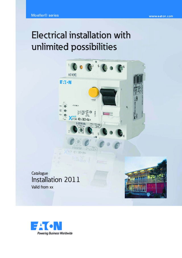
Catalogue Installation 2011 Valid from xx Electrical installation with unlimited possibilities Moeller® series www.eaton.com
1 Table of Contents Protective Devices / Components Protective Devices Miniature Circuit Breakers (MCBs) Page 2 Residual Current Devices (RCDs) Page 33 Residual Current Devices Digital (RCDs) Page 44 Add-on Residual Current Protection Unit Page 48 Main Protective Device Page 55 Leakage Current Monitor Page 57 Combined RCD/MCB Devices Page 59 Electronic Combined RCD/MCB Devices Page 70 Accessories for Protective Devices Page 79 Auxiliary Switch, RCD-Tripping Module, Shunt Trip Release, Undervoltage Release, Remote Control and Automatic Switching Device Surge Protection Page 82 Controlling & Switching Page 92 Main Load Disconnector Switch, Installation Contactor, Relay, Signalling Devices, Transformer Busbar Systems Page 110 Plug-in Busbar System, Busbar block (fork and pin)SASY Busbar System Fuse Devices (Protective Devices) Page 128 Measuring Devices Page 161 Other Accessories Page 165 Technical Data Page 177
2 • High-quality miniature circuit breakers for residential applications• Contact position indicator red - green• Comprehensive range of accessories suitable for subsequent instal- lation • Rated currents up to 63 A• Tripping characteristics B, C• Rated breaking capacity 4.5 kA according to IEC/EN 60898-1 Miniature Circuit Breakers CLS4DE Protective Devices SG83711
3 Miniature Circuit Breakers CLS4 DE Characteristic B Rated Current I n (A) Type Designation Article No. Units per package 1-pole 246101316202532405063 CLS4-B2 247824 12 / 120 CLS4-B4 247825 12 / 120 CLS4-B6 247826 12 / 120 CLS4-B10 247827 12 / 120 CLS4-B13 247828 12 / 120 CLS4-B16 247829 12 / 120 CLS4-B20 247830 12 / 120 CLS4-B25 247831 12 / 120 CLS4-B32 247832 12 / 120 CLS4-B40 247833 12 / 120 CLS4-B50 247834 12 / 120 CLS4-B63 247835 12 / 120 1+N-pole246101316202532405063 CLS4-B2/1N 247848 1 / 60 CLS4-B4/1N 247849 1 / 60 CLS4-B6/1N 247850 1 / 60 CLS4-B10/1N 247851 1 / 60 CLS4-B13/1N 247852 1 / 60 CLS4-B16/1N 247853 1 / 60 CLS4-B20/1N 247854 1 / 60 CLS4-B25/1N 247855 1 / 60 CLS4-B32/1N 247856 1 / 60 CLS4-B40/1N 247857 1 / 60 CLS4-B50/1N 247858 1 / 60 CLS4-B63/1N 247859 1 / 60 2-pole246101316202532405063 CLS4-B2/2 247872 1 / 60 CLS4-B4/2 247873 1 / 60 CLS4-B6/2 247874 1 / 60 CLS4-B10/2 247875 1 / 60 CLS4-B13/2 247876 1 / 60 CLS4-B16/2 247877 1 / 60 CLS4-B20/2 247878 1 / 60 CLS4-B25/2 247879 1 / 60 CLS4-B32/2 247880 1 / 60 CLS4-B40/2 247881 1 / 60 CLS4-B50/2 247882 1 / 60 CLS4-B63/2 247883 1 / 60 3-pole246101316202532405063 CLS4-B2/3 247896 1 / 40 CLS4-B4/3 247897 1 / 40 CLS4-B6/3 247898 1 / 40 CLS4-B10/3 247899 1 / 40 CLS4-B13/3 247900 1 / 40 CLS4-B16/3 247901 1 / 40 CLS4-B20/3 247902 1 / 40 CLS4-B25/3 247903 1 / 40 CLS4-B32/3 247904 1 / 40 CLS4-B40/3 247905 1 / 40 CLS4-B50/3 247906 1 / 40 CLS4-B63/3 247907 1 / 40 3+N-pole CLS4-B2/3N 247920 1 / 30 CLS4-B4/3N 247921 1 / 30 CLS4-B6/3N 247922 1 / 30 CLS4-B10/3N 247923 1 / 30 CLS4-B13/3N 247924 1 / 30 CLS4-B16/3N 247925 1 / 30 CLS4-B20/3N 247926 1 / 30 CLS4-B25/3N 247927 1 / 30 CLS4-B32/3N 247928 1 / 30 CLS4-B40/3N 247929 1 / 30 CLS4-B50/3N 247930 1 / 30 CLS4-B63/3N 247931 1 / 30 246101316202532405063 Protective Devices SG83011 SG82811 SG82711 SG83611 SG83811
4 Protective Devices Rated Current I n (A) Type Designation Article No. Units per package 4-pole 246101316202532405063 CLS4-B2/4 247944 1 / 30 CLS4-B4/4 247945 1 / 30 CLS4-B6/4 247946 1 / 30 CLS4-B10/4 247947 1 / 30 CLS4-B13/4 247948 1 / 30 CLS4-B16/4 247949 1 / 30 CLS4-B20/4 247950 1 / 30 CLS4-B25/4 247951 1 / 30 CLS4-B32/4 247952 1 / 30 CLS4-B40/4 247953 1 / 30 CLS4-B50/4 247955 1 / 30 CLS4-B63/4 247956 1 / 30 SG83711
5 Miniature Circuit Breakers CLS4 DE Characteristic C Rated Current I n (A) Type Designation Article No. Units per package 1-pole 246101316202532405063 CLS4-C2 247836 12 / 120 CLS4-C4 247837 12 / 120 CLS4-C6 247838 12 / 120 CLS4-C10 247839 12 / 120 CLS4-C13 247840 12 / 120 CLS4-C16 247841 12 / 120 CLS4-C20 247842 12 / 120 CLS4-C25 247843 12 / 120 CLS4-C32 247844 12 / 120 CLS4-C40 247845 12 / 120 CLS4-C50 247846 12 / 120 CLS4-C63 247847 12 / 120 1+N-pole246101316202532405063 CLS4-C2/1N 247860 1 / 60 CLS4-C4/1N 247861 1 / 60 CLS4-C6/1N 247862 1 / 60 CLS4-C10/1N 247863 1 / 60 CLS4-C13/1N 247864 1 / 60 CLS4-C16/1N 247865 1 / 60 CLS4-C20/1N 247866 1 / 60 CLS4-C25/1N 247867 1 / 60 CLS4-C32/1N 247868 1 / 60 CLS4-C40/1N 247869 1 / 60 CLS4-C50/1N 247870 1 / 60 CLS4-C63/1N 247871 1 / 60 2-pole246101316202532405063 CLS4-C2/2 247884 1 / 60 CLS4-C4/2 247885 1 / 60 CLS4-C6/2 247886 1 / 60 CLS4-C10/2 247887 1 / 60 CLS4-C13/2 247888 1 / 60 CLS4-C16/2 247889 1 / 60 CLS4-C20/2 247890 1 / 60 CLS4-C25/2 247891 1 / 60 CLS4-C32/2 247892 1 / 60 CLS4-C40/2 247893 1 / 60 CLS4-C50/2 247894 1 / 60 CLS4-C63/2 247895 1 / 60 3-pole246101316202532405063 CLS4-C2/3 247908 1 / 40 CLS4-C4/3 247909 1 / 40 CLS4-C6/3 247910 1 / 40 CLS4-C10/3 247911 1 / 40 CLS4-C13/3 247912 1 / 40 CLS4-C16/3 247913 1 / 40 CLS4-C20/3 247914 1 / 40 CLS4-C25/3 247915 1 / 40 CLS4-C32/3 247916 1 / 40 CLS4-C40/3 247917 1 / 40 CLS4-C50/3 247918 1 / 40 CLS4-C63/3 247919 1 / 40 3+N-pole CLS4-C2/3N 247932 1 / 30 CLS4-C4/3N 247933 1 / 30 CLS4-C6/3N 247934 1 / 30 CLS4-C10/3N 247935 1 / 30 CLS4-C13/3N 247936 1 / 30 CLS4-C16/3N 247937 1 / 30 CLS4-C20/3N 247938 1 / 30 CLS4-C25/3N 247939 1 / 30 CLS4-C32/3N 247940 1 / 30 CLS4-C40/3N 247941 1 / 30 CLS4-C50/3N 247942 1 / 30 CLS4-C63/3N 247943 1 / 30 246101316202532405063 Protective Devices SG83011 SG82811 SG82711 SG83611 SG83811
6 Protective Devices Rated Current I n (A) Type Designation Article No. Units per package 4-pole 246101316202532405063 CLS4-C2/4 247957 1 / 30 CLS4-C4/4 247958 1 / 30 CLS4-C6/4 247959 1 / 30 CLS4-C10/4 247960 1 / 30 CLS4-C13/4 247961 1 / 30 CLS4-C16/4 247962 1 / 30 CLS4-C20/4 247963 1 / 30 CLS4-C25/4 247964 1 / 30 CLS4-C32/4 247965 1 / 30 CLS4-C40/4 247966 1 / 30 CLS4-C50/4 247967 1 / 30 CLS4-C63/4 247968 1 / 30 SG83711
7 • High-quality miniature circuit breakers for commercial and residen- tial applications • Contact position indicator red - green• Comprehensive range of accessories suitable for subsequent instal- lation • Rated currents up to 63 A• Tripping characteristics B, C, D• Rated breaking capacity 6 kA according to IEC/EN 60898-1 Miniature Circuit Breakers CLS6DE Protective Devices SG10411
8 Miniature Circuit Breakers CLS6 DE Characteristic B Rated Current I n (A) Type Designation Article No. Units per package 1-pole 246101316202532405063 CLS6-B2 247596 12 / 120 CLS6-B4 247597 12 / 120 CLS6-B6 247598 12 / 120 CLS6-B10 247599 12 / 120 CLS6-B13 247600 12 / 120 CLS6-B16 247601 12 / 120 CLS6-B20 247602 12 / 120 CLS6-B25 247603 12 / 120 CLS6-B32 247604 12 / 120 CLS6-B40 247605 12 / 120 CLS6-B50 247606 12 / 120 CLS6-B63 247607 12 / 120 1+N-pole246101316202532405063 CLS6-B2/1N 247630 1 / 60 CLS6-B4/1N 247631 1 / 60 CLS6-B6/1N 247632 1 / 60 CLS6-B10/1N 247633 1 / 60 CLS6-B13/1N 247634 1 / 60 CLS6-B16/1N 247635 1 / 60 CLS6-B20/1N 247636 1 / 60 CLS6-B25/1N 247637 1 / 60 CLS6-B32/1N 247638 1 / 60 CLS6-B40/1N 247639 1 / 60 CLS6-B50/1N 247640 1 / 60 CLS6-B63/1N 247641 1 / 60 2-pole246101316202532405063 CLS6-B2/2 247664 1 / 60 CLS6-B4/2 247665 1 / 60 CLS6-B6/2 247666 1 / 60 CLS6-B10/2 247667 1 / 60 CLS6-B13/2 247668 1 / 60 CLS6-B16/2 247669 1 / 60 CLS6-B20/2 247670 1 / 60 CLS6-B25/2 247671 1 / 60 CLS6-B32/2 247672 1 / 60 CLS6-B40/2 247673 1 / 60 CLS6-B50/2 247674 1 / 60 CLS6-B63/2 247675 1 / 60 3-pole246101316202532405063 CLS6-B2/3 247698 1 / 40 CLS6-B4/3 247699 1 / 40 CLS6-B6/3 247700 1 / 40 CLS6-B10/3 247701 1 / 40 CLS6-B13/3 247702 1 / 40 CLS6-B16/3 247703 1 / 40 CLS6-B20/3 247704 1 / 40 CLS6-B25/3 247705 1 / 40 CLS6-B32/3 247706 1 / 40 CLS6-B40/3 247707 1 / 40 CLS6-B50/3 247708 1 / 40 CLS6-B63/3 247709 1 / 40 3+N-pole246101316202532405063 CLS6-B2/3N 247732 1 / 30 CLS6-B4/3N 247733 1 / 30 CLS6-B6/3N 247734 1 / 30 CLS6-B10/3N 247735 1 / 30 CLS6-B13/3N 247736 1 / 30 CLS6-B16/3N 247737 1 / 30 CLS6-B20/3N 247738 1 / 30 CLS6-B25/3N 247739 1 / 30 CLS6-B32/3N 247740 1 / 30 CLS6-B40/3N 247741 1 / 30 CLS6-B50/3N 247742 1 / 30 CLS6-B63/3N 247743 1 / 30 Protective Devices SG10011 SG10111 SG10211 SG10311 SG10511
9 Protective Devices Rated Current I n (A) Type Designation Article No. Units per package 4-pole 246101316202532405063 CLS6-B2/4 247766 1 / 30 CLS6-B4/4 247767 1 / 30 CLS6-B6/4 247768 1 / 30 CLS6-B10/4 247769 1 / 30 CLS6-B13/4 247770 1 / 30 CLS6-B16/4 247771 1 / 30 CLS6-B20/4 247772 1 / 30 CLS6-B25/4 247773 1 / 30 CLS6-B32/4 247774 1 / 30 CLS6-B40/4 247775 1 / 30 CLS6-B50/4 247776 1 / 30 CLS6-B63/4 247777 1 / 30 Miniature Circuit Breakers CLS6 DE Characteristic C Rated Current I n (A) Type Designation Article No. Units per package 1-pole 246101316202532405063 CLS6-C2 247608 12 / 120 CLS6-C4 247609 12 / 120 CLS6-C6 247610 12 / 120 CLS6-C10 247611 12 / 120 CLS6-C13 247612 12 / 120 CLS6-C16 247613 12 / 120 CLS6-C20 247614 12 / 120 CLS6-C25 247615 12 / 120 CLS6-C32 247616 12 / 120 CLS6-C40 247617 12 / 120 CLS6-C50 247618 12 / 120 CLS6-C63 247619 12 / 120 1+N-pole246101316202532405063 CLS6-C2/1N 247642 1 / 60 CLS6-C4/1N 247643 1 / 60 CLS6-C6/1N 247644 1 / 60 CLS6-C10/1N 247645 1 / 60 CLS6-C13/1N 247646 1 / 60 CLS6-C16/1N 247647 1 / 60 CLS6-C20/1N 247648 1 / 60 CLS6-C25/1N 247649 1 / 60 CLS6-C32/1N 247650 1 / 60 CLS6-C40/1N 247651 1 / 60 CLS6-C50/1N 247652 1 / 60 CLS6-C63/1N 247653 1 / 60 2-pole 246101316202532405063 CLS6-C2/2 247676 1 / 60 CLS6-C4/2 247677 1 / 60 CLS6-C6/2 247678 1 / 60 CLS6-C10/2 247679 1 / 60 CLS6-C13/2 247680 1 / 60 CLS6-C16/2 247681 1 / 60 CLS6-C20/2 247682 1 / 60 CLS6-C25/2 247683 1 / 60 CLS6-C32/2 247684 1 / 60 CLS6-C40/2 247685 1 / 60 CLS6-C50/2 247686 1 / 60 CLS6-C63/2 247687 1 / 60 SG10411 SG10011 SG10111 SG10211
10 Rated Current I n (A) Type Designation Article No. Units per package 3-pole 246101316202532405063 CLS6-C2/3 247710 1 / 40 CLS6-C4/3 247711 1 / 40 CLS6-C6/3 247712 1 / 40 CLS6-C10/3 247713 1 / 40 CLS6-C13/3 247714 1 / 40 CLS6-C16/3 247715 1 / 40 CLS6-C20/3 247716 1 / 40 CLS6-C25/3 247717 1 / 40 CLS6-C32/3 247718 1 / 40 CLS6-C40/3 247719 1 / 40 CLS6-C50/3 247720 1 / 40 CLS6-C63/3 247721 1 / 40 3+N-pole246101316202532405063 CLS6-C2/3N 247744 1 / 30 CLS6-C4/3N 247745 1 / 30 CLS6-C6/3N 247746 1 / 30 CLS6-C10/3N 247747 1 / 30 CLS6-C13/3N 247748 1 / 30 CLS6-C16/3N 247749 1 / 30 CLS6-C20/3N 247750 1 / 30 CLS6-C25/3N 247751 1 / 30 CLS6-C32/3N 247752 1 / 30 CLS6-C40/3N 247753 1 / 30 CLS6-C50/3N 247754 1 / 30 CLS6-C63/3N 247755 1 / 30 4-pole246101316202532405063 CLS6-C2/4 247778 1 / 30 CLS6-C4/4 247779 1 / 30 CLS6-C6/4 247780 1 / 30 CLS6-C10/4 247781 1 / 30 CLS6-C13/4 247782 1 / 30 CLS6-C16/4 247783 1 / 30 CLS6-C20/4 247784 1 / 30 CLS6-C25/4 247785 1 / 30 CLS6-C32/4 247786 1 / 30 CLS6-C40/4 247787 1 / 30 CLS6-C50/4 247788 1 / 30 CLS6-C63/4 247789 1 / 30 Miniature Circuit Breakers CLS6 DE Characteristic D Rated Current I n (A) Type Designation Article No. Units per package 1-pole 24610131620253240 CLS6-D2 247620 12 / 120 CLS6-D4 247621 12 / 120 CLS6-D6 247622 12 / 120 CLS6-D10 247623 12 / 120 CLS6-D13 247624 12 / 120 CLS6-D16 247625 12 / 120 CLS6-D20 247626 12 / 120 CLS6-D25 247627 12 / 120 CLS6-D32 247628 12 / 120 CLS6-D40 247629 12 / 120 1+N-pole24610131620253240 CLS6-D2/1N 247654 1 / 60 CLS6-D4/1N 247655 1 / 60 CLS6-D6/1N 247656 1 / 60 CLS6-D10/1N 247657 1 / 60 CLS6-D13/1N 247658 1 / 60 CLS6-D16/1N 247659 1 / 60 CLS6-D20/1N 247660 1 / 60 CLS6-D25/1N 247661 1 / 60 CLS6-D32/1N 247662 1 / 60 CLS6-D40/1N 247663 1 / 60 Protective Devices SG10311 SG10511 SG10411 SG10011 SG10111
11 Protective Devices Rated Current I n (A) Type Designation Article No. Units per package 2-pole 3+N-pole24610131620253240 CLS6-D2/3N 247756 1 / 30 CLS6-D4/3N 247757 1 / 30 CLS6-D6/3N 247758 1 / 30 CLS6-D10/3N 247759 1 / 30 CLS6-D13/3N 247760 1 / 30 CLS6-D16/3N 247761 1 / 30 CLS6-D20/3N 247762 1 / 30 CLS6-D25/3N 247763 1 / 30 CLS6-D32/3N 247764 1 / 30 CLS6-D40/3N 247765 1 / 30 24610131620253240 CLS6-D2/2 247688 1 / 60 CLS6-D4/2 247689 1 / 60 CLS6-D6/2 247690 1 / 60 CLS6-D10/2 247691 1 / 60 CLS6-D13/2 247692 1 / 60 CLS6-D16/2 247693 1 / 60 CLS6-D20/2 247694 1 / 60 CLS6-D25/2 247695 1 / 60 CLS6-D32/2 247696 1 / 60 CLS6-D40/2 247697 1 / 60 3-pole 24610131620253240 CLS6-D2/3 247722 1 / 40 CLS6-D4/3 247723 1 / 40 CLS6-D6/3 247724 1 / 40 CLS6-D10/3 247725 1 / 40 CLS6-D13/3 247726 1 / 40 CLS6-D16/3 247727 1 / 40 CLS6-D20/3 247728 1 / 40 CLS6-D25/3 247729 1 / 40 CLS6-D32/3 247730 1 / 40 CLS6-D40/3 247731 1 / 40 4-pole24610131620253240 CLS6-D2/4 247790 1 / 30 CLS6-D4/4 247791 1 / 30 CLS6-D6/4 247792 1 / 30 CLS6-D10/4 247793 1 / 30 CLS6-D13/4 247794 1 / 30 CLS6-D16/4 247795 1 / 30 CLS6-D20/4 247796 1 / 30 CLS6-D25/4 247797 1 / 30 CLS6-D32/4 247798 1 / 30 CLS6-D40/4 247799 1 / 30 SG10511 SG10211 SG10311 SG10411
12 Protective Devices • High-quality miniature circuit breakers for DC-applications• Contact position indicator red - green• Comprehensive range of accessories suitable for subsequent installation• Rated currents up to 50 A• Tripping characteristic C• Rated breaking capacity 10 kA according to IEC/EN 660898-1• Up to 250 V DC per pole Miniature Circuit Breakers CLS6-DC SG83111
13 Miniature Circuit Breakers CLS6-DC for AC/DC DE Characteristic C Rated Current I n (A) Type Designation Article No. Units per package 1-pole 23461013162025324050 CLS6-C2-DC 247800 12 / 120 CLS6-C3-DC 247801 12 / 120 CLS6-C4-DC 247802 12 / 120 CLS6-C6-DC 247803 12 / 120 CLS6-C10-DC 247804 12 / 120 CLS6-C13-DC 247805 12 / 120 CLS6-C16-DC 247806 12 / 120 CLS6-C20-DC 247807 12 / 120 CLS6-C25-DC 247808 12 / 120 CLS6-C32-DC 247809 12 / 120 CLS6-C40-DC 247810 12 / 120 CLS6-C50-DC 247811 12 / 120 2-pole23461013162025324050 CLS6-C2/2-DC 247812 1 / 60 CLS6-C3/2-DC 247813 1 / 60 CLS6-C4/2-DC 247814 1 / 60 CLS6-C6/2-DC 247815 1 / 60 CLS6-C10/2-DC 247816 1 / 60 CLS6-C13/2-DC 247817 1 / 60 CLS6-C16/2-DC 247818 1 / 60 CLS6-C20/2-DC 247819 1 / 60 CLS6-C25/2-DC 247820 1 / 60 CLS6-C32/2-DC 247821 1 / 60 CLS6-C40/2-DC 247822 1 / 60 CLS6-C50/2-DC 247823 1 / 60 Protective Devices SG83111 SG82611
14 Protective Devices • High-quality miniature circuit breakers for commercial and residential applications • Contact position indicator red - green• Guide for secure terminal connection• 3-position DIN rail clip, permits removal from existing busbar system• Comprehensive range of accessories suitable for subsequent installa- tion • Rated currents up to 63 A• Tripping characteristics B, C, D• Rated breaking capacity 10 kA according to IEC/EN 60898-1 Miniature Circuit Breakers PL7 SG06511
15 Protective Devices Miniature Circuit Breakers PL710 kA, Characteristic B Rated Current I n (A) Type Designation Article No. Units per package 1-pole 11.51.622.533.545681012131516202532405063 PL7-B1/1 165052 12/120 PL7-B1,5/1 165048 12/120 PL7-B1,6/1 165049 12/120 PL7-B2/1 264839 12/120 PL7-B2,5/1 165053 12/120 PL7-B3/1 165055 12/120 PL7-B3,5/1 165054 12/120 PL7-B4/1 264850 12/120 PL7-B5/1 165056 12/120 PL7-B6/1 262673 12/120 PL7-B8/1 165057 12/120 PL7-B10/1 262674 12/120 PL7-B12/1 165050 12/120 PL7-B13/1 262675 12/120 PL7-B15/1 165051 12/120 PL7-B16/1 262676 12/120 PL7-B20/1 262677 12/120 PL7-B25/1 262678 12/120 PL7-B32/1 262679 12/120 PL7-B40/1 262690 12/120 PL7-B50/1 262691 12/120 PL7-B63/1 262692 12/120 1+N-pole11.51.622.533.545681012131516202532 PL7-B1/1N 165214 8/80 PL7-B1,5/1N 165212 8/80 PL7-B1,6/1N 165213 8/80 PL7-B2/1N 165218 8/80 PL7-B2,5/1N 165217 8/80 PL7-B3/1N 165220 8/80 PL7-B3,5/1N 165219 8/80 PL7-B4/1N 165221 8/80 PL7-B5/1N 165222 8/80 PL7-B6/1N 262727 8/80 PL7-B8/1N 165223 8/80 PL7-B10/1N 262728 8/80 PL7-B12/1N 165215 8/80 PL7-B13/1N 262729 8/80 PL7-B15/1N 165216 8/80 PL7-B16/1N 262740 8/80 PL7-B20/1N 262741 8/80 PL7-B25/1N 262742 8/80 PL7-B32/1N 262743 8/80 2-pole11.51.622.533.545681012131516202532405063 PL7-B1/2 165079 6/60 PL7-B1,5/2 165077 6/60 PL7-B1,6/2 165078 6/60 PL7-B2/2 165083 6/60 PL7-B2,5/2 165082 6/60 PL7-B3/2 165085 6/60 PL7-B3,5/2 165084 6/60 PL7-B4/2 165086 6/60 PL7-B5/2 165087 6/60 PL7-B6/2 262761 6/60 PL7-B8/2 165088 6/60 PL7-B10/2 262762 6/60 PL7-B12/2 165080 6/60 PL7-B13/2 262764 6/60 PL7-B15/2 165081 6/60 PL7-B16/2 262765 6/60 PL7-B20/2 262766 6/60 PL7-B25/2 262767 6/60 PL7-B32/2 262768 6/60 PL7-B40/2 262769 6/60 PL7-B50/2 263350 6/60 PL7-B63/2 263351 6/60 SG06211 SG06311 SG06411
16 Protective Devices 3-pole11.51.622.533.545681012131516202532405063 PL7-B1/3 165112 4/40 PL7-B1,5/3 165110 4/40 PL7-B1,6/3 165111 4/40 PL7-B2/3 165116 4/40 PL7-B2,5/3 165115 4/40 PL7-B3/3 165118 4/40 PL7-B3,5/3 165117 4/40 PL7-B4/3 116709 4/40 PL7-B5/3 165119 4/40 PL7-B6/3 263386 4/40 PL7-B8/3 165120 4/40 PL7-B10/3 263387 4/40 PL7-B12/3 165113 4/40 PL7-B13/3 263388 4/40 PL7-B15/3 165114 4/40 PL7-B16/3 263389 4/40 PL7-B20/3 263390 4/40 PL7-B25/3 263391 4/40 PL7-B32/3 263392 4/40 PL7-B40/3 263393 4/40 PL7-B50/3 263400 4/40 PL7-B63/3 263401 4/40 3+N-pole11.51.622.533.545681012131516202532405063 PL7-B1/3N 165251 3/30 PL7-B1,5/3N 165249 3/30 PL7-B1,6/3N 165250 3/30 PL7-B2/3N 165255 3/30 PL7-B2,5/3N 165254 3/30 PL7-B3/3N 165257 3/30 PL7-B3,5/3N 165256 3/30 PL7-B4/3N 165258 3/30 PL7-B5/3N 165259 3/30 PL7-B6/3N 263982 3/30 PL7-B8/3N 165260 3/30 PL7-B10/3N 263983 3/30 PL7-B12/3N 165252 3/30 PL7-B13/3N 263984 3/30 PL7-B15/3N 165253 3/30 PL7-B16/3N 263985 3/30 PL7-B20/3N 263986 3/30 PL7-B25/3N 263987 3/30 PL7-B32/3N 263988 3/30 PL7-B40/3N 263989 3/30 PL7-B50/3N 263990 3/30 PL7-B63/3N 263991 3/30 SG06511 SG06711 Rated Current I n (A) Type Designation Article No. Units per package 4-pole11.51.622.533.545681012131516202532405063 PL7-B1/4 165146 3/30 PL7-B1,5/4 165144 3/30 PL7-B1,6/4 165145 3/30 PL7-B2/4 165153 3/30 PL7-B2,5/4 165152 3/30 PL7-B3/4 165157 3/30 PL7-B3,5/4 165156 3/30 PL7-B4/4 165159 3/30 PL7-B5/4 165161 3/30 PL7-B6/4 165163 3/30 PL7-B8/4 165165 3/30 PL7-B10/4 165147 3/30 PL7-B12/4 165148 3/30 PL7-B13/4 165149 3/30 PL7-B15/4 165150 3/30 PL7-B16/4 165151 3/30 PL7-B20/4 165154 3/30 PL7-B25/4 165155 3/30 PL7-B32/4 165158 3/30 PL7-B40/4 165160 3/30 PL7-B50/4 165162 3/30 PL7-B63/4 165164 3/30 SG06611
17 Protective Devices Miniature Circuit Breakers PL710 kA, Characteristic C Rated Current I n (A) Type Designation Article No. Units per package 1-pole 0.160.250.50.7511.51.622.533.545681012131516202532405063 PL7-C0,16/1 262693 12/120 PL7-C0,25/1 262694 12/120 PL7-C0,5/1 262695 12/120 PL7-C0,75/1 262696 12/120 PL7-C1/1 262697 12/120 PL7-C1,5/1 165058 12/120 PL7-C1,6/1 262698 12/120 PL7-C2/1 262699 12/120 PL7-C2,5/1 165061 12/120 PL7-C3/1 165063 12/120 PL7-C3,5/1 165062 12/120 PL7-C4/1 262700 12/120 PL7-C5/1 165064 12/120 PL7-C6/1 262701 12/120 PL7-C8/1 165065 12/120 PL7-C10/1 262702 12/120 PL7-C12/1 165059 12/120 PL7-C13/1 262703 12/120 PL7-C15/1 165060 12/120 PL7-C16/1 262704 12/120 PL7-C20/1 262705 12/120 PL7-C25/1 262706 12/120 PL7-C32/1 262707 12/120 PL7-C40/1 262708 12/120 PL7-C50/1 262709 12/120 PL7-C63/1 262710 12/120 1+N-pole0.160.250.50.7511,51.622.533.545681012131516202532 PL7-C0,16/1N 165224 8/80 PL7-C0,25/1N 165225 8/80 PL7-C0,5/1N 165226 8/80 PL7-C0,75/1N 165227 8/80 PL7-C1/1N 165230 8/80 PL7-C1,5/1N 165228 8/80 PL7-C1,6/1N 165229 8/80 PL7-C2/1N 262744 8/80 PL7-C2,5/1N 165233 8/80 PL7-C3/1N 165235 8/80 PL7-C3,5/1N 165234 8/80 PL7-C4/1N 262745 8/80 PL7-C5/1N 165236 8/80 PL7-C6/1N 262746 8/80 PL7-C8/1N 165237 8/80 PL7-C10/1N 262747 8/80 PL7-C12/1N 165231 8/80 PL7-C13/1N 262748 8/80 PL7-C15/1N 165232 8/80 PL7-C16/1N 262749 8/80 PL7-C20/1N 262750 8/80 PL7-C25/1N 262751 8/80 PL7-C32/1N 262752 8/80 SG06211 SG06311
18 Protective Devices 2-pole0.160.250.50.7511.51.622.533.545681012131516202532405063 PL7-C0,16/2 165089 6/60 PL7-C0,25/2 165090 6/60 PL7-C0,5/2 263352 6/60 PL7-C0,75/2 165091 6/60 PL7-C1/2 263353 6/60 PL7-C1,5/2 165092 6/60 PL7-C1,6/2 165093 6/60 PL7-C2/2 263354 6/60 PL7-C2,5/2 165096 6/60 PL7-C3/2 165098 6/60 PL7-C3,5/2 165097 6/60 PL7-C4/2 263355 6/60 PL7-C5/2 165099 6/60 PL7-C6/2 263356 6/60 PL7-C8/2 165100 6/60 PL7-C10/2 263357 6/60 PL7-C12/2 165094 6/60 PL7-C13/2 263358 6/60 PL7-C15/2 165095 6/60 PL7-C16/2 263359 6/60 PL7-C20/2 263360 6/60 PL7-C25/2 263361 6/60 PL7-C32/2 263362 6/60 PL7-C40/2 263363 6/60 PL7-C50/2 263364 6/60 PL7-C63/2 263365 6/60 SG06411 3-pole0.160.250.50.7511.51.622.533.545681012131516202532405063 PL7-C0,16/3 165121 4/40 PL7-C0,25/3 165122 4/40 PL7-C0,5/3 263402 4/40 PL7-C0,75/3 165123 4/40 PL7-C1/3 263403 4/40 PL7-C1,5/3 165124 4/40 PL7-C1,6/3 165125 4/40 PL7-C2/3 263404 4/40 PL7-C2,5/3 165128 4/40 PL7-C3/3 165130 4/40 PL7-C3,5/3 165129 4/40 PL7-C4/3 263405 4/40 PL7-C5/3 165131 4/40 PL7-C6/3 263406 4/40 PL7-C8/3 165132 4/40 PL7-C10/3 263407 4/40 PL7-C12/3 165126 4/40 PL7-C13/3 263408 4/40 PL7-C15/3 165127 4/40 PL7-C16/3 263409 4/40 PL7-C20/3 263410 4/40 PL7-C25/3 263411 4/40 PL7-C32/3 263412 4/40 PL7-C40/3 263413 4/40 PL7-C50/3 263414 4/40 PL7-C63/3 263415 4/40 SG06511 Rated Current I n (A) Type Designation Article No. Units per package
19 Protective Devices 3+N-pole0.160.250.50.7511.51.622.533.545681012131516202532405063 PL7-C0,16/3N 165261 3/30 PL7-C0,25/3N 165262 3/30 PL7-C0,5/3N 165263 3/30 PL7-C0,75/3N 165264 3/30 PL7-C1/3N 165267 3/30 PL7-C1,5/3N 165265 3/30 PL7-C1,6/3N 165266 3/30 PL7-C2/3N 165271 3/30 PL7-C2,5/3N 165270 3/30 PL7-C3/3N 165273 3/30 PL7-C3,5/3N 165272 3/30 PL7-C4/3N 165274 3/30 PL7-C5/3N 165275 3/30 PL7-C6/3N 263992 3/30 PL7-C8/3N 165276 3/30 PL7-C10/3N 263993 3/30 PL7-C12/3N 165268 3/30 PL7-C13/3N 263994 3/30 PL7-C15/3N 165269 3/30 PL7-C16/3N 263995 3/30 PL7-C20/3N 263996 3/30 PL7-C25/3N 263997 3/30 PL7-C32/3N 263998 3/30 PL7-C40/3N 263999 3/30 PL7-C50/3N 264000 3/30 PL7-C63/3N 264001 3/30 SG06711 Rated Current I n (A) Type Designation Article No. Units per package 4-pole 0.160.250.50.7511.51.622.533.545681012131516202532405063 PL7-C0,16/4 165166 3/30 PL7-C0,25/4 165167 3/30 PL7-C0,5/4 165168 3/30 PL7-C0,75/4 165169 3/30 PL7-C1/4 165172 3/30 PL7-C1,5/4 165170 3/30 PL7-C1,6/4 165171 3/30 PL7-C2/4 165178 3/30 PL7-C2,5/4 165177 3/30 PL7-C3/4 165182 3/30 PL7-C3,5/4 165181 3/30 PL7-C4/4 165184 3/30 PL7-C5/4 165186 3/30 PL7-C6/4 165188 3/30 PL7-C8/4 165190 3/30 PL7-C10/4 165173 3/30 PL7-C12/4 165174 3/30 PL7-C13/4 165175 3/30 PL7-C15/4 165176 3/30 PL7-C16/4 107329 3/30 PL7-C20/4 165179 3/30 PL7-C25/4 165180 3/30 PL7-C32/4 165183 3/30 PL7-C40/4 165185 3/30 PL7-C50/4 165187 3/30 PL7-C63/4 165189 3/30 SG06611
20 Protective Devices Miniature Circuit Breakers PL710 kA, Characteristic D Rated Current I n (A) Type Designation Article No. Units per package 1-pole 0.511.51.622.533.54568101213151620253240 PL7-D0,5/1 165066 12/120 PL7-D1/1 165071 12/120 PL7-D1,5/1 165067 12/120 PL7-D1,6/1 165068 12/120 PL7-D2/1 262711 12/120 PL7-D2,5/1 165072 12/120 PL7-D3/1 165074 12/120 PL7-D3,5/1 165073 12/120 PL7-D4/1 262712 12/120 PL7-D5/1 165075 12/120 PL7-D6/1 262713 12/120 PL7-D8/1 165076 12/120 PL7-D10/1 262714 12/120 PL7-D12/1 165069 12/120 PL7-D13/1 262715 12/120 PL7-D15/1 165070 12/120 PL7-D16/1 262716 12/120 PL7-D20/1 262717 12/120 PL7-D25/1 262718 12/120 PL7-D32/1 262719 12/120 PL7-D40/1 262720 12/120 2-pole0.511.51.622.533.54568101213151620253240 PL7-D0,5/2 165101 6/60 PL7-D1/2 108184 6/60 PL7-D1,5/2 165102 6/60 PL7-D1,6/2 165103 6/60 PL7-D2/2 263366 6/60 PL7-D2,5/2 165106 6/60 PL7-D3/2 108185 6/60 PL7-D3,5/2 165107 6/60 PL7-D4/2 263367 6/60 PL7-D5/2 165108 6/60 PL7-D6/2 263368 6/60 PL7-D8/2 165109 6/60 PL7-D10/2 263369 6/60 PL7-D12/2 165104 6/60 PL7-D13/2 263380 6/60 PL7-D15/2 165105 6/60 PL7-D16/2 263381 6/60 PL7-D20/2 263382 6/60 PL7-D25/2 263383 6/60 PL7-D32/2 263384 6/60 PL7-D40/2 263385 6/60 SG06211 SG06411 1+N-pole0.511.51.622.533.5456810121315162025 PL7-D0,5/1N 165238 8/80 PL7-D1/1N 165241 8/80 PL7-D1,5/1N 165239 8/80 PL7-D1,6/1N 165240 8/80 PL7-D2/1N 262753 8/80 PL7-D2,5/1N 165244 8/80 PL7-D3/1N 165246 8/80 PL7-D3,5/1N 165245 8/80 PL7-D4/1N 262754 8/80 PL7-D5/1N 165247 8/80 PL7-D6/1N 262755 8/80 PL7-D8/1N 165248 8/80 PL7-D10/1N 262756 8/80 PL7-D12/1N 165242 8/80 PL7-D13/1N 262757 8/80 PL7-D15/1N 165243 8/80 PL7-D16/1N 262758 8/80 PL7-D20/1N 262759 8/80 PL7-D25/1N 262760 8/80 SG06311
Rated Current I n (A) Type Designation Article No. Units per package 3+N-pole0.511.51.622.533.54568101213151620253240 PL7-D0,5/3N 165277 3/30 PL7-D1/3N 165280 3/30 PL7-D1,5/3N 165278 3/30 PL7-D1,6/3N 165279 3/30 PL7-D2/3N 165284 3/30 PL7-D2,5/3N 165283 3/30 PL7-D3/3N 165286 3/30 PL7-D3,5/3N 165285 3/30 PL7-D4/3N 165287 3/30 PL7-D5/3N 165288 3/30 PL7-D6/3N 264002 3/30 PL7-D8/3N 165289 3/30 PL7-D10/3N 264003 3/30 PL7-D12/3N 165281 3/30 PL7-D13/3N 264004 3/30 PL7-D15/3N 165282 3/30 PL7-D16/3N 264005 3/30 PL7-D20/3N 264006 3/30 PL7-D25/3N 264007 3/30 PL7-D32/3N 264008 3/30 PL7-D40/3N 264009 3/30 SG06711 3-pole 0.511.51.622.533.54568101213151620253240 PL7-D0,5/3 165133 4/40 PL7-D1/3 165136 4/40 PL7-D1,5/3 165134 4/40 PL7-D1,6/3 165135 4/40 PL7-D2/3 263416 4/40 PL7-D2,5/3 165139 4/40 PL7-D3/3 165141 4/40 PL7-D3,5/3 165140 4/40 PL7-D4/3 263417 4/40 PL7-D5/3 165142 4/40 PL7-D6/3 263418 4/40 PL7-D8/3 165143 4/40 PL7-D10/3 263419 4/40 PL7-D12/3 165137 4/40 PL7-D13/3 263420 4/40 PL7-D15/3 165138 4/40 PL7-D16/3 263421 4/40 PL7-D20/3 263422 4/40 PL7-D25/3 263423 4/40 PL7-D32/3 263424 4/40 PL7-D40/3 263425 4/40 SG06511 4-pole0.511.51.622.533.54568101213151620253240 PL7-D0,5/4 165191 3/30 PL7-D1/4 165194 3/30 PL7-D1,5/4 165192 3/30 PL7-D1,6/4 165193 3/30 PL7-D2/4 165201 3/30 PL7-D2,5/4 165200 3/30 PL7-D3/4 165205 3/30 PL7-D3,5/4 165204 3/30 PL7-D4/4 165207 3/30 PL7-D5/4 165209 3/30 PL7-D6/4 165210 3/30 PL7-D8/4 165211 3/30 PL7-D10/4 165195 3/30 PL7-D12/4 165196 3/30 PL7-D13/4 165197 3/30 PL7-D15/4 165198 3/30 PL7-D16/4 165199 3/30 PL7-D20/4 165202 3/30 PL7-D25/4 165203 3/30 PL7-D32/4 165206 3/30 PL7-D40/4 165208 3/30 SG06611 21 Protective Devices
22 Protective Devices • High-quality miniature circuit breakers for DC-applications• Contact position indicator red - green• Guide for secure terminal connection• 3-position DIN rail clip, permits removal from existing busbar system• Comprehensive range of accessories suitable for subsequent installation• Rated currents up to 50 A• Tripping characteristic C• Rated breaking capacity 10 kA according to IEC/EN 60947-2• Up to 250 V DC per pole Miniature Circuit Breakers PL7-DC SG06211
23 Protective Devices Miniature Circuit Breakers PL7-DC for AC/DC10 kA, Characteristic C Rated Current I n (A) Type Designation Article No. Units per package 1-pole 123461013162025324050 PL7-C1/1-DC 264851 12/120 PL7-C2/1-DC 264883 12/120 PL7-C3/1-DC 264884 12/120 PL7-C4/1-DC 264885 12/120 PL7-C6/1-DC 264886 12/120 PL7-C10/1-DC 264887 12/120 PL7-C13/1-DC 264888 12/120 PL7-C16/1-DC 264889 12/120 PL7-C20/1-DC 264890 12/120 PL7-C25/1-DC 264891 12/120 PL7-C32/1-DC 264892 12/120 PL7-C40/1-DC 264893 12/120 PL7-C50/1-DC 264894 12/120 2-pole123461013162025324050 PL7-C1/2-DC 264895 6/60 PL7-C2/2-DC 264896 6/60 PL7-C3/2-DC 264897 6/60 PL7-C4/2-DC 264898 6/60 PL7-C6/2-DC 264899 6/60 PL7-C10/2-DC 264900 6/60 PL7-C13/2-DC 264901 6/60 PL7-C16/2-DC 264902 6/60 PL7-C20/2-DC 264903 6/60 PL7-C25/2-DC 264904 6/60 PL7-C32/2-DC 264905 6/60 PL7-C40/2-DC 264906 6/60 PL7-C50/2-DC 264907 6/60 SG06211 SG06411
24 • Contact position indicator red - green• Two plug-in terminals at the output side• Single-wire lines can be connected without tools• Plug-in terminals can be opened conveniently by means of a screw- driver • Guide for secure terminal connection below• 3-position DIN rail clip, permits removal from existing busbar sys- tem • Comprehensive range of accessories suitable for subsequent instal- lation • Rated currents up to 16 A• Tripping characteristics B, C, D• Rated breaking capacity 10 kA according to IEC/EN 60898-1 Miniature Circuit Breakers with Plug-in Terminals PLI Protective Devices SG33911
25 Protective Devices Miniature Circuit Breakers with Plug-in Terminals at the output side PLI10 kA, Characteristic B Rated current I n (A) Type Designation Article No. Units per package 1-pole 2468101316 PLI-B2/1 101245 12 / 120 PLI-B4/1 101246 12 / 120 PLI-B6/1 101247 12 / 120 PLI-B8/1 101248 12 / 120 PLI-B10/1 101249 12 / 120 PLI-B13/1 101250 12 / 120 PLI-B16/1 101251 12 / 120 1+N-pole, 2 Module Units (MU)2468101316 PLI-B2/1N 101266 1 / 60 PLI-B4/1N 101267 1 / 60 PLI-B6/1N 101268 1 / 60 PLI-B8/1N 101269 1 / 60 PLI-B10/1N 101270 1 / 60 PLI-B13/1N 101271 1 / 60 PLI-B16/1N 101272 1 / 60 2-pole2468101316 PLI-B2/2 101287 1 / 60 PLI-B4/2 101288 1 / 60 PLI-B6/2 101289 1 / 60 PLI-B8/2 101290 1 / 60 PLI-B10/2 101291 1 / 60 PLI-B13/2 101292 1 / 60 PLI-B16/2 101293 1 / 60 3-pole2468101316 PLI-B2/3 101308 1 / 40 PLI-B4/3 101309 1 / 40 PLI-B6/3 101310 1 / 40 PLI-B8/3 101311 1 / 40 PLI-B10/3 101312 1 / 40 PLI-B13/3 101313 1 / 40 PLI-B16/3 101314 1 / 40 3+N-pole2468101316 PLI-B2/3N 101329 1 / 30 PLI-B4/3N 101330 1 / 30 PLI-B6/3N 101331 1 / 30 PLI-B8/3N 101332 1 / 30 PLI-B10/3N 101333 1 / 30 PLI-B13/3N 101334 1 / 30 PLI-B16/3N 101335 1 / 30 4-pole2468101316 PLI-B2/4 101350 1 / 30 PLI-B4/4 101351 1 / 30 PLI-B6/4 101352 1 / 30 PLI-B8/4 101353 1 / 30 PLI-B10/4 101354 1 / 30 PLI-B13/4 101355 1 / 30 PLI-B16/4 101356 1 / 30 SG11511 SG20011 SG19511 SG33911 SG19211 SG39011
26 Protective Devices Miniature Circuit Breakers with Plug-in Terminals at the output side PLI10 kA, Characteristic C Rated current I n (A) Type Designation Article No. Units per package 1-pole 2468101316 PLI-C2/1 101252 12 / 120 PLI-C4/1 101253 12 / 120 PLI-C6/1 101254 12 / 120 PLI-C8/1 101255 12 / 120 PLI-C10/1 101256 12 / 120 PLI-C13/1 101257 12 / 120 PLI-C16/1 101258 12 / 120 1+N-pole, 2 Module Units (MU)2468101316 PLI-C2/1N 101273 1 / 60 PLI-C4/1N 101274 1 / 60 PLI-C6/1N 101275 1 / 60 PLI-C8/1N 101276 1 / 60 PLI-C10/1N 101277 1 / 60 PLI-C13/1N 101278 1 / 60 PLI-C16/1N 101279 1 / 60 2-pole2468101316 PLI-C2/2 101294 1 / 60 PLI-C4/2 101295 1 / 60 PLI-C6/2 101296 1 / 60 PLI-C8/2 101297 1 / 60 PLI-C10/2 101298 1 / 60 PLI-C13/2 101299 1 / 60 PLI-C16/2 101300 1 / 60 3-pole2468101316 PLI-C2/3 101315 1 / 40 PLI-C4/3 101316 1 / 40 PLI-C6/3 101317 1 / 40 PLI-C8/3 101318 1 / 40 PLI-C10/3 101319 1 / 40 PLI-C13/3 101320 1 / 40 PLI-C16/3 101321 1 / 40 3+N-pole2468101316 PLI-C2/3N 101336 1 / 30 PLI-C4/3N 101337 1 / 30 PLI-C6/3N 101338 1 / 30 PLI-C8/3N 101339 1 / 30 PLI-C10/3N 101340 1 / 30 PLI-C13/3N 101341 1 / 30 PLI-C16/3N 101342 1 / 30 4-pole2468101316 PLI-C2/4 101357 1 / 30 PLI-C4/4 101358 1 / 30 PLI-C6/4 101359 1 / 30 PLI-C8/4 101360 1 / 30 PLI-C10/4 101361 1 / 30 PLI-C13/4 101362 1 / 30 PLI-C16/4 101363 1 / 30 SG11511 SG19511 SG33911 SG20011 SG19211 SG39011
27 Protective Devices Miniature Circuit Breakers with Plug-in Terminals at the output side PLI10 kA, Characteristic D Rated current I n (A) Type Designation Article No. Units per package 1-pole 2468101316 PLI-D2/1 101259 12 / 120 PLI-D4/1 101260 12 / 120 PLI-D6/1 101261 12 / 120 PLI-D8/1 101262 12 / 120 PLI-D10/1 101263 12 / 120 PLI-D13/1 101264 12 / 120 PLI-D16/1 101265 12 / 120 1+N-pole, 2 Module Units (MU)2468101316 PLI-D2/1N 101280 1 / 60 PLI-D4/1N 101281 1 / 60 PLI-D6/1N 101282 1 / 60 PLI-D8/1N 101283 1 / 60 PLI-D10/1N 101284 1 / 60 PLI-D13/1N 101285 1 / 60 PLI-D16/1N 101286 1 / 60 2-pole2468101316 PLI-D2/2 101301 1 / 60 PLI-D4/2 101302 1 / 60 PLI-D6/2 101303 1 / 60 PLI-D8/2 101304 1 / 60 PLI-D10/2 101305 1 / 60 PLI-D13/2 101306 1 / 60 PLI-D16/2 101307 1 / 60 3-pole2468101316 PLI-D2/3 101322 1 / 40 PLI-D4/3 101323 1 / 40 PLI-D6/3 101324 1 / 40 PLI-D8/3 101325 1 / 40 PLI-D10/3 101326 1 / 40 PLI-D13/3 101327 1 / 40 PLI-D16/3 101328 1 / 40 3+N-pole2468101316 PLI-D2/3N 101343 1 / 30 PLI-D4/3N 101344 1 / 30 PLI-D6/3N 101345 1 / 30 PLI-D8/3N 101346 1 / 30 PLI-D10/3N 101347 1 / 30 PLI-D13/3N 101348 1 / 30 PLI-D16/3N 101349 1 / 30 4-pole2468101316 PLI-D2/4 101364 1 / 30 PLI-D4/4 101365 1 / 30 PLI-D6/4 101366 1 / 30 PLI-D8/4 101367 1 / 30 PLI-D10/4 101368 1 / 30 PLI-D13/4 101369 1 / 30 PLI-D16/4 101370 1 / 30 SG11511 SG19511 SG33911 SG20011 SG19211 SG39011
28 • High-quality miniature circuit breakers for commercial and industrial applications • Contact position indicator red - green• Accessories suitable for subsequent installation• Rated currents up to 125 A• Tripping characteristics B, C, D• Rated breaking capacity up to 25 kA according to EN 60947-2 Miniature Circuit Breakers PLHT SG43611 Protective Devices
29 Protective Devices Miniature Circuit Breakers PLHTCharacteristic B Rated Current I n (A) Type Designation Article No. Units per package 1-pole 20253240506380100125 PLHT-B20 247972 12 PLHT-B25 247973 12 PLHT-B32 247974 12 PLHT-B40 247975 12 PLHT-B50 247976 12 PLHT-B63 247977 12 PLHT-B80 247978 12 PLHT-B100 247979 12 PLHT-B125 247980 12 SG41311 2-pole20253240506380100125 PLHT-B20/2 247998 6 PLHT-B25/2 247999 6 PLHT-B32/2 248000 6 PLHT-B40/2 248001 6 PLHT-B50/2 248002 6 PLHT-B63/2 248003 6 PLHT-B80/2 248004 6 PLHT-B100/2 248005 6 PLHT-B125/2 248006 6 SG42111 3-pole20253240506380100125 PLHT-B20/3 248024 4 PLHT-B25/3 248025 4 PLHT-B32/3 248026 4 PLHT-B40/3 248027 4 PLHT-B50/3 248028 4 PLHT-B63/3 248029 4 PLHT-B80/3 248030 4 PLHT-B100/3 248031 4 PLHT-B125/3 248032 4 SG42911 3+N-pole20253240506380100125 PLHT-B20/3N 248050 3 PLHT-B25/3N 248051 3 PLHT-B32/3N 248052 3 PLHT-B40/3N 248053 3 PLHT-B50/3N 248054 3 PLHT-B63/3N 248055 3 PLHT-B80/3N 248056 3 PLHT-B100/3N 248057 3 PLHT-B125/3N 248058 3 SG45111 4-pole SG44811 20253240506380100125 PLHT-B20/4 248076 3 PLHT-B25/4 248077 3 PLHT-B32/4 248078 3 PLHT-B40/4 248079 3 PLHT-B50/4 248080 3 PLHT-B63/4 248081 3 PLHT-B80/4 248082 3 PLHT-B100/4 248083 3 PLHT-B125/4 248084 3
30 Miniature Circuit Breakers PLHTCharacteristic C Rated Current I n (A) Type Designation Article No. Units per package 1-pole 20253240506380100125 PLHT-C20 247981 12 PLHT-C25 247982 12 PLHT-C32 247983 12 PLHT-C40 247984 12 PLHT-C50 247985 12 PLHT-C63 247986 12 PLHT-C80 247987 12 PLHT-C100 247988 12 PLHT-C125 247989 12 SG41311 2-pole20253240506380100125 PLHT-C20/2 248007 6 PLHT-C25/2 248008 6 PLHT-C32/2 248009 6 PLHT-C40/2 248010 6 PLHT-C50/2 248011 6 PLHT-C63/2 248012 6 PLHT-C80/2 248013 6 PLHT-C100/2 248014 6 PLHT-C125/2 248015 6 SG42111 3-pole20253240506380100125 PLHT-C20/3 248033 4 PLHT-C25/3 248034 4 PLHT-C32/3 248035 4 PLHT-C40/3 248036 4 PLHT-C50/3 248037 4 PLHT-C63/3 248038 4 PLHT-C80/3 248039 4 PLHT-C100/3 248040 4 PLHT-C125/3 248041 4 SG42911 3+N-pole20253240506380100125 PLHT-C20/3N 248059 3 PLHT-C25/3N 248060 3 PLHT-C32/3N 248061 3 PLHT-C40/3N 248062 3 PLHT-C50/3N 248063 3 PLHT-C63/3N 248064 3 PLHT-C80/3N 248065 3 PLHT-C100/3N 248066 3 PLHT-C125/3N 248067 3 SG45111 4-pole SG44811 20253240506380100125 PLHT-C20/4 248085 3 PLHT-C25/4 248086 3 PLHT-C32/4 248087 3 PLHT-C40/4 248088 3 PLHT-C50/4 248089 3 PLHT-C63/4 248090 3 PLHT-C80/4 248091 3 PLHT-C100/4 248092 3 PLHT-C125/4 248093 3 Protective Devices
31 Protective Devices Miniature Circuit Breakers PLHTCharacteristic D Rated Current I n (A) Type Designation Article No. Units per package 1-pole 20253240506380100 PLHT-D20 247990 12 PLHT-D25 247991 12 PLHT-D32 247992 12 PLHT-D40 247993 12 PLHT-D50 247994 12 PLHT-D63 247995 12 PLHT-D80 247996 12 PLHT-D100 247997 12 SG41311 2-pole20253240506380100 PLHT-D20/2 248016 6 PLHT-D25/2 248017 6 PLHT-D32/2 248018 6 PLHT-D40/2 248019 6 PLHT-D50/2 248020 6 PLHT-D63/2 248021 6 PLHT-D80/2 248022 6 PLHT-D100/2 248023 6 SG42111 3-pole20253240506380100 PLHT-D20/3 248042 4 PLHT-D25/3 248043 4 PLHT-D32/3 248044 4 PLHT-D40/3 248045 4 PLHT-D50/3 248046 4 PLHT-D63/3 248047 4 PLHT-D80/3 248048 4 PLHT-D100/3 248049 4 SG42911 3+N-pole20253240506380100 PLHT-D20/3N 248068 3 PLHT-D25/3N 248069 3 PLHT-D32/3N 248070 3 PLHT-D40/3N 248071 3 PLHT-D50/3N 248072 3 PLHT-D63/3N 248073 3 PLHT-D80/3N 248074 3 PLHT-D100/3N 248075 3 SG45111 4-pole20253240506380100 PLHT-D20/4 248094 3 PLHT-D25/4 248095 3 PLHT-D32/4 248096 3 PLHT-D40/4 248097 3 PLHT-D50/4 248098 3 PLHT-D63/4 248099 3 PLHT-D80/4 248100 3 PLHT-D100/4 248101 3 SG44811
32 Accessories for Miniature Circuit Breakers PLHT, PLHT-V Operational voltage range V~ Type Designation Article No. Units per package Shunt Trip Release, Shunt Trip Release Kit 110-415/Shunt trip release12-60/Shunt trip release110-415/Shunt trip release kit12-60/Shunt trip release kit Z-LHASA/230 248442 8 Z-LHASA/24 248441 8 Z-BHASA/230 248445 8 Z-BHASA/24 248444 8 SG09311 Auxiliary Switch SG16111 Function 1NO+1NC Z-LHK 248440 10 / 100 Accessories for Miniature Circuit Breakers PLHT-V Type Designation Article No. Units per package Tripping interlockTripping interlockSwitchoff interlockBusbar block 35 mm 2 LH-SPL 285752 1 LH-SPE 215999 1 LH-SPA 216000 1 Z-SV-35/PLHT-V 264939 4 wa_sg11402 Neutral disconnector SG15911 Z-NTS 248443 1 Miniature Circuit Breakers PLHT-Vsimilar to characteristic D Rated Current I n (A) Type Designation Article No. Units per package 1-pole 202532405063 PLHT-20-V 248102 12 PLHT-25-V 248103 12 PLHT-32-V 248104 12 PLHT-40-V 248105 12 PLHT-50-V 248106 12 PLHT-63-V 248107 12 SG69611 Protective Devices
33 • A large spectrum of compact residual current devices for a wide range of applications • For fault current/residual current protection and additional protec- tion • Wide variety of nominal currents • Comprehensive range of accessories• Real contact position indicator (4-pole) Residual Current Devices CFI6DE Protective Devices SG79911
34 Protective Devices Residual Current Devices CFI6 DE Conditionally surge current-proof 250 A, type AC I n /I Dn (A) Type Designation Article No. Units per package 2-pole 25/0.0325/0.1025/0.3025/0.5040/0.0340/0.1040/0.3040/0.5063/0.0363/0.1063/0.3063/0.50 CFI6-25/2/003 235753 1 / 60 CFI6-25/2/01 235754 1 / 60 CFI6-25/2/03 235755 1 / 60 CFI6-25/2/05 235756 1 / 60 CFI6-40/2/003 235760 1 / 60 CFI6-40/2/01 235761 1 / 60 CFI6-40/2/03 235762 1 / 60 CFI6-40/2/05 235763 1 / 60 CFI6-63/2/003 235768 1 / 60 CFI6-63/2/01 235769 1 / 60 CFI6-63/2/03 235770 1 / 60 CFI6-63/2/05 235771 1 / 60 4-pole25/0.0325/0.1025/0.3025/0.5040/0.0340/0.1040/0.3040/0.5063/0.0363/0.1063/0.3063/0.50 CFI6-25/4/003 235776 1 / 30 CFI6-25/4/01 235777 1 / 30 CFI6-25/4/03 235778 1 / 30 CFI6-25/4/05 235779 1 / 30 CFI6-40/4/003 235784 1 / 30 CFI6-40/4/01 235785 1 / 30 CFI6-40/4/03 235786 1 / 30 CFI6-40/4/05 235787 1 / 30 CFI6-63/4/003 235792 1 / 30 CFI6-63/4/01 235793 1 / 30 CFI6-63/4/03 235794 1 / 30 CFI6-63/4/05 235795 1 / 30 Residual Current Devices CFI6 DE Conditionally surge current-proof 250 A, sensitive to residual pulsating DC, type A I n /I Dn (A) Type Designation Article No. Units per package 2-pole 25/0.0325/0.1025/0.3040/0.0340/0.1040/0.3040/0.5063/0.0363/0.1063/0.3063/0.50 CFI6-25/2/003-A 235757 1 / 60 CFI6-25/2/01-A 235758 1 / 60 CFI6-25/2/03-A 235759 1 / 60 CFI6-40/2/003-A 235764 1 / 60 CFI6-40/2/01-A 235765 1 / 60 CFI6-40/2/03-A 235766 1 / 60 CFI6-40/2/05-A 235767 1 / 60 CFI6-63/2/003-A 235772 1 / 60 CFI6-63/2/01-A 235773 1 / 60 CFI6-63/2/03-A 235774 1 / 60 CFI6-63/2/05-A 235775 1 / 60 4-pole25/0.0325/0.1025/0.3025/0.5040/0.0340/0.1040/0.3040/0.5063/0.0363/0.1063/0.3063/0.50 CFI6-25/4/003-A 235780 1 / 30 CFI6-25/4/01-A 235781 1 / 30 CFI6-25/4/03-A 235782 1 / 30 CFI6-25/4/05-A 235783 1 / 30 CFI6-40/4/003-A 235788 1 / 30 CFI6-40/4/01-A 235789 1 / 30 CFI6-40/4/03-A 235790 1 / 30 CFI6-40/4/05-A 235791 1 / 30 CFI6-63/4/003-A 235796 1 / 30 CFI6-63/4/01-A 235797 1 / 30 CFI6-63/4/03-A 235798 1 / 30 CFI6-63/4/05-A 235799 1 / 30 SG79711 SG79911 SG79711 SG79911
35 Protective Devices • A complete spectrum of compact residual current devices up to 100 A • Rated short circuit strength 10 kA• Especially for protection against accidents caused by current and property protection • Wide variety of types (G, S, A, G/A, S/A, R, U, ...)• Special type U for frequency converter applications with high surge current proof • Accsessories suitable for subsequent installation• Frost resistance Residual Current Devices PF7 SG08211
36 Protective Devices Residual Current Devices PF7Conditionally surge current-proof 250 A, type AC I n /I Dn (A) Type Designation Article No. Units per package 2-pole 25/0.0325/0.1040/0.0340/0.1063/0.0363/0.1063/0.30100/0.03100/0.10100/0.30 PF7-25/2/003 263577 1/60 PF7-25/2/01 263578 1/60 PF7-40/2/003 263579 1/60 PF7-40/2/01 263580 1/60 PF7-63/2/003 263581 1/60 PF7-63/2/01 263582 1/60 PF7-63/2/03 263583 1/60 PF7-100/2/003 166797 1/60 PF7-100/2/01 166799 1/60 PF7-100/2/03 166822 1/60 4-pole SG07411 25/0.0325/0.1040/0.0340/0.1040/0.3040/0.5063/0.0363/0.1063/0.3063/0.5080/0.0380/0.1080/0.3080/0.50100/0.03100/0.10100/0.30100/0.50 PF7-25/4/003 263584 1/30 PF7-25/4/01 263585 1/30 PF7-40/4/003 263586 1/30 PF7-40/4/01 263587 1/30 PF7-40/4/03 263588 1/30 PF7-40/4/05 263589 1/30 PF7-63/4/003 263590 1/30 PF7-63/4/01 263591 1/30 PF7-63/4/03 263592 1/30 PF7-63/4/05 263593 1/30 PF7-80/4/003 263594 1/30 PF7-80/4/01 263595 1/30 PF7-80/4/03 263596 1/30 PF7-80/4/05 263597 1/30 PF7-100/4/003 102925 1/30 PF7-100/4/01 102926 1/30 PF7-100/4/03 102927 1/30 PF7-100/4/05 102928 1/30 SG08211 Residual Current Devices PF7Conditionally surge current-proof 250 A, sensitive to residual pulsating DC, type A I n /I Dn (A) Type Designation Article No. Units per package 2-pole 16/0.0125/0.0325/0.1025/0.3040/0.0340/0.1040/0.3063/0.0363/0.1063/0.30100/0.10100/0.30 PF7-16/2/001-A 263598 1/60 PF7-25/2/003-A 263599 1/60 PF7-25/2/01-A 263600 1/60 PF7-25/2/03-A 263601 1/60 PF7-40/2/003-A 263602 1/60 PF7-40/2/01-A 263603 1/60 PF7-40/2/03-A 263604 1/60 PF7-63/2/003-A 263605 1/60 PF7-63/2/01-A 263606 1/60 PF7-63/2/03-A 263607 1/60 PF7-100/2/01-A 166820 1/60 PF7-100/2/03-A 166823 1/60 SG07411
37 Protective Devices Residual Current Devices PF7Surge current-proof 3 kA, X-ray application, type R I n /I Dn (A) Type Designation Article No. Units per package 4-pole 63/0.03100/0.03 PF7-63/4/003-R 263628 1/30 PF7-100/4/003-R 102935 1/30 SG08211 I n /I Dn (A) Type Designation Article No. Units per package 4-pole 25/0.0325/0.1025/0.3040/0.0340/0.1040/0.3063/0.0363/0.1063/0.3080/0.0380/0.30100/0.03100/0.10100/0.30100/0.50 PF7-25/4/003-A 263608 1/30 PF7-25/4/01-A 263609 1/30 PF7-25/4/03-A 263610 1/30 PF7-40/4/003-A 263611 1/30 PF7-40/4/01-A 263612 1/30 PF7-40/4/03-A 263613 1/30 PF7-63/4/003-A 263614 1/30 PF7-63/4/01-A 263615 1/30 PF7-63/4/03-A 263616 1/30 PF7-80/4/003-A 263617 1/30 PF7-80/4/03-A 263618 1/30 PF7-100/4/003-A 102929 1/30 PF7-100/4/01-A 102930 1/30 PF7-100/4/03-A 102931 1/30 PF7-100/4/05-A 102932 1/30 SG08211 Residual Current Devices PF7Surge current-proof 3 kA, type G (ÖVE E 8601), type G , type G/A I n /I Dn (A) Type Designation Article No. Units per package 2-pole 25/0.0325/0.1040/0.0340/0.1040/0.0363/0.0380/0.03100/0.03 PF7-25/2/003-G 263619 1/60 PF7-25/2/01-G 263620 1/60 PF7-40/2/003-G 263621 1/60 PF7-40/2/01-G 263622 1/60 PF7-40/2/003-G/A 166826 1/60 PF7-63/2/003-G/A 166827 1/60 PF7-80/2/003-G/A 166828 1/60 PF7-100/2/003-G/A 166798 1/60 4-pole SG07411 40/0.0340/0.1063/0.0363/0.1080/0.03100/0.03100/0.3 PF7-40/4/003-G 263623 1/30 PF7-40/4/01-G 263624 1/30 PF7-63/4/003-G 263625 1/30 PF7-63/4/01-G 263627 1/30 PF7-80/4/003-G/A 166824 1/30 PF7-100/4/003-G/A 166829 1/30 PF7-100/4/03-G/A 166825 1/30 SG08211
38 Protective Devices 4-pole 80/0.10 PF7-80/4/01-S 263636 1/30 SG08211 Residual Current Devices PF7Selective + surge current-proof 5 kA, type S I n /I Dn (A) Type Designation Article No. Units per package 2-pole 40/0.1040/0.30 PF7-40/2/01-S 263629 1/60 PF7-40/2/03-S 263630 1/60 SG07411 Residual Current Devices PF7Selective + surge current-proof 5 kA, sensitive to residual pulsating DC, type S/A I n /I Dn (A) Type Designation Article No. Units per package 4-pole 25/0.1040/0.1040/0.3063/0.1063/0.3080/0.30100/0.30 PF7-25/4/01-S/A 263631 1/30 PF7-40/4/01-S/A 263632 1/30 PF7-40/4/03-S/A 263633 1/30 PF7-63/4/01-S/A 263634 1/30 PF7-63/4/03-S/A 263635 1/30 PF7-80/4/03-S/A 263637 1/30 PF7-100/4/03-S/A 292494 1/30 SG08211
39 Protective Devices • Special residual current devices – for frequency converter applications • For fault current/residual current protection and additional protec- tion • Comprehensive range of accessories• Real contact position indicator• Selective• Frost resistance Residual Current Devices PF7-U SG08211
40 Protective Devices Residual Current Devices PF7-USelective + surge current-proof 5 kA, frequency converter-proof, type U I n /I Dn (A) Type Designation Article No. Units per package 4-pole 40/0.1040/0.3063/0.1063/0.3080/0.30100/0.30 PF7-40/4/01-U 263638 1/30 PF7-40/4/03-U 263639 1/30 PF7-63/4/01-U 263640 1/30 PF7-63/4/03-U 263641 1/30 PF7-80/4/03-U 292495 1/30 PF7-100/4/03-U 292496 1/30 SG08211
41 • Advanced residual current devices for the 125 A nominal current range • For fault current/residual current protection and additional protec- tion • Auxiliary switch• Selective types Residual Current Devices PFDM SG31011 Protective Devices
42 Protective Devices Residual Current Devices PFDMConditionally surge current-proof (0.5µs/100kHz ring-wave test) type AC I n /I Dn (A) Type Designation Article No. Units per package 2-pole 125/0.03125/0.30 PFDM-125/2/003 249031 1 / 60 PFDM-125/2/03 249033 1 / 60 SG30611 Residual Current Devices PFDMConditionally surge current-proof (0.5µs/100kHz ring-wave test) type A I n /I Dn (A) Type Designation Article No. Units per package 2-pole 125/0.03125/0.10125/0.30125/0.50 PFDM-125/4/003-A 235920 1 / 30 PFDM-125/4/01-A 235921 1 / 30 PFDM-125/4/03-A 235922 1 / 30 PFDM-125/4/05-A 235923 1 / 30 4-pole125/0.03125/0.10125/0.30125/0.50 PFDM-125/4/003 235916 1 / 30 PFDM-125/4/01 235917 1 / 30 PFDM-125/4/03 235918 1 / 30 PFDM-125/4/05 235919 1 / 30 SG31011 Residual Current Devices PFDMSelective + surge current-proof (0.5µs/100kHz ring-wave test) type S/A I n /I Dn (A) Type Designation Article No. Units per package 4-pole 125/0.30 PFDM-125/4/03-S/A 285639 1 / 30 SG31011 4-pole SG31011 125/0,03125/0,30 PFDM-125/2/003-A 249035 1/60 PFDM-125/2/03-A 249037 1/60 SG30611
43 Protective Devices Auxiliary switch6 A, 230 V AC Z-HD 265620 1 Description Type Designation Article No. Units per package SG34412
44 Protective Devices • Line voltage independent RCCB for fault or additional protection with additional digital features. • System Monitoring: Preventive information / warning before the RCD trips in case of leakage currents.– Integrated auxiliary contact(s)– Local Indication • New level of accuracy - Reduced unwanted tripping• Local status indication of residual current through 3 LEDs• No monthly test required• Comprehensive range of accessories• Real contact position indicator• Fault current tripping indicator• Automatic re-setting possible• Transparent designation plate Residual Current Devices dRCMDigital SG08310
45 Protective Devices Residual Current Devices dRCMSurge current-proof 3 kA, sensitive to residual pulsating DC, type G/A (ÖVE E 8601) I n /I Dn (A) Type Designation Article No. Units per package 25/0.0325/0.340/0.0340/0.363/0.0363/0.380/0.0380/0.3 dRCM-25/4/003-G/A+ 120834 1 / 30 dRCM-25/4/03-G/A+ 120835 1 / 30 dRCM-40/4/003-G/A+ 120836 1 / 30 dRCM-40/4/03-G/A+ 120837 1 / 30 dRCM-63/4/003-G/A+ 120838 1 / 30 dRCM-63/4/03-G/A+ 120839 1 / 30 dRCM-80/4/003-G/A+ 120840 1 / 30 dRCM-80/4/03-G/A+ 120841 1 / 30 4-pole SG08310 Residual Current Devices dRCMSurge current-proof 3 kA, X-ray application, type R I n /I Dn (A) Type Designation Article No. Units per package 63/0.03 dRCM-63/4/003-R+ 120842 1 / 30 4-pole SG08310 Residual Current Devices dRCMSelective + surge current-proof typ. 5 kA, sensitive to residual pulsating DC, type S/A I n /I Dn (A) Type Designation Article No. Units per package 40/0.3063/0.3080/0.30 dRCM-40/4/03-S/A+ 120843 1 / 30 dRCM-63/4/03-S/A+ 120844 1 / 30 dRCM-80/4/03-S/A+ 120845 1 / 30 4-pole SG08310 Residual Current Devices dRCMSelective + surge current-proof typ. 5 kA, frequency converter-proof, type U I n /I Dn (A) Type Designation Article No. Units per package 4-pole 40/0.03 )40/0.3063/0.03 )63/0.3080/0.30 ) Short time delayed + surgecurrent-proof 3 kA dRCM-40/4/003-U+ 120850 1 / 30 dRCM-40/4/03-U+ 120851 1 / 30 dRCM-63/4/003-U+ 120846 1 / 30 dRCM-63/4/03-U+ 120847 1 / 30 dRCM-80/4/03-U+ 120848 1 / 30 SG08310
46 • Line-voltage independent, all-current sensitive RCCB for fault or additional protection with additional digital features. • System Monitoring: Preventive information / warning before the RCD trips in case of leakage currents – Integrated auxiliary contact – Local Indication through 3 LEDs • B+ types also meet the requirements of superior fire-protection sys- tems according to VDE 0664-400 (formerly known as VDE V 0664-110) • 4-pole types can also be used as 2-pole devices for photovoltaic applications • New level of accuracy - Reduced unwanted tripping • No monthly test required • Comprehensive range of accessories • Real contact position indicator • Fault current tripping indicator • Transparent designation plate • Automatic re-setting possible Residual Current Devices dRCM Typ B and B+Digital Protective Devices wa_sg03712
47 Protective Devices Residual Current Devices dRCM Typ G/BSurge current-proof 3 kA, AC-DC sensitive, type G/B (ÖVE E 8601) I n /I Dn (A) Type Designation Article No. Units per package 25/0,0340/0,0363/0,0380/0,0325/0,340/0,363/0,380/0,3 dRCM-25/4/003-G/B 167868 1/30 dRCM-40/4/003-G/B 167869 1/30 dRCM-63/4/003-G/B 167870 1/30 dRCM-80/4/003-G/B 167871 1/30 dRCM-25/4/03-G/B 167872 1/30 dRCM-40/4/03-G/B 167873 1/30 dRCM-63/4/03-G/B 167874 1/30 dRCM-80/4/03-G/B 167875 1/30 4-pole wa_sg03712 Residual Current Devices dRCM Typ G/B+Surge current-proof 3 kA, type G/B+ (ÖVE E 8601) I n /I Dn (A) Type Designation Article No. Units per package 25/0,0340/0,0363/0,0380/0,0325/0,340/0,363/0,380/0,3 dRCM-25/4/003-G/B+ 167856 1/30 dRCM-40/4/003-G/B+ 167857 1/30 dRCM-63/4/003-G/B+ 167858 1/30 dRCM-80/4/003-G/B+ 167859 1/30 dRCM-25/4/03-G/B+ 167860 1/30 dRCM-40/4/03-G/B+ 167861 1/30 dRCM-63/4/03-G/B+ 167862 1/30 dRCM-80/4/03-G/B+ 167863 1/30 4-pole wa_sg03712 Residual Current Devices dRCM Typ S/BSelective + surge current-proof 5 kA, type S/B I n /I Dn (A) Type Designation Article No. Units per package 25/0,340/0,363/0,380/0,3 dRCM-25/4/03-S/B 167876 1/30 dRCM-40/4/03-S/B 167877 1/30 dRCM-63/4/03-S/B 167878 1/30 dRCM-80/4/03-S/B 167879 1/30 4-pole wa_sg03712 Residual Current Devices dRCM Typ S/B+Selective + surge current-proof 5 kA, type S/B I n /I Dn (A) Type Designation Article No. Units per package 25/0,340/0,363/0,380/0,3 dRCM-25/4/03-S/B+ 167864 1/30 dRCM-40/4/03-S/B+ 167865 1/30 dRCM-63/4/03-S/B+ 167866 1/30 dRCM-80/4/03-S/B+ 167867 1/30 4-pole wa_sg03712
48 • Combining this device with a top-quality miniature circuit breaker of type PLS. (except PLSN) will form a top-quality RCBO unit (combinedRCD/MCB device) • Draw-out connection bar locked in installation position • For subsequent mounting onto 2-, 3-, 3+N- and 4-pole miniature cir- cuit breakers PLS. • Rated current 40 and 63 A Add-on Residual Current Protection PBSMMW SG18211 Protective Devices
49 Protective Devices Add-on Residual Current Protection Unit PBSM MW conditionally surge-current-proof 250 A, type AC Max. nominal current of PLS./I Dn (A) Type designation Article-No. Units per package 2-pole 40/0,0340/0,1040/0,3040/0,5040/1,0063/0,0363/0,1063/0,3063/0,563/1,00 PBSM-402/003 262323 1 / 20 PBSM-402/01 262324 1 / 20 PBSM-402/03 262325 1 / 20 PBSM-402/05 262326 1 / 20 PBSM-402/1 262327 1 / 20 PBSM-632/003 262426 1 / 20 PBSM-632/01 262427 1 / 20 PBSM-632/03 262428 1 / 20 PBSM-632/05 262429 1 / 20 PBSM-632/1 262431 1 / 20 3-pole40/0,0340/0,1040/0,3040/0,5040/1,0063/0,0363/0,1063/0,3063/0,563/1,00 PBSM-403/003 262537 1 / 20 PBSM-403/01 262538 1 / 20 PBSM-403/03 262539 1 / 20 PBSM-403/05 262541 1 / 20 PBSM-403/1 262542 1 / 20 PBSM-633/003 262556 1 / 20 PBSM-633/01 262557 1 / 20 PBSM-633/03 262558 1 / 20 PBSM-633/05 262559 1 / 20 PBSM-633/1 262560 1 / 20 4-pole40/0,0340/0,1040/0,3040/0,5040/1,0063/0,0363/0,1063/0,3063/0,563/1,00 PBSM-404/003 262568 1 / 13 PBSM-404/01 262569 1 / 13 PBSM-404/03 262570 1 / 13 PBSM-404/05 262571 1 / 13 PBSM-404/1 262572 1 / 13 PBSM-634/003 262590 1 / 13 PBSM-634/01 262591 1 / 13 PBSM-634/03 262592 1 / 13 PBSM-634/05 262595 1 / 13 PBSM-634/1 262596 1 / 13 Add-on Residual Current Protection Unit PBSM MW conditionaly surge-current-proof, 250 A, sensitive to residual pulsating DC, type A 2-pole 40/0,0340/0,1040/0,3040/1,0063/0,0363/0,1063/0,3063/1,00 PBSM-402/003-A 262328 1 / 20 PBSM-402/01-A 262329 1 / 20 PBSM-402/03-A 262420 1 / 20 PBSM-402/1-A 262421 1 / 20 PBSM-632/003-A 262530 1 / 20 PBSM-632/01-A 262531 1 / 20 PBSM-632/03-A 262532 1 / 20 PBSM-632/1-A 262533 1 / 20 3-pole40/0,0340/0,1040/0,3040/1,0063/0,0363/0,1063/0,3063/1,00 PBSM-403/003-A 262543 1 / 20 PBSM-403/01-A 262544 1 / 20 PBSM-403/03-A 262545 1 / 20 PBSM-403/1-A 262546 1 / 20 PBSM-633/003-A 262561 1 / 20 PBSM-633/01-A 262562 1 / 20 PBSM-633/03-A 262563 1 / 20 PBSM-633/1-A 262564 1 / 20 4-pole40/0,0340/0,1040/0,3040/1,0063/0,0363/0,1063/0,3063/1,00 PBSM-404/003-A 262573 1 / 13 PBSM-404/01-A 262574 1 / 13 PBSM-404/03-A 262575 1 / 13 PBSM-404/1-A 262576 1 / 13 PBSM-634/003-A 262597 1 / 13 PBSM-634/01-A 262598 1 / 13 PBSM-634/03-A 262600 1 / 13 PBSM-634/1-A 262602 1 / 13 SG17811 SG18111 SG18211 SG17811 SG18111 SG18211
50 Add-on Residual Current Protection Unit PBSM MW surge current-proof 3 kA, type G (ÖVE E 8601) Max. nominal current of PLS./I Dn (A) Type designation Article-No. Units per package 2-pole 40/0,03 PBSM-402/003-G 262422 1 / 20 3-pole40/0,03 PBSM-403/003-G 262552 1 / 20 4-pole40/0,03 PBSM-404/003-G 262577 1 / 13 Add-on Residual Current Protection Unit PBSM MW selective and surge current-proof 5 kA, type S Max. nominal current of PLS./I Dn (A) Type designation Article-No. Units per package 2-pole 40/0,1040/0,3040/1,0063/0,1063/0,3063/1,00 PBSM-402/01-S 262423 1 / 20 PBSM-402/03-S 262424 1 / 20 PBSM-402/1-S 262425 1 / 20 PBSM-632/01-S 262534 1 / 20 PBSM-632/03-S 262535 1 / 20 PBSM-632/1-S 262536 1 / 20 3-pole40/0,1040/0,3040/1,0063/0,1063/0,3063/1,00 PBSM-403/01-S 262553 1 / 20 PBSM-403/03-S 262554 1 / 20 PBSM-403/1-S 262555 1 / 20 PBSM-633/01-S 262565 1 / 20 PBSM-633/03-S 262566 1 / 20 PBSM-633/1-S 262567 1 / 20 4-pole40/0,1040/0,3040/1,0063/0,1063/0,3063/1,00 PBSM-404/01-S 262586 1 / 13 PBSM-404/03-S 262587 1 / 13 PBSM-404/1-S 262588 1 / 13 PBSM-634/01-S 262603 1 / 13 PBSM-634/03-S 262605 1 / 13 PBSM-634/1-S 262607 1 / 13 SG17811 SG18111 SG18211 SG17811 SG18111 SG18211 Protective Devices
51 Add-on Residual Current Protection Unit PBSM MW Selective + surge current-proof typ. 5 kA, sensitive to residual pulsating DC, type S/A Max. nominal current of PLS./I Dn (A) Type designation Article-No. Units per package 2-pole 40/0,1040/0,3063/0,30 PBSM-402/01-S/A 167015 1/20 PBSM-402/03-S/A 167016 1/20 PBSM-632/03-S/A 167017 1/20 3-pole40/0,1040/0,3063/0,30 PBSM-403/01-S/A 167018 1/20 PBSM-403/03-S/A 167019 1/20 PBSM-633/03-S/A 167020 1/20 4-pole40/0,1040/0,3063/0,30 PBSM-404/01-S/A 167021 1/13 PBSM-404/03-S/A 167022 1/13 PBSM-634/03-S/A 167023 1/13 SG17811 SG18111 SG18211 Protective Devices
52 Add-on Residual Current Protection Unit PBHT SG17711 • By combining this device with a top-quality miniature circuit breaker of type PLHT a top-quality RCBO unit (combined RCD/MCB device) is formed. • Add-on residual current unit (screw connection) for 80 or 125 A (2-pole and 4-pole) • High flexibility and ease of installation thanks to variable wiring• Free selection of main power supply• Auxiliary switch 1 make contact included as standard in all PBHT versions• Permits combinations with a variety of characteristics thanks to the different rated currents and characteristics of the miniature circuit breakers PLHT which can be connected • For commercial and industry applications• For subsequent mounting onto 2, 3, 3+N and 4-pole-miniature circuit break- ers PLHT • The screw connection to the PLHT-device can be unscrewed at any time. Consequently, in case of modifications of the systems to be protected, theinstallation can be adapted to new requirements at any time. Protective Devices
53 Add-on Residual Current Protection Unit PBHTAC-sensitive, conditionally surge-current-proof 250 A I n /I Dn (A) Type Designation Article No. Units per package 2-pole 80/0.0380/0.3080/0.5080/1.00125/0.03125/0.30125/0.50125/1.00 PBHT-80/2/003 248818 1 / 4 PBHT-80/2/03 248820 1 / 4 PBHT-80/2/05 248822 1 / 4 PBHT-80/2/1 248824 1 / 4 PBHT-125/2/003 248799 1 / 4 PBHT-125/2/03 248801 1 / 4 PBHT-125/2/05 248803 1 / 4 PBHT-125/2/1 248805 1 / 4 SG17611 4-pole80/0.0380/0.3080/0.5080/1.00125/0.03125/0.30125/0.50125/1.00 PBHT-80/4/003 248826 1 / 4 PBHT-80/4/03 248828 1 / 4 PBHT-80/4/05 248831 1 / 4 PBHT-80/4/1 248834 1 / 4 PBHT-125/4/003 248807 1 / 4 PBHT-125/4/03 248809 1 / 4 PBHT-125/4/05 248812 1 / 4 PBHT-125/4/1 248815 1 / 4 SG17711 Add-on Residual Current Protection Unit PBHTSensitive to residual pulsating DC, conditionally surge current-proof 250 A I n /I Dn (A) Type Designation Article No. Units per package 2-pole 80/0.0380/0.3080/0.5080/1.00125/0.03125/0.30125/0.50125/1.00 PBHT-80/2/003-A 248819 1 / 4 PBHT-80/2/03-A 248821 1 / 4 PBHT-80/2/05-A 248823 1 / 4 PBHT-80/2/1-A 248825 1 / 4 PBHT-125/2/003-A 248800 1 / 4 PBHT-125/2/03-A 248802 1 / 4 PBHT-125/2/05-A 248804 1 / 4 PBHT-125/2/1-A 248806 1 / 4 SG17611 4-pole80/0.0380/0.3080/0.5080/1.00125/0.03125/0.30125/0.50125/1.00 PBHT-80/4/003-A 248827 1 / 4 PBHT-80/4/03-A 248829 1 / 4 PBHT-80/4/05-A 248832 1 / 4 PBHT-80/4/1-A 248835 1 / 4 PBHT-125/4/003-A 248808 1 / 4 PBHT-125/4/03-A 248810 1 / 4 PBHT-125/4/05-A 248813 1 / 4 PBHT-125/4/1-A 248816 1 / 4 SG17711 Protective Devices
54 Protective Devices Add-on Residual Current Protection Unit PBHTSelective + surge current-proof 5 kA, type S/A I n /I Dn (A) Type Designation Article No. Units per package 4-pole 80/0.3080/0.5080/1.00125/0.30125/0.50125/1.00 PBHT-80/4/03-S/A 248830 1 / 4 PBHT-80/4/05-S/A 248833 1 / 4 PBHT-80/4/1-S/A 248836 1 / 4 PBHT-125/4/03-S/A 248811 1 / 4 PBHT-125/4/05-S/A 248814 1 / 4 PBHT-125/4/1-S/A 248817 1 / 4 SG17711 Accessories for residual current protection unit PBHT Operational voltage range V~ Type Designation Article No. Units per package Shunt trip release 110-41512-60 Z-BHASA/230 248445 8 Z-BHASA/24 248444 8 SG09411
55 Protective Devices • Reliable fire protection for earthed networks• Selective with regard to downstream protective devices• Maximum protection against unwanted tripping• Integrated overload protection• No monthly checking required• Comprehensive range of accessories• Real contact position indicator ATTENTION: The main protective device does not replace a residual currentdevice (RCD) PBR Main Protective Device SG79811
56 Protective Devices PBR Main Protective DeviceSurge current-proof 10 kA I n /I Dn (A) Type Designation Article No. Units per package 4-pole 40/0.363/0.3 PBR-40/4/03 109259 1 / 24 PBR-63/4/03 109258 1 / 24 SG79811
57 Protective Devices • Reliable, universal monitoring of residual current• RCD characteristic and sensitivity are freely selectable• Compact design, with integrated transformer• DIN mounting, compatible with shapes and standard busbar connections of other Xpole devices • Local status indication of residual current through 3 LEDs • 2 potential-free signalling contacts PDIM Leakage Current Monitor SG31211
58 Protective Devices PDIM Leakage Current Monitor + , instantaneous, , = adjustable I n /I Dn (A) Type Designation Article No. Units per Package 4-pole G S 40/0,03; 0,1; 0,3; 0,5; 1100/0,03; 0,1; 0,3; 0,5; 1 PDIM-40/4 111760 1 / 30 PDIM-100/4 111761 1 / 30 SG31211
59 Combined RCD/MCB Devices CKN6, 1+N-poleDE • High-quality residual current device / miniature circuit breaker combination, line voltage-independent • Contact position indicator red - green• Comprehensive range of accessories suitable for subsequent installation• Wide variety of rated tripping currents • Rated currents up to 40A• Tripping characteristics B, C• Rated breaking capacity 6 kA Protective Devices SG30511
60 Protective Devices Combined RCD/MCB Devices CKN6 DE 6 kA, 1+N-poleConditionally surge current-proof 250 A, type AC I n /I Dn (A) Type Designation Article No. Units per package Characteristic B 2/0.014/0.016/0.0110/0.0113/0.0116/0.012/0.034/0.036/0.0310/0.0313/0.0316/0.0320/0.0325/0.0332/0.0340/0.032/0.14/0.16/0.110/0.113/0.116/0.120/0.125/0.132/0.140/0.12/0.34/0.36/0.310/0.313/0.316/0.320/0.325/0.332/0.340/0.3 CKN6-2/1N/B/001 241063 1 / 60 CKN6-4/1N/B/001 241073 1 / 60 CKN6-6/1N/B/001 241083 1 / 60 CKN6-10/1N/B/001 241093 1 / 60 CKN6-13/1N/B/001 241103 1 / 60 CKN6-16/1N/B/001 241113 1 / 60 CKN6-2/1N/B/003 241064 1 / 60 CKN6-4/1N/B/003 241074 1 / 60 CKN6-6/1N/B/003 241084 1 / 60 CKN6-10/1N/B/003 241094 1 / 60 CKN6-13/1N/B/003 241104 1 / 60 CKN6-16/1N/B/003 241114 1 / 60 CKN6-20/1N/B/003 241429 1 / 60 CKN6-25/1N/B/003 241453 1 / 60 CKN6-32/1N/B/003 241477 1 / 60 CKN6-40/1N/B/003 241501 1 / 60 CKN6-2/1N/B/01 241061 1 / 60 CKN6-4/1N/B/01 241071 1 / 60 CKN6-6/1N/B/01 241081 1 / 60 CKN6-10/1N/B/01 241091 1 / 60 CKN6-13/1N/B/01 241101 1 / 60 CKN6-16/1N/B/01 241111 1 / 60 CKN6-20/1N/B/01 241430 1 / 60 CKN6-25/1N/B/01 241454 1 / 60 CKN6-32/1N/B/01 241478 1 / 60 CKN6-40/1N/B/01 241502 1 / 60 CKN6-2/1N/B/03 241062 1 / 60 CKN6-4/1N/B/03 241072 1 / 60 CKN6-6/1N/B/03 241082 1 / 60 CKN6-10/1N/B/03 241092 1 / 60 CKN6-13/1N/B/03 241102 1 / 60 CKN6-16/1N/B/03 241112 1 / 60 CKN6-20/1N/B/03 241431 1 / 60 CKN6-25/1N/B/03 241455 1 / 60 CKN6-32/1N/B/03 241479 1 / 60 CKN6-40/1N/B/03 241503 1 / 60 SG30511
61 I n /I Dn (A) Type Designation Article No. Units per package Characteristic C 2/0.014/0.016/0.0110/0.0113/0.0116/0.012/0.034/0.036/0.0310/0.0313/0.0316/0.0320/0.0325/0.0332/0.0340/0.032/0.14/0.16/0.110/0.113/0.116/0.120/0.125/0.132/0.140/0.12/0.34/0.36/0.310/0.313/0.316/0.320/0.325/0.332/0.340/0.3 CKN6-2/1N/C/001 241123 1 / 60 CKN6-4/1N/C/001 241133 1 / 60 CKN6-6/1N/C/001 241143 1 / 60 CKN6-10/1N/C/001 241153 1 / 60 CKN6-13/1N/C/001 241163 1 / 60 CKN6-16/1N/C/001 241173 1 / 60 CKN6-2/1N/C/003 241124 1 / 60 CKN6-4/1N/C/003 241134 1 / 60 CKN6-6/1N/C/003 241144 1 / 60 CKN6-10/1N/C/003 241154 1 / 60 CKN6-13/1N/C/003 241164 1 / 60 CKN6-16/1N/C/003 241174 1 / 60 CKN6-20/1N/C/003 241425 1 / 60 CKN6-25/1N/C/003 241449 1 / 60 CKN6-32/1N/C/003 241473 1 / 60 CKN6-40/1N/C/003 241497 1 / 60 CKN6-2/1N/C/01 241121 1 / 60 CKN6-4/1N/C/01 241131 1 / 60 CKN6-6/1N/C/01 241141 1 / 60 CKN6-10/1N/C/01 241151 1 / 60 CKN6-13/1N/C/01 241161 1 / 60 CKN6-16/1N/C/01 241171 1 / 60 CKN6-20/1N/C/01 241426 1 / 60 CKN6-25/1N/C/01 241450 1 / 60 CKN6-32/1N/C/01 241474 1 / 60 CKN6-40/1N/C/01 241498 1 / 60 CKN6-2/1N/C/03 241122 1 / 60 CKN6-4/1N/C/03 241132 1 / 60 CKN6-6/1N/C/03 241142 1 / 60 CKN6-10/1N/C/03 241152 1 / 60 CKN6-13/1N/C/03 241162 1 / 60 CKN6-16/1N/C/03 241172 1 / 60 CKN6-20/1N/C/03 241427 1 / 60 CKN6-25/1N/C/03 241451 1 / 60 CKN6-32/1N/C/03 241475 1 / 60 CKN6-40/1N/C/03 241499 1 / 60 Protective Devices SG30511
62 Protective Devices Combined RCD/MCB Devices CKN6 DE 6 kA, 1+N-poleConditionally surge current-proof 250 A, sensitive to residual pulsating DC, type A I n /I Dn (A) Type Designation Article No. Units per package Characteristic B 2/0.014/0.016/0.0110/0.0113/0.0116/0.012/0.034/0.036/0.0310/0.0313/0.0316/0.0320/0.0325/0.0332/0.0340/0.032/0.14/0.16/0.110/0.113/0.116/0.120/0.125/0.132/0.140/0.12/0.34/0.36/0.310/0.313/0.316/0.320/0.325/0.332/0.340/0.3 CKN6-2/1N/B/001-A 241243 1 / 60 CKN6-4/1N/B/001-A 241253 1 / 60 CKN6-6/1N/B/001-A 241263 1 / 60 CKN6-10/1N/B/001-A 241273 1 / 60 CKN6-13/1N/B/001-A 241283 1 / 60 CKN6-16/1N/B/001-A 241293 1 / 60 CKN6-2/1N/B/003-A 241244 1 / 60 CKN6-4/1N/B/003-A 241254 1 / 60 CKN6-6/1N/B/003-A 241264 1 / 60 CKN6-10/1N/B/003-A 241274 1 / 60 CKN6-13/1N/B/003-A 241284 1 / 60 CKN6-16/1N/B/003-A 241294 1 / 60 CKN6-20/1N/B/003-A 241525 1 / 60 CKN6-25/1N/B/003-A 241549 1 / 60 CKN6-32/1N/B/003-A 241573 1 / 60 CKN6-40/1N/B/003-A 241597 1 / 60 CKN6-2/1N/B/01-A 241241 1 / 60 CKN6-4/1N/B/01-A 241251 1 / 60 CKN6-6/1N/B/01-A 241261 1 / 60 CKN6-10/1N/B/01-A 241271 1 / 60 CKN6-13/1N/B/01-A 241281 1 / 60 CKN6-16/1N/B/01-A 241291 1 / 60 CKN6-20/1N/B/01-A 241526 1 / 60 CKN6-25/1N/B/01-A 241550 1 / 60 CKN6-32/1N/B/01-A 241574 1 / 60 CKN6-40/1N/B/01-A 241598 1 / 60 CKN6-2/1N/B/03-A 241242 1 / 60 CKN6-4/1N/B/03-A 241252 1 / 60 CKN6-6/1N/B/03-A 241262 1 / 60 CKN6-10/1N/B/03-A 241272 1 / 60 CKN6-13/1N/B/03-A 241282 1 / 60 CKN6-16/1N/B/03-A 241292 1 / 60 CKN6-20/1N/B/03-A 241527 1 / 60 CKN6-25/1N/B/03-A 241551 1 / 60 CKN6-32/1N/B/03-A 241575 1 / 60 CKN6-40/1N/B/03-A 241599 1 / 60 SG30511
63 I n /I Dn (A) Type Designation Article No. Units per package Characteristic C 2/0.014/0.016/0.0110/0.0113/0.0116/0.012/0.034/0.036/0.0310/0.0313/0.0316/0.0320/0.0325/0.0332/0.0340/0.032/0.14/0.16/0.110/0.113/0.116/0.120/0.125/0.132/0.140/0.12/0.34/0.36/0.310/0.313/0.316/0.320/0.325/0.332/0.340/0.3 CKN6-2/1N/C/001-A 241303 1 / 60 CKN6-4/1N/C/001-A 241313 1 / 60 CKN6-6/1N/C/001-A 241323 1 / 60 CKN6-10/1N/C/001-A 241333 1 / 60 CKN6-13/1N/C/001-A 241343 1 / 60 CKN6-16/1N/C/001-A 241353 1 / 60 CKN6-2/1N/C/003-A 241304 1 / 60 CKN6-4/1N/C/003-A 241314 1 / 60 CKN6-6/1N/C/003-A 241324 1 / 60 CKN6-10/1N/C/003-A 241334 1 / 60 CKN6-13/1N/C/003-A 241344 1 / 60 CKN6-16/1N/C/003-A 241354 1 / 60 CKN6-20/1N/C/003-A 241521 1 / 60 CKN6-25/1N/C/003-A 241545 1 / 60 CKN6-32/1N/C/003-A 241569 1 / 60 CKN6-40/1N/C/003-A 241593 1 / 60 CKN6-2/1N/C/01-A 241301 1 / 60 CKN6-4/1N/C/01-A 241311 1 / 60 CKN6-6/1N/C/01-A 241321 1 / 60 CKN6-10/1N/C/01-A 241331 1 / 60 CKN6-13/1N/C/01-A 241341 1 / 60 CKN6-16/1N/C/01-A 241351 1 / 60 CKN6-20/1N/C/01-A 241522 1 / 60 CKN6-25/1N/C/01-A 241546 1 / 60 CKN6-32/1N/C/01-A 241570 1 / 60 CKN6-40/1N/C/01-A 241594 1 / 60 CKN6-2/1N/C/03-A 241302 1 / 60 CKN6-4/1N/C/03-A 241312 1 / 60 CKN6-6/1N/C/03-A 241322 1 / 60 CKN6-10/1N/C/03-A 241332 1 / 60 CKN6-13/1N/C/03-A 241342 1 / 60 CKN6-16/1N/C/03-A 241352 1 / 60 CKN6-20/1N/C/03-A 241523 1 / 60 CKN6-25/1N/C/03-A 241547 1 / 60 CKN6-32/1N/C/03-A 241571 1 / 60 CKN6-40/1N/C/03-A 241595 1 / 60 Protective Devices SG30511
64 Protective Devices • Residual current device / miniature circuit breaker combination, line voltage-independent • Contact position indicator red - green• Guide for secure terminal connection • 3-position DIN rail clip, permits removal from existing busbar system• Comprehensive range of accessories suitable for subsequent installation• Rated currents up to 40 A• Tripping characteristics B, C• Rated breaking capacity 10 kA• Frost resistance Combined RCD/MCB Devices PFL7,1+N-pole SG61711
65 Protective Devices Combined RCD/MCB Devices PFL710 kA, 1+N-poleConditionally surge current-proof 250 A, type AC I n /I Dn (A) Type Designation Article No. Units per package Characteristic B 2/0.014/0.016/0.0110/0.0113/0.0116/0.012/0.034/0.036/0.0310/0.0313/0.0316/0.0320/0.0325/0.0332/0.0340/0.032/0.14/0.16/0.110/0.113/0.116/0.120/0.125/0.132/0.140/0.12/0.34/0.36/0.310/0.313/0.316/0.320/0.325/0.332/0.340/0.32/0.5 PFL7-2/1N/B/001 165634 1/60 PFL7-4/1N/B/001 165675 1/60 PFL7-6/1N/B/001 165701 1/60 PFL7-10/1N/B/001 165588 1/60 PFL7-13/1N/B/001 165600 1/60 PFL7-16/1N/B/001 165614 1/60 PFL7-2/1N/B/003 165636 1/60 PFL7-4/1N/B/003 165677 1/60 PFL7-6/1N/B/003 263430 1/60 PFL7-10/1N/B/003 263434 1/60 PFL7-13/1N/B/003 263518 1/60 PFL7-16/1N/B/003 263534 1/60 PFL7-20/1N/B/003 263540 1/60 PFL7-25/1N/B/003 263546 1/60 PFL7-32/1N/B/003 263552 1/60 PFL7-40/1N/B/003 263558 1/60 PFL7-2/1N/B/01 165638 1/60 PFL7-4/1N/B/01 165679 1/60 PFL7-6/1N/B/01 165703 1/60 PFL7-10/1N/B/01 165590 1/60 PFL7-13/1N/B/01 165602 1/60 PFL7-16/1N/B/01 165616 1/60 PFL7-20/1N/B/01 165644 1/60 PFL7-25/1N/B/01 165654 1/60 PFL7-32/1N/B/01 165665 1/60 PFL7-40/1N/B/01 165690 1/60 PFL7-2/1N/B/03 165640 1/60 PFL7-4/1N/B/03 165681 1/60 PFL7-6/1N/B/03 165705 1/60 PFL7-10/1N/B/03 165592 1/60 PFL7-13/1N/B/03 165605 1/60 PFL7-16/1N/B/03 165619 1/60 PFL7-20/1N/B/03 165647 1/60 PFL7-25/1N/B/03 165657 1/60 PFL7-32/1N/B/03 165668 1/60 PFL7-40/1N/B/03 165693 1/60 PFL7-2/1N/B/05 165641 1/60 SG61711
66 Protective Devices Characteristic C 2/0.014/0.016/0.0110/0.0113/0.0116/0.012/0.034/0.036/0.0310/0.0313/0.0316/0.0320/0.0325/0.0332/0.0340/0.032/0.14/0.16/0.110/0.113/0.116/0.120/0.125/0.132/0.140/0.11/0.32/0.33/0.34/0.35/0.36/0.310/0.313/0.316/0.320/0.325/0.332/0.340/0.3 PFL7-2/1N/C/001 165642 1/60 PFL7-4/1N/C/001 165683 1/60 PFL7-6/1N/C/001 165707 1/60 PFL7-10/1N/C/001 165594 1/60 PFL7-13/1N/C/001 165607 1/60 PFL7-16/1N/C/001 165621 1/60 PFL7-2/1N/C/003 263428 1/60 PFL7-4/1N/C/003 263429 1/60 PFL7-6/1N/C/003 263432 1/60 PFL7-10/1N/C/003 263516 1/60 PFL7-13/1N/C/003 263531 1/60 PFL7-16/1N/C/003 263537 1/60 PFL7-20/1N/C/003 263543 1/60 PFL7-25/1N/C/003 263549 1/60 PFL7-32/1N/C/003 263555 1/60 PFL7-40/1N/C/003 263561 1/60 PFL7-2/1N/C/01 165630 1/60 PFL7-4/1N/C/01 165686 1/60 PFL7-6/1N/C/01 165709 1/60 PFL7-10/1N/C/01 165596 1/60 PFL7-13/1N/C/01 165609 1/60 PFL7-16/1N/C/01 165623 1/60 PFL7-20/1N/C/01 165649 1/60 PFL7-25/1N/C/01 165659 1/60 PFL7-32/1N/C/01 165670 1/60 PFL7-40/1N/C/01 165695 1/60 PFL7-1/1N/C/03 165586 1/60 PFL7-2/1N/C/03 165632 1/60 PFL7-3/1N/C/03 165663 1/60 PFL7-4/1N/C/03 165688 1/60 PFL7-5/1N/C/03 165699 1/60 PFL7-6/1N/C/03 165711 1/60 PFL7-10/1N/C/03 165598 1/60 PFL7-13/1N/C/03 165612 1/60 PFL7-16/1N/C/03 165626 1/60 PFL7-20/1N/C/03 165652 1/60 PFL7-25/1N/C/03 165662 1/60 PFL7-32/1N/C/03 165673 1/60 PFL7-40/1N/C/03 165698 1/60 SG61711
67 Protective Devices Combined RCD/MCB Devices PFL710 kA, 1+N-poleConditionally surge current-proof 250 A, sensitive to residual pulsating DC, type A I n /I Dn (A) Type Designation Article No. Units per package Characteristic B 2/0.014/0.016/0.0110/0.0113/0.0116/0.012/0.034/0.036/0.0310/0.0313/0.0316/0.0320/0.0325/0.0332/0.0340/0.032/0.14/0.16/0.110/0.113/0.116/0.120/0.125/0.132/0.140/0.12/0.34/0.36/0.310/0.313/0.316/0.320/0.325/0.332/0.340/0.3 PFL7-2/1N/B/001-A 165633 1/60 PFL7-4/1N/B/001-A 165674 1/60 PFL7-6/1N/B/001-A 165700 1/60 PFL7-10/1N/B/001-A 165587 1/60 PFL7-13/1N/B/001-A 165599 1/60 PFL7-16/1N/B/001-A 165613 1/60 PFL7-2/1N/B/003-A 165635 1/60 PFL7-4/1N/B/003-A 165676 1/60 PFL7-6/1N/B/003-A 263431 1/60 PFL7-10/1N/B/003-A 263435 1/60 PFL7-13/1N/B/003-A 263519 1/60 PFL7-16/1N/B/003-A 263535 1/60 PFL7-20/1N/B/003-A 263541 1/60 PFL7-25/1N/B/003-A 263547 1/60 PFL7-32/1N/B/003-A 263553 1/60 PFL7-40/1N/B/003-A 263559 1/60 PFL7-2/1N/B/01-A 165637 1/60 PFL7-4/1N/B/01-A 165678 1/60 PFL7-6/1N/B/01-A 165702 1/60 PFL7-10/1N/B/01-A 165589 1/60 PFL7-13/1N/B/01-A 165601 1/60 PFL7-16/1N/B/01-A 165615 1/60 PFL7-20/1N/B/01-A 165643 1/60 PFL7-25/1N/B/01-A 165653 1/60 PFL7-32/1N/B/01-A 165664 1/60 PFL7-40/1N/B/01-A 165689 1/60 PFL7-2/1N/B/03-A 165639 1/60 PFL7-4/1N/B/03-A 165680 1/60 PFL7-6/1N/B/03-A 165704 1/60 PFL7-10/1N/B/03-A 165591 1/60 PFL7-13/1N/B/03-A 165603 1/60 PFL7-16/1N/B/03-A 165617 1/60 PFL7-20/1N/B/03-A 165645 1/60 PFL7-25/1N/B/03-A 165655 1/60 PFL7-32/1N/B/03-A 165666 1/60 PFL7-40/1N/B/03-A 165691 1/60 SG61711
68 Protective Devices Characteristic C 2/0.014/0.016/0.0110/0.0113/0.0116/0.012/0.034/0.036/0.0310/0.0313/0.0316/0.0320/0.0325/0.0332/0.0340/0.032/0.14/0.16/0.110/0.113/0.116/0.120/0.125/0.132/0.140/0.12/0.34/0.36/0.310/0.313/0.316/0.320/0.325/0.332/0.340/0.3 PFL7-2/1N/C/001-A 165627 1/60 PFL7-4/1N/C/001-A 165682 1/60 PFL7-6/1N/C/001-A 165706 1/60 PFL7-10/1N/C/001-A 165593 1/60 PFL7-13/1N/C/001-A 165606 1/60 PFL7-16/1N/C/001-A 165620 1/60 PFL7-2/1N/C/003-A 165628 1/60 PFL7-4/1N/C/003-A 165684 1/60 PFL7-6/1N/C/003-A 263515 1/60 PFL7-10/1N/C/003-A 263517 1/60 PFL7-13/1N/C/003-A 263532 1/60 PFL7-16/1N/C/003-A 263538 1/60 PFL7-20/1N/C/003-A 263544 1/60 PFL7-25/1N/C/003-A 263550 1/60 PFL7-32/1N/C/003-A 263556 1/60 PFL7-40/1N/C/003-A 263562 1/60 PFL7-2/1N/C/01-A 165629 1/60 PFL7-4/1N/C/01-A 165685 1/60 PFL7-6/1N/C/01-A 165708 1/60 PFL7-10/1N/C/01-A 165595 1/60 PFL7-13/1N/C/01-A 165608 1/60 PFL7-16/1N/C/01-A 165622 1/60 PFL7-20/1N/C/01-A 165648 1/60 PFL7-25/1N/C/01-A 165658 1/60 PFL7-32/1N/C/01-A 165669 1/60 PFL7-40/1N/C/01-A 165694 1/60 PFL7-2/1N/C/03-A 165631 1/60 PFL7-4/1N/C/03-A 165687 1/60 PFL7-6/1N/C/03-A 165710 1/60 PFL7-10/1N/C/03-A 165597 1/60 PFL7-13/1N/C/03-A 165610 1/60 PFL7-16/1N/C/03-A 165624 1/60 PFL7-20/1N/C/03-A 165650 1/60 PFL7-25/1N/C/03-A 165660 1/60 PFL7-32/1N/C/03-A 165671 1/60 PFL7-40/1N/C/03-A 165696 1/60 SG61711
69 Protective Devices Combined RCD/MCB Devices PFL710 kA, 1+N-poleSurge current-proof 3 kA, type G (ÖVE E 8601) I n /I Dn (A) Type Designation Article No. Units per package Characteristic B 13/0.0316/0.0320/0.0325/0.0332/0.0340/0.0313/0.316/0.320/0.325/0.332/0.340/0.3 PFL7-13/1N/B/003-G 263530 1/60 PFL7-16/1N/B/003-G 263536 1/60 PFL7-20/1N/B/003-G 263542 1/60 PFL7-25/1N/B/003-G 263548 1/60 PFL7-32/1N/B/003-G 263554 1/60 PFL7-40/1N/B/003-G 263560 1/60 PFL7-13/1N/B/03-G 165604 1/60 PFL7-16/1N/B/03-G 165618 1/60 PFL7-20/1N/B/03-G 165646 1/60 PFL7-25/1N/B/03-G 165656 1/60 PFL7-32/1N/B/03-G 165667 1/60 PFL7-40/1N/B/03-G 165692 1/60 SG61711 Characteristic C13/0.0316/0.0320/0.0325/0.0332/0.0340/0.0313/0.316/0.320/0.325/0.332/0.340/0.3 PFL7-13/1N/C/003-G 263533 1/60 PFL7-16/1N/C/003-G 263539 1/60 PFL7-20/1N/C/003-G 263545 1/60 PFL7-25/1N/C/003-G 263551 1/60 PFL7-32/1N/C/003-G 263557 1/60 PFL7-40/1N/C/003-G 263563 1/60 PFL7-13/1N/C/03-G 165611 1/60 PFL7-16/1N/C/03-G 165625 1/60 PFL7-20/1N/C/03-G 165651 1/60 PFL7-25/1N/C/03-G 165661 1/60 PFL7-32/1N/C/03-G 165672 1/60 PFL7-40/1N/C/03-G 165697 1/60 SG61711
70 Electronic Combined RCD/MCB Devices PKDM, 1+N-pole, 2 Module Units • High-quality residual current device / miniature circuit breaker combination, line voltage-dependent • Contact position indicator red - green• Colour code for rated tripping currents • Comprehensive range of accessories suitable for subsequent installation• Wide variety of rated tripping currents • Rated currents up to 40A• Tripping characteristics B, C, D• Rated breaking capacity 10 kA SG16411 Protective Devices
71 Protective Devices Electronic Combined RCD/MCB Devices PKDM, 2 Module Units1+N-poleConditionally surge current-proof 250 A, sensitive to residual pulsating DC, type A I n /I Dn (A) Type Designation Article No. Units per package Characteristic B 2/0.014/0.016/0.0110/0.0113/0.0116/0.0120/0.0125/0.0132/0.0140/0.012/0.034/0.036/0.0310/0.0313/0.0316/0.0320/0.0325/0.0332/0.0340/0.032/0.34/0.36/0.310/0.313/0.316/0.320/0.325/0.332/0.340/0.3 PKDM-2/1N/B/001-A 248718 1 / 60 PKDM-4/1N/B/001-A 248719 1 / 60 PKDM-6/1N/B/001-A 248720 1 / 60 PKDM-10/1N/B/001-A 248721 1 / 60 PKDM-13/1N/B/001-A 248722 1 / 60 PKDM-16/1N/B/001-A 248723 1 / 60 PKDM-20/1N/B/001-A 248724 1 / 60 PKDM-25/1N/B/001-A 248725 1 / 60 PKDM-32/1N/B/001-A 248726 1 / 60 PKDM-40/1N/B/001-A 248727 1 / 60 PKDM-2/1N/B/003-A 248745 1 / 60 PKDM-4/1N/B/003-A 248746 1 / 60 PKDM-6/1N/B/003-A 248747 1 / 60 PKDM-10/1N/B/003-A 248748 1 / 60 PKDM-13/1N/B/003-A 248749 1 / 60 PKDM-16/1N/B/003-A 248750 1 / 60 PKDM-20/1N/B/003-A 248751 1 / 60 PKDM-25/1N/B/003-A 248752 1 / 60 PKDM-32/1N/B/003-A 248753 1 / 60 PKDM-40/1N/B/003-A 248754 1 / 60 PKDM-2/1N/B/03-A 248772 1 / 60 PKDM-4/1N/B/03-A 248773 1 / 60 PKDM-6/1N/B/03-A 248774 1 / 60 PKDM-10/1N/B/03-A 248775 1 / 60 PKDM-13/1N/B/03-A 248776 1 / 60 PKDM-16/1N/B/03-A 248777 1 / 60 PKDM-20/1N/B/03-A 248778 1 / 60 PKDM-25/1N/B/03-A 248779 1 / 60 PKDM-32/1N/B/03-A 248780 1 / 60 PKDM-40/1N/B/03-A 248781 1 / 60 SG16411 Characteristic C 2/0.014/0.016/0.0110/0.0113/0.0116/0.0120/0.0125/0.0132/0.0140/0.012/0.034/0.036/0.0310/0.0313/0.0316/0.0320/0.0325/0.0332/0.0340/0.032/0.34/0.36/0.310/0.313/0.316/0.320/0.325/0.332/0.340/0.3 PKDM-2/1N/C/001-A 248735 1 / 60 PKDM-4/1N/C/001-A 248736 1 / 60 PKDM-6/1N/C/001-A 248737 1 / 60 PKDM-10/1N/C/001-A 248738 1 / 60 PKDM-13/1N/C/001-A 248739 1 / 60 PKDM-16/1N/C/001-A 248740 1 / 60 PKDM-20/1N/C/001-A 248741 1 / 60 PKDM-25/1N/C/001-A 248742 1 / 60 PKDM-32/1N/C/001-A 248743 1 / 60 PKDM-40/1N/C/001-A 248744 1 / 60 PKDM-2/1N/C/003-A 248762 1 / 60 PKDM-4/1N/C/003-A 248763 1 / 60 PKDM-6/1N/C/003-A 248764 1 / 60 PKDM-10/1N/C/003-A 248765 1 / 60 PKDM-13/1N/C/003-A 248766 1 / 60 PKDM-16/1N/C/003-A 248767 1 / 60 PKDM-20/1N/C/003-A 248768 1 / 60 PKDM-25/1N/C/003-A 248769 1 / 60 PKDM-32/1N/C/003-A 248770 1 / 60 PKDM-40/1N/C/003-A 248771 1 / 60 PKDM-2/1N/C/03-A 248789 1 / 60 PKDM-4/1N/C/03-A 248790 1 / 60 PKDM-6/1N/C/03-A 248791 1 / 60 PKDM-10/1N/C/03-A 248792 1 / 60 PKDM-13/1N/C/03-A 248793 1 / 60 PKDM-16/1N/C/03-A 248794 1 / 60 PKDM-20/1N/C/03-A 248795 1 / 60 PKDM-25/1N/C/03-A 248796 1 / 60 PKDM-32/1N/C/03-A 248797 1 / 60 PKDM-40/1N/C/03-A 248798 1 / 60 SG16411
72 I n /I Dn (A) Type Designation Article No. Units per package Characteristic D 2/0.014/0.016/0.0110/0.0113/0.0116/0.0120/0.012/0.034/0.036/0.0310/0.0313/0.0316/0.0320/0.032/0.34/0.36/0.310/0.313/0.316/0.320/0.3 PKDM-2/1N/D/001-A 248728 1 / 60 PKDM-4/1N/D/001-A 248729 1 / 60 PKDM-6/1N/D/001-A 248730 1 / 60 PKDM-10/1N/D/001-A 248731 1 / 60 PKDM-13/1N/D/001-A 248732 1 / 60 PKDM-16/1N/D/001-A 248733 1 / 60 PKDM-20/1N/D/001-A 248734 1 / 60 PKDM-2/1N/D/003-A 248755 1 / 60 PKDM-4/1N/D/003-A 248756 1 / 60 PKDM-6/1N/D/003-A 248757 1 / 60 PKDM-10/1N/D/003-A 248758 1 / 60 PKDM-13/1N/D/003-A 248759 1 / 60 PKDM-16/1N/D/003-A 248760 1 / 60 PKDM-20/1N/D/003-A 248761 1 / 60 PKDM-2/1N/D/03-A 248782 1 / 60 PKDM-4/1N/D/03-A 248783 1 / 60 PKDM-6/1N/D/03-A 248784 1 / 60 PKDM-10/1N/D/03-A 248785 1 / 60 PKDM-13/1N/D/03-A 248786 1 / 60 PKDM-16/1N/D/03-A 248787 1 / 60 PKDM-20/1N/D/03-A 248788 1 / 60 SG16411 Protective Devices
73 • High-quality residual current device / miniature circuit breaker combina- tion, line voltage-independent • Version -PT specific for applications in the BS-distribution systems, perma- nently connected neutral conductors • Contact position indicator red - green• Guide for secure terminal connection • 3-position DIN rail clip, permits removal from existing busbar system• Comprehensive range of accessories suitable for subsequent installation• Wide variety of rated tripping currents • Rated currents up to 40 A• Tripping characteristics B, C• Rated breaking capacity 10 kA Combined RCD/MCB Devices PKNM-PT, 1+N-pole SG13711 Protective Devices
74 Protective Devices Combined RCD/MCB Devices PKNM-PT10 kA, 1+N-pole (permanently connected neutral conductor, 550 mm long)Conditionally surge current-proof 250 A, type AC I n /I Dn (A) Type Designation Article No. Units per package Characteristic B 6/0.0310/0.0313/0.0316/0.0320/0.0325/0.0332/0.0340/0.03 PKNM-6/1N/B/003-PT 235980 1 / 40 PKNM-10/1N/B/003-PT 235981 1 / 40 PKNM-13/1N/B/003-PT 235982 1 / 40 PKNM-16/1N/B/003-PT 235983 1 / 40 PKNM-20/1N/B/003-PT 235984 1 / 40 PKNM-25/1N/B/003-PT 235985 1 / 40 PKNM-32/1N/B/003-PT 235986 1 / 40 PKNM-40/1N/B/003-PT 235987 1 / 40 Characteristic C6/0.0310/0.0313/0.0316/0.0320/0.0325/0.0332/0.0340/0.03 PKNM-6/1N/C/003-PT 235960 1 / 40 PKNM-10/1N/C/003-PT 235965 1 / 40 PKNM-13/1N/C/003-PT 235970 1 / 40 PKNM-16/1N/C/003-PT 235975 1 / 40 PKNM-20/1N/C/003-PT 235976 1 / 40 PKNM-25/1N/C/003-PT 235977 1 / 40 PKNM-32/1N/C/003-PT 235978 1 / 40 PKNM-40/1N/C/003-PT 235979 1 / 40 SG13711 SG13711
79 – Auxiliary Switch– RCD-Tripping Module– Shunt Trip Release– Undervoltage Release– Remote Control and Automatic Switching Device– Switching Interlocks Accessories for RCDs, MCBs, Combined RCD/MCBDevices, Motor Starters and Power Limiters Accessories for Protective Devices SG60811 SG83911 SG30811
80 Accessories for Protective Devices Auxiliary Switch ZP-AHK, ZP-IHK, ZP-WHK; Tripping Signal Switch ZP-NHK Design: for snapping For Protective Device / Function Type Designation Article No. Units per package Auxiliary Switch Z-HK, Z-AHK, Z-HD; Tripping Signal Switch Z-NHK Design: for screwing For Protective Device / Function Type Designation Article No. Units per package PFIM, PFHM-4p, dRCM 1NO+1NCPLS., PKD., PFHM-2p1NO+1NCPLS., PKD., PFIM, PFHM dRCM 2CO PFDM 1CO+1NC Z-HK 248432 4 / 120 Z-AHK 248433 4 / 120 Z-NHK 248434 4 / 120 Z-HD 265620 1 SG60911 Z-AHK PLS., PKN. 1NO+1NC PLS., PKN. 1NO+1NC PLS., PKN. 1CO PLS., PKN. 2CO ZP-AHK 248436 4 / 120 ZP-IHK 286052 4 / 120 ZP-WHK 286053 4 / 120 ZP-NHK 248437 4 / 120 SG60811 ZP-IHK RCD-Tripping Module Z-.AM For Protective Device Type Designation Article No. Units per package PFIM, PFHM-4p, dRCMPKNM, PKDM, PFHM-2p Z-FAM 248293 1 / 60 Z-KAM 248294 1 / 60 SG16011 Z-FAM SG16211 Z-KAM Shunt Trip Release Z-ASA, ZP-ASA Operational voltage range (V~) Type Designation Article No. Units per package to be glued on12-110110-415to be snapped on12-110110-415 Z-ASA/24 248286 1 / 60 Z-ASA/230 248287 1 / 60 ZP-ASA/24 248438 1 / 60 ZP-ASA/230 248439 1 / 60 SG00712 Undervoltage Release Z-USA, Z-USD Op. voltage range (V~)/Function Type Designation Article No. Units per package to be screwed on115 undelayed 230 undelayed 400 undelayed 115 delayed 0.4s 230 delayed 0.4s Z-USA/115 248288 1 / 60 Z-USA/230 248289 1 / 60 Z-USA/400 248290 1 / 60 Z-USD/115 248292 1 / 60 Z-USD/230 248291 1 / 60 SG78811 SG00212 Z-ASA ZP-ASA Phase out type
81 Remote Control and Automatic Switching Device Z-FW Function Type Designation Article No. Units per package Automatic restarting 230VACAutomatic restarting 24-48VDC+ Remote controlON/OFF/TEST(only in connection with Z-FW-LP, -LPD from deliverydate 2006!) Z-FW-LP 248296 1 / 20 Z-FW-LPD 265244 1 / 20 Z-FW-MO 284730 1 SG30811 Accessories for Protective Devices Pre-mounted sets Z-FW • Set consisting of automatic switching device Z-FW-LP. and switching module Z-FW-MO 230 VAC24-48 VDC Z-FW-LP/MO 290171 1 / 12 Z-FW-LPD/MO 290172 1 / 12 SG31311 Remote Testing Module Z-FW (for Z-FW-LP./MO set use only)0,01 A0,03 A0,1 A0,3 A0,5 A Z-FW/001 248297 4 / 120 Z-FW/003 248298 4 / 120 Z-FW/010 248299 4 / 120 Z-FW/030 248300 4 / 120 Z-FW/050 248301 4 / 120 SG12111 Switching interlocks IS/SPE-1TE, Z-IS/SPE-1TE Description Type Designation Article No. Units per package Switching interlock without lockfor Isolators, RCDs, combinedRCD/MCBs, ... Switching interlock without lockfor MCBs and Circuit Breaker ZP-A IS/SPE-1TE 101911 5 / 30 Z-IS/SPE-1TE 274418 5 / 30 SG47812 Sealing Cover Set Z-RC/AK • for PFIM, PFR, PF6, PF7, CFI6, dRCM (not to use for PFDM) Type Designation Article No. Units per package 2-pole4-pole Z-RC/AK-2TE 285385 10 / 30 Z-RC/AK-4TE 101062 10 / 600 SG82011
82 Surge Protection SG13309 SG11309 Surge Protection
83 SPD Class B Impulse Current I imp (10/350)µs Type Designation Article No. Units per package Lightning current arresters SPI • No decoupling necessary, if arrester class C with Uc = 460 V are used for combination 35kA L - (PE)N 50kA N - PE 100kA N - PE SPI-35/440 263137 6 / 120 SPI-50/NPE 263138 2 / 120 SPI-100/NPE 263139 1 / 60 SG50312 SPI-35/440 Lightning current arrester Sets, Lightning protection classes I, II, III, IV Description Type Designation Article No. Units per package TN-C-Set 3-pole TN-S/TT-Set 3+1-pole SPI-35/440/3 267487 1 / 40 SPI-3+1 267488 1 / 20 SG50212 SPD Class B+C Impulse Current I imp (10/350)µs Type Designation Article No. Units per package Lightning current arrester - surge arrester SPBT12 Complete 12.5kA L - (PE) N 100kA N-PE SPBT12-280/1 158306 12 / 120 SPBT12-NPE100 158307 1 / 60 SG27112 SPBT12-280/1 Surge Protection Lead-through terminal for SPI SPB-D-125 248145 2 / 120 SPI-3+1 Lightning current arrester - surge arrester SPBT12 Insert 12.5kA Insert SPBT12-280 167341 4 / 120
Lightning current arrester - surge arrester Sets, Lightning protection classes I, II, III, IV Description Type Designation Article No. Units per package SPD Class B+C, SP-B+C/ TN-C-Set 3-pole TN-S/TT-Set 3+1-pole SP-B+C/3 267489 1 SP-B+C/3+1 267510 1 SG53712 SP-B+C/3+1 Accessories Auxiliary switch for SP-B+C ASAUXSC-SPM 131785 8 / 80 84 Surge Protection Lightning current arrester - surge arrester Sets, Lightning protection classes III, IV Description Type Designation Article No. Units per package Without remote indicationTN-S/TT-Set 1+1-poleTN-S-Set 2-pole TN-C-Set 3-pole TN-S-Set 4-pole TN-S/TT-Set 3+1-poleTN-S/TT-Set 3+1-pole SPBT12-280-1+NPE 158308 1 / 40 SPBT12-280/2 158309 1 / 60 SPBT12-280/3 158330 1 / 40 SPBT12-280/4 158331 1 / 30 SPBT12-280-3+NPE 158332 1 / 20 SPBT12-280-3+NPE/BB 158333 1 Accessories Auxiliary switch for SPBT12-280Busbar ASAUXSC-SPM 131785 4 / 120 ZV-KSBI... With remote indication TN-S/TT-Set 1+1-poleTN-S/TT-Set 3+1-pole SPBT12-280-1+NPE-AX 158334 1 / 30 SPBT12-280-3+NPE-AX 158335 1 SG29612 SPBT12-280/3
SPC-S-20/280/3 SPC-E-280 85 Surge Protection SPD Class C Max. Cont. Op. Volt. U C I n (8/20)µs Type Designation Article No. Units per package Surge arrester SPC-E 75VAC 15kA 130VAC 20kA 175VAC 20kA 280VAC 20kA 335VAC 20kA 385VAC 20kA 460VAC 20kA 580VAC 20kA N-PE 260VAC 30kA SPC-E-75 248148 12 / 120 SPC-E-130 248149 12 / 120 SPC-E-175 118920 12 / 120 SPC-E-280 248150 12 / 120 SPC-E-335 248151 12 / 120 SPC-E-385 248152 12 / 120 SPC-E-460 248153 12 / 120 SPC-E-580 248154 12 / 120 SPC-E-N/PE 248157 12 / 120 U1302 Plug-in surge arrester SPC-S Insert 1-pole Insert 75VAC 15kA Insert 130VAC 20kA Insert 175VAC 20kA Insert 280VAC 20kA Insert 335VAC 20kA Insert 385VAC 20kA Insert 460VAC 20kA Insert 580VAC 20kA Insert N-PE 260VAC 30kA SPC-S-15/75 248158 4 / 120 SPC-S-20/130 248159 4 / 120 SPC-S-20/175 248160 4 / 120 SPC-S-20/280 248161 4 / 120 SPC-S-20/335 248162 4 / 120 SPC-S-20/385 248163 4 / 120 SPC-S-20/460 248164 4 / 120 SPC-S-20/580 248165 4 / 120 SPC-S-N/PE 248166 4 / 120 Plug-in surge arrester SPC-S, 1- to 4-pole Complete (2- and multi-pole surge arresters are supplied with busbar) U1202 1-pole 130VAC 1x20kA 1-pole 175VAC 1x20kA 2-pole 175VAC 2x20kA 1-pole 280VAC 1x20kA 2-pole 280VAC 2x20kA 3-pole 280VAC 3x20kA 4-pole 280VAC 4x20kA 1-pole 335VAC 1x20kA 2-pole 335VAC 2x20kA 3-pole 335VAC 3x20kA 4-pole 335VAC 4x20kA 1-pole 385VAC 1x20kA 2-pole 385VAC 2x20kA 3-pole 385VAC 3x20kA 4-pole 385VAC 4x20kA 1-pole 460VAC 1x20kA 2-pole 460VAC 2x20kA 3-pole 460VAC 3x20kA 4-pole 460VAC 4x20kA 1-pole 580VAC 1x20kA 1+1p – – 3+1p – – 3+1p – – SPC-S-20/130/1 248188 12 / 120 SPC-S-20/175/1 248189 12 / 120 SPC-S-20/175/2 248190 1 / 60 SPC-S-20/280/1 248172 12 / 120 SPC-S-20/280/2 248173 1 / 60 SPC-S-20/280/3 248174 1 / 40 SPC-S-20/280/4 248175 1 / 30 SPC-S-20/335/1 248176 12 / 120 SPC-S-20/335/2 248177 1 / 60 SPC-S-20/335/3 248178 1 / 40 SPC-S-20/335/4 248179 1 / 30 SPC-S-20/385/1 248180 12 / 120 SPC-S-20/385/2 248181 1 / 60 SPC-S-20/385/3 248182 1 / 40 SPC-S-20/385/4 248183 1 / 30 SPC-S-20/460/1 248184 12 / 120 SPC-S-20/460/2 248185 1 / 60 SPC-S-20/460/3 248186 1 / 40 SPC-S-20/460/4 248187 1 / 30 SPC-S-20/580/1 248191 12 / 120 SPC-S-1+1 248192 1 / 60 SPC-S-3+1 248193 1 / 30 SPC-S-3+N/PE 115795 1 / 30 Base 1- to 4-pole Base 1-poleBase 1+1 2-poleBase 2-poleBase 3-poleBase 4-poleBase 3+1 4-pole SPC-S-S1 248167 12 / 120 SPC-S-S2-1+1 248201 6 / 60 SPC-S-S2 248168 6 / 60 SPC-S-S3 248169 4 / 40 SPC-S-S4 248170 3 / 30 SPC-S-S4-3+1 248171 3 / 30 SG14802 SPC-S-S4-3+1 PHASE OUT TYPE PHASE OUT TYPE PHASE OUT TYPE
SPCT2-280/3 Plug-in surge arrester SPCT2 Insert 1-pole Insert 75VAC 20kA Insert 130VAC 20kA Insert 175VAC 20kA Insert 280VAC 20kA Insert 335VAC 20kA Insert 385VAC 20kA Insert 460VAC 20kA Insert 580VAC 20kA Insert 260VAC 30kA SPCT2-075 167577 4/120 SPCT2-130 167582 4/120 SPCT2-175 167587 4/120 SPCT2-280 167592 4/120 SPCT2-335 167597 4/120 SPCT2-385 167602 4/120 SPCT2-460 167607 4/120 SPCT2-580 167612 4/120 SPCT2-NPE60 167617 4/120 SG13109 Plug-in surge arrester SPCT2, 1- to 4-pole Complete (2- and multi-pole surge arresters are supplied with busbar) SG50112 1-pole 75VAC 20kA 1-pole 130VAC 20kA 1-pole 175VAC 20kA 1-pole 280VAC 20kA 1-pole 335VAC 20kA 1-pole 385VAC 20kA 1-pole 460VAC 20kA 1-pole 580VAC 20kA 1+N 260VAC 30kA 2-pole 75VAC 2x20kA 2-pole 130VAC 2x20kA 2-pole 175VAC 2x20kA 2-pole 280VAC 2x20kA 2-pole 335VAC 2x20kA 2-pole 385VAC 2x20kA 2-pole 460VAC 2x20kA 2-pole 580VAC 2x20kA 3-pole 75VAC 3x20kA 3-pole 130VAC 3x20kA 3-pole 175VAC 3x20kA 3-pole 280VAC 3x20kA 3-pole 335VAC 3x20kA 3-pole 385VAC 3x20kA 3-pole 460VAC 3x20kA 3-pole 580VAC 3x20kA 4-pole 75VAC 4x20kA 4-pole 130VAC 4x20kA 4-pole 175VAC 4x20kA 4-pole 280VAC 4x20kA 4-pole 335VAC 4x20kA 4-pole 385VAC 4x20kA 4-pole 460VAC 4x20kA 4-pole 580VAC 4x20kA 1+N 280VAC 20kA 1+N 335VAC 20kA 1+N 385VAC 20kA 1+N 460VAC 20kA 1+N 580VAC 20kA 3+N 280VAC 20kA 3+N 335VAC 20kA 3+N 385VAC 20kA 3+N 460VAC 20kA 3+N 580VAC 20kA 3+N/BB 280VAC 3x20kA3+N/BB 335VAC 3x20kA3+N/BB 385VAC 3x20kA3+N/BB 460VAC 3x20kA SPCT2-075/1 167578 12/120 SPCT2-130/1 167583 12/120 SPCT2-175/1 167588 12/120 SPCT2-280/1 167593 12/120 SPCT2-335/1 167598 12/120 SPCT2-385/1 167603 12/120 SPCT2-460/1 167608 12/120 SPCT2-580/1 167613 12/120 SPCT2-NPE60/1 167618 12/120 SPCT2-075/2 167579 1/60 SPCT2-130/2 167584 1/60 SPCT2-175/2 167589 1/60 SPCT2-280/2 167594 1/60 SPCT2-335/2 167599 1/60 SPCT2-385/2 167604 1/60 SPCT2-460/2 167609 1/60 SPCT2-580/2 167614 1/60 SPCT2-075/3 167580 1/40 SPCT2-130/3 167585 1/40 SPCT2-175/3 167590 1/40 SPCT2-280/3 167595 1/40 SPCT2-335/3 167600 1/40 SPCT2-385/3 167605 1/40 SPCT2-460/3 167610 1/40 SPCT2-580/3 167615 1/40 SPCT2-075/4 167581 1/30 SPCT2-130/4 167586 1/30 SPCT2-175/4 167591 1/30 SPCT2-280/4 167596 1/30 SPCT2-335/4 167601 1/30 SPCT2-385/4 167606 1/30 SPCT2-460/4 167611 1/30 SPCT2-580/4 167616 1/30 SPCT2-280-1+NPE 167619 1/60 SPCT2-335-1+NPE 167621 1/60 SPCT2-385-1+NPE 167623 1/60 SPCT2-460-1+NPE 167625 1/60 SPCT2-580-1+NPE 167627 1/60 SPCT2-280-3+NPE 167620 1/30 SPCT2-335-3+NPE 167622 1/30 SPCT2-385-3+NPE 167624 1/30 SPCT2-460-3+NPE 167626 1/30 SPCT2-580-3+NPE 167628 1/30 SPCT2-280-3+NPE/BB 167629 1 SPCT2-335-3+NPE/BB 167630 1 SPCT2-385-3+NPE/BB 167631 1 SPCT2-460-3+NPE/BB 167632 1 SPCT2-280 NEW NEW 86 Surge Protection
87 Surge arrester Set Description Type Designation Article No. Units per package SPD Class C, SPC Surge arrester set SPC-S-3+1-SET 248194 1 SG14805 Auxiliary Switchfor SPCT2 ASAUXSC-SPM 131785 8 / 80 SG83311 Surge Protection PHASE OUT TYPE SPC-S-3+1-SET NEW Description Type Designation Article No. Units per package Lead-through terminal for SPB, ASLTT-63 ASLTT-63 131784 12 / 120 SG59511
88 Photovoltaic - Surge Protection SPD-type T2 (Class C) Max. Cont. Op. Volt. U C I n ( Type Designation Article No. Units per package 600 V DC1000 V DC with auxiliary switch1000 V DC SPPT2PA-600-2PE 132663 1 / 60 SPPT2PA-1000-2PE 132664 1 / 60 SPPT2PA-1000-2PE-AX 132666 1 / 60 For unearthed systems 600 V DC1000 V DC with auxiliary switch1000 V DC SPPT2PA-600-2+1PE 132661 1 / 40 SPPT2PA-1000-2+1PE 132662 1 / 40 SPPT2PA-1000-2+1PE-AX 132665 1 / 40 Plug-in Surge Arrester SPPT2PA for Photovoltaic application For earthed systems SG11309 SG11009 600 V DC 1000 V DC 1100 V DC SPPT2PA-600 132667 1 SPPT2PA-1000 132668 1 SPPT2PA-1100 132669 1 Inserts for replacement SG62612 Earthed system Unearthed system SPPT2PA-600-2PESPPT2PA-1000-2PE(-AX) SPPT2PA-600-2+1PESPPT2PA-1000-2+1PE(-AX) L- L- L+ V OC £ U c : Open circuit voltage of PV-Generator shall be equal or less than maximumcontinuous operating voltage of Surge Protective Device (SPD) to prevent itsdamage. V OC . . . . . .Open circuit voltage of PV-Generator. U C . . . . . . .Maximum continuous operating voltage of SPD. Attention: Even at switched off DC-Disconnector system stays under high voltage! Before mounting ensure de-energizing and check zero-potential. DC
89 Surge Protection Poles Type Designation Article No. Units per package Busbars Z-GV-U/ for SPI, SP-B+C 2345689 Z-GV-U/2 272588 20 / 1200 Z-GV-U/3 272589 20 / 1200 Z-GV-U/4 274080 20 / 1200 Z-GV-U/5 274081 20 / 1200 Z-GV-U/6 274082 20 / 400 Z-GV-U/8 274083 20 / 200 Z-GV-U/9 274084 20 / 200 Z-GV-U/9 Busbar Z-GV-16/3P-3TE/6 for SPI and SPC Z-GV-16/3P-3TE/6 267511 12 / 240 WA_SG11202 Busbars ZV-KSBI for SPC 2MU3MU3MU2MU+1.5MU4MU5MU5MU2MU+3x1.5MU6MU7MU7MU7MU9MU11MU ZV-KSBI-2TE 263961 10 / 600 ZV-KSBI-3TE 263962 10 / 600 ZV-KSBI-3TE/S 263963 10 / 600 ZV-KSBI-3TE+HI 112370 50 / 150 ZV-KSBI-4TE 263964 10 / 600 ZV-KSBI-5TE 263965 10 / 200 ZV-KSBI-5TE/N 263966 10 / 200 ZV-KSBI-5TE+HI 112371 50 / 150 ZV-KSBI-6TE 113118 50 / 500 ZV-KSBI-7TE 263967 50 / 500 ZV-KSBI-7TE/S 263968 10 / 100 ZV-KSBI-7TE/N 263969 10 / 100 ZV-KSBI-9TE/N 266874 50 / 500 ZV-KSBI-11TE 263970 50 / 500
90 Description Type Designation Article No. Units per package Surge protective device SPD-S-1+1 for TN-, TT-systems (3-phase 4-wire) Complete deviceInsert N-PEInsert L-NBase 1+1 2-poleAuxiliary switch SPD-S-1+1 248202 1 / 60 SPD-S-N/PE 248199 4 / 120 SPD-S-L/N 248200 4 / 120 SPC-S-S2-1+1 248201 6 / 60 SPC-S-HK 248203 8 / 80 U1602 Surge protective device SPD-S-280/2 for IT-, TT-systems (3-phase 3-wire) Complete deviceInsert Base Auxiliary switch SPD-S-280/2 269088 1 / 60 SPD-S-280 269087 4 / 120 SPC-S-S2 248168 6 / 60 SPC-S-HK 248203 8 / 80 SPD-S-1+1 Surge Protection SPD Class D PHASE OUT TYPE PHASE OUT TYPE 19” Multiple Outlet Strips NWS-STL/19/7F 7 outlets, DIN7 outlets, plus switch, DIN7 outlets, UTE NWS-STL/19/7F 255398 1 NWS-STL/19/7F/S/BL 255399 1 NWS-STL/19/7F/UTE 290031 1 N00411 19” Surge Protection - Multiple Outlet Strips with Switch SPD-STL/19/7F-S/BL 7 outlets, plus switch, DIN7 outlets, UTE SPD-STL/19/7F-S/BL 283449 1 SPD-STL/19/7F-S/BL/UTE 290032 1 N00511 Surge Protection Multiple Outlet Strips with High-Range Filter andEnergy Absorption for full Equipment Protection SPD-STL/6F-S 6 outlets, plus switch, DIN6 outlets, plus switch, DIN+ISDN19" fixing bracket for SPD-STL/6F-S (1U) SPD-STL/6F-S (68583) 130000 1 SPD-STL/6F-S/ISDN (68585) 147795 1 NWS-HW/19/SPD-STL/6F-S 166364 1 N04011
91 Surge Protection Earthing/Equipotential Bonding Description Type Designation Article No. Units per package Equipotential Bonding Bar PAS-7x16 7 x 2.5 - 16 mm 2 PAS-7x16 107945 10 / 50 • For main equipotential bonding• Earthing strip up to 30 x 3.5 / Round conductor 7 - 10 mm SG07306 Earthing Bar for Antenna Lines PAS-HF-6 6 x HF-Cable shields PAS-HF-6 107946 10 / 100 • Earthing conductor 6 - 25 mm 2 — — SG07206 Earth Clips EBS Tube Ø 1/8” - 1½”Tube Ø 1/8” - 4” EBS-210mm 107947 20 / 80 EBS-430mm 107948 20 / 80 • For copper and galvanized steel/stainless steel tubes • Cross-section for connection 1 x 2.5 mm 2 to 2 x 16 mm 2 SG07406
92 Controlling & Switching Controlling & Switching – Switches– Installation Contactors– Relays– Signalling Devices– Transformers SG10611 SG59411 SG83911 SG82911 SG84611 wa_sg04311
93 Main Load Disconnector Switch (Isolator) IS Rated Current (A) Poles Type Designation Article No. Units per package 16 1 16 2 16 3 16 4 20 1 20 2 20 3 20 4 25 1 25 2 25 3 25 4 32 1 32 2 32 3 32 4 40 1 40 2 40 3 40 4 63 1 63 2 63 3 63 4 80 1 80 2 80 3 80 4 100 1 100 2 100 3 100 4 125 1 125 2 125 3 125 4 IS-16/1 276254 12 / 120 IS-16/2 276255 1 / 60 IS-16/3 276256 1 / 40 IS-16/4 276257 1 / 30 IS-20/1 276258 12 / 120 IS-20/2 276259 1 / 60 IS-20/3 276260 1 / 40 IS-20/4 276261 1 / 30 IS-25/1 276262 12 / 120 IS-25/2 276263 1 / 60 IS-25/3 276264 1 / 40 IS-25/4 276265 1 / 30 IS-32/1 276266 12 / 120 IS-32/2 276267 1 / 60 IS-32/3 276268 1 / 40 IS-32/4 276269 1 / 30 IS-40/1 276270 12 / 120 IS-40/2 276271 1 / 60 IS-40/3 276272 1 / 40 IS-40/4 276273 1 / 30 IS-63/1 276274 12 / 120 IS-63/2 276275 1 / 60 IS-63/3 276276 1 / 40 IS-63/4 276277 1 / 30 IS-80/1 276278 12 / 120 IS-80/2 276279 1 / 60 IS-80/3 276280 1 / 40 IS-80/4 276281 1 / 30 IS-100/1 276282 12 / 120 IS-100/2 276283 1 / 60 IS-100/3 276284 1 / 40 IS-100/4 276285 1 / 30 IS-125/1 276286 12 / 120 IS-125/2 276287 1 / 60 IS-125/3 276288 1 / 40 IS-125/4 276289 1 / 30 Accessories Switching interlock without lockfor Isolators, RCDs, combinedRCD/MCBs, ...Terminal cover IS/SPE-1TE 101911 5 / 30 Z-IS/AK-1TE 276290 10 / 600 Controlling & Switching SG10611 SG10711 SG10811 SG10911 SG47812
94 Circuit Breaker ZP-A Number of Poles/Rated Operational Current Type Designation Article No. Units per package 1 40A 2 40A 3 40A 3+N 40A 1 63A 2 63A 3 63A 3+N 63A ZP-A40/1 248263 12 / 120 ZP-A40/2 248264 1 / 60 ZP-A40/3 248265 1 / 40 ZP-A40/3N 248266 1 / 30 ZP-A63/1 284906 12 / 120 ZP-A63/2 284907 1 / 60 ZP-A63/3 284908 1 / 40 ZP-A63/3N 284909 1 / 30 SG00912 Miniature Circuit Breakers (MCBs) for Auxiliary Circuits PLSM-B4/.-HS, CLS6-B4/..-HS Poles / Rated Breaking Capacity Type Designation Article No. Units per package 1 10kA 2 10kA 1 6kA 1+N 6kA 2 6kA PLSM-B4-HS 247221 2 / 120 PLSM-B4/2-HS 247222 1 / 60 CLS6-B4-HS 247969 2 / 120 CLS6-B4/1N-HS 247970 2 / 80 CLS6-B4/2-HS 247971 1 / 60 SG54312 Control Switch Z-S../ Rated Current (A)/Function Type Designation Article No. Units per package 16 3NO 16 4NO 16 2NO+2NC 16 3NO+1NC Z-S/3S 248334 12 / 120 Z-S/4S 248335 12 / 120 Z-S/SSOO 248337 12 / 120 Z-S/3S1O 248338 12 / 120 SG38912 Changeover Switch Z-S/.W Function Type Designation Article No. Units per package 1CO I-0-II2CO I-0-II1CO DAY-0-NIGHT2CO DAY-0-NIGHT Z-S/WM 248345 12 / 120 Z-S/2WM 248346 12 / 120 Z-S/WTN 248347 12 / 120 Z-S/2WTN 248348 12 / 120 SG39012 Pushbutton Z-T/ Colour of Button/Function Type Designation Article No. Units per package green 4NO black 3NO+1NC Z-T/4S-G 248328 12 / 120 Z-T/3S1O 248330 12 / 120 SG37112 Controlling & Switching
Switch Z-SW, Z-SWL • Z-SWL: with LED• 16 A 250 VAC Rated voltage LED Function Type Designation Article No. Units per package – 1NO – 2NO – 1NO+1NC – 1CO 24 V AC/DC 2NO 24 V AC/DC 1NO+1NC 230 V AC/DC 1NO 230 V AC/DC 2NO 230 V AC/DC 1NO+1NC Z-SW/S 276300 2 / 120 Z-SW/SS 276301 2 / 120 Z-SW/SO 276302 2 / 120 Z-SW/W 276303 2 / 120 Z-SWL24/SS 276304 2 / 120 Z-SWL24/SO 276305 2 / 120 Z-SWL230/S 292300 2 / 120 Z-SWL230/SS 276306 2 / 120 Z-SWL230/SO 276307 2 / 120 SG59911 Additional LED colours, voltages and contact functions upon enquiry. Busbar block1-pole straight grey 10mm 2 1-pole straight blue 10mm 2 1-pole straight grey 16mm 2 1-pole straight blue 16mm 2 Extension terminal 25mm 2 long, straight Extension terminal 25mm 2 short, straight Extension terminal 25mm 2 long, crosswise Extension terminal 25mm 2 short, crosswise Z-SV-10/1P-F/13 264918 10 Z-SV-10/N-F/13 264919 10 Z-SV-16/1P-1TE/F 269523 25 Z-SV-16/N-1TE/F 269524 25 Z-EK/25 264935 10 / 600 Z-EK/25/K 269525 10 / 600 Z-EK/25/QL 264937 10 / 600 Z-EK/25/Q 264936 10 / 600 wa_sg02512 Z-EK/25 95 Controlling & Switching
96 Pushbutton Unit Z-PU, Z-PUL • Z-PUL: with LED• 16 A 250 VAC Rated voltage LED Function Type Designation Article No. Units per package – 1NO – 2NO – 1NO+1NC – 2NC 24 V AC/DC 2NO 24 V AC/DC 1NO+1NC 230 V AC/DC 2NO 230 V AC/DC 1NO+1NC 230 V AC/DC 2NC Z-PU/S 276291 2 / 120 Z-PU/SS 276292 2 / 120 Z-PU/SO 276293 2 / 120 Z-PU/OO 276294 2 / 120 Z-PUL24/SS 276295 2 / 120 Z-PUL24/SO 276296 2 / 120 Z-PUL230/SS 276297 2 / 120 Z-PUL230/SO 276298 2 / 120 Z-PUL230/OO 276299 2 / 120 SG59811 Signal Lamps Rated voltage LED colour Type Designation Article No. Units per package Single Lamp Z-EL 24 V AC/DC orange 24 V AC/DC white 230 V AC/DC red 230 V AC/DC green 230 V AC/DC orange 230 V AC/DC blue 230 V AC/DC white Z-EL/OR24 275444 2 / 120 Z-EL/WH24 107493 2 / 120 Z-EL/R230 284921 2 / 120 Z-EL/G230 284922 2 / 120 Z-EL/OR230 275865 2 / 120 Z-EL/BL230 103131 2 / 120 Z-EL/WH230 107494 2 / 120 SG59211 Twin Lamp Z-DLD 2 x 24 V AC/DC red + green 2 x 230 V AC/DC red + green2 x 24 V AC/DC white + white 2 x 230 V AC/DC white + white Z-DLD/2/24 284926 2 / 120 Z-DLD/2/230 284925 2 / 120 Z-DLD/WH24 108897 2 / 120 Z-DLD/WH230 108898 2 / 120 Universal Single Lamp - changeover function Z-UEL 24 V AC/DC red/green 230 V AC/DC red/green Z-UEL24 284924 2 / 120 Z-UEL230 284923 2 / 120 Universal Twin Lamp - changeover function Z-UDL 2 x 24 V AC/DC red/green 2 x 230 V AC/DC red/green Z-UDL24 284928 2 / 120 Z-UDL230 284927 2 / 120 Signal Lamp - with integrated flash function Z-BEL 24 V AC/DC red 24 V AC/DC green 230 V AC/DC red 230 V AC/DC green Z-BEL/R24 284931 2 / 120 Z-BEL/G24 284932 2 / 120 Z-BEL/R230 284929 2 / 120 Z-BEL/G230 284930 2 / 120 Z-BEL/R230 Controlling & Switching
97 Controlling & Switching Rotary Switch Z-DS Function/Switching Position Type Designation Article No. Units per package 1pole OFF 0 - 1 1pole CHANGE 1 - 0 - 21pole CHANGE HA - 0 - AU1pole CHANGE TA - 0 - NA2pole OFF 0 - 1 2pole OFF 0 - 1 2pole CHANGE 1 - 22pole CHANGE 1 - 0 - 22pole CHANGE HA - 0 - AU3pole CHANGE 1 - 0 - 2Voltmeter L-N L1 - N... Voltmeter L-L L1 - L2... Voltmeter L+N L1 - N3...Amperemeter 0-1-2-3 Z-DSA1-01 248868 1 / 40 Z-DSU1-102 248869 1 / 40 Z-DSU1-H0A 248870 1 / 40 Z-DSU1-T0N 248871 1 / 40 Z-DSA2-01 248872 1 / 40 Z-DSA2-01-SL 248873 1 / 40 Z-DSU2-12 248874 1 / 40 Z-DSU2-102 248875 1 / 40 Z-DSU2-H0A 248876 1 / 40 Z-DSU3-102 248877 1 / 40 Z-DSV-LN 248878 1 / 40 Z-DSV-LL 248879 1 / 40 Z-DSV-LLLN 248880 1 / 40 Z-DSAM-0123 129712 1 / 40 SG85211 SG85311 Z-DSU1-102 Z-DSA2-01-SL Relay for low-level signals RE • electronic relay• 2 relays for separate energizing with one changeover contact each relay per frame Control Voltage Function MU Type Designation Article No. Units per package 24-230V AC/DC 1CO+1CO 124-230V AC/DC 1CO+1CO 124-230V AC/DC 1CO+1CO 1 RELLVA 120854 1 / 40 REHLVA 120855 1 / 40 REMLVA 120856 1 / 40 SG83411
98 Installation Relays Z-R., Z-TN Control Voltage/Function/MU Type Designation Article No. Units per package 240 V 50Hz 2NO 1 240 V 60Hz 2NO 1 240 V 60Hz 2NC 1 230 V 50Hz 1NO 1 230 V 50Hz 2NO 1 230 V 50Hz 4NO 2 230 V 50Hz 1NO+1NC 1 230 V 50Hz 2NO+2NC 2 230 V 50Hz 3NO+1NC 2 230 V 50Hz 2NC 1 230 V 50Hz 4NC 2 230 V 60Hz 2NO 1 230 V 60Hz 1NO+1NC 1 110 V 50Hz 2NO 1 110 V 50Hz 2NO+2NC 2 110 V 50Hz 3NO+1NC 2 110 V 60Hz 2NO 1 110 V DC 2NO 1 110 V DC 1NO+1NC 1 110 V DC 2NO+2NC 2 110 V DC 3NO+1NC 2 48 V 50Hz 2NO 1 24 V 50Hz 1NO 1 24 V 50Hz 2NO 1 24 V 50Hz 4NO 2 24 V 50Hz 1NO+1NC 1 24 V 50Hz 2NO+2NC 2 24 V 50Hz 3NO+1NC 2 24 V 50Hz 2NC 1 24 V 50Hz 4NC 2 24 V 60Hz 2NO 1 24 V DC 1NO 1 24 V DC 2NO 1 24 V DC 1NO+1NC 1 24 V DC 2NO+2NC 2 24 V DC 4NC 2 12 V 50Hz 1NO 1 12 V 50Hz 2NO 1 12 V 50Hz 1NO+1NC 1 12 V 50Hz 2NO+2NC 2 12 V 50Hz 3NO+1NC 2 12 V DC 1NO 1 12 V DC 2NO 1 12 V DC 1NO+1NC 1 12 V DC 2NC 1 8 V 50Hz 1NO 1 8 V 50Hz 2NO 1 8 V 50Hz 1NO+1NC 1 8 V DC 1NO 1 8 V DC 2NO 1 Z-R240/SS 285525 2 / 120 Z-R241/SS 265166 2 / 120 Z-R241/SO 265179 2 / 120 Z-R230/S 265149 2 / 120 Z-R230/SS 265168 2 / 120 Z-R230/4S 265226 1 / 60 Z-R230/SO 265181 2 / 120 Z-R230/2S2O 265215 1 / 60 Z-R230/3S1O 265221 1 / 60 Z-R230/OO 265188 2 / 120 Z-R230/4O 265228 1 / 60 Z-R231/SS 265167 2 / 120 Z-R231/SO 265180 2 / 120 Z-R110/SS 265170 2 / 120 Z-R110/2S2O 265216 1 / 60 Z-R110/3S1O 265222 1 / 60 Z-R111/SS 265169 2 / 120 Z-R109/SS 265171 2 / 120 Z-R109/SO 265182 2 / 120 Z-R109/2S2O 265217 1 / 60 Z-R109/3S1O 265223 1 / 60 Z-R48/SS 265172 2 / 120 Z-R24/S 265160 2 / 120 Z-R24/SS 265173 2 / 120 Z-R24/4S 265227 1 / 60 Z-R24/SO 265183 2 / 120 Z-R24/2S2O 265218 1 / 60 Z-R24/3S1O 265224 1 / 60 Z-R24/OO 265189 2 / 120 Z-R24/4O 265229 1 / 60 Z-R25/SS 248368 2 / 120 Z-R23/S 265161 2 / 120 Z-R23/SS 265174 2 / 120 Z-R23/SO 265184 2 / 120 Z-R23/2S2O 265219 1 / 60 Z-R23/4O 101910 1 / 60 Z-R12/S 265162 2 / 120 Z-R12/SS 265175 2 / 120 Z-R12/SO 265185 2 / 120 Z-R12/2S2O 265220 1 / 60 Z-R12/3S1O 265225 1 / 60 Z-R11/S 265163 2 / 120 Z-R11/SS 265176 2 / 120 Z-R11/SO 265186 2 / 120 Z-R11/OO 290198 2 / 120 Z-R8/S 265164 2 / 120 Z-R8/SS 265177 2 / 120 Z-R8/SO 265187 2 / 120 Z-R7/S 265165 2 / 120 Z-R7/SS 265178 2 / 120 SG60411 Z-R230/2S2O Controlling & Switching Type Z-R • with manual operation• 20 A 250 VAC AC1 SG12211 Z-R12/S
99 Controlling & Switching Type Z-RE • with LED, without manual operation• 20 A 250 VAC 230 V 50Hz 1NO 1 230 V 50Hz 2NO 1 230 V 50Hz 1NO+1NC 1 230 V 50Hz 2NO+2NC 2 230 V 50Hz 3NO+1NC 2 24 V 50Hz 1NO 1 24 V 50Hz 2NO 1 24 V 50Hz 1NO+1NC 1 24 V 50Hz 2NO+2NC 2 24 V 50Hz 3NO+1NC 2 24 V DC 1NO 1 24 V DC 2NO 1 24 V DC 1NO+1NC 1 24 V DC 2NO+2NC 2 12 V 50Hz 2NO+2NC 2 12 V 50Hz 3NO+1NC 2 12 V DC 2NO+2NC 2 8 V 50Hz 2NO 1 Z-RE230/S 265190 2 / 120 Z-RE230/SS 265193 2 / 120 Z-RE230/SO 265197 2 / 120 Z-RE230/2S2O 265230 1 / 60 Z-RE230/3S1O 265235 1 / 60 Z-RE24/S 265191 2 / 120 Z-RE24/SS 265194 2 / 120 Z-RE24/SO 265198 2 / 120 Z-RE24/2S2O 265231 1 / 60 Z-RE24/3S1O 265236 1 / 60 Z-RE23/S 265192 2 / 120 Z-RE23/SS 265195 2 / 120 Z-RE23/SO 265199 2 / 120 Z-RE23/2S2O 265232 1 / 60 Z-RE12/2S2O 265233 1 / 60 Z-RE12/3S1O 265237 1 / 60 Z-RE11/2S2O 265234 1 / 60 Z-RE8/SS 265196 2 / 120 SG59411 Type Z-RK • with manual operation and LED• 20 A 250 VAC AC1 230 V 60Hz 2NO 1 230 V 60Hz 2NC 1 230 V 50Hz 1NO 1 230 V 50Hz 2NO 1 230 V 50Hz 1NO+1NC 1 230 V 50Hz 2NO+2NC 2 230 V 50Hz 3NO+1NC 2 230 V 50Hz 2NC 1 110 V DC 2NO 1 24 V 50Hz 1NO 1 24 V 50Hz 2NO 1 24 V 50Hz 1NO+1NC 1 24 V 50Hz 2NO+2NC 2 24 V 50Hz 3NO+1NC 2 24 V 50Hz 2NC 1 24 V DC 2NO 1 24 V DC 1NO+1NC 1 24 V DC 2NO+2NC 2 12 V 50Hz 1NO+1NC 1 12 V 50Hz 2NO+2NC 2 12 V 50Hz 3NO+1NC 2 8 V 50Hz 1NO+1NC 1 Z-RK241/SS 265202 2 / 120 Z-RK241/SO 265207 2 / 120 Z-RK230/S 265200 2 / 120 Z-RK230/SS 265203 2 / 120 Z-RK230/SO 265208 2 / 120 Z-RK230/2S2O 265238 1 / 60 Z-RK230/3S1O 265241 1 / 60 Z-RK230/OO 265213 2 / 120 Z-RK109/SS 265204 2 / 120 Z-RK24/S 265201 2 / 120 Z-RK24/SS 265205 2 / 120 Z-RK24/SO 265209 2 / 120 Z-RK24/2S2O 265239 1 / 60 Z-RK24/3S1O 265242 1 / 60 Z-RK24/OO 265214 2 / 120 Z-RK23/SS 265206 2 / 120 Z-RK23/SO 265210 2 / 120 Z-RK23/2S2O 271464 1 / 60 Z-RK12/SO 265211 2 / 120 Z-RK12/2S2O 265240 1 / 60 Z-RK12/3S1O 265243 1 / 60 Z-RK8/SO 265212 2 / 120 Other control voltages, frequencies, and contact functions upon enquiry. Z-RE24/S SG59111 Z-RK230/SS Control Voltage/Function/MU Type Designation Article No. Units per package Type Z-TN • with manual pre-selection of functions - permanently ON / AUTOM / OFF• 20 A 250 VAC 230 V 50Hz 2NO 1 230 V 50Hz 3NO 2 230 V 50Hz 4NO 2 230 V 50Hz 1NO+1NC 1 230 V 50Hz 2NO+2NC 2 24 V 50Hz 2NO 1 24 V 50Hz 3NO 2 24 V 50Hz 4NO 2 24 V 50Hz 1NO+1NC 1 Z-TN230/SS 265574 2 / 120 Z-TN230/3S 265576 1 / 60 Z-TN230/4S 265579 1 / 60 Z-TN230/1S1O 267975 2 / 120 Z-TN230/2S2O 103168 1 / 60 Z-TN24/SS 267976 2 / 120 Z-TN24/3S 267977 1 / 60 Z-TN24/4S 267978 1 / 60 Z-TN24/1S1O 267979 2 / 120 SG60111 Z-TN230/3S SG59711 Z-TN230/SO
100 Controlling & Switching AccessoriesSpacer 0.5 MU Z-DST 248949 10 Busbar block for Impulse Relays, Relays, Control and Switching Devices (Series Z-PU, Z-SW)1-pole straight grey 10mm 2 1-pole straight blue 10mm 2 1-pole straight grey 16mm 2 1-pole straight blue 16mm 2 Extension terminal 25mm 2 long, straight Extension terminal 25mm 2 short, straight Extension terminal 25mm 2 long, crosswise Extension terminal 25mm 2 short, crosswise Z-SV-10/1P-F/13 264918 10 Z-SV-10/N-F/13 264919 10 Z-SV-16/1P-1TE/F 269523 25 Z-SV-16/N-1TE/F 269524 25 Z-EK/25 264935 10 / 600 Z-EK/25/K 269525 10 / 600 Z-EK/25/QL 264937 10 / 600 Z-EK/25/Q 264936 10 / 600 wa_sg02512 Z-EK/25
Installation Contactors Z-SCH U s / I n AC1 / Function Type Designation Article No. Units per package 230VAC 25A 2NO 230VAC 25A 4NO 230VAC 25A 4NC 230VAC 25A 3NO+1NC 230VAC 25A 2NO+2NC 24VAC 25A 4NO 24VAC 25A 2NO+2NC 230VAC 40A 4NO 230VAC 40A 3NO+1NC 230VAC 40A 2NO+2NC 230VAC 40A 2NO 230VAC 63A 4NO 230VAC 63A 4NC 230VAC 63A 3NO+1NC 230VAC 63A 2NO+2NC 230VAC 63A 2NO Z-SCH230/1/25-20 120853 2 / 120 Z-SCH230/25-40 248847 1 / 60 Z-SCH230/25-04 248848 1 / 60 Z-SCH230/25-31 248846 1 / 60 Z-SCH230/25-22 248849 1 / 60 Z-SCH24/25-40 248851 1 / 60 Z-SCH24/25-22 248850 1 / 60 Z-SCH230/40-40 248852 1 / 40 Z-SCH230/40-31 248854 1 / 40 Z-SCH230/40-22 248853 1 / 40 Z-SCH230/40-20 248855 1 / 40 Z-SCH230/63-40 248856 1 / 40 Z-SCH230/63-04 285735 1 / 40 Z-SCH230/63-31 248858 1 / 40 Z-SCH230/63-22 248857 1 / 40 Z-SCH230/63-20 248859 1 / 40 SG84611 Accessories suitable for Z-SCH / CMUCSealing cover (25A) Sealing cover (40, 63A) Auxiliary switch 1NO+1NC ) Spacer (0.5 MU) Suppressor RC-Combination12-250 VAC Z-SCHAK-2TE 248860 10 Z-SCHAK-3TE 248861 10 Z-SC 248862 3 Z-DST 248949 10 Z-RC/230 101428 2 / 120 SG84711 Z-SCH230/25-40 Z-SCH230/63-40 SG84311 Z-SC 101 Controlling & Switching Installation Contactors CMUC • Universal Control Voltage U c AC/DC U c / I n AC1 / Function Type Designation Article No. Units per package 230V AC/DC25A 4NO230V AC/DC25A 4NC230V AC/DC25A 3NO+1NC230V AC/DC25A 2NO+2NC24V AC/DC 25A 4NO24V AC/DC 25A 4NC24V AC/DC 25A 3NO+1NC24V AC/DC 25A 2NO+2NC CMUC230/25-40 137309 1 / 60 CMUC230/25-04 137405 1 / 60 CMUC230/25-31 137401 1 / 60 CMUC230/25-22 137403 1 / 60 CMUC24/25-40 137308 1 / 60 CMUC24/25-04 137404 1 / 60 CMUC24/25-31 137400 1 / 60 CMUC24/25-22 137402 1 / 60 SG28812 CMUC230/25-40 Installation Contactors Z-SCH/CMUC ) NOT suitable for Z-SCH230/1/25-20 (120853)
102 Impulse Relays Z-S • 16 A 250 VAC Control Voltage/Function/MU Type Designation Article No. Units per package 240 V 50Hz 1NO 1 240 V 50Hz 2NO 1 240 V 50Hz 1NO+1NC 1 240 V 50Hz 2NO+2NC 2 240 V 50Hz 1CO 1 240 V 50Hz 2CO 2 240 V 60Hz 2NO 1 230 V 50Hz 1NO 1 230 V 50Hz 2NO 1 230 V 50Hz 4NO 2 230 V 50Hz 1NO+1NC 1 230 V 50Hz 2NO+2NC 2 230 V 50Hz 1CO 1 230 V 50Hz 2CO 2 230 V 60Hz 2NO 1 110 V 50Hz 1NO 1 110 V 50Hz 2NO 1 110 V 50Hz 1NO+1NC 1 110 V 50Hz 2NO+2NC 2 110 V 50Hz 1CO 1 110 V 50Hz 2CO 2 110 V 60Hz 2NO 1 110 V DC 2NO 1 110 V DC 1CO 1 110 V DC 2CO 2 48VAC/24VDC ) 1NO 1 48VAC/24VDC ) 2NO 1 48VAC/24VDC ) 4NO 2 48VAC/24VDC ) 1NO+1NC 1 48VAC/24VDC ) 2NO+2NC 2 48VAC/24VDC ) 1CO 1 48VAC/24VDC ) 2CO 2 24VAC/12VDC ) 1NO 1 24VAC/12VDC ) 2NO 1 24VAC/12VDC ) 1NO+1NC 1 24VAC/12VDC ) 2NO+2NC 2 24VAC/12VDC ) 1CO 1 24VAC/12VDC ) 2CO 2 24 V 60Hz 2NO 1 12 V 50Hz 1NO 1 12 V 50Hz 2NO 1 12 V 50Hz 1NO+1NC 1 12 V 50Hz 2NO+2NC 2 12 V 50Hz 1CO 1 12 V 50Hz 2CO 2 8 V 50Hz 1NO 1 8 V 50Hz 2NO 1 8 V 50Hz 1NO+1NC 1 8 V 50Hz 2NO+2NC 2 8 V 50Hz 1CO 1 8 V 50Hz 2CO 2 8 V DC 2NO 1 8 V DC 1CO 1 8 V DC 2CO 2 ) Double voltage AC/DC Z-S240/S 265261 2 / 120 Z-S240/SS 265269 2 / 120 Z-S240/SO 265282 2 / 120 Z-S240/2S2O 265304 1 / 60 Z-S240/W 265289 2 / 120 Z-S240/WW 265311 1 / 60 Z-S241/SS 265268 2 / 120 Z-S230/S 265262 2 / 120 Z-S230/SS 265271 2 / 120 Z-S230/4S 270335 1 / 60 Z-S230/SO 265283 2 / 120 Z-S230/2S2O 265305 1 / 60 Z-S230/W 265290 2 / 120 Z-S230/WW 265312 1 / 60 Z-S231/SS 265270 2 / 120 Z-S110/S 265263 2 / 120 Z-S110/SS 265273 2 / 120 Z-S110/SO 265284 2 / 120 Z-S110/2S2O 265306 1 / 60 Z-S110/W 265291 2 / 120 Z-S110/WW 265313 1 / 60 Z-S111/SS 265272 2 / 120 Z-S109/SS 265274 2 / 120 Z-S109/W 265292 2 / 120 Z-S109/WW 265314 1 / 60 Z-S48/S 265534 2 / 120 Z-S48/SS 265536 2 / 120 Z-S48/4S 100665 1 / 60 Z-S48/SO 265538 2 / 120 Z-S48/2S2O 265540 1 / 60 Z-S48/W 265544 2 / 120 Z-S48/WW 265542 1 / 60 Z-S24/S 265535 2 / 120 Z-S24/SS 265537 2 / 120 Z-S24/SO 265539 2 / 120 Z-S24/2S2O 265541 1 / 60 Z-S24/W 265545 2 / 120 Z-S24/WW 265543 1 / 60 Z-S25/SS 265276 2 / 120 Z-S12/S 265266 2 / 120 Z-S12/SS 265278 2 / 120 Z-S12/SO 265287 2 / 120 Z-S12/2S2O 265309 1 / 60 Z-S12/W 265296 2 / 120 Z-S12/WW 265317 1 / 60 Z-S8/S 265267 2 / 120 Z-S8/SS 265280 2 / 120 Z-S8/SO 265288 2 / 120 Z-S8/2S2O 265310 1 / 60 Z-S8/W 265297 2 / 120 Z-S8/WW 265318 1 / 60 Z-S7/SS 265281 2 / 120 Z-S7/W 265298 2 / 120 Z-S7/WW 265319 1 / 60 SG59611 Z-S230/SO Controlling & Switching
Time-Lag Relay ZR Function Contacts Type Designation Article No. Units per package E, R 1CO E, R, Ws, Wa, Es, Wu, Bp1COE, R, Ws, Wa, Es, Wu, Bp2COlp, li 1CO ZRER/W 110405 2 / 120 ZRMF1/W 110406 2 / 120 ZRMF2/WW 110408 1 / 60 ZRTAK/W 110747 2 / 120 Staircase Switch with switch-off warning and stop function TL Function Type Designation Article No. Units per package Staircase switch with switch-off warning and stop function Staircase switch as TLE, withadditional control input forcentral control, zero-voltageproof TLE 101064 2 / 120 TLK 101066 2 / 120 SG07312 103 Controlling & Switching Accessories for Z-S./.Compensator 1 Group block 1 Z-S/KO 270588 2 / 120 Z-SC/GP 270587 2 / 120 With switchable LED Z-SB230 V 50Hz 2NO 1 24 V 50Hz 2NO 1 24 V DC 2NO 1 Z-SB230/SS 265301 2 / 120 Z-SB24/SS 265302 2 / 120 Z-SB23/SS 265303 2 / 120 SG69111 Other control voltages, frequencies, and contact arrangements upon enquiry. Z-SB230/SS Busbar block1-pole straight grey 10mm 2 1-pole straight blue 10mm 2 1-pole straight grey 16mm 2 1-pole straight blue 16mm 2 Extension terminal 25mm 2 long, straight Extension terminal 25mm 2 short, straight Extension terminal 25mm 2 long, crosswise Extension terminal 25mm 2 short, crosswise Z-SV-10/1P-F/13 264918 10 Z-SV-10/N-F/13 264919 10 Z-SV-16/1P-1TE/F 269523 25 Z-SV-16/N-1TE/F 269524 25 Z-EK/25 264935 10 / 600 Z-EK/25/K 269525 10 / 600 Z-EK/25/QL 264937 10 / 600 Z-EK/25/Q 264936 10 / 600 wa_sg02512 Z-EK/25 SG59011 Z-S/KO Control Voltage/Function/MU Type Designation Article No. Units per package With central control Z-SC 240 V AC 50/60Hz 3NO 2 240 V AC 50/60Hz 1NO+1CO 2240 V AC 50/60Hz 2NO+1NC 2230 V AC 50/60Hz 1NO 1 230 V AC 50/60Hz 3NO 2 230 V AC 50/60Hz 1NO+1CO 2230 V AC 50/60Hz 2NO+1NC 2110 V AC 50/60Hz 3NO 2 110 V AC 50/60Hz 1NO+1CO 2110 V AC 50/60Hz 2NO+1NC 224 V AC 50/60Hz 1NO 1 Z-SC240/3S 265320 1 / 60 Z-SC240/1S1W 265323 1 / 60 Z-SC240/2S1O 265326 1 / 60 Z-SC230/S 265299 2 / 120 Z-SC230/3S 265321 1 / 60 Z-SC230/1S1W 265324 1 / 60 Z-SC230/2S1O 265327 1 / 60 Z-SC110/3S 265322 1 / 60 Z-SC110/1S1W 265325 1 / 60 Z-SC110/2S1O 265328 1 / 60 Z-SC24/S 265300 2 / 120 SG69011 Z-SC230/S SG07412 SG07912 ZRMF1/W ZRMF2/WW
104 Controlling & Switching Bio-Switch FFS/16 Type Designation Article No. Units per package Bio-Switch FFS/16 107325 1 / 60 SG08012 Load Shedding (Current) Relay Z-LAR/ Function/Op. Current Range (A) Type Designation Article No. Units per package NC 3-8 NC 10-16 NC 15-32 NO 3-8 NO 10-16 NO 15-32 CO 3-8 Z-LAR/8-O 248256 1 / 60 Z-LAR/16-O 248257 1 / 60 Z-LAR/32-O 248258 1 / 60 Z-LAR/8-S 248259 1 / 60 Z-LAR/16-S 248260 1 / 60 Z-LAR/32-S 248261 1 / 60 Z-LAR/8-W 248262 1 / 60 SG78711 AccessoriesBase load resistor for FFS/16 Z-NKA-SCH 120890 1 / 12 SG09708 Undervoltage Relay REUVM U N x 0,85 230/400 VAC 1CO U N x 0,85 230/400 VAC 2CO REUVM 148598 1 REUVM2 167284 1 • Optical indication Power…green LEDFault in phases L1, L2, L3…red LED is flashingLoss of Neutral conductor N…green Power LED is flashing • Single phase application is possible Switching Voltage / U N / Kontakte Type Designation Article No. Units per package SG83511 Voltage indication UVA 230/400 VAC 50/60Hz UVA 167285 1 • Optical indication Voltage of phases L1, L2, L3 is indicated with green LED‘s even at loss of Neutral con-ductor N • Single-phase application, or even possible to use DC Rated operational voltage Type Designation Article No. Units per package SG00112 PHASE OUT
105 Controlling & Switching Drive Program Channels Type Designation Article No. Units per package Timers digital TSDW... Quartz Week 1 chan. Quartz Week 2 chan. DCF/GPS Week 1 chan. Quartz Week 1 chan. Quarz Day 1 chan. TSDW1CO 167379 1 TSDW2CO 167380 1 TSDW1CODG 167382 1 TSDW1COMIN 167383 1 SA-TD/1W 111450 1 SG84011 AccessoriesDCF antenna for timers digi-tal TSDW1CODGGPS antenna with powersupply for TSDW1CODGPC Set + memory card forSRCD1CO, TSDW1CO,TSDW2CO, TSDW1COA,TSDW1CODGMemory card TSADCF 167384 1 TSAGPSKIT 167385 1 TSAMEMKIT 167386 1 TSAMEM 167387 1 AccessoriesTerminal cover 2MUMounting plate 2MU Z7-SDM/AK-2TE 850000317 6 Z7-SDM/MP-2TE 850000318 24 Digital Quartz Day 1 chan. Quartz Week 1 chan. Quartz Week 2 chan. Z-SDM/1K-TA 248210 1 / 60 Z-SDM/1K-WO 248211 1 / 60 Z-SDM/2K-WO 248212 1 / 60 SG2302 Z-SDM/1K-WO Drive Program Channels Type Designation Article No. Units per package Timers digital Z-SDM PHASE OUT TYPE Quartz Week 1 chan. Quartz Day 1 chan. TSDW1COA 167381 1 SA-TD/1W 111450 1 / 40 Astronomical Timer TSDW1COA, SA-TD/1W Drive Programme Channels Type Designation Article No. Units per package Astronomical, digital SG84011 Drive Program Channels Type Designation Article No. Units per package Timers analogue TS... Quarz Day 1 chan. Synchron. Day 1 chan. Quarz Day 1 chan. Synchron. Day 1 chan. Quarz Week 1 chan. TSQD1NO 167388 1 TSSD1NO 167389 1 TSQD1CO 167390 1 TSSD1CO 167391 1 TSQW1CO 167392 1 SG83911 PHASE OUT PHASE OUT
Light Intensity Switch for support rail assembly DS-TA, DS-TD Switching contact / Light intensity Type Designation Article No. Units per package 1NO 2 - 100 Lux 1CO 2 - 2000 Lux 1CO + watch 2 - 2000 Lux DS-TA/1S 111451 1 / 40 DS-TA/1W 111452 1 / 40 DS-TD/1W 111453 1 / 40 AccessoriesSpare Built-in Light SensorSpare External Light Sensor Z-DS/S-E 111457 1 / 40 Z-DS/S-A 111458 1 / 40 SG11807 DS-TA/1S SG11607 DS-TD/1W SG47412 Z-DS/S-A PHASE OUT TYPE Light Intensity Switch for wall mounting DS-TA, DS-TD Switching contact / Light intensity Type Designation Article No. Units per package 1NO 5 - 200 Lux 1NO 2 - 2000 Lux 1NO + watch 2 - 200 Lux DS-TA/WA 111454 1 / 40 DS-TA/VWA 111455 1 / 40 DS-TD/WA 111456 1 / 40 SG11107 DS-TA/WA SG11207 DS-TD/WA PHASE OUT TYPE Switching contact / Light intensity Type Designation Article No. Units per package Light Intensity Switch SR... 1NO 2-100 Lux 1NO 2-2000 Lux 1NO with timer 1CO 2-50000 Lux SRSD1NO 167375 1 SRSW1NO 167376 1 SRCD1CO 167377 1 SRSD1COW 167378 1 SG84111 106 Controlling & Switching Timers analogue SU-T Drive Programme Channels Type Designation Article No. Units per package Analogue Synchron. Day 1 chan. Synchron. Day 1 chan. Synchron. Week 1 chan. Quartz Day 1 chan. Quartz Day 1 chan. Quartz Week 1 chan. Quartz Week 2 chan. SU-TS/TA 111442 1 / 120 SU-TS/1W-TA 111443 1 / 40 SU-TS/WO 111444 1 / 40 SU-TQ/TA 111445 1 / 120 SU-TQ/1W-TA 111446 1 / 40 SU-TQ/1W-WO 111447 1 / 40 SU-TQ/2W-TW 111448 1 / 40 SG12107 SG12407 SU-TQ/TA SU-TQ/1W-TA PHASE OUT TYPE
107 Controlling & Switching Light Intensity Switch Z.-LMS Type Designation Article No. Units per package Support rail assembly Z-LMS 248218 1 SG2402 AccessoriesSpare sensor for Z-LMSTerminal cover 2MUMounting plate 2MU Z7-LMS/SENSOR 850000754 1 / 6 Z7-SDM/AK-2TE 850000317 2 Z7-SDM/MP-2TE 850000318 24 Z-LMS PHASE OUT TYPE
108 Controlling & Switching Signalling Devices: Buzzer Z-SUM, Bell Z-GLO Function/Rated Voltage (V~) Type Designation Article No. Units per package Buzzer 230 Buzzer 24 Buzzer 12 Bell 230 Bell 24 Bell 12 Z-SUM230 270584 2 / 120 Z-SUM24 270583 2 / 120 Z-SUM12 271087 2 / 120 Z-GLO230 270586 2 / 120 Z-GLO24 270585 2 / 120 Z-GLO12 271088 2 / 120 SG27712 Transformers 230V, TR-G 2 8 1 2 4-8-12 1-1-0,67 2 8 1 2 4-8-12 2-2-1,5 3 12-24 2-1 TR-G/8 272480 1 / 28 TR-G3/8 272481 1 / 28 TR-G/8-S 272482 1 / 28 TR-G3/18 272483 1 / 28 TR-G2/24 272484 1 / 20 Bell-Transformers 230V, TR-G. • Type -S with primary switch MU Sec.-Volt. (V) Sec.-Current (A) Type Designation Article No. Units per package SG82911 Communication Center Z-CC/2CO • Universal remote monitoring and controlling via SMS based on GSM 2 Change-over contacts Z-CC/2CO 119383 1 Description Type Designation Article No. Units per package SG42612 Accessories for Z-CC/2COPower supply unit (24V 0.2A) Temperature sensor Patch cord 2.0 m EASYPOW200 229424 1 Z-CC/2CO-SE 119430 1 DNW-PX/0200/RJ45/RJ45/ 237271 1 5E/CSUTP/GR/PV PHASE OUT TYPE PHASE OUT TYPE Signalling Devices AS Bell 230V AC Bell 12V AC Buzzer 230V AC Siren 24V AC/DC ASBELL230 167393 1 ASBELL12 167394 1 ASBUZZ230 167395 1 ASSIR24 167396 1 Function/Rated Voltage (V~) Type Designation Article No. Units per package wa_sg04311 ASBELL230
109 Controlling & Switching 5 12-24 5,2-2,6 TR-G2/63-SF 272485 1 / 12 MU Sec.-Volt. (V) Sec.-Current (A) Type Designation Article No. Units per package SG42512 Safety-Transformers 230V, TR-G./..-SF. • 100% ED
110 Busbar Systems Easyvation is the modular design system for busbars. Easyvation busbars are availableas yard goods with 1, 2 or 3 poles. Now, there is a special feature: each bar can easilybe extended by one-pole bar as you like. The additional pole can be added completelywithout tools by easy clamping technique. The lugs or forks in the Easyvationbars -available in 10 and 16 mm 2 and all common distances - can be broken out at a predeter- mined breaking point. There is actually no more flexibility available. Easyvation saves time and materialThe yard good can be cut with a saw of course. However, there is no need neither fordeburring nor for cutting the conductor. Just cut to the required dimension and closewith the fitting end cap -ready! The end caps have also breakable edges, which enablefurther connecting of the Easyvation. By overlapping assembly, doubling the crosssection can be achieved. Easyvation in useEasyvation is especially well suited for solving flexible busbar applications rack-moun-ted models in series. Fork-pin combinations for 1+N-applications can be realized by indi-vidual combinations - for this also the one-pole version with blue isolation is availablebesides the one with grey isolation. Even different cross sections can be combined inthis case.Accessories, such as feeder terminals and self adhesive phase marking labels will com-plete the comfortable total package. Existing contact prevention caps can be used. Easyvation at a glance:• Yard goods can be cut• No cutting back of copper required• No deburring required• Almost no waste during cutting• End capsavailable with 1- to 4-poles, end caps can be broken out for further extensi- ons • 4-pole end cap molded in pairs (leftand right)• Overlapping rail extension possible• Rails can be extended on demand by 1-pole rails (plug-in technology)• All step distances• 10 and 16 mm 2 • Fork and stud• Lugs can be broken out at any predetermined breaking point• Self adhesive phase indication labels available• Contact preventing caps (ZV-BS-G) can be used• Simple, flexible handling• All assembly requirements can be covered by Easyvation• Low storage space requirements due to modular system• Less time consuming (no deburring, no cutting back)• Individual and self configurable• Fork-pin combination for 1+N application possible, feeding through rail (terminal clamp) not possible. • Protected technology Busbar System Easyvation
111 Busbar Systems Easyvation busbar 1m 10mm 2 , 16mm 2 (Fork) BB-EVF for MCBs, RCCBs, RCBOs, SPDs • Delivered without end caps • Rated current 63 A 1-phase 17.8 0.33 27 0.36 36 0.32 2-phase 17.8 0.46 27 0.54 3-phase 17.8 0.69 27 0.87 36 0.84 3-phase + AUX 3x17.5+1x9 0.873x17.5+2x9 0.86 Neutral 17.8 0.33 27 0.36 36 0.32 BB-EVF-16/1P-1MU 168827 10 BB-EVF-16/1P-2MU 168831 10 BB-EVF-16/1P-3MU 168835 10 BB-EVF-16/2P-1MU 168839 10 BB-EVF-16/2P-2MU 168841 10 BB-EVF-16/3P-1MU 168843 10 BB-EVF-16/3P-2MU 168845 10 BB-EVF-16/3P-3MU 168851 10 BB-EVF-16/3P-1MU/AUX 168847 10 BB-EVF-16/3P-1MU2AUX 168849 10 BB-EVF-16/N-1MU 168829 10 BB-EVF-16/N-2MU 168833 10 BB-EVF-16/N-3MU 168837 10 10 mm 2 1-phase 17.8 0.22 27 0.24 36 0.24 2-phase 17.8 0.31 27 0.36 3-phase 17.8 0.46 27 0.58 36 0.56 3-phase + AUX 3x17.5+1x9 0.583x17.5+2x9 0.57 Neutral 17.8 0.22 27 0.24 36 0.24 BB-EVF-10/1P-1MU 168826 10 BB-EVF-10/1P-2MU 168830 10 BB-EVF-10/1P-3MU 168834 10 BB-EVF-10/2P-1MU 168838 10 BB-EVF-10/2P-2MU 168840 10 BB-EVF-10/3P-1MU 168842 10 BB-EVF-10/3P-2MU 168844 10 BB-EVF-10/3P-3MU 168850 10 BB-EVF-10/3P-1MU/AUX 168846 10 BB-EVF-10/3P-1MU2AUX 168848 10 BB-EVF-10/N-1MU 168828 10 BB-EVF-10/N-2MU 168832 10 BB-EVF-10/N-3MU 168836 10 • Rated current 80 A 16 mm 2 wa_sg05712 wa_sg05812 wa_sg05912 wa_sg06012 Description Step Dis- Cu-factor Type Designation Article No. Units per package tance (mm)
112 Busbar Systems Easyvation busbar 1m 10mm 2 , 16mm 2 (Pin) BB-EVP for MCBs, RCCBs, RCBOs, SPDs • Delivered without end caps • Rated current 63 A 1-phase 17.8 0.33 27 0.36 36 0.32 2-phase 17.8 0.46 27 0.54 3-phase 17.8 0.69 27 0.87 36 0.84 3-phase + AUX 3x17.5+1x9 0.873x17.5+2x9 0.86 Neutral 17.8 0.33 27 0.36 36 0.32 BB-EVP-16/1P-1MU 168853 10 BB-EVP-16/1P-2MU 168857 10 BB-EVP-16/1P-3MU 168861 10 BB-EVP-16/2P-1MU 168865 10 BB-EVP-16/2P-2MU 168867 10 BB-EVP-16/3P-1MU 168869 10 BB-EVP-16/3P-2MU 168871 10 BB-EVP-16/3P-3MU 168877 10 BB-EVP-16/3P-1MU/AUX 168873 10 BB-EVP-16/3P-1MU2AUX 168875 10 BB-EVP-16/N-1MU 168855 10 BB-EVP-16/N-2MU 168859 10 BB-EVP-16/N-3MU 168863 10 10 mm 2 1-phase 17.8 0.22 27 0.24 36 0.24 2-phase 17.8 0.31 27 0.36 3-phase 17.8 0.46 27 0.58 36 0.56 3-phase + AUX 3x17.5+1x9 0.583x17.5+2x9 0.57 Neutral 17.8 0.22 27 0.24 36 0.24 BB-EVP-10/1P-1MU 168852 10 BB-EVP-10/1P-2MU 168856 10 BB-EVP-10/1P-3MU 168860 10 BB-EVP-10/2P-1MU 168864 10 BB-EVP-10/2P-2MU 168866 10 BB-EVP-10/3P-1MU 168868 10 BB-EVP-10/3P-2MU 168870 10 BB-EVP-10/3P-3MU 168876 10 BB-EVP-10/3P-1MU/AUX 168872 10 BB-EVP-10/3P-1MU2AUX 168874 10 BB-EVP-10/N-1MU 168854 10 BB-EVP-10/N-2MU 168858 10 BB-EVP-10/N-3MU 168862 10 • Rated current 80 A 16 mm 2 Accessories 1-phase - 2+3-phase - 4-phase - Neutral - BB-EV-EC/1P 168878 40 BB-EV-EC/2-3P 168823 40 BB-EV-EC/4P 168824 20 BB-EV-EC/N 168879 20 Description Cu-factor Type Designation Article No. Units per package End caps, BB-EV-EC 0.04 BB-EV-TE/35 168825 3 Terminal BB-EV-TE/35 wa_sg06112 wa_sg06212 wa_sg06312 wa_sg06412 wa_sg05612 wa_sg05312 - KLEBEBOGEN-PHASENFOLGE 169831 5 Sticker phase sequence wa_sg06512 Busbar Tag Shrouds ZV-BS-G - ZV-BS-G 104903 10 / 600 SG05705 Description Step Dis- Cu-factor Type Designation Article No. Units per package tance (mm)
113 Busbar Systems Example Plug-in Busbar System Same connection angle ZV-L1/N (-80A) forL1 and N, turned by 180° Same connection angle ZV-L2/L3 (-80A) forL2 and L3, turned by 180° Same connection angle ZV-N-05TE (-80A) forN (CLS6 with 1.5 MU) 50 and 80 A busbar. L1 N L2 L3 WA_SG08102 N WA_SG07902 WA_SG08002 Busbar Systems wa_sg01811 End caps ZV-AEK Busbar cover ZV-ADP BusbarZV-SSZV-SS-80A
114 Busbar Systems Description Cu-factor Type Designation Article No. Units per package wa_sg01811 End caps ZV-AEK Busbar cover ZV-ADP BusbarZV-SSZV-SS-80A Plug-in Busbar System 50A, 80A ZV for PLS., CLS., PKN., PFIM, PFHM(with Auxiliary Switch) Cover section 1 m for 50+80AEnd caps for busbar coverPower feed block 35/50mm 2 ZV-ADP 263958 1 / 10 ZV-AEK 263959 10 / 600 Z-D80 248269 12 / 120 10 pcs. 0.005 36 pcs. 0.005 100 pcs. 0.005 10 pcs. 0.005 36 pcs. 0.005 100 pcs. 0.005 ZV-L1/N-10 263941 10 / 600 ZV-L1/N-36 263942 36 / 2160 ZV-L1/N-100 263943 100 / 3000 ZV-L1/N-80A-10 263950 10 / 600 ZV-L1/N-80A-36 263951 36 / 2160 ZV-L1/N-80A-100 263952 100 / 3000 Connection Angle L1, N 50 A 80 A Same connection angle ZV-L1/N (-80A) for L1and N, turned by 180° 10 pcs. 0.007 36 pcs. 0.007 100 pcs. 0.007 10 pcs. 0.007 36 pcs. 0.007 100 pcs. 0.007 ZV-L2/L3-10 263944 10 / 600 ZV-L2/L3-36 263945 36 / 2160 ZV-L2/L3-100 263946 100 / 3000 ZV-L2/L3-80A-10 263953 10 / 600 ZV-L2/L3-80A-36 263954 36 / 2160 ZV-L2/L3-80A-100 263955 100 / 3000 50 A 80 A Same connection angle ZV-L2/L3 (-80A) forL2 and L3, turned by 180° 10 pcs. 0.005 36 pcs. 0.005 100 pcs. 0.005 ZV-N-05TE-10 263947 10 / 600 ZV-N-05TE-36 263948 36 / 2160 ZV-N-05TE-100 263949 100 / 3000 50 A 80 A Same connection angle ZV-N-05TE (-80A) forN (CLS6 with 1.5 MU) 50 and 80 A busbar. 0.143 0.230 ZV-SS 263956 1 / 10 ZV-SS-80A 263957 1 / 10 Busbar 1m 50 A 80 A 330607 SG7997 50 A, ZV-SS 80 A, ZV-SS-80A N WA_SG08102 L1 N Connection Angle L2, L3 WA_SG07902 L2 L3 Connection Angle N (0.5 MU) for PLSM, CLS6 with 1.5 MU WA_SG08002 N
115 Busbar Systems Description Cu-factor Type Designation Article No. Units per package Busbar block (Fork) Z-GV for PLS., CLS., PKN., PFIM, PFHM, Z-SLS/D01 • Delivered with end caps • Rated current 63 A 1-phase 16x 0.095 2-phases 8x 0.187 3-phases 2x 0.140 3-phases 5x 0.357 4-phases 4x 0.444 Z-GV-16/1P-1TE/16 271074 50 Z-GV-16/1P+N-2TE/16 271075 20 Z-GV-16/3P-3TE/8 271073 40 Z-GV-16/3P-3TE/16 271076 20 Z-GV-16/3P+N-4TE/16 271078 15 wa_sg01711 10 mm 2 3-phases 6x PKN. 0.372 Z-GV-10/3P-4TE/17 271081 25 • Rated current 80 A 16 mm 2 Busbar block ( Fork) Z-GV for PLS., CLS., PKN., PFIM, PFHM, Z-SLS/D01 • Delivered without end caps • Rated current 63 A 1-phase 0.470 1-phase+aux. switch 0.4702-phases 0.657 3-phases 1.042 3-phases+aux. switch 0.9984-phases 1.465 4-phases 1.522 4-phases 1.050 End cap 1-phaseEnd cap 2+3-phasesEnd cap 4-phasesEnd cap 4-phases Z-GV-16/1P-1TE 271061 50 Z-GV-16/1P+HS 271062 50 Z-GV-16/1P+N-2TE 271063 20 Z-GV-16/3P-3TE 271064 20 Z-GV-16/3P+HS 271065 20 Z-GV-16/3P+N-4TE 271066 15 Z-GV-16/3P+3N-6TE 263142 15 Z-GV-16/PKPX/4PHAS 116882 10 Z-V-AK/1P 104905 10 / 600 Z-AK-16/2+3P 271070 10 / 600 Z-AK-16/4P 271071 10 / 600 Z-V-AK/4P 264931 10 / 600 10 mm 2 1-phase 0.408 3-phases 0.739 3-phases 0.739 End cap 1-phaseEnd cap 2+3-phases Z-GV-10/1P-1TE 270339 50 Z-GV-10/3P-3TE 271060 20 Z-GV-10/3P-4TE 271080 20 Z-V-AK/1P 104905 10 / 600 Z-AK-10/2+3P 271069 10 / 600 • Rated current 80 A 16 mm 2 1 m Accessories Description Type Designation Article No. Units per package Busbar Tag Shrouds ZV-BS-G ZV-BS-G 104903 10 / 600 SG05705
116 Busbar Systems Devices to busbar Pcs. of the devices End caps Type Description of the Busbar Block (Fork) Z-GV 1-phase 2-phases 3-phases 4-phases For 2-pole Combined RCD/MCB Device, 3-phases 1-phase + Auxiliary Switch 3-phases + Auxiliary Switch For 2-pole Combined RCD/MCB Device, 4-phases
117 Busbar Systems Description Cu-factor Type Designation Article No. Units per package Busbar block (Fork and Pin) Z-GSV-16/ for PLS.1N (1.5MU) • Delivered with end caps • Rated current 63 A 10 mm 2 2-phases 9x 0.179 4-phases 3x 0.408 Z-GSV-16/1P+N/9 271077 15 Z-GSV-16/3P+3N/9 271079 15 Busbar block (Fork and Pin) Z-GSV-16/ for PLS.1N (1.5MU) • Delivered without end caps • Rated current 80 A 16 mm 2 2-phases 0.585 4-phases 1.840 4-phases 2.196 End cap 2+3-phasesEnd cap 4-phasesEnd cap 4-phases Z-GSV-16/1P+N 271067 10 Z-GSV-16/3P+3N 271068 10 Z-GSV-16/FI+EH+KR+30XLS1N 113137 7 Z-AK-16/2+3P 271070 10 / 600 Z-AK-16/4P 271071 10 / 600 Z-V-AK/4P 264931 10 / 600 1 m Devices to busbar Pcs. of the devices End caps Type 2-phases 4-phases • Rated current 80 A 16 mm 2 4-phases 0.208 4-phases 0.277 Z-GSV-10/FI+EH+2XLS1N 113138 10 Z-GSV-10/FI+EH+4XLS1N 113139 10 wa_sg01611 4-phases 4-phases 4-phases
118 Busbar Systems Description Cu-factor Type Designation Article No. Units per package Busbar block (Pin) Z-SV...-SD for Protected Earth Socket Z-SD230 • Delivered with end caps • Rated current 50 A 10 mm 2 2-phases 0.588 End cap Z-SV-10/1P+N-SD 269526 10 Z-V-AK/2+3P 264930 10 / 600 1 m x22
119 Busbar Systems Description Cu-factor Type Designation Article No. Units per package Busbar block 13MU (Pin) Z-SV-10/ for PLN. (1MU), Z-SI • Delivered with end caps • Rated current 50 A WA_SG11302 10 mm 2 1-phase straight grey 0.055 1-phase straight blue 0.055 1-phase crosswise grey 0.0551-phase crosswise blue 0.0552-phases 0.126 3-phases 0.203 4-phases 0.258 4-phases (for PLN.) 0.258 Z-SV-10/1P-1TE/13 264916 10 Z-SV-10/N-1TE/13 264917 10 Z-SV-10/1P-F/13 264918 10 Z-SV-10/N-F/13 264919 10 Z-SV-10/2P-2TE/13 264922 10 Z-SV-10/3P-3TE/13 264924 10 Z-SV-10/3P+N-4TE/12 264926 10 Z-SV-10/3P+3N-3TE/13 264927 10 Busbar block (Pin) Z-SV-16/ for PLN. (1MU), Z-SI • Delivered without end caps • Rated current 63 A 16 mm 2 1-phase straight grey 0.385 1-phase straight blue 0.385 1-phase crosswise grey 0.3851-phase crosswise blue 0.3852-phases 0.941 3-phases (for PLN.) 1.326 3-phases 1.422 4-phases 2.177 4-phases (for PLN.) 1.807 Z-SV-16/1P-1TE 264912 25 Z-SV-16/N-1TE 264913 25 Z-SV-16/1P-1TE/F 269523 25 Z-SV-16/N-1TE/F 269524 25 Z-SV-16/2P-2TE 264923 10 Z-SV-16/2P+2N-2TE 264914 7 Z-SV-16/3P-3TE 264925 10 Z-SV-16/3P+N-4TE 264928 7 Z-SV-16/3P+3N-3TE 264915 7 1 m WA_SG11502 Accessories 2+3-phases4-phases Z-V-AK/2+3P 264930 10 / 600 Z-V-AK/4P 264931 10 / 600 Description Type Designation Article No. Units per package End Caps, Z-V-AK/ WA_SG10602 long, straightshort, straightlong, crosswiseshort, crosswise Z-EK/25 264935 10 / 600 Z-EK/25/K 269525 10 / 600 Z-EK/25/QL 264937 10 / 600 Z-EK/25/Q 264936 10 / 600 Extension Terminal 6 - 25 mm 2 , Z-EK/25 • for busbar type Z-SV wa_sg02512 Busbar Tag Shrouds ZV-BS-G ZV-BS-G 104903 10 / 600 SG05705
120 Busbar Systems Z-SV-10/1P-F/13 Z-SV-16/1P-1TE/F 1-phasig + 2-phasig T x13 x56 Z-SV-10/2P-2TE/13 Z-SV-16/2P-2TE 2-phasig x6 x28 Z-SV-16/2P+2N-2TE 3-phasig x56 Z-SV-10/3P+N-4TE/12 Z-SV-16/3P+N-4TE x3 x14 L N L N L N L N L N L N L N L N L N L N L N L L N N L1 L1 N L1 L1 L1 L2 L2 N L1 N L1 L1 L1 N L1 L3 L1 L2 L2 N L1 L2 L1 L2 L2 N L2 L2 L2 L1 L1 N L2 L1 L2 L2 L2 N L2 N L2 L1 L1 N L2 L3 L2 L1 L1 N L3 L3 L3 L2 L2 N L3 L2 L3 L1 L1 N L3 L1 L3 L2 L2 N L3 N L3 L1 L1 L1 L1 L2 L2 N L2 L2 L2 L1 L1 N L2 L1 L2 L2 L2 N L2 N L2 L1 L1 N L2 L3 L2 L1 L1 N L3 L3 L3 L2 L2 N L3 L2 L3 L1 L1 N L3 L1 L3 L2 L2 N L3 N L3 L1 L1 N L1 L1 L1 L2 L2 L3 L3 L2 L2 N L1 N L1 L1 L1 N L1 L3 L1 L2 L2 N L1 L2 L1 Z-V- AK/2+3P L L L L L L L L L L L L L N N N N N N N N N N N N N Z-V- AK/2+3P Z-V- AK/2+3P Z-V- AK/2+3P Z-V- AK/4P N N N N N N N N N N N N N N N N N N N N N N N N L N L N L N L N L N L N L N L N L N L N L N L L N N Z-SV-10/3P-3TE/13 Z-SV-16/3P-3TE x4 x19 4-phasig Z-SV-10/3P+3N-3TE/13 Z-SV-16/3P+3N-3TE x13 x56 Z-SV-10/N-F/13 Z-SV-16/N-1TE/F x13 x56 Z-SV-10/1P-1TE/13 Z-SV-16/1P-1TE x13 x56 Z-SV-10/N-1TE/13 Z-SV-16/N-1TE x13 x56 Devices to busbar Pcs. of the devices End caps Type Description of the Busbar Block (Pin) Z-SV 1-phase + 2-phases 2-phases 3-phases 4-phases Example L3 L1 Z-SV-10/1P-F/13, Z-SV-16/1P-1TE/F Z-SV-10/N-F/13, Z-SV-16/N-1TE/F 58 98 L N 62 102 L N Z-SV-.. 2-phasig bis 4-phasig 73 113 L2 N 76 116 L1 L2 L3 N Connection terminalZ-EK/25/QL Connection terminalZ-EK/25 Connection terminalZ-EK/25/Q Connection terminalZ-EK/25/K
121 Busbar Systems Description Cu-factor Type Designation Article No. Units per package Busbar block 12MU (Fork + Pin) Z-GSV-10/ for PLN. (1MU) + RCD • Delivered with end caps • Rated current 63 A SG4700 10 mm 2 below2-phases, RCD-2p + 4xPLN 0.07 2-phases, RCD-2p + 10xPLN 0.1314-phases, RCD-4p + 4xPLN 0.13 4-phases, RCD-4p + 8xPLN 0.463 4-phases, RCD-4p + 3xPLS.. 0.463 + 5xPLN above2-phases, RCD-2p + 10xPLN 0.1314-phases, RCD-4p + 8xPLN 0.463 Z-GSV-10/1P+N-NL/6 274297 10 / 200 Z-GSV-10/1P+N/12-U 274299 10 / 100 Z-GSV-10/3P+N-NL/8 116858 10 Z-GSV-10/3P+N/12-U 274400 10 / 100 Z-GSV-10/3P+N/12H-U 274401 10 / 100 Z-GSV-10/1P+N/12-O 274402 10 / 100 Z-GSV-10/3P+N/12-O 274403 10 / 100 Devices to busbar Pcs. of the devices End caps Type 2-phases 4-phases
Accessories Description Type Designation Article No. Units per package long, straightlong, crosswise Z-EK/25 264935 10 / 600 Z-EK/25/QL 264937 10 / 600 Extension Terminal 6 - 25 mm 2 , Z-EK/25 wa_sg02512 Busbar Tag Shrouds ZV-BS-G ZV-BS-G 104903 10 / 600 SG05705 122 Busbar Systems Description Cu-factor Type Designation Article No. Units per package Busbar block 13MU (Fork + Pin) Z-GSV-10/ for 1x RCD + PLG. (1MU) • Do not cut! • Rated current 63 A wa_sg14303 10 mm 2 above2-phases, RCD-2p + 11xPLG 0.2514-phases, RCD-4p + 9xPLG 0.439 Z-GSV-10/1P+N-F/13 264920 10 Z-GSV-10/3P+N-F/13 264921 10 N N L2 N N N N L L1 L3 L L3 L2 L1 N L N L N L N L N L N L N L N L N L N L N N N L3 L2 L1 N N N L3 L2 L1 Z-GSV-10/1P+N-F/13 Z-GSV-10/3P+N-F/13 4-phasig x9 2-phasig x11 Devices to busbar Pcs. of the devices Type 2-phases 4-phases Description Cu-factor Type Designation Article No. Units per package Busbar block (Pin) Z-SV-10/1P+N-F/ for 1x PFGC + PLGC. (1MU) • Do not cut! • Rated current 63 A• 2-phases SG07106 10 mm 2 PFGC + 4x PLGC 0.105 PFGC + 7x PLGC 0.155 PFGC + 11x PLGC 0.22 Z-SV-10/1P+N-F/6 107944 10 / 100 Z-SV-10/1P+N-F/9 107943 10 / 100 Z-SV-10/1P+N-F/13 107942 10 / 100 Devices to busbar Pcs. of the devices Type 2-phases Busbar Tag Shrouds ZV-BS-G ZV-BS-G 104903 10 / 600 SG05705
123 Busbar Systems Description Cu-factor Type Designation Article No. Units per package 2.5-35mm 2 , 0.035 AWG 14-2 Z-EK/35/UL 104901 3 / 180 Extension Terminal 35 mm 2 UL489, Z-EK/35/UL SG07506 Busbar Tag Shrouds UL489, ZV-BS-UL for 3 pins ZV-BS-UL 104904 10 / 600 SG07706 Phases MU Cu-factor Type Designation Article No. Units per package Busbar block UL489 (Pin), Z-SV/UL-16/ for FAZ-NA, FAZ-RT • Do not cut! • Rated current 80 A wa_sg03511 16 mm 2 1-phase 6MU 0.035 1-phase 12MU 0.070 1-phase 18MU 0.105 2-phases 6MU 0.070 2-phases 12MU 0.1402-phases 18MU 0.2103-phases 6MU 0.140 3-phases 12MU 0.2213-phases 18MU 0.332 Z-SV/UL-16/1P-1TE/6 104892 10 / 200 Z-SV/UL-16/1P-1TE/12 104893 10 / 200 Z-SV/UL-16/1P-1TE/18 104894 10 / 40 Z-SV/UL-16/2P-2TE/6 104895 10 / 200 Z-SV/UL-16/2P-2TE/12 104896 10 / 200 Z-SV/UL-16/2P-2TE/18 104897 10 / 40 Z-SV/UL-16/3P-3TE/6 104898 10 / 200 Z-SV/UL-16/3P-3TE/12 104899 10 / 200 Z-SV/UL-16/3P-3TE/18 104900 10 / 40 Devices to busbar Pcs. of the devices Type 1-phase 2-phases 3-phases
124 Busbar Systems Description Cu-factor Type Designation Article No. Units per package Busbar block (Pin) Z-SV-16/3P for Z-SLS, PLHT, D0.-SO/.. (1.5MU) • Delivered without end caps • Rated current 80 A wa_sg03611 16 mm 2 3-phases 0.84 End capExtension terminal 6-50mm 2 Z-SV-16/3P 271072 20 Z-AK-16/2+3P 271070 10 / 600 Z-EK/50 264934 3 / 180 Busbar block (Pin) Z-SV-35 for Z-SLS, PLHT, D0.-SO/.. (1.5MU), PLHT-V (1.5MU) • Delivered without end caps • Rated current 110 A wa_sg03711 35 mm 2 1-phase crosswise grey 0.833-phases 2.74 3-phases 2.74 4-phases 1,57 End cap Z-SV-35/1P 113135 1 Z-SV-35/3P 264938 4 Z-SV-35/PLHT-V 264939 4 Z-SV-35/3P+N-6TE 263110 4 Z-V-35/AK/3P 264932 10 / 600 delivered with end caps wa_sg10802, SG4800 SG4800 Description Cu-factor Type Designation Article No. Units per package Description Type Designation Article No. Units per package for Z-SV-35/1Pfor Z-SV-... 3-phasesfor Z-SV-35/3P+N Z-EK/95-1 113136 3 / 90 Z-EK/95 264933 3 / 90 Z-EK/95-3N 264911 4 / 120 Extension Terminal Z-EK/95• 25-95 mm 2 single-/multi-wired • 16-70 mm 2 fine-wired with wire end ferrule wa_sg11002 Devices to busbar Pcs. of the devices End caps Type 3-phases 4-phases 1-phase
125 Busbar Systems for combination RCD/MCBs with RCD 4-pole 3-phases 4+5 0.138 3-phases 4+8 0.188 EVG-3PHAS/N/5MODUL/LS 215659 20 / 200 EVG-3PHAS/N/8MODUL/LS 215660 20 / 200 for applications with Auxiliary Switch 1-phase 2.5 0.025 1-phase 13 0.096 2-phases 4.5 0.053 2-phases 12 0.160 3-phases 6.5 0.100 3-phases 13.5 0.200 EVG-1PHAS/2MODUL/HI 215655 40 / 200 EVG-1PHAS/9MODUL/HI 215656 40 EVG-2PHAS/4MODUL/HI 219573 20 / 400 EVG-2PHAS/10MODUL/HI 215657 20 EVG-3PHAS/6MODUL/HI 216411 20 / 200 EVG-3PHAS/12MODUL/HI 215658 20 Wa_sg01602 for 2-pole Combined RCD/MCB Device with a width of 3MU 1-phase 2-5 0.045 EVG-1PHAS/N/2-5MODUL/FILS 285384 40 / 800 Phases MU Cu-factor Type Designation Article No. Units per package Euro-Vario-Busbar (Fork) EVG for PLS., CLS., PKN., PFIM, PFHM, PFNM • No end caps necessary• Do not cut! • Rated current 63 A Wa_sg02902 10 mm 2 1-phase 2 0.015 1-phase 6 0.039 1-phase 12 0.075 2-phases 4 0.051 2-phases 6 0.079 2-phases 12 0.150 3-phases 6 0.086 3-phases 9 0.128 3-phases 12 0.168 3-phases 16 0.230 3-phases 20 0.310 4-phases 16 0.320 4-phases 18 0.350 4-phases 8 0.219 4-phases 12 0.324 EVG-1PHAS/2MODUL 215646 40 / 800 EVG-1PHAS/6MODUL 215638 40 / 800 EVG-1PHAS/12MODUL 215637 40 / 400 EVG-2PHAS/4MODUL 268220 20 / 400 EVG-2PHAS/6MODUL 215642 20 / 400 EVG-2PHAS/12MODUL 215641 20 / 200 EVG-3PHAS/6MODUL 215640 20 / 400 EVG-3PHAS/9MODUL 215645 20 / 200 EVG-3PHAS/12MODUL 215639 20 / 200 EVG-3PHAS/16MODUL 285381 20 EVG-3PHAS/20MODUL 285383 20 / 180 EVG-3P+3N/16MODUL 105215 20 EVG-3P+3N/18MODUL 274161 20 EVG-4PHAS/8MODUL 215644 10 / 100 EVG-4PHAS/12MODUL 215643 10 / 100 1-phase 2 0.023 1-phase 6 0.059 1-phase 12 0.113 2-phases 4 0.080 2-phases 6 0.120 2-phases 12 0.225 3-phases 6 0.112 3-phases 9 0.163 3-phases 12 0.218 3-phases 16 0.300 3-phases 20 0.363 4-phases 8 0.200 4-phases 12 0.284 EVG-16/1PHAS/2MODUL 291464 40 / 800 EVG-16/1PHAS/6MODUL 291465 40 / 800 EVG-16/1PHAS/12MODUL 291466 40 / 400 EVG-16/2PHAS/4MODUL 291467 20 / 400 EVG-16/2PHAS/6MODUL 291468 20 / 400 EVG-16/2PHAS/12MODUL 291469 20 / 200 EVG-16/3PHAS/6MODUL 291470 20 / 400 EVG-16/3PHAS/9MODUL 291471 20 / 200 EVG-16/3PHAS/12MODUL 291472 20 / 200 EVG-16/3PHAS/16MODUL 291473 20 / 80 EVG-16/3PHAS/20MODUL 291474 10 / 100 EVG-16/4PHAS/8MODUL 291475 10 / 100 EVG-16/4PHAS/12MODUL 291476 10 / 100 for combination RCD/MCBs with RCD 4-pole 3-phases 4+5 0.179 3-phases 4+8 0.244 EVG-16/3PHAS/N/5MODUL/LS 291477 20 / 200 EVG-16/3PHAS/N/8MODUL/LS 291478 20 / 200 • Rated current 80 A 16 mm 2 WA_SG02902 for 2-pole Combined RCD/MCB Device with a width of 3MU 4-phases 18 0.260 4-phases 24 0.360 EVG-16/4PHAS/L-N-X/6PC 116880 10 EVG-16/4PHAS/L-N-X/8PC 116881 10
126 Busbar Systems for applications with Auxiliary Switch 1-phase 2.5 0.038 1-phase 8.5 0.105 1-phase 13 0.162 2-phases 4.5 0.080 2-phases 7 0.120 2-phases 12 0.200 3-phases 6.5 0.130 3-phases 13.5 0.260 3x1-phase 8.5 0.231 3x1-phase 11.5 0.300 3x1-phase 13 0.344 EVG-16/1PHAS/2MODUL/HI 291479 40 / 800 EVG-16/1PHAS/6MODUL/HI 291480 40 / 400 EVG-16/1PHAS/9MODUL/HI 291481 40 / 160 EVG-16/2PHAS/4MODUL/HI 291482 20 / 400 EVG-16/2PHAS/6MODUL/HI 291483 20 / 200 EVG-16/2PHAS/10MODUL/HI 291484 20 / 200 EVG-16/3PHAS/6MODUL/HI 291485 20 / 200 EVG-16/3PHAS/12MODUL/HI 291486 20 / 80 EVG-16/3x1PHAS/6MODUL/HI291487 20 / 200 EVG-16/3x1PHAS/8MODUL/HI291488 20 / 200 EVG-16/3x1PHAS/9MODUL/HI291489 20 / 80 WA_SG01602 Phases MU Cu-factor Type Designation Article No. Units per package
127 Busbar Systems Devices to busbar Pieces of the devices Type Description of the Euro-Vario-Busbar (Fork) EVG 1-phase 2-phases 3-phases 4-phases For 2-pole Combined RCD/MCB Device, 1-phase For combination RCD/MCBs with RCD 4-pole, 3-phases 1-phase + Auxiliary Switch 2-phases + Auxiliary Switch 3-phases + Auxiliary Switch For 2-pole Combined RCD/MCB Device, 4-phases
128 Fuse Devices Fuse Devices D0 Fuse-BasesD0 Switch-DisconnectorsCylindrical Switch-Disconnectors D0 D0 C SG80911 DIN-rail D0 Fuse-BasesD0 Switch-DisconnectorsCylindrical Switch-DisconnectorsDII Fuse-Bases, DIII Fuse-BasesNH Fuse-Switch-Disconnectors D0 D0 C NH SG82311 Busbar60 mm NH Fuse-Switch-Disconnectors NH SG46912 Busbar 185 mm NH Fuse-Switch-Disconnectors NH SG45512 Mounting Plate Design Mounting Application NH Fuse-Switch-Disconnectors NH SG45512 Busbar 100 mm D
129 Fuse Devices D0 Switch-Disconnector-Fuse D01 Poles/Rated uninterrupted current (A) Type Designation Article No. Units per package With visual tripping indicator Z-SLS/D01 (empty) 1 max. 16 A 1+N max. 16 A 2 max. 16 A 3 max. 16 A 3+N max. 16 A Z-SLS/D01/1 263155 18 / 180 Z-SLS/D01/1+N 263158 9 / 90 Z-SLS/D01/2 263156 9 / 90 Z-SLS/D01/3 263157 6 / 60 Z-SLS/D01/3+N 263159 4 / 40 Accessories Fuse-links Z-D01/SE-.. see chapter Accessories Fuse Devices • Rated operational voltage 230/400 VAC 1-pole 60 VDC, 2-pole 110 VDC • Suitable for fuse-links with operating classes gG (gL) , aM• Mechanical current coding is integrated• Lead-sealable• Supply side from top or bottom SG80411 Screw Caps Z-D0./SK D01 max. 16 A D02 max. 63 A Z-D01/SK 100650 20 Z-D02/SK 100651 20 SG11205 Adapter Spring Z-D02/SIKA-HF • To apply D01-Fuse-links into the screw cap Z-D02/SK D02-D01 Z-D02/SIKA-HF 263149 50 / 3000 wa_sg02612 Accessories for FCFBD02DI-. Fuse-links Z-D0./SE-...Cartridge-ring adapter inserts Z-D02-PE-… und Z-D02-D01-PE-…Adapter spring Z-D02/SIKA-HF (Scope of delivery)Cartridge-ring adapter insert plier Z-D0-PE-z see chapter Accessories Fuse DevicesFor busbar blocks and feed terminals refer to the technical part, fuse-switch-disconnec-tor, and ordering part, busbar systems. Fuse-Base D01+D02 Rated Current/Poles/Width Type Designation Article No. Units per package Fuse-Base FCFBD02DI • One design for Fuse-links size D02 and D01, because adapter springs for screw caps D02 are in scope of delivery • Only screw cap D02 for all applications necessary • Mounting on DIN-rail or mounting plate possible• Finger and hand touch safe according to BGV A3, ÖVE-EN 6• Fuse-base is equipped with holes for sealing 63 A 1 27 mm 63 A 3 81 mm FCFBD02DI-1 148599 15/60 FCFBD02DI-3 148810 5/20 SG80211
With fuse monitoring Z-SLK/NEOZ (empty) 1+HS max. 63 A 2+HS max. 63 A 3+HS max. 63 A 3+N+HS max. 63 A Z-SLK/NEOZ/1 248238 6 / 60 Z-SLK/NEOZ/2 248239 4 / 40 Z-SLK/NEOZ/3 248240 3 / 30 Z-SLK/NEOZ/3+N 248241 2 / 20 Complete with captive current code Z-SLS/CEK 1-pole 10 A 1-pole 16 A 1-pole 25 A 3-pole 16 A 3-pole 25 A 3-pole 35 A 3-pole 40 A 3-pole 50 A 3-pole 63 A Z-SLS/CEK10/1 272587 12 / 120 Z-SLS/CEK16/1 263135 12 / 120 Z-SLS/CEK25/1 263136 12 / 120 Z-SLS/CEK16/3 248243 4 / 40 Z-SLS/CEK25/3 248244 4 / 40 Z-SLS/CEK35/3 248245 4 / 40 Z-SLS/CEK40/3 150687 4 / 16 Z-SLS/CEK50/3 248246 4 / 40 Z-SLS/CEK63/3 263160 4 / 40 Accessories for Z-SLS/NEOZ, Z-SLS/CEK, Z-SLK/NEOZ, Z-SLK/D0 Metal locking device f. 1-pole Z-SLZ/SCPlastic locking device f. 1-pole Z-SLZ/SPFuse-link set with visual tripping indicator Z-SLS/B-..Fuse-link set without visual tripping indicator Z-SLS/E-..Plug-in Busbars ... Fuse-Switch-Disconnector D02+D01 Poles/Rated uninterrupted current (A) Type Designation Article No. Units per package • Rated operational voltage 1-pole 60-230 VAC / 60-110 VDC 2-pole 60-400 VAC / 60-220 VDC1+N, 3-pole, 3+N 60-400 VAC • Mechanical current coding with Fuse-link set• Lead-sealable• Supply side from top or bottom SG80711 • Rated operational voltage 1-pole 60-230 VAC / 60-110 VDC 2-pole 60-400 VAC / 60-220 VDC1+N, 3-pole, 3+N 60-400 VAC • Mechanical current coding with Fuse-link set• Lead-sealable• Supply side from top or bottom SG80911 130 Fuse Devices Fuse-Switch-Disconnector D02+D01 Poles/Rated uninterrupted current (A) Type Designation Article No. Units per package Standard Z-SLS/NEOZ (empty) 1 max. 63 A 1+N max. 63 A 2 max. 63 A 3 max. 63 A 3+N max. 63 A Z-SLS/NEOZ/1 248235 12 / 120 Z-SLS/NEOZ/1+N 248237 6 / 60 Z-SLS/NEOZ/2 248233 6 / 60 Z-SLS/NEOZ/3 248234 4 / 40 Z-SLS/NEOZ/3+N 248236 3 / 30 • Rated operational voltage 230/400 VAC 1-pole 110 VDC, 2-pole 220 VDC • Suitable for fuse-links with operating classes gG (gL) , aM• Mechanical current coding with Fuse-link set• Lead-sealable• Supply side from top or bottom SG80611 D0
131 Fuse Devices Fuse-link sets complete • For Z-SLS/NEOZ, Z-SLS/CEK, Z-SLK/NEOZ, Z-SLK/D0• 1 set consists of 3 fuse-links, 3 gauge-pieces, 1 plastic box in the color of the visual trip- ping indicator - to snap on DIN-rail Rated Current (A) Type Designation Article No. Units per package With visual tripping indicator Z-SLS/B, rated operational voltage 60-400 V AC 124610131620253235405063 Z-SLS/B-1A 268983 1 / 12 / 120 Z-SLS/B-2A 268984 1 / 12 / 120 Z-SLS/B-4A 268985 1 / 12 / 120 Z-SLS/B-6A 268986 1 / 12 / 120 Z-SLS/B-10A 268987 1 / 12 / 120 Z-SLS/B-13A 289972 1 / 12 / 120 Z-SLS/B-16A 268988 1 / 12 / 120 Z-SLS/B-20A 268989 1 / 12 / 120 Z-SLS/B-25A 268990 1 / 12 / 120 Z-SLS/B-32A 289973 1 / 12 / 120 Z-SLS/B-35A 268991 1 / 12 / 120 Z-SLS/B-40A 289974 1 / 12 / 120 Z-SLS/B-50A 268992 1 / 12 / 120 Z-SLS/B-63A 268993 1 / 12 / 120 SG81211 Without visual tripping indicator Z-SLS/E, rated operational voltage 400 V AC, 220 V DC 24610131620253235405063 Z-SLS/E-2A 263147 1 / 12 / 120 Z-SLS/E-4A 263148 1 / 12 / 120 Z-SLS/E-6A 269005 1 / 12 / 120 Z-SLS/E-10A 269006 1 / 12 / 120 Z-SLS/E-13A 289978 1 / 12 / 120 Z-SLS/E-16A 269007 1 / 12 / 120 Z-SLS/E-20A 269008 1 / 12 / 120 Z-SLS/E-25A 269009 1 / 12 / 120 Z-SLS/E-32A 289979 1 / 12 / 120 Z-SLS/E-35A 269010 1 / 12 / 120 Z-SLS/E-40A 289990 1 / 12 / 120 Z-SLS/E-50A 269011 1 / 12 / 120 Z-SLS/E-63A 269012 1 / 12 / 120 With visual tripping indicator Z-SLS/B, rated operational voltage 24-60 V AC / V DC 124610131620253235405063 Z-SLS/B/24-1A 268994 1 / 12 / 120 Z-SLS/B/24-2A 268995 1 / 12 / 120 Z-SLS/B/24-4A 268996 1 / 12 / 120 Z-SLS/B/24-6A 268997 1 / 12 / 120 Z-SLS/B/24-10A 268998 1 / 12 / 120 Z-SLS/B/24-13A 289975 1 / 12 / 120 Z-SLS/B/24-16A 268999 1 / 12 / 120 Z-SLS/B/24-20A 269000 1 / 12 / 120 Z-SLS/B/24-25A 269001 1 / 12 / 120 Z-SLS/B/24-32A 289976 1 / 12 / 120 Z-SLS/B/24-35A 269002 1 / 12 / 120 Z-SLS/B/24-40A 289977 1 / 12 / 120 Z-SLS/B/24-50A 269003 1 / 12 / 120 Z-SLS/B/24-63A 269004 1 / 12 / 120 NEW NEW NEW NEW NEW NEW NEW NEW NEW Solid-link Set complete • For Z-SLS/NEOZ, Z-SLK/NEOZ, Z-SLS/CEK• 1 set consists of 3 solid-link inserts, 3 gauge-pieces, 1 plastic box to be snapped onto DIN rail • By installing this set, the fuse-switch-disconnector is converted into a switch-disconnector Rated Current Type Designation Article No. Units per package 63 A Z-SLS/TR-SET 100660 1 / 12 / 120 SG81311 D0
Accessories for Z-SLS For busbar blocks and feed terminals refer to the technical part, fuse-switch-disconnec-tor, and ordering part, busbar systems. With visual tripping indicator Z-SLS/CB - Current coding by cartridge-ring adapter inserts 1 max. 63 A 1+N max. 63 A 2 max. 63 A 3 max. 63 A 3+N max. 63 A Z-SLS/CB/1 248247 12 / 120 Z-SLS/CB/1+N 167282 6 / 60 Z-SLS/CB/2 248248 6 / 60 Z-SLS/CB/3 248249 4 / 40 Z-SLS/CB/3+N 167283 3 / 30 SG80811 Accessories for Z-SLS/CB Fuse-links Z-D0./SE-..Cartridge-ring adapter inserts D01 Z-D02-D01/PE-..Cartridge-ring adapter inserts D02 Z-D02/PE-..Adapter spring D01 Z-SLS/CB-HF see chapter Accessories Fuse Devices Fuse-Switch-Disconnector D02+D01 Adapter Spring • For Z-SLS/CB/. for the use of fuse-links size D01 Size Type Designation Article No. Units per package D01 Z-SLS/CB-HF 263154 12 / 288 wa_sg02712 Double Terminal • For Z-SLS/NEOZ, Z-SLS/CEK, Z-SLK/NEOZ, Z-SLK/D0 Size Type Designation Article No. Units per package Terminal 2 x 3x35mm 2 Z-SLZ/KL 268982 15 / 150 SG60212 Terminal capacity 132 Fuse Devices Switch-on-locking • For Z-SLS/NEOZ, Z-SLS/CEK, Z-SLK/NEOZ, Z-SLK/D0• Only one lock per device required Type Designation Article No. Units per package Plastic lock Z-SLZ/SP 268981 1 / 12 / 120 SG81011 D0
133 Fuse Devices Switch-Disconnector-Fuse D02+D01 Poles/Rated uninterrupted current (A) Type Designation Article No. Units per package With visual tripping indicatior and thermal monitoring D02-LTS • Rated operational voltage 400 VAC• Suitable for fuse-links with operating classes gG (gL), aM• Only 4MU in width, busbar compatible to Xpole switchgear• Current coding with Cartridge-ring adapter inserts• Lead-sealable• Supply side from top or bottom• Version D02-LTS/63-3-HK with incorporated auxiliary switch• Delivered with Adapter Springs for fuse-links D01 or cylindrical fuse-links 10x38 3 max. 63 A 3 max. 63 A 3N max. 63 A D02-LTS/63-3 114320 3 / 30 D02-LTS/63-3-HK 114322 3 / 30 D02-LTS/63-3N 114321 3 / 30 SG80511 Adadpter Spring • To accomodate D01 fuse-links or cylindrical fuse-links 10x38 in the Switch-disconnetor- fuse D02-LTS/63... Accessories for D02-LTS/63-3.. Fuse-links Z-D0./SE-...Cartridge-ring adapter inserts D01: Z-D02-D01/PE-... D02: Z-D02/PE-... Adadpter Spring Z-D02-LTS-HF (scope of delivery) Fuse-links Z-C10/SE-...Adadpter Spring Z-D02-LTS-HF (scope of delivery) See chapter Accessories Fuse Devices D0 C Rated operational Size Type Designation Article No. Units per package current Ie (A) 16 D02-D01 32 C 10x38 Z-D02-LTS-HF 114323 12 / 288 SG81811 D0 C
134 Fuse Devices Fuse-Disconnector (empty) • For cylindrical fuse-links• The visual tripping indicator indicates the tripped fuse-link• Lead-sealable Poles Size Type Designation Article No. Units per package For industry Z-SH. Rated Current (A) Size Type Designation Article No. Units per package For household applications Z-SI., 1-pole For household applications Z-SI., 1+N-pole C Accessories for Z-SH., Z-SI. Fuse-links Z-C/SE...see chapter Accessories Fuse Devices without visual tripping indicator 1 10x38 1+N 10x38 2 10x38 3 10x38 3+N 10x38 Z-SHL/1 263883 12 / 120 Z-SHL/1N 263884 12 / 120 Z-SHL/2 263885 6 / 60 Z-SHL/3 263886 4 / 40 Z-SHL/3N 263887 4 / 40 1 10x38 1+N 10x38 2 10x38 3 10x38 3+N 10x38 Z-SH/1 263876 12 / 120 Z-SH/1N 263877 12 / 120 Z-SH/2 263878 6 / 60 Z-SH/3 263879 4 / 40 Z-SH/3N 263880 4 / 40 SG00612 SG36412 with visual tripping indicator 10 8.5x23 16 10.3x25.8 20 8.5x31.5 25 10.3x31.5 32 10.3x38 Z-SI/10/1 263889 12 / 120 Z-SI/16/1 263890 12 / 120 Z-SI/20/1 263891 12 / 120 Z-SI/25/1 263892 12 / 120 Z-SI/32/1 263893 12 / 120 without visual tripping indicator SG00412 20 8.5x31.5 25 10.3x31.5 32 10.3x38 Z-SIL/20/1 263901 12 / 120 Z-SIL/25/1 263902 12 / 120 Z-SIL/32/1 263903 12 / 120 with visual tripping indicator 10 8.5x23 16 10.3x25.8 20 8.5x31.5 25 10.3x31.5 32 10.3x38 Z-SI/10/1N 263894 12 / 120 Z-SI/16/1N 263895 12 / 120 Z-SI/20/1N 263896 12 / 120 Z-SI/25/1N 263897 12 / 120 Z-SI/32/1N 263898 12 / 120 without visual tripping indicator 20 8.5x31.5 25 10.3x31.5 32 10.3x38 Z-SIL/20/1N 263938 12 / 120 Z-SIL/25/1N 263939 12 / 120 Z-SIL/32/1N 263940 12 / 120 SG53912
135 Fuse-Switch-Disconnector (empty) C10-SLS, VLC • The visual tripping indicator indicates the tripped fuse-link• Rated operational voltage 690 VAC• For cylindrical fuse-links with operating classes gG (gL), aM• Lead-sealable• Supply side from top or bottom Number of Poles / Size Type Designation Article No. Units per package 1 10x38 1+N 10x38 2 10x38 3 10x38 3+N 10x38 C10-SLS/32/1 112220 12 / 108 C10-SLS/32/1N 112221 12 / 108 C10-SLS/32/2 112222 6 / 54 C10-SLS/32/3 112223 4 / 36 C10-SLS/32/3N 112224 4 / 36 Size 10x38 C10-SLS, Rated operational current 32 A without Visual Tripping Indicator SG27212 1 10x38 1+N 10x38 2 10x38 3 10x38 3+N 10x38 C10-SLS/32/1-L 112225 12 / 108 C10-SLS/32/1N-L 112226 12 / 108 C10-SLS/32/2-L 112227 6 / 54 C10-SLS/32/3-L 112228 4 / 36 C10-SLS/32/3N-L 112229 4 / 36 with Visual Tripping Indicator 1 14x51 1+N 14x51 2 14x51 3 14x51 3+N 14x51 VLC14-1P 285361 12 / 96 VLC14-1P+N 285362 6 / 48 VLC14-2P 285363 6 / 48 VLC14-3P 285364 4 / 32 VLC14-3P+N 285365 3 / 24 Size 14x51 VLC14, Rated operational current 50 A without Visual Tripping Indicator SG29112 1 14x51 2 14x51 3 14x51 VLC14-1P/L 285371 12 / 96 VLC14-2P/L 285373 6 / 48 VLC14-3P/L 285374 4 / 32 with Visual Tripping Indicator 1 22x58 1+N 22x58 2 22x58 3 22x58 3+N 22x58 VLC22-1P 285366 3 / 105 VLC22-1P+N 285367 2 / 48 VLC22-2P 285368 2 / 48 VLC22-3P 285369 1 / 35 VLC22-3P+N 285370 1 / 24 Size 22x58 VLC22, Rated operational current 100 A without Visual Tripping Indicator SG43612 1 22x58 2 22x58 3 22x58 VLC22-1P/L 285376 3 / 105 VLC22-2P/L 285378 2 / 48 VLC22-3P/L 285379 1 / 35 with Visual Tripping Indicator Fuse Devices C Accessories for C10-SLS, VLC14, VLC22 Fuse-links Z-C10/SE... Z-C14/SE...Z-C22/SE... see chapter Accessories Fuse Devices
136 Fuse Devices C DC Fuse-Disconnector (empty) FCFDC10DI-..-SOL • String protection of PV generator• The visual tripping indicator indicates the tripped fuse-link 50-400 V flashing400-1000 V permanent light • Rated operational voltage 1000 VDC• For cylindrical fuse-links photovoltaic application• Lead-sealable Number of Poles / Size Type Designation Article No. Units per package Size 10x38 FCFDC10DI, Rated operational current 25 A DC without Visual Tripping Indicator 1 10x38 2 10x38 FCFDC10DI-1-SOL 137256 12 / 108 FCFDC10DI-2-SOL 137257 6 / 54 1 10x38 2 10x38 FCFDC10DI-1L-SOL 137258 12 / 108 FCFDC10DI-2L-SOL 137259 6 / 54 with Visual Tripping Indicator Application PhotovoltaicEarthed System Unearthed System FCFDC10DI-1-SOL FCFDC10DI-1L-SOL FCFDC10DI-1-SOL FCFDC10DI-2L-SOL wa_sg00210
137 Fuse Devices D0 Rated Rated Size Width Utilisation Designation Notes Units Operational Voltage Article No. per Package CurrentIe (A) Ue (V AC) Slide Fuse-Base D02 (+D01) • Incl. shock hazard protection cover with front and bottom plate and marking label• Delivered empty, without screw caps max. 63 400 E18, D02 27 12 x 5/10 D02-SO/63/3-R-27 Cartridge-ring 10 20 x 5/10 114315 adapter insert 25 x 5/10 36 30 x 5/10 Z-D02/R/3-36 Cartridge-ring 10 Double-T 100663 adapter insert 54 Z-D02/R/3-54 Cartridge-ring 10 100664 adapter insert SG82411 Set for covering busbar support 36 D02 Z-D02-S-AB-SET Suitable for 10 100662 D02-SO/63/3-R-27 Cover SG60412 63 400 E18, D02 – D02-SO... Z-D02/SK – 20/500 100651 Screw Cap SG11205 16 – D02-D01 – – Z-D02/SIKA-HF – 50/3000 263149 Adapter Spring • To accommodate D01 fuse-links in Z-D02/SK screw caps wa_sg02612 max. 63 400 E18, D02 36 20 x 5/10 D02-S/63/3-RS Cartridge-ring 10 30 x 5/10 284649 adapter insert Double-T Switch-Disconnector-Fuse D02 (+D01) • Incl. shock hazard protection cover with front and bottom plate• Delivered empty, without screw caps SG45912 Accessories for D02-Type Slide Fuse-Base and D02-S/63/3-RS Fuse-links Z-D0./SE...Cartridge-ring adapter inserts D01 Z-D02-D01/PE...Cartridge-ring adapter inserts D02 Z-D02/PE... see chapter Accessories Fuse DevicesScrew cap D02 Z-D02/SKAdapter Spring D01 Z-D02-SIKA/HF
138 Fuse Devices max. 63 400 E18, D02 27 12 x 5/10 D02-LTS/63/3-R Cartridge-ring 3 max. 32 400 C 10x38 15 x 5/10 114316 adapter insert 20 x 5/10 without auxiliary 25 x 5/10 switch 30 x 5/10Double-T D02-LTS/63/3-R-HK Cartridge-ring 3 114318 adapter insertwith auxiliaryswitch Switch-Disconnector-Fuse D02 (+D01) + C • Visiual tripping indicator is flashing• Delivered empty, without cartridge-ring adapter inserts and fuse-links• Delivered with adapter springs for fuse-links D01 or cylindrical fuse-links 10x38• Contact position indicator red - green• Plug-in technique without screw caps• All-pole and hand independent switching of load• Version D02-LTS/63/3-R-HK with incorporated auxliliary switch• Lead-seal- and lockable 16 – D02-D01 – – Z-D02-LTS-HF – 12 / 288 32 C 10x38 114323 Adapter Spring • to accommodate D01 fuse-links or cylindrical fuse-links 10x38 in the Switch-disconnector-fuse D02-LTS/63... SG81811 SG82311 Accessories for D02-LTS/63.. Fuse-links Z-D0./SE-...Cartridge-ring adapter inserts D01: Z-D02-D01/PE-... D02: Z-D02/PE-... Adapter spring Z-D02-LTS-HF (scope of delivery) Fuse-links Z-C10/SE-...Adapter spring Z-D02-LTS-HF (scope of delivery) See chapter Accessories Fuse Devices D0 C Rated Rated Size Width Utilisation Designation Notes Units Operational Voltage Article No. per Package CurrentIe (A) Ue (V AC) D0 C 3P max. 63 400 E18, D02 27 12 x 5/10 D02-LTS/63/3N-R Cartridge-ring 3 max. 32 400 C 10x38 15 x 5/10 114317 adapter insert 20 x 5/10 without auxiliary 25 x 5/10 switch 30 x 5/10Double-T D02-LTS/63/3N-R-HK Cartridge-ring 3 114319 adapter insertwith auxiliary switch SG82211 3P+N
139 Fuse Devices D max. 25 500 E27, D II 45 12 x 5/10 DII-SO/25/3-R Gauge ring 10 20 x 5/10 107965 25 x 5/1030 x 5/10Double-T DII-SO/25/3-R-PS Screw-in 10 110394 gauge ring Rated Rated Size Width Utilisation Designation Notes Units Operational Voltage Article No. per Package CurrentIe (A) Ue (V AC) Slide Fuse-Base DII and DIII • Incl. shock hazard protection cover with front and bottom plate and marking label• Delivered empty, without fuse carriers wa_sg01112 max. 63 690 E33, D III 54 12 x 5/10 DIII-SO/63/3-R Gauge ring 10 20 x 5/10 107966 25 x 5/1030 x 5/10Double-T DIII-SO/63/3-R-PS Screw-in 10 110395 gauge ring wa_sg01212 Cover 25 500 E27, D II – DII-SO... Z-DII/SK – 50/600 112148 63 500 E33, D III – DIII-SO... Z-DIII/SK – 30/360 112149 63 690 E33, D III – DIII-SO... Z-DIII/SK-690 – 3 118904 Screw caps SG11205 Side cover DII. SBS-RS60 Suitable for 10 060541 DII.-SO/.../3-R SG04407 Accessories for DII.-SO... Fuse-links Z-DII./SE...Gauge rings Z-DII./PE-...Screw-in gauge rings Z-DII./PS-... see chapter Accessories Fuse Devices
140 Fuse Devices NH 100 100 – 000 20 x 5/10 LTS-100/C00/3-R Width 1 30 x 5/10 284690 63 mm. Double-T Connectionat the bottom.Liftterminal1.5-50mm 2 Rated Max. Size Utilisation Designation Notes Units Operational Fuse-link Article No. per Current 500V 690V Package Ie (A) (A) (A) NH-Fuse-Switch-Disconnector • Delivered with clamp straps Z-LTS-160-BK at LTS-160/00/3-R• LTS-160/00/3E-R allows to overbuilt busbar supports• Drill-free mounting SG45812 160 160 100 00 12 x 5/10 LTS-160/00/3E-R Connection 1 / 3 15 x 5/10 120603 at the top 20 x 5/10 or bottom. 25 x 5/10 Lift terminal 30 x 5/10 2.5-70mm 2 Double-T LTS-160/00/3-R Connection 1 / 3 263122 at the topor bottom.Clamp StrapsTerminal4-70mm 2 or screw M8 For ordering information on shock hazard protection Z-LTS-00/3-R-AB see “Accessories” protection. SG45512 250 250 200 1 20 x 5/10 LTS-250/1/3-R Connection 1 / 32 25 x 5/10 269348 at the top 30 x 5/10 or bottom.Screw M10. SG46712 400 400 315 2 20 x 5/10 LTS-400/2/3-R Connection 1 / 20 25 x 5/10 284648 at the top 30 x 5/10 or bottom.Screw M10 SG46712 Accessories for NH-Fuse-Switch-Disconnector – – – 00 LTS-160/00/3-R Z-LTS-00/3-R-AB Protection 2 / 30 263124 at the top/bottom. For NH-fuse-links Z-NH... and solid-links Z-NH-../TR see chapter Accessories Fuse Devices. Shock Hazard Protection Set Z-LTS-00/3-R-AB wa_sg03012 – – – 00 LTS-160/00/3-R Z-LTS-00/3-KA – 4 / 80 263126 Terminal cover Z-LTS-00/3-KA wa_sg03112 NEW
141 Fuse Devices NH Accessories for NH-Fuse-Switch-Disconnector 4-70 mm 2 Cu LTS-160/00/3-R Z-LTS-160-BK 3 Clamp Straps 3 / 180 286812 per device 70-150 mm 2 Cu/Al LTS-250/1/3-R Z-LTS-250-BK 3 Clamp Straps 3 / 180 18x10 mm Cu flat 286812 per device Clamp Straps wa_sg02312 Terminal Capacity Utilisation Designation Notes Units Article No. per Package V-shaped terminal lug size 00 LTS-160/00/3-R Z-LTS-00-V-LA – 3 / 180 263130 V-shaped terminal size 00 Z-LTS-00-V-KL – 3 / 180 263128 V-cover cap size 00 Z-LTS-00-V-KLA – 3 / 180 263132 V-shaped terminal Z-LTS-..-V • 70 mm 2 Sm (sectorial stranded) • 95 mm 2 Se (sectorial solid) wa_sg02412 V-shaped terminal lug LTS-250/1/3-R Z-LTS-V-LA – 3 / 180 LTS-400/2/3-R 263129 LTS-630/3/3-R V-shaped terminal Z-LTS-V-KL – 3 / 180 263127 V-cover cap Z-LTS-V-KLA – 3 / 180 263131 • 185 mm 2 Sm (sectorial stranded) • 240 mm 2 Se (sectorial solid) Cover level to LTS-160/00/3(E)-R Z-LTS-160-AB/70 2 per 1 Cu-front distance: 70 mm 288901 device LTS-250/1/3-R Z-LTS-250-AB/70 2 per 2 288902 device LTS-400/2/3-R Z-LTS-400-AB/70 2 per 2 288903 device Cover level to LTS-160/00/3(E)-R Z-LTS-160-AB/90 2 per 1 Cu-front distance: 90 mm 288904 device LTS-250/1/3-R Z-LTS-250-AB/90 2 per 2 288905 device LTS-400/2/3-R Z-LTS-400-AB/90 2 per 2 288906 device LTS-630/3/3-R Z-LTS-630-AB/90 2 per 2 288907 device Compensation covers for the heights balancing the NH-fuse-switch-disconnectors SG47312 In connection with the LTS-L... Z-LTS-SAB/70-90 2 compensation covers they LTS... 288908 serve as support for the front plate, as well as electric shock protection Lateral cover for LTS, LTS-L SG16005 70 90
142 Fuse Devices Rated Max. Size Utilisation Designation Notes Units Operational Fuse-link Article No. per Current 500V 690V Package Ie (A) (A) (A) NH-Vertical Fuse-Switch-Disconnector, 3-pole • Incl. terminal cover• Drill-free mounting • Clamp straps included in the delivery wa_sg02212 160 160 100 00 20 x 10 LTS-L/160/00-60-10-R Connection 1 / 100 25 x 10 289997 at the 30 x 10 top orbottom.Clamp strap4-70mm 2 or screw M8. NH Accessories for NH-Vertical Fuse-Switch-Disconnector Terminal Capacity Utilisation Designation Notes Units Article No. per Package Cover level to LTS-L/160/00-60-10-R Z-LTS-L/160-AB/70-SET 1 set 1 Cu-front distance: 70 mm 289995 Cover level to LTS-L/160/00-60-10-R Z-LTS-L/160-AB/90-SET 1 set 1 Cu-front distance: 90 mm 289996 Compensation covers for combination with NH-fuse-switch-disconnectors LTS In connection with the LTS-L... Z-LTS-SAB/70-90 2 compensation covers they LTS... 288908 serve as support for the front plate, as well as electric shock protection Lateral cover for LTS, LTS-L SG16005 4-70 mm 2 Cu LTS-L/160/00-60-10-R Z-LTS-160-BK 3 Clamp 3 / 180 286812 Strapsper device Clamp Straps wa_sg02312 M8 LTS-L/160/00-60-10-R Z-LTS-SC 3 screws 3 / 180 16-70 mm 2 Cu 263119 per device 16-95 mm 2 Al Screws Wa_sg02702 For NH-fuse-links Z-NH/00... and solid-links Z-NH-...TR see chapter Accessories Fuse Devices. 70 90
143 Fuse Devices NH Coordination Tables• Combinations possible without bending the copper busbar Device GST-00-160-40-60-AOU LTS-100/C00/3-R D02-S/63/3-RS D02-LTS/63/3-R(-HK) D02-SO/63/3-R-27 DII-SO/25/3-R(-PS) DIII-SO/63/3-R(-PS) Z-D02/R/3-.. Accessory BS-SET-GST00 SBS-RS60 SBS-RS60 Cu 12x5/10 X X X X 20x5/10 X X X X X X X 25x5/10 X X X X X 30x5/10 X X X X X X X Double-T X X X X X X X B [mm] 106 63 36 27 27 45 54 36-54 B Device GST-00-160-40-60-AOU LTS-100/C00/3-R D02-LTS/63/3-R(-HK) Accessory BS-SET-GST00 Cu 12x5/10 X 20x5/10 X X X 25x5/10 X X 30x5/10 X X X Double-T X X X B [mm] 106 63 27 B 60 Device GST2-AO GST1-AO GST-00-160-40-60-AOU LTS-100/C00/3-R D02-LTS/63/3-R(-HK) GST2-AU GST1-AU Accessory Z-GST2-AB/60 Z-GST1-AB/60 Z-GST00-AB/60BS-SET-GST00 Cu 12x5/10 X 20x5/10 X X X X X 25x5/10 X X X X 30x5/10 X X X X X Double-T X X X X X A [mm] 278 278 195-210 195 195 B [mm] 236 205 115 63 27 B 60 A
144 Fuse Devices NH Rated Max. Size Utilisation Designation Notes Units Operational Fuse-link Article No. per Current 500V 690V Package Ie (A) (A) (A) 160 160 160 00 Z-NH-SLS-00- NH-SLS-00/160 Connection 1 / 182 SAD... 106210 at the topor bottom NH-Vertical Fuse-Switch-Disconnector, 3-pole • Incl. terminal cover• Drill-free mounting thanks to terminal clamps• Scope of delivery NH-SLS-00/160(-SI): incl. clamp straps NH-SLS sizes 1, 2, 3: no terminal clamps included, no clamp straps included • Busbar mounting Size 00: NH-SLS-00/160(-SI) distance 100 mm, screw-mounting / drill-free mounting optionalSizes 1, 2, 3: distance 185 mm, screw-mounting / drill-free mounting Without fuse monitoring SG46912 250 250 250 1 screwed NH-SLS-1/250 Connection 1 / 41 30 x 5/10 106212 at the top 40 x 5/10 or bottom 50 x 5/10 400 400 400 2 60 x 5/10 NH-SLS-2/400 1 / 41 80 x 5/10 106213 100 x 5/10120 x 5/10 630 630 630 3 terminal clamps NH-SLS-3/630 1 / 41 30 x 10 106214 40 x 1050 x 1060 x 10Double-T 160 160 – 00 Z-NH-SLS-00- NH-SLS-00/160-SI Connection 1 / 112 SAD... 106215 at the topor bottom With fuse monitoring wa_sg01912 250 250 – 1 screwed NH-SLS-1/250-SI Connection 1 / 38 30 x 5/10 106217 at the top 40 x 5/10 or bottom 50 x 5/1060 x 5/1080 x 5/10100 x 5/10120 x 5/10 400 400 – 2 terminal clamps NH-SLS-2/400-SI 1 / 38 30 x 10 106218 40 x 1050 x 10 630 630 – 3 60 x 10 NH-SLS-3/630-SI 1 / 38 Double-T 106219 NH-SLS-00/160 For NH-fuse-links Z-NH/00... and solid-links Z-NH-...TR see chapter Accessories Fuse Devices.
145 Fuse Devices NH Accessories for NH-Vertical Fuse-Switch-Disconnector Terminal Capacity Utilisation Designation Units Article No. per Package Single adapter 100/185 ... x 5/10 Z-NH-SLS-00-SAD 1106220 Double adapter 100/185 ... x 5/10 Z-NH-SLS-00-SADD 1 106221 Adapters Single adapter 100/185 ... x 10 Z-NH-SLS-00-SAD-KR 1 106222 Adapter for drill-free mounting wa_sg06206 Z-NH-SLS-00-SAD for bottom connection NH-SLS Z-NH-SLS-KRU 3 Size 1, 2, 3 106224 for top connection NH-SLS Z-NH-SLS-KRO 3 Size 1, 2, 3 106225 Terminals clamps SG00706 NH-SLS-00/160 Z-NH-SLS-KA 2 106223 Terminal cover/Size compensation to NH-SLS size 1, 2, 3 wa_sg01712 NH-SLS, Size 1, 2 Z-NH-SLS-1+2-VAK 3 106226 NH-SLS, Size 3 Z-NH-SLS-3-VAK 3 106227 V-Connection terminals -240mm 2 sm / -300 mm 2 se wa_sg06706 Size 1, 2 Z-NH-SLS-1+2-AE 1106239 Size 3 Z-NH-SLS-3-AE 1 106240 Extension for connection of 2 cable lugs wa_sg06806 Bottom part Size 1, 2, 3 Z-NH-SLS-1+2+3-GT 1 106230 Cover Size 1, 2, 3 Z-NH-SLS-1+2+3-GTAB 1 106231 Supports with DIN-rail for terminals, etc. ... wa_sg07106 Z-NH-SLS-1+2+3-GT wa_sg05406 Z-NH-SLS-1+2+3-GTAB
146 Fuse Devices Accessories for NH-SLS 150/5 A 1 3 VA 200/5 A 1 4 VA 250/5 A 1 4 VA 300/5 A 1 5 VA 400/5 A 1 5 VA 500/5 A 1 5 VA 600/5 A 1 5 VA Z-WAS-150/5A-1 106232 3 Z-WAS-200/5A-1 106233 3 Z-WAS-250/5A-1 106234 3 Z-WAS-300/5A-1 106235 3 Z-WAS-400/5A-1 106236 3 Z-WAS-500/5A-1 106237 3 Z-WAS-600/5A-1 106238 3 Ratio Acc.-Class Rat. apparent power Type Designation Article No. Units per package Current transformerNH-SLS-00• On Z-NH-SLS-00-SAD ... to be fixed with fastening clip Z-NH-SLS-00-BCNH-SLS size 1, 2, 3• To be placed in the standard vertical fuse-switch-disconnector - no additional space required • Terminal clamp mounting is possible just the same• Use Z-NH-SLS-1+2+3-BC fastening clips to fix the current transformer wires • Supports for transformer terminals are available See accessories for NH-SLS size 1, 2, 3 wa_sg06906 Fastening clips for current transformer onthe busbar adapter of the 185 mm-busbar system (size 00) (Transformer) wires to befixed at the back of the NH-vertical fuse-switch-dis-connector size 1, 2, 3 Z-NH-SLS-00-BC 106229 3 Z-NH-SLS-1+2+3-BC 106228 100 Description Type Designation Article No. Units per package wa_sg06606 Z-NH-SLS-00-BC wa_sg07006 Z-NH-SLS-1+2+3-BC NH
147 Fuse Devices NH 160 160 160 00 FCFSDNH00BB100 Connection at 1 149430 the top or atthe bottom Rated Max. Size Utilisation Designation Notes Units Operational Fuse-link Article No. per Current 500V 690V Package Ie (A) (A) (A) NH In-line Fuse Switch Disconnectors, 3 poles, FCFSDNH • Incl. cover for connection area• Mounting without the need of drilling (Accessories)• Connection either at the top or at the bottom Center-to-center distance of 100 mm between the phases - size 00 SG09310 250 250 250 1 FCFSDNH1BB185 Connection at 1 149436 the top or atthe bottom 400 400 400 2 FCFSDNH2BB185 1 149437 630 630 630 3 FCFSDNH3BB185 1 149438 160 160 160 00 FCFSDNH00BB100-CTO Connection at 1 149431 the top or at the bottom Center-to-center distance of 100 mm between the phases - size 00 - for installing current transformers Center-to-center distance of 185 mm between the phases - size 1 to size 3 SG09410 250 250 250 1 FCFSDNH1BB185-CTO Connection at 1 149439 the top or atthe bottom 400 400 400 2 FCFSDNH2BB185-CTO 1 149440 630 630 630 3 FCFSDNH3BB185-CTO 1 149441 Center-to-center distance of 185 mm between the phases - size 1 to size 3 - for installing current transformers • Equipped with spacer pins for retro-fitting of current transformers if ever the need should araise • Equipped with spacer pins for retro-fitting of current transformers if ever the need should araise
148 Fuse Devices NH Accessories for NH In-line Fuse Switch Disconnectors Adpater for fixing two strips of size 00 ASNH100BABB100 1 on a busbar of 185 mm 149454 Double adapter to adjust the center-to-center distance between the phases from 100 to 185 mm Terminal Capacity Utilisation Designation Units Article No. per Package SG10010 Clip for fixing one stip of size 00 ASNH100ACBB100 1 on a busbar of 185 mm 149455 Adapter clip to adjust the center-to-center distance between the phases from 100 to 185 mm SG10910 For mounting the NH in-line fuse switch disconnector ASNH100CT 15 without the need of drilling 149457 Size 00 for a busbar thickness of 5 - 10 mm Busbar Terminal Size 00 SG10610 For height adjustment of a size 00 strip to a ASNH185CP100 1 strip of size 1 to size 3 149458 Compensation Cover SG09710 Set for 2 cable lugs suitable for a strip of ASNH185 1 185 mm size 1-3 149459 Connection Set SG11210 Cover for connection areas ASPT70 3 149456 Prism Terminal SG11110 Cover for connection area, size 1-3 ASNH185CP123 1 170267 SG63212
NH Handle connection ASNH185HCK 10 149460 Connection Assembly Kit - consisting of 3 different items SG11010 • for parallel switching of 2 strips of size 2 or 3 Busbar kit ASNH185RK 1 149461 SG10710 Cover for connection area ASNH185CP 1 149462 SG09910 149 Fuse Devices
150 Fuse Devices Accessories for NH In-line Fuse Switch Disconnectors 100/5 A 0,5 1 VA 150/5 A 0,5 1,5 VA 100/5 A 1 1,5 VA 150/5 A 1 2,5 VA ASCNH100CT100-5-05 149432 3 ASCNH100CT150-5-05 149433 3 ASCNH100CT100-5-1 149434 3 ASCNH100CT150-5-1 149435 3 Transformation G Class Rated Apparent Power Type Designation Article No. Units per package Current transformer for 100 mm center-to-center distance between the phases SG00611 NH 150/5 A 0,5 1,5 VA 250/5 A 0,5 2,5 VA 300/5 A 0,5 2,5 VA 400/5 A 0,5 2,5 VA 500/5 A 0,5 2,5 VA 600/5 A 0,5 2,5 VA 150/5 A 1 2,5 VA 250/5 A 1 3,75 VA 300/5 A 1 3,75 VA 400/5 A 1 5 VA 500/5 A 1 5 VA 600/5 A 1 5 VA ASCNH185CT150-5-05 149442 3 ASCNH185CT250-5-05 149443 3 ASCNH185CT300-5-05 149444 3 ASCNH185CT400-5-05 149445 3 ASCNH185CT400-5-05 149446 3 ASCNH185CT600-5-05 149447 3 ASCNH185CT150-5-1 149448 3 ASCNH185CT250-5-1 149449 3 ASCNH185CT300-5-1 149450 3 ASCNH185CT400-5-1 149451 3 ASCNH185CT500-5-1 149452 3 ASCNH185CT600-5-1 149453 3 Transformation G Class Rated Apparent Power Type Designation Article No. Units per package Current transformer for 185 mm center-to-center distance between the phases SG00611
151 Fuse Devices NH Accessories for NH-Vertical Fuse-Switch-Disconnector Terminal Capacity Utilisation Designation Notes Units Article No. per Package for drill-free mounting LTS-L/160/00... Z-LTS-LG/00-KR 3 terminal clamps 3 / 180 263153 per device LTS-L Z-LTS-L-KR 3 / 90 Size 1, 2, 3 269353 Terminals clamps SG00706 LTS-L/160/00... Z-LTS-L-KA 2 / 40 286817 Terminal cover/Size compensation to LTS-L size 1, 2, 3 Cable lugs 2x240 mm 2 Size 1, 2, 3 Z-NH-AE for phase L3 1 120601 Extension for connection of 2 cable lugs SG08508 4-70 mm 2 Cu LTS-L/160/00 Z-LTS-160-BK 3 Clamp 3 / 180 286812 Strapsper device Clamp Straps wa_sg02312 M8 LTS-L/160/00 Z-LTS-SC 3/6 screws 3 / 180 16-70 mm 2 Cu 263119 per device 16-95 mm 2 Al For mounting LTS-L/160/00... onto adapterZ-LTS-L...-SAD... Screws Wa_sg02702
152 Fuse Devices Fuse Devices Rated Max. Size Utilisation Designation Notes Units Operational Fuse-link Article No. per Current 500V 690V Package Ie (A) (A) (A) 160 160 160 00 12 x 5/10 LTS-L/160/00 Connection 1 / 100 20 x 5/10 269349 at the top 30 x 5/10 or bottom. Double-T Clamp straps4-70 mm 2 or screw M8. LTS-L/160/00/3-L Connection 1 / 100 120600 at the topor bottom.Lift terminal2.5-70 mm 2 . NH-Vertical Fuse-Switch-Disconnector, 3-pole • LTS-L/160/00... drill-free mounting / optional screw-mounting• LTS-... drill-free mounting onto Z-LTS-...SAD-KR wa_sg02212 For NH-fuse-links Z-NH/00... and solid-links Z-NH-...TR see chapter Accessories Fuse Devices. NH 3P 250 250 200 1 Z-LTS-250- LTS-250/1/3 Connection 1 / 42 SAD/100-KR 269140 at the topor bottom.Screw M10. SG46812 400 400 315 2 Z-LTS-400- LTS-400/2/3 Connection 1 / 25 SAD/100-KR 284647 at the topor bottom.Screw M10. SG46712 630 630 500 3 Z-LTS-630- LTS-630/3/3 Connection 1 /20 SAD/100-KR 284691 at the topor bottom.Screw M12. Accessories for NH-Fuse-Switch-Disconnector Drill-free mounting on LTS-250/1/3 Z-LTS-250-SAD/100-KR Connection 1 busbar system 120604 at the top 100 mm LTS-400/2/3 Z-LTS-400-SAD/100-KR or bottom. 1 15 x 5/10 120605 20 x 5/10 LTS-630/3/3 Z-LTS-630-SAD/100-KR 1 25 x 5/10 120606 30 x 5/1040 x 5/1050 x 5/1060 x 5/10 Busbar Adapter 3-pole, Z-LTS-...-SAD/100-KR SG07808 Description Utilisation Designation Notes Units Article No. per Package NEW
153 Fuse Devices NH Accessories for NH-Fuse-Switch-Disconnector Description Utilisation Designation Notes Units Article No. per Package 4-70 mm 2 Cu LTS-L/160/00 Z-LTS-160-BK 3 Clamp Straps 3 / 180 286812 per device 70-150 mm 2 Cu/Al LTS-250/1/3 Z-LTS-250-BK 3 Clamp Straps 3 / 180 18x10 mm Cu flat 286812 per device Clamp Straps wa_sg02312 V-shaped terminal lug LTS-250/1/3 Z-LTS-V-LA – 3 / 180 LTS-400/2/3 263129 LTS-630/3/3 V-shaped terminal Z-LTS-V-KL – 3 / 180 263127 V-cover cap Z-LTS-V-KLA – 3 / 180 263131 V-shaped terminal Z-LTS-..-V • 185 mm 2 Sm (sectorial stranded) • 240 mm 2 Se (sectorial solid) wa_sg02412 M8 LTS-L/160/00 Z-LTS-SC 3 screws 3 / 180 16-70 mm 2 Cu 263119 per device 16-95 mm 2 Al Screws Wa_sg02702 Cover level to LTS-L/160/00... Z-LTS-L/160-AB/70-SET 1 set 1 Cu-front distance: 70 mm 289995 LTS-250/1/3 Z-LTS-250-AB/70 2 per 2 288902 device LTS-400/2/3 Z-LTS-400-AB/70 2 per 2 288903 device Cover level to LTS-L/160/00... Z-LTS-L/160-AB/90-SET 1 set 1 Cu-front distance: 90 mm 289996 LTS-250/1/3 Z-LTS-250-AB/90 2 per 2 288905 device LTS-400/2/3 Z-LTS-400-AB/90 2 per 2 288906 device LTS-630/3/3 Z-LTS-630-AB/90 2 per 2 288907 device Compensation covers for the heights balancing the NH-fuse-switch-disconnectors SG47312 In connection with the LTS-L... Z-LTS-SAB/70-90 2 compensation covers they LTS... 288908 serve as support for the front plate, as well as electric shock protection Lateral cover for LTS, LTS-L SG16005 70 90
154 Fuse Devices NH 160 160 125 00 1-pole LTS-1600/00/1 Connection 1 / 14 263120 at the topor bottom.Clamp strap4-70mm 2 or screw M8. Rated Max. Size Utilisation Designation Notes Units Operational Fuse-link Article No. per Current 500V 690V Package Ie (A) (A) (A) NH-Fuse-Switch-Disconnector •Scope of delivery LTS-160/00/1, LTS-160/00/3 clamp straps Z-LTS-160-BK included as standard connection elements SG46012 160 160 125 00 3-pole LTS-160/00/3E Connection 1 / 6 120602 at the topor bottom.Clamp strap4-70mm 2 orscrew M8. SG45212 Accessories for NH-Fuse-Switch-Disconnector 250 250 200 1 3-pole LTS-250/1/3 Connection 1 / 42 269140 at the topor bottom.Screw M10. SG46812 400 400 315 2 3-pole LTS-400/2/3 Connection 1 / 25 284647 at the topor bottom.Screw M10. SG46712 630 630 500 3 3-pole LTS-630/3/3 Connection 1 /20 284691 at the topor bottom.Screw M12. SG57212 NEW – – – 00 LTS-160/00/1 Z-LTS-00/1-KA 1-pole 2 / 120 263125 Terminal covers Z-LTS-00/.-KA Wa_sg01402 – – – 00 LTS-160/00/3 Z-LTS-00/3-KA 3-pole 4 / 80 LTS-160/00/3E 263126 wa_sg03112 For NH-fuse-links Z-NH/00... and solid-links Z-NH-...TR see chapter Accessories Fuse Devices.
155 Fuse Devices NH Accessories for NH-Fuse-Switch-Disconnector 4-70 mm 2 Cu LTS-160/00/3E Z-LTS-160-BK 3 Clamp Straps 3 / 180 LTS-160/00/3 286812 per device 70-150 mm 2 Cu/Al LTS-250/1/3 Z-LTS-250-BK 3 Clamp Straps 3 / 180 18x10 mm Cu flat 286812 per device Clamp Straps wa_sg02312 Terminal Capacity Utilisation Designation Notes Units Article No. per Package V-shaped terminal lug size 00 LTS-160/00/3 Z-LTS-00-V-LA – 3 / 180 263130 V-shaped terminal size 00 Z-LTS-00-V-KL – 3 / 180 263128 V-cover cap size 00 Z-LTS-00-V-KLA – 3 / 180 263132 V-shaped terminal Z-LTS-..-V • 70 mm 2 Sm (sectorial stranded) • 95 mm 2 Se (sectorial solid) wa_sg02412 V-shaped terminal lug LTS-250/1/3 Z-LTS-V-LA – 3 / 180 LTS-400/2/3 263129 LTS-630/3/3 V-shaped terminal Z-LTS-V-KL – 3 / 180 263127 V-cover cap Z-LTS-V-KLA – 3 / 180 263131 • 185 mm 2 Sm (sectorial stranded) • 240 mm 2 Se (sectorial solid) M8 LTS-160/00/3E Z-LTS-SC 3/6 screws 3 / 180 16-70 mm 2 Cu LTS-160/00/3 263119 per device 16-95 mm 2 Al LTS-160/00/1 Screws Wa_sg02702 – LTS-160/00/3E Z-LTS-00/3-R-FR – 1 / 200 LTS-160/00/3 263123 Front Frame Wa_sg01802 35 mm 2 Cu LTS-160/00/3E Z-LTS-00/3-SV for 3 devices 4 LTS-160/00/3 264929 Busbar wa_sg11102 Z-LTS-00/3-SV 25-95 mm 2 Cu Z-LTS-00/3-SV Z-LTS-EK/95 3 terminals 3 / 90 269522 per device Extension Terminal wa_sg03212
156 Accessories Fuse Devices Fuse-Links Z-D0./SE, Operating Class gG (gL) • In practical plastic box in the color of the visual tripping indicator - to snap on DIN-railD01 2 A D01 4 A D01 6 A D01 10 A D01 13 A D01 16 A D02 20 A D02 25 A D02 32 A D02 35 A D02 40 A D02 50 A D02 63 A Z-D01/SE-2 288934 12 / 288 Z-D01/SE-4 288935 12 / 288 Z-D01/SE-6 288936 12 / 288 Z-D01/SE-10 288937 12 / 288 Z-D01/SE-13 288938 12 / 288 Z-D01/SE-16 288939 12 / 288 Z-D02/SE-20 288940 12 / 144 Z-D02/SE-25 288941 12 / 144 Z-D02/SE-32 288942 12 / 144 Z-D02/SE-35 288943 12 / 144 Z-D02/SE-40 288944 12 / 144 Z-D02/SE-50 288945 12 / 144 Z-D02/SE-63 288946 12 / 144 Cartridge-Ring Adapter Insert Z-D0./PE • In practical plastic box in the color of the visual tripping indicator - to snap on DIN-railD01 2 A D01 4 A D01 6 A D01 10 A, 13 A D02 20 A D02 25 A D02 35 A, 32 A D02 40 A D02 50 A Z-D01/PE-2 288909 12 / 288 Z-D01/PE-4 288910 12 / 288 Z-D01/PE-6 288911 12 / 288 Z-D01/PE-10 288912 12 / 288 Z-D02/PE-20 288913 12 / 288 Z-D02/PE-25 288914 12 / 288 Z-D02/PE-35 288915 12 / 288 Z-D02/PE-40 288916 12 / 288 Z-D02/PE-50 288917 12 / 288 Screw Caps Z-D0./SK D01 max. 16 A D02 max. 63 A Z-D01/SK 100650 20 Z-D02/SK 100651 20 SG11205 Cartridge-Ring Adapter Insert Z-D02-D01/PE • D01 for Fuse-Base D02 and Fuse-Switch-Disconnector D02• In practical plastic box in the color of the visual tripping indicator - to snap on DIN-rail D02-D01 2 AD02-D01 4 AD02-D01 6 AD02-D01 10 A, 13 AD02-D01 16 A Z-D02-D01/PE-2 263112 12 / 288 Z-D02-D01/PE-4 263113 12 / 288 Z-D02-D01/PE-6 263150 12 / 288 Z-D02-D01/PE-10 263151 12 / 288 Z-D02-D01/PE-16 263152 12 / 288 Adapter Spring Z-D02/SIKA-HF • To apply D01-Fuse-links into the Screw cap Z-D02/SK D02-D01 Z-D02/SIKA-HF 263149 50 / 3000 wa_sg02612 NEW NEW NEW SG81111 SG81611 SG81511 SG81911 Size / Rated current Type Designation Article No. Units per package D0 Cartridge-Ring Adapter Insert Plier Z-D0-PE-Z D01, D02 Z-D0-PE-Z 114324 1 / 10 SG19707
157 Accessories Fuse Devices Size / Rated current Type Designation Article No. Units per package Fuse-Links Z-DII./SE../GG, Operating Class gG (gL) • Rated voltage 500 V AC / 400 V DCDII E27 2 A DII E27 4 A DII E27 6 A DII E27 10 A DII E27 16 A DII E27 20 A DII E27 25 A DIII E33 35 A DIII E33 50 A DIII E33 63 A Z-DII/SE-2A/GG 112125 5 / 500 Z-DII/SE-4A/GG 112126 5 / 500 Z-DII/SE-6A/GG 112127 5 / 500 Z-DII/SE-10A/GG 112128 5 / 500 Z-DII/SE-16A/GG 112129 5 / 500 Z-DII/SE-20A/GG 112130 5 / 500 Z-DII/SE-25A/GG 112131 5 / 500 Z-DIII/SE-35A/GG 112135 5 / 500 Z-DIII/SE-50A/GG 112136 5 / 500 Z-DIII/SE-63A/GG 112137 5 / 500 SG19007 Fuse-Links Z-DII./SE../DZ, Operating Class DZ • Rated voltage 500 V AC / 400 V DCDII E27 6 A DII E27 10 A DII E27 16 A DII E27 20 A DII E27 25 A DIII E33 35 A DIII E33 50 A DIII E33 63 A Z-DII/SE-6A/DZ 112120 5 / 500 Z-DII/SE-10A/DZ 112121 5 / 500 Z-DII/SE-16A/DZ 112122 5 / 500 Z-DII/SE-20A/DZ 112123 5 / 500 Z-DII/SE-25A/DZ 112124 5 / 500 Z-DIII/SE-35A/DZ 112132 5 / 500 Z-DIII/SE-50A/DZ 112133 5 / 500 Z-DIII/SE-63A/DZ 112134 5 / 500 SG19107 Gauge Ring Z-DII./PE DII E27 2 A DII E27 4 A DII E27 6 A DII E27 10 A DII E27 16 A DII E27 20 A DIII E33 2 A DIII E33 4 A DIII E33 6 A DIII E33 10 A DIII E33 16 A DIII E33 20 A DIII E33 25 A DIII E33 35 A DIII E33 50 A Z-DII/PE-2A 110396 50 Z-DII/PE-4A 110397 50 Z-DII/PE-6A 110398 50 Z-DII/PE-10A 110399 50 Z-DII/PE-16A 110790 50 Z-DII/PE-20A 110791 50 Z-DIII/PE-2A 110792 50 Z-DIII/PE-4A 110793 50 Z-DIII/PE-6A 110794 50 Z-DIII/PE-10A 110795 50 Z-DIII/PE-16A 110796 50 Z-DIII/PE-20A 110797 50 Z-DIII/PE-25A 110798 50 Z-DIII/PE-35A 110799 50 Z-DIII/PE-50A 110800 50 wa_sg05908 Screw-in Gauge Ring Z-DII./PS DII E27 2 A DII E27 4 A DII E27 6 A DII E27 10 A DII E27 16 A DII E27 20 A DII E27 25 A DIII E33 35 A DIII E33 50 A DIII E33 63 A Z-DII/PS-2A 112138 25 / 1500 Z-DII/PS-4A 112139 25 / 1500 Z-DII/PS-6A 112140 25 / 1500 Z-DII/PS-10A 112141 25 / 1500 Z-DII/PS-16A 112142 25 / 1500 Z-DII/PS-20A 112143 25 / 1500 Z-DII/PS-25A 112144 25 / 1500 Z-DIII/PS-35A 112145 25 / 850 Z-DIII/PS-50A 112146 25 / 850 Z-DIII/PS-63A 112147 25 / 850 wa_sg03312 Screw Caps Z-DII./SK DII E27 500 VAC DIII E33 500 VAC DIII E33 690 VAC Z-DII/SK 112148 50 / 600 Z-DIII/SK 112149 30 / 360 Z-DIII/SK-690 118904 3 D Size / Rated voltage Type Designation Article No. Units per package SG07608
158 Accessories Fuse Devices C Size / Rated current / Rated voltage Type Designation Article No. Units per package Fuse-Links Z-C. /SE Operating Class gG (gL) 10x38 1 A 500 V AC 10x38 2 A 500 V AC 10x38 4 A 500 V AC 10x38 6 A 500 V AC 10x38 8 A 500 V AC 10x38 10 A 500 V AC 10x38 12 A 500 V AC 10x38 16 A 500 V AC 10x38 20 A 500 V AC 10x38 25 A 500 V AC 10x38 32 A 400 V AC Z-C10/SE-1A/GG 112156 10 / 500 Z-C10/SE-2A/GG 112157 10 / 500 Z-C10/SE-4A/GG 112158 10 / 500 Z-C10/SE-6A/GG 112159 10 / 500 Z-C10/SE-8A/GG 112160 10 / 500 Z-C10/SE-10A/GG 112161 10 / 500 Z-C10/SE-12A/GG 112162 10 / 500 Z-C10/SE-16A/GG 112163 10 / 500 Z-C10/SE-20A/GG 112164 10 / 500 Z-C10/SE-25A/GG 112165 10 / 500 Z-C10/SE-32A/GG 112166 10 / 500 SG01010 14x51 2 A 690 V AC 14x51 4 A 690 V AC 14x51 6 A 690 V AC 14x51 8 A 690 V AC 14x51 10 A 690 V AC 14x51 12 A 690 V AC 14x51 16 A 690 V AC 14x51 20 A 690 V AC 14x51 25 A 690 V AC 14x51 32 A 690 V AC 14x51 40 A 500 V AC 14x51 50 A 500 V AC Z-C14/SE-2A/GG 112167 10 / 200 Z-C14/SE-4A/GG 112168 10 / 200 Z-C14/SE-6A/GG 112169 10 / 200 Z-C14/SE-8A/GG 112170 10 / 200 Z-C14/SE-10A/GG 112171 10 / 200 Z-C14/SE-12A/GG 112172 10 / 200 Z-C14/SE-16A/GG 112173 10 / 200 Z-C14/SE-20A/GG 112174 10 / 200 Z-C14/SE-25A/GG 112175 10 / 200 Z-C14/SE-32A/GG 112176 10 / 200 Z-C14/SE-40A/GG 112177 10 / 200 Z-C14/SE-50A/GG 112178 10 / 200 SG20507 22x58 16 A 690 V AC 22x58 20 A 690 V AC 22x58 25 A 690 V AC 22x58 32 A 690 V AC 22x58 40 A 690 V AC 22x58 50 A 500 V AC 22x58 63 A 500 V AC 22x58 80 A 500 V AC 22x58 100 A 500 V AC Z-C22/SE-16A/GG 112179 10 / 480 Z-C22/SE-20A/GG 112180 10 / 480 Z-C22/SE-25A/GG 112181 10 / 480 Z-C22/SE-32A/GG 112182 10 / 480 Z-C22/SE-40A/GG 112183 10 / 480 Z-C22/SE-50A/GG 112184 10 / 480 Z-C22/SE-63A/GG 112185 10 / 480 Z-C22/SE-80A/GG 112186 10 / 480 Z-C22/SE-100A/GG 112187 10 / 480 SG20407 Cylindrical Fuse-links
159 Accessories Fuse Devices C Size / Rated current / Rated voltage Type Designation Article No. Units per package Fuse-Links ASFLC10-..A-gPV-SOL Photolvoltaic application 10x38 2 A 1000 V DC 10x38 4 A 1000 V DC 10x38 6 A 1000 V DC 10x38 8 A 1000 V DC 10x38 10 A 1000 V DC 10x38 12 A 1000 V DC 10x38 16 A 1000 V DC 10x38 20 A 1000 V DC 10x38 25 A 900 V DC ASFLC10-2A-gPV-SOL 137279 10 / 500 ASFLC10-4A-gPV-SOL 137280 10 / 500 ASFLC10-6A-gPV-SOL 137281 10 / 500 ASFLC10-8A-gPV-SOL 137282 10 / 500 ASFLC10-10A-gPV-SOL 137283 10 / 500 ASFLC10-12A-gPV-SOL 137284 10 / 500 ASFLC10-16A-gPV-SOL 137285 10 / 500 ASFLC10-20A-gPV-SOL 137286 10 / 500 ASFLC10-25A-gPV-SOL 137287 10 / 500 SG11008 Cylindrical Fuse-links PV-fuse-link selection: Maximum DC Operating voltage of the fuse-link must be:1,2 x V oc of string Rated current I n of the fuse-link must be higher or equal than: 1,5 x I sc I sc . . . . short circuit current of PV-module V oc . . . open circuit voltage of string
160 Accessories Fuse Devices NH-Fuse-Links, 500 V AC, Z-NH • operating class gG (gL) Size/Rated Current Type Designation Article No. Units per package 00 10 A 00 16 A 00 20 A 00 25 A 00 35 A 00 40 A 00 50 A 00 63 A 00 80 A 00 100 A 00 125 A 00 160 A 1 50 A 1 63 A 1 80 A 1 100 A 1 125 A 1 160 A 1 200 A 1 250 A 2 100 A 2 125 A 2 160 A 2 200 A 2 250 A 2 315 A 2 400 A 3 250 A 3 315 A 3 400 A 3 500 A 3 630 A Z-NH-00/10 289998 3 Z-NH-00/16 289999 3 Z-NH-00/20 290000 3 Z-NH-00/25 290001 3 Z-NH-00/35 290002 3 Z-NH-00/40 290003 3 Z-NH-00/50 290004 3 Z-NH-00/63 290005 3 Z-NH-00/80 290006 3 Z-NH-00/100 290007 3 Z-NH-00/125 290008 3 Z-NH-00/160 290009 3 Z-NH-1/50 290010 3 Z-NH-1/63 290011 3 Z-NH-1/80 290012 3 Z-NH-1/100 290013 3 Z-NH-1/125 290014 3 Z-NH-1/160 290015 3 Z-NH-1/200 290016 3 Z-NH-1/250 290017 3 Z-NH-2/100 290018 3 Z-NH-2/125 290019 3 Z-NH-2/160 290020 3 Z-NH-2/200 290021 3 Z-NH-2/250 290022 3 Z-NH-2/315 290023 3 Z-NH-2/400 290024 3 Z-NH-3/250 290025 3 Z-NH-3/315 290026 3 Z-NH-3/400 290027 3 Z-NH-3/500 290028 3 Z-NH-3/630 290029 3 wa_sg03412 Solid-Links Z-NH-../TR Size Type Designation Article No. Units per package 00123 Z-NH-00/TR 263114 3 / 180 Z-NH-1/TR 263115 6 / 60 Z-NH-2/TR 263116 6 / 60 Z-NH-3/TR 263117 3 / 30 WA_SG02402 NH
161 Measuring Instruments wa_sg05811 wa_sg04911 Measuring Instruments
Basic Devices System Rated Current Type Designation Article No. Units per package 3N 5 A, CT S0 3N 5 A, CT S0 MID cert. 3N 63 A, S0 3N 63 A, S0 MID cert. 3N 63 A, MODBUS 3N 63 A, S0 MODBUS MID cert. 3N 80 A, S0 MID cert. 3N 80 A, S0 MODBUS MID cert. EME3PCTB 167405 1 EME3PCTBMID 167406 1 EME3P63B 167407 1 EME3P63BMID 167408 1 EME3P63BMODBUS 167409 1 EME3P63BMODBUSMID 167410 1 EME3P80BMID 167411 1 EME3P80BMODBUSMID 167412 1 162 Measuring Instruments Measuring Instruments Power Meter KWZ System Rated Current Type Designation Article No. Units per package 1N 40 A 3N 5 A,CT 3N 63 A KWZ-230 286839 1 / 60 KWZ-3PH 110825 1 / 30 KWZ-3PH-63 110826 1 / 30 Accessories Current Transformer• Z-MG/WAK: maximum cable diameter 21 mm• Z-MG/WAS: maximum busbar cross section 30 x 10 mm, 40 x 10 mm or 50 x 12 mm, maximum cable diameter 23 mm / 30 mm - according to type, see dimension diagramms SG10007 KWZ-3PH-63 PHASE OUT TYPE Power Meter EME 1N 32 A 1N 32 A, MID cert. 1N 40 A 1N 40 A, MID cert. 1N 80 A 1N 80 A, MID cert. 1N 125 A 1N 125 A, MID cert. 3N 80 A 3N 80 A, MID cert. 3N 5 A, CT 3N 5 A, CT MID cert. 3N 125 A 3N 125 A, MID cert. EME1P32 167397 1 EME1P32MID 167398 1 EME1P40 167399 1 EME1P40MID 167400 1 EME1P80 167401 1 EME1P80MID 167402 1 EME1P125 167403 1 EME1P125MID 167404 1 EME3P80 167413 1 EME3P80MID 167414 1 EME3PCT 167417 1 EME3PCTMID 167418 1 EME3P125 167415 1 EME3P125MID 167416 1 EME1P125 Communication modules Designation Type Designation Article No. Units per package Communication moduleCommunication module MBUS Communication module with MODBUS EMECLAN 167419 1 EMECMBUS 167420 1 EMECMODB 167421 1 wa_sg00312 System Rated Current Type Designation Article No. Units per package wa_sg05311 EMECMODB
163 Measuring Instruments Ammeter/0-10 AAmmeter/0-40 AAmmeter transformer/0-600A, x/5AVoltmeter/0-250 VVoltmeter/0-500 V Z-MG/AA-10 248228 1 / 30 Z-MG/AA-40 248229 1 / 30 Z-MG/AA5-WS 248227 1 / 30 Z-MG/VA-250 248223 1 / 30 Z-MG/VA-500 248224 1 / 30 Digital Ammeter and Voltmeter Z-MG Ammeter/0-20 AAmmeter transformer/0-999A, x/5AVoltmeter/0-600 VAmmeter+Voltmeter/0-8kA, x/5A;0-600VAmmeter+Voltmeter/0-8kA, x/5A;0-600V, 2 programmable contacors Z-MG/AD-20 248225 1 / 30 Z-MG/AD-999 248226 1 / 30 Z-MG/VD-600 248222 1 / 30 Z-MG/VD+AD 263140 1 / 30 Z-MG/VD+AD+S 263141 1 / 30 SG30012 AccessoriesCurrent transformer Z-MG/WAS.., Z-MG/WAK..Exchangeable scale Z7-MG/WS-.. for Z-MG/AA5-WS Function/Measuring Range Type Designation Article No. Units per package Analogue Ammeter and Voltmeter Z-MG SG2802 PHASE OUT TYPE Digital Ammeter and Voltmeter EM AmmeterVoltmeter EMA20 167423 1 EMV600 167422 1 Description Type Designation Article No. Units per package wa_sg00212 Accessories Current Transformer• Z-MG/WAK: maximum cable diameter 21 mm• Z-MG/WAS: maximum busbar cross section 30 x 10 mm, 40 x 10 mm or 50 x 12 mm, maximum cable diameter 23 mm / 30 mm - according to type, see dimension diagramms Function/Ratio/Measuring Range Type Designation Article No. Units per package Current transf. f. cable / 40/5Current transf. f. cable / 50/5Current transf. f. cable / 60/5Current transf. f. cable / 80/5Current transf. f. busbar / 100/5Current transf. f. busbar / 150/5Current transf. f. busbar / 200/5Current transf. f. busbar / 250/5Current transf. f. busbar / 300/5Current transf. f. busbar / 400/5Current transf. f. busbar / 500/5Current transf. f. busbar / 600/5Current transf. f. busbar / 800/5Current transf. f. busbar / 1000/5Scale to Z-MG/AA5-WS / 0-50Scale to Z-MG/AA5-WS / 0-60Scale to Z-MG/AA5-WS / 0-80Scale to Z-MG/AA5-WS / 0-100Scale to Z-MG/AA5-WS / 0-150Scale to Z-MG/AA5-WS / 0-200Scale to Z-MG/AA5-WS / 0-250Scale to Z-MG/AA5-WS / 0-300Scale to Z-MG/AA5-WS / 0-400Scale to Z-MG/AA5-WS / 0-500Scale to Z-MG/AA5-WS / 0-600 Z-MG/WAK-40 101619 1 Z-MG/WAK-50 101620 1 Z-MG/WAK-60 101621 1 Z-MG/WAK-80 101622 1 Z-MG/WAS-100 101623 1 Z-MG/WAS-150 101625 1 Z-MG/WAS-200 101626 1 Z-MG/WAS-250 101627 1 Z-MG/WAS-300 101628 1 Z-MG/WAS-400 101629 1 Z-MG/WAS-500 101630 1 Z-MG/WAS-600 101631 1 Z-MG/WAS-800 101632 1 Z-MG/WAS-1000 101624 1 Z7-MG/WS-50 850001066 1 Z7-MG/WS-60 850001086 1 Z7-MG/WS-80 850001087 1 Z7-MG/WS-100 850001067 1 Z7-MG/WS-150 850001068 1 Z7-MG/WS-200 850001069 1 Z7-MG/WS-250 850001070 1 Z7-MG/WS-300 850001088 1 Z7-MG/WS-400 850001089 1 Z7-MG/WS-500 850001092 1 Z7-MG/WS-600 850001093 1 SG8797 SG8897 PHASE OUT TYPE PHASE OUT TYPE
Pulse Counter Z-IMZ Readout Rated Voltage Type Designation Article No. Units per package 7digit 230V 50Hz 7digit 24V 50Hz Z-IMZ/230 248206 1 / 60 Z-IMZ/24 248207 1 / 60 SG2702 PHASE OUT TYPE Pulse Counter ASPC230 7digit 230V 50Hz ASPC230 167425 1 Readout Rated Voltage Type Designation Article No. Units per package wa_sg05011 164 Measuring Instruments Operating Hours Counter BSZ Readout Rated Voltage Type Designation Article No. Units per package 5+2digit 230V 50Hz 5+2digit 24V 50Hz BSZ/230 276309 1 / 60 BSZ/24 276308 1 / 60 SG15805 PHASE OUT TYPE Operating Hours Counter ASOHC230 5+2stellig 230V 50Hz ASOHC230 167424 1 Readout Rated Voltage Type Designation Article No. Units per package wa_sg04411
165 Other Accessories Other Accessories SG29312 VT4900
166 Protective Earth Socket Z-SD230 Model Type Designation Article No. Units per package StandardChild protection device a. earth pin Z-SD230 266875 10 / 50 Z-SD230-BS 266876 10 / 50 SG29312 Busbar blockBusbar blockEnd cap Z-SV-10/1P+N-SD 269526 10 Z-V-AK/2+3P 264930 10 / 600 Shaver Sockets RSD Use/Sec. Voltage (V~) Type Designation Article No. Units per package Insert for household 230Insert for hotels 230/120 Flush installation box RSD-1 940100101 1 RSD-2 940100102 1 ZRD-UD 740100600 10 SG3896 33345B Compact Enclosure KLV-TC Module units (1MU=17,5mm) Type Designation Article No. Units per package 1+13+16+23+1 with Terminal Block6+2 with Terminal Block 16+2 with Terminal Block 2Terminal Support with Terminal BlockTerminal Support with Terminal Block 1Terminal Support with Terminal Block 2 KLV-TC-2 276240 1 KLV-TC-4 276241 1 KLV-TC-8 276242 1 KLV-TC-4-TB 276243 1 KLV-TC-8-TB1 276244 1 KLV-TC-8-TB2 276245 1 KLV-TC-TB-4/4 276246 1 KLV-TC-TBC-4/4 276247 1 KLV-TC-TBC-4/4+4 276248 1 VT4900 Front Plate Tripping Device Z-MFPA Type Designation Article No. Units per package Z-MFPA 248302 6 / 60 SG58911 Neutral Conductor Lead-Through Terminal, Feed Terminal Z-D Rated Current (A) / Model Type Designation Article No. Units per package 6363 / with test socket100 Z-D63 248267 12 / 120 Z-D63/P 248268 12 / 120 Z-D80 248269 12 / 120 SG59511 Other Accessories Phase out type
Circuit Description GR • Self-adhesive table for synoptic description of circuits, to be attached inside or on a distribution box.• Pre-printed individual adhesive labels for device designation included Number of Circuits / Dimensions Type Designation Article No. Units per package 30 210x120mm 90 210x300mm GR-2 138103900 1 GR-3 138104100 1 138103900 167 Other Accessories Plastic Box Z-BOX • empty, can be snapped onto DIN rail• for spare fuse links, small spare parts Colour / Dimensions Type Designation Article No. Units per package blue 45x54x75mm Z-BOX/BLA 286062 12/120 SG81411
177 Technical Data
178 Miniature Circuit Breakers CLS. • High selectivity between MCB and back-up fuse due to low let-through energy • Twin-purpose terminal (lift/open-mouthed) above and below• Compatible with standard busbar• Meets the requirements of insulation co-ordination, distance between contacts 4 mm, for secure isolation • Suitable for applications up to 48 V DC (use CLS6-DC for higher DC volt- ages) Accessories:Auxiliary switch for subsequent installation Z-AHK 248433 Tripping signal contact for subsequent installation Z-NHK 248434 Remote control and automatic switching device Z-FW/LP 248296 Shunt trip release ZP-ASA 248438, 248439 Undervoltage release Z-USA/.. 248288-248291 Compact enclosure KLV-TC-2 276240 KLV-TC-4 276241 Additional terminal 35mm 2 Z-HA-EK/35 263960 Switching interlock Z-IS/SPE-1TE 274418 Technical Data Electrical Design according to IEC/EN 60898-1 Current test marks as printed onto the deviceRated voltage AC: 230/400VDC: 48V (per pole, max. 2 Pole) Rated frequency 50/60 Hz Rated breaking capacity according to IEC/EN 60898-1 CLS6 6 kA CLS4 4.5 kA Characteristic B, C, D Back-up fuse 6 kA max. 100 A gL 4.5 kA max. 80 A gL Selectivity class 3 Endurance 8,000 operating cycles Line voltage connection optional (above/below) Mechanical Frame size 45 mm Device height 80 mm Device width 17.5 mm per pole (1MU)26.3 mm: device 1P+N (1.5MU) Mounting quick fastening with 2 lock-in positions on DIN rail IEC/EN 60715 Degree of protection IP20 Upper and lower terminals open mouthed/lift terminals Terminal protection finger and hand touch safe, BGV A3, ÖVE-EN 6 Terminal capacity 1-25 mm 2 Terminal fastening torque 2-2.4 Nm Busbar thickness 0.8 - 2 mm Dimensions (mm) Connection diagrams 1-pole 1+N-pole 2-pole 3-pole 3+N-pole 4-pole Protective Devices
179 Protective Devices Tripping Characteristics (IEC/EN 60898-1) Quick-acting (B), slow (C), very slow (D) Tripping characteristic B Tripping characteristic C Tripping characteristic D Load Capacity Load capacity in case of block installation (1-pole) Effect of ambient temperature Let-through Energy CLS6 Determined according to EN 60898-1. Values for characteristic D upon enquiry. Let-through energy CLS6, characteristic B, 1-pole Let-through energy CLS6, characteristic C, 1-pole TRIPPING CURRENT TRIPPING TIME Seconds Minutes TRIPPING CURRENT TRIPPING TIME Seconds Minutes TRIPPING CURRENT TRIPPING TIME Seconds Minutes Ambient temperature T [°C] Load capacity K T [I/In] Number of devices (n) 1-pole Load capacity factor K N Prospective short-circuit current [A] Let through energy I 2 t [A 2 sec] Prospective short-circuit current [A] Let through energy I 2 t [A 2 sec]
180 Short Circuit Selectivity CLS6 • Short circuit selectivity (in kA) between CLS6 and upstream fuse D0 or NH, operating class gL/gG• . . selectivity up to 1.4 kA; . . . no selectivity Selectivity towards back-up fuses D01, D02, D03 1,4 Selectivity towards back-up fuses NH Gr. 00 10 16 20 25 35 50 63 80 100 2 0,5 0,5 0,5 0,8 2,2 6,0 6,0 6,0 6,0 4 0,5 0,5 0,5 0,5 1,2 3,1 5,5 6,0 6,0 6 0,5 0,5 0,5 1,2 2,7 4,5 6,0 6,0 10 0,5 0,5 1,1 2,3 3,6 5,0 6,0 13 0,5 0,5 1,0 2,0 3,1 4,3 6,0 16 0,5 1,0 1,7 2,8 3,8 6,0 20 0,9 1,6 2,7 3,6 6,0 25 0,9 1,6 2,5 3,3 6,0 32 1,6 2,3 3,0 5,8 40 2,2 2,9 5,3 50 2,1 2,7 4,8 63 4,5 0,5 0,5 1,1 6,0 6,0 6,0 6,0 6,0 6,0 6,0 1 0,5 0,8 3,9 6,0 6,0 6,0 6,0 6,0 6,0 2 0,5 0,5 0,5 0,8 1,7 6,0 6,0 6,0 6,0 3 0,5 0,5 0,5 0,6 1,3 4,3 6,0 6,0 6,0 4 0,5 0,5 0,5 0,6 1,2 2,7 4,7 6,0 6,0 6 0,5 0,5 0,6 1,1 2,3 4,0 6,0 6,0 10 0,5 0,6 1,1 1,9 2,8 3,9 6,0 13 1,0 1,8 2,7 3,7 6,0 16 1,0 1,7 2,5 3,3 6,0 20 0,9 1,6 2,3 3,1 6,3 25 1,5 2,2 2,9 5,7 32 2,1 2,7 5,3 40 2,6 5,0 50 4,5 63 Rated current of the back-up fuse in A gL/gG Rated current I n of CLS6 in A B - Characteristic C - Characteristic 16 20 25 35 40 50 63 80 100 125 160 2 0,5 0,5 0,6 3,2 6,0 6,0 6,0 6,0 6,0 6,0 6,0 4 0,5 0,5 0,5 1,2 1,8 3,0 4,8 7,2 6,0 6,0 6,0 6 0,5 0,5 0,5 1,1 1,6 2,6 4,0 5,8 6,0 6,0 6,0 10 0,5 0,5 1,1 1,5 2,2 3,2 4,5 6,0 6,0 6,0 13 0,5 0,5 1,0 1,4 2,0 2,9 4,0 6,0 6,0 6,0 16 0,5 0,9 1,3 1,8 2,6 3,5 6,0 6,0 6,0 20 0,9 1,3 1,7 2,4 3,3 6,0 6,0 6,0 25 0,9 1,1 1,6 2,3 3,1 5,5 6,0 6,0 32 0,8 1,1 1,5 2,1 2,9 5,0 6,0 6,0 40 1,5 2,0 2,8 4,6 6,0 6,0 50 1,9 2,7 4,2 6,0 6,0 63 3,9 6,0 6,0 0,5 0,9 2,7 6,0 6,0 6,0 6,0 6,0 6,0 6,0 6,0 6,0 1 0,7 2,0 1,0 6,0 6,0 6,0 6,0 6,0 6,0 6,0 6,0 2 0,5 0,5 0,6 2,2 4,2 6,0 6,0 6,0 6,0 6,0 6,0 3 0,5 0,5 0,5 1,4 2,1 4,0 6,0 6,0 6,0 6,0 6,0 4 0,5 0,5 0,5 1,1 1,5 2,5 4,0 6,0 6,0 6,0 6,0 6 0,5 0,5 0,5 1,0 1,4 2,3 3,6 5,3 6,0 6,0 6,0 10 0,5 0,9 1,3 1,8 2,6 3,6 6,0 6,0 6,0 13 0,9 1,3 1,7 2,5 3,5 6,0 6,0 6,0 16 0,9 1,1 1,6 2,3 3,2 5,8 6,0 6,0 20 0,8 1,1 1,5 2,1 3,0 5,3 6,0 6,0 25 1,4 2,0 2,8 4,8 6,0 6,0 32 1,9 2,6 4,5 6,0 6,0 40 2,5 4,3 6,0 6,0 50 4,0 6,0 6,0 63 6,0 6,0 Rated current of the back-up fuse in A gL/gG Rated current I n of CLS6 in A B - Characteristic C - Characteristic Protective Devices
181 Protective Devices Let-through Energy CLS4 Determined according to EN 60898-1. Let-through energy CLS4, characteristic B, 1-pole Let-through energy CLS4, characteristic C, 1-pole Short Circuit Selectivity CLS4 • Short circuit selectivity (in kA) between CLS4 and upstream fuse D0 NH, operating class gL/gG• . . selectivity up to 1.4 kA; . . . no selectivity Selectivity towards back-up fuses D01, D02, D03 1,4 10 16 20 25 35 50 63 80 100 2 0,5 0,5 0,5 0,8 2,2 4,5 4,5 4,5 4,5 4 0,5 0,5 0,5 0,5 1,2 3,1 4,5 4,5 4,5 6 0,5 0,5 0,5 1,2 2,7 4,5 4,5 4,5 10 0,5 0,5 1,1 2,3 3,6 4,5 4,5 13 0,5 0,5 1,0 2,0 3,1 4,3 4,5 16 0,5 1,0 1,7 2,8 3,8 4,5 20 0,9 1,6 2,7 3,6 4,5 25 0,9 1,6 2,5 3,3 4,5 32 1,6 2,3 3,0 4,5 40 2,2 2,9 4,5 50 2,1 2,7 4,5 63 4,5 0,5 0,5 1,1 4,5 4,5 4,5 4,5 4,5 4,5 4,5 1 0,5 0,8 3,9 4,5 4,5 4,5 4,5 4,5 4,5 2 0,5 0,5 0,5 0,8 1,7 4,5 4,5 4,5 4,5 3 0,5 0,5 0,5 0,6 1,3 4,3 4,5 4,5 4,5 4 0,5 0,5 0,5 0,6 1,2 2,7 4,5 4,5 4,5 6 0,5 0,5 0,6 1,1 2,3 4,0 4,5 4,5 10 0,5 0,6 1,1 1,9 2,8 3,9 4,5 13 1,0 1,8 2,7 3,7 4,5 16 1,0 1,7 2,5 3,3 4,5 20 0,9 1,6 2,3 3,1 4,5 25 1,5 2,2 2,9 4,5 32 2,1 2,7 4,5 40 2,6 4,5 50 4,5 63 Rated current of the back-up fuse in A gL/gG Rated current I n of CLS4 in A B - Characteristic C - Characteristic Prospective short-circuit current [A] Let through energy I 2 t [A 2 sec] Prospective short-circuit current [A] Let through energy I 2 t [A 2 sec]
182 Short Circuit Selectivity CLS4 • Short circuit selectivity (in kA) between CLS4 and upstream fuse NH, operating class gL/gG• . . selectivity up to 1.4 kA; . . . no selectivity 1,4 Selectivity towards back-up fuses NH Gr. 00 16 20 25 35 40 50 63 80 100 125 160 2 0,5 0,5 0,6 3,2 4,5 4,5 4,5 4,5 4,5 4,5 4,5 4 0,5 0,5 0,5 1,2 1,8 3,0 4,8 7,2 4,5 4,5 4,5 6 0,5 0,5 0,5 1,1 1,6 2,6 4,0 5,8 4,5 4,5 4,5 10 0,5 0,5 1,1 1,5 2,2 3,2 4,5 4,5 4,5 4,5 13 0,5 0,5 1,0 1,4 2,0 2,9 4,0 4,5 4,5 4,5 16 0,5 0,9 1,3 1,8 2,6 3,5 4,5 4,5 4,5 20 0,9 1,3 1,7 2,4 3,3 4,5 4,5 4,5 25 0,9 1,1 1,6 2,3 3,1 4,5 4,5 4,5 32 0,8 1,1 1,5 2,1 2,9 4,5 4,5 4,5 40 1,5 2,0 2,8 4,5 4,5 4,5 50 1,9 2,7 4,2 4,5 4,5 63 3,9 4,5 4,5 0,5 0,9 2,7 4,5 4,5 4,5 4,5 4,5 4,5 4,5 4,5 4,5 1 0,7 2,0 1,0 4,5 4,5 4,5 4,5 4,5 4,5 4,5 4,5 2 0,5 0,5 0,6 2,2 4,2 4,5 4,5 4,5 4,5 4,5 4,5 3 0,5 0,5 0,5 1,4 2,1 4,0 4,5 4,5 4,5 4,5 4,5 4 0,5 0,5 0,5 1,1 1,5 2,5 4,0 4,5 4,5 4,5 4,5 6 0,5 0,5 0,5 1,0 1,4 2,3 3,6 4,5 4,5 4,5 4,5 10 0,5 0,9 1,3 1,8 2,6 3,6 4,5 4,5 4,5 13 0,9 1,3 1,7 2,5 3,5 4,5 4,5 4,5 16 0,9 1,1 1,6 2,3 3,2 4,5 4,5 4,5 20 0,8 1,1 1,5 2,1 3,0 4,5 4,5 4,5 25 1,4 2,0 2,8 4,5 4,5 4,5 32 1,9 2,6 4,5 4,5 4,5 40 2,5 4,3 4,5 4,5 50 4,0 4,5 4,5 63 4,5 4,5 Rated current of the back-up fuse in A gL/gG Rated current I n of CLS4 in A B - Characteristic C - Characteristic Protective Devices
183 Protective Devices Miniature Circuit Breakers CLS6-DC • High selectivity between MCB and back-up fuse due to low let-through energy • Compatible with standard busbar• Twin-purpose terminal (lift/open-mouthed) above and below• Busbar positioning optionally above or below• Meets the requirements of insulation co-ordination, distance between contacts 4 mm, for secure isolation • Rated breaking capacity 10 kA according to IEC/EN 60947-2• Rated voltage up to 250 V (per pole), t = 4 ms • Take into account polarity! Accessories:Auxiliary switch for subsequent installation ZP-IHK 286052 Tripping signal contact for subsequent installation ZP-NHK 248437 Remote control and automatic switching device Z-FW/LP 248296 Shunt trip release ZP-ASA/.. 248438, 248439 Undervoltage release Z-USA/.. 248288-248291 Compact enclosure KLV-TC-2 276240 KLV-TC-4 276241 Additional terminal 35mm 2 Z-HA-EK/35 263960 Switching interlock Z-IS/SPE-1TE 274418 Technical Data Electrical Design according to IEC/EN 60947-2 Current test marks as printed onto the deviceRated voltage DC 1-2 A type: 220V (per pole)3-50 A types: 250V (per pole) Rated breaking capacity according to IEC/EN 60947-2 10 kA Characteristic C Back-up fuse max. 100 A gL Selectivity class 3 Rated peak withstand voltage U imp 4 kV (1.2/50µs) Endurance electrical comp. 4,000 operating cycles mechanical comp. 20,000 operating cycles Line voltage connection optional (above/below) Note: not for PV string protection! Mechanical Frame size 45 mm Device height 80 mm Device width 17.5 mm per pole (1MU) Mounting quick fastening with 3 lock-in positions on DIN rail IEC/EN 60715 Degree of protection IP20 Upper and lower terminals open mouthed/lift terminals Terminal protection finger and hand touch safe, BGV A3, ÖVE-EN 6 Terminal capacity 1-25 mm 2 Terminal fastening torque 2-2.4 Nm Busbar thickness 0.8 - 2 mm Mounting independent of position Dimensions (mm) Connection diagrams 1-pole 2-pole 1P 2P Connection examples Connection example at 250V=, 1-pole Connection example at 500V=, 2-pole
184 Protective Devices Tripping characteristic CLS6-DC Type C Let-through Energy CLS6-DC Type C, 250 V d.c., t = 5 ms (acc. to IEC/EN 60947-2)
185 Protective Devices Miniature Circuit Breakers PL7 • High selectivity between MCB and back-up fuse due to low let-through energy • Twin-purpose terminal (lift/open-mouthed) above and below• Busbar positioning optionally above or below• Meets the requirements of insulation co-ordination, distance between contacts 4 mm, for secure isolation • Suitable for applications up to 48 V DC (use PL7-DC for higher DC voltages) Accessories:Auxiliary switch for subsequent installation ZP-IHK 286052 ZP-WHK 286053 Tripping signal contact for subsequent installation ZP-NHK 248437 Remote control and automatic switching device Z-FW/LP 248296 Shunt trip release ZP-ASA/.. 248438, 248439 Undervoltage release Z-USA/.. 248288-248291 Compact enclosure KLV-TC-2 276240 KLV-TC-4 276241 Additional terminal 35mm 2 Z-HA-EK/35 263960 Switching interlock Z-IS/SPE-1TE 274418 Technical Data Electrical Design according to IEC/EN 60898-1 Current test marks as printed onto the deviceRated voltage AC: 230/400VDC: 48V (per pole, max. 2 poles) Rated frequency 50/60 Hz Rated breaking capacity IEC/EN 60898-1 10 kA Characteristic B, C, D Back-up fuse max. 125 A gL Selectivity class 3 Rated peak withstand voltage U imp 4 kV (1.2/50µs) Endurance electrical comp. 4,000 operating cycles mechanical comp. 20,000 operating cycles Line voltage connection optional (above/below) Mechanical Frame size 45 mm Device height 80 mm Device width 17.5 mm per pole (1MU)26.3 mm: device 1P+N (1.5MU) Mounting quick fastening with 3 lock-in positions on DIN rail IEC/EN 60715 Degree of protection IP20 Upper and lower terminals open mouthed/lift terminals Terminal protection finger and hand touch safe, BGV A3, ÖVE-EN 6 Terminal capacity 1-25 mm 2 (1p+N, 1.5MU) 1-25 mm 2 / 1-2x10 mm 2 (N) Terminal fastening torque 2-2.4 Nm (1p+N, 1.5MU) 2-2.4 Nm / 1,2-1,5 Nm (N) Busbar thickness 0.8 - 2 mm (except N 0.5 MU) Mounting independent of position Dimensions (mm) Connection diagrams 1-pole 1+N-pole (1.5MU) 2-pole 3-pole 3+N-pole 2P
186 Protective Devices Tripping Characteristics (IEC/EN 60898-1) Quick-acting (B), slow (C), very slow (D) Tripping characteristic B Tripping characteristic C Tripping characteristic D Effect of the Ambient Temperature on ThermalTripping Behaviour Adjusted rated current values according to the ambient temperature Effect of Power Frequency Effect of power frequency on the tripping behaviour I MA of the quick release Power frequency f [Hz]16 2 / 3 50 60 100 200 300 400 I MA (f)/I MA (50Hz) [%] 91 100 101 106 115 134 141 Load Capacity of Series Connected Miniature CircuitBreakers TRIPPING CURRENT TRIPPING TIME Seconds Minutes TRIPPING CURRENT TRIPPING TIME Seconds Minutes Ambient temperature T [°C] Number of devices (n) 1-pole Load capacity factor K N TRIPPING CURRENT TRIPPING TIME Seconds Minutes
187 Protective Devices Let-through Energy PL7 Let-through energy PL7, characteristic B, 1-pole Let-through energy PL7, characteristic C, 1-pole Let-through energy PL7, characteristic D, 1-pole Prospective short-circuit current [A] Let through energy I 2 t [A 2 sec] Prospective short-circuit current [A] Let through energy I 2 t [A 2 sec] Prospective short-circuit current [A] Let through energy I 2 t [A 2 sec]
188 Protective Devices Short Circuit Selectivity PL7 towards DII-DIV fuse link In case of short circuit, there is selectivity between the miniature circuit breakers PL7 and the upstream fuses up to the specified values of the selectivity limitcurrent I s [kA] (i. e. in case of short-circuit currents I ks under I s , only the MCB will trip, in case of short circuit currents above this value both protective devices will respond). ) basically in accordance with EN 60898-1 D.5.2.b Short circuit selectivity characteristic B towards fuse link DII-DIV ) PL7 DII-DIV gL/gG I n [A] 10 16 20 25 35 50 63 80 100 2 0.5 1) 0.5 1) 0.8 1.6 10.0 2) 10.0 2) 10.0 2) 10.0 2) 10.0 2) 4 0.5 1) 0.5 1) 0.6 1.0 3.6 10.0 2) 10.0 2) 10.0 2) 10.0 2) 5 0.5 1) 0.5 1) 0.6 0.9 2.0 3.5 8.5 10.0 2) 10.0 2) 6 0.5 1) 0.6 0.9 1.8 3.2 7.4 10.0 2) 10.0 2) 8 0.5 1) 0.5 0.8 1.6 2.6 5.2 8.3 10.0 2) 10 0.5 0.8 1.4 2.2 3.9 6.0 10.0 2) 13 0.5 0.7 1.3 2.0 3.6 5.4 10.0 2) 16 0.6 1.2 1.9 3.2 4.6 8.4 20 1.2 1.8 3.1 4.4 7.8 25 1.2 1.8 3.0 4.2 7.3 32 1.7 2.8 3.9 6.8 40 2.7 3.8 6.5 50 2.5 3.5 5.7 63 5.3 Short circuit selectivity characteristic C towards fuse link DII-DIV ) PL7 DII-DIV gL/gG I n [A] 10 16 20 25 35 50 63 80 100 0.75 1.0 10.0 2) 10.0 2) 10.0 2) 10.0 2) 10.0 2) 10.0 2) 10.0 2) 10.0 2) 1.0 0.5 1) 1.2 10.0 2) 10.0 2) 10.0 2) 10.0 2) 10.0 2) 10.0 2) 10.0 2) 1.6 0.5 1) 0.5 1) 1.0 2.2 10.0 2) 10.0 2) 10.0 2) 10.0 2) 10.0 2) 2 0.5 1) 0.5 1) 0.8 1.6 10.0 2) 10.0 2) 10.0 2) 10.0 2) 10.0 2) 4 0.5 1) 0.5 1) 0.6 0.8 1.8 3.6 9.7 10.0 2) 10.0 2) 5 0.5 1) 0.5 1) 0.6 0.7 1.5 2.7 7.3 10.0 2) 10.0 2) 6 0.5 1) 0.5 0.6 1.4 2.4 5.5 10.0 2) 10.0 2) 8 0.5 1) 0.5 1) 0.6 1.3 2.2 4.7 8.7 10.0 2) 10 0.5 1) 0.6 1.3 2.0 3.6 5.4 10.0 2) 13 1.3 1.9 3.3 5.0 9.4 16 1.2 1.8 3.2 4.4 8.0 20 1.2 1.8 3.1 4.1 7.0 25 1.7 2.8 3.8 6.5 32 2.7 3.7 6.2 40 3.5 5.9 50 5.5 63 1) Selectivity limit current I s under 0.5 kA 2) Selectivity limit current I s = rated breaking capacity I cn of the MCB no selectivity Short circuit selectivity characteristic D towards fuse link DII-DIV ) PL7 DII-DIV gL/gG I n [A] 10 16 20 25 35 50 63 80 100 2 0.5 1) 0.5 1) 0.6 1.0 2.8 5.8 10.0 2) 10.0 2) 10.0 2) 4 0.5 1) 0.6 0.9 2.0 3.8 9.5 10.0 2) 10.0 2) 5 0.5 1) 0.5 0.7 1.7 3.1 7.0 10.0 2) 10.0 2) 6 0.5 0.7 1.5 2.6 5.3 9.1 10.0 2) 8 0.5 1) 0.7 1.4 2.2 3.9 6.0 10.0 2) 10 0.7 1.2 1.9 3.4 5.0 9.5 13 1.2 1.8 3.2 4.6 8.6 16 1.6 2.7 4.0 7.4 20 1.5 2.5 3.5 6.7 25 2.4 3.4 6.2 32 2.8 5.0 40 4.8
189 Protective Devices Short Circuit Selectivity PL7 towards D01-D03 fuse link Short circuit selectivity characteristic B towards fuse link D01-D03 ) PL7 D01-D03 gL/gG I n [A] 10 16 20 25 35 50 63 80 100 2 0.5 1) 0.5 1) 0.6 1.0 10.0 2) 10.0 2) 10.0 2) 10.0 2) 10.0 2) 4 0.5 1) 0.5 1) 0.5 0.9 2.5 10.0 2) 10.0 2) 10.0 2) 10.0 2) 5 0.5 1) 0.5 0.8 1.7 4.0 7.0 10.0 2) 10.0 2) 6 0.5 1) 0.5 0.8 1.6 3.6 6.0 10.0 2) 10.0 2) 8 0.5 0.8 1.4 2.8 4.3 8.2 10.0 2) 10 0.5 0.7 1.3 2.4 3.4 6.0 10.0 2) 13 0.5 1) 0.7 1.2 2.3 3.2 5.3 10.0 2) 16 0.6 1.1 2.2 2.9 4.6 10.0 20 1.1 2.1 2.8 4.4 9.3 25 1.1 2.0 2.7 4.2 8.7 32 2.0 2.6 4.0 8.0 40 2.5 3.8 7.5 50 2.3 3.4 6.7 63 6.2 Short circuit selectivity characteristic C towards fuse link D01-D03 ) PL7 D01-D03 gL/gG I n [A] 10 16 20 25 35 50 63 80 100 0.75 0.5 1) 10.0 2) 10.0 2) 10.0 2) 10.0 2) 10.0 2) 10.0 2) 10.0 2) 10.0 2) 1.0 0.5 1) 10.0 2) 10.0 2) 10.0 2) 10.0 2) 10.0 2) 10.0 2) 10.0 2) 10.0 2) 1.6 0.5 1) 0.5 0.6 0.9 10.0 2) 10.0 2) 10.0 2) 10.0 2) 10.0 2) 2 0.5 1) 0.5 1) 0.5 0.7 10.0 2) 10.0 2) 10.0 2) 10.0 2) 10.0 2) 4 0.5 1) 0.5 1) 0.5 1) 0.6 1.6 4.0 7.6 10.0 2) 10.0 2) 5 0.5 1) 0.5 1) 0.5 1.3 3.1 5.7 10.0 2) 10.0 2) 6 0.5 1) 0.5 1) 0.5 1) 1.2 2.7 4.5 10.0 2) 10.0 2) 8 0.5 1) 0.5 1) 0.5 1) 1.2 2.5 4.0 8.6 10.0 2) 10 0.5 1) 0.5 1) 1.2 2.3 3.1 5.4 10.0 2) 13 1.1 2.2 3.0 4.9 10.0 2) 16 1.1 2.1 2.8 4.4 9.5 20 1.0 2.0 2.6 4.0 8.3 25 1.9 2.5 3.8 7.8 32 2.5 3.7 7.3 40 3.5 7.0 50 6.5 63 Short circuit selectivity characteristic D towards fuse link D01-D03 ) PL7 D01-D03 gL/gG I n [A] 10 16 20 25 35 50 63 80 100 4 0.5 1) 0.5 0.7 1.7 4.6 7.7 10.0 2) 10.0 2) 5 0.5 1) 0.5 1) 0.6 1.5 3.5 5.8 10.0 2) 10.0 2) 6 0.5 1) 0.5 1.3 2.9 4.5 9.0 10.0 2) 8 0.5 1) 0.5 1.2 2.4 3.5 6.0 10.0 2) 10 0.5 1.1 2.2 3.0 5.0 10.0 2) 13 1.1 2.1 2.9 4.6 10.0 2) 16 1.9 2.6 3.9 9.0 20 1.7 2.3 3.5 8.0 25 2.2 3.4 7.5 32 2.9 6.0 40 5.7 In case of short circuit, there is selectivity between the miniature circuit breakers PL7 and the upstream fuses up to the specified values of the selectivity limitcurrent I s [kA] (i. e. in case of short-circuit currents I ks under I s , only the MCB will trip, in case of short circuit currents above this value both protective devices will respond). ) basically in accordance with EN 60898-1 D.5.2.b 1) Selectivity limit current I s under 0.5 kA 2) Selectivity limit current I s = rated breaking capacity I cn of the MCB no selectivity
190 Protective Devices Short Circuit Selectivity PL7 towards NH-00 Fuses Short circuit selectivity characteristic B towards fuse link NH-00 ) PL7 NH-00 gL/gG I n [A] 16 20 25 32 35 40 50 63 80 100 125 160 2 0.5 1) 0.5 1.0 2.5 10.0 2) 10.0 2) 10.0 2) 10.0 2) 10.0 2) 10.0 2) 10.0 2) 10.0 2) 4 0.5 1) 0.5 1) 0.8 1.3 2.3 4.3 10.0 2) 10.0 2) 10.0 2) 10.0 2) 10.0 2) 10.0 2) 5 0.5 1) 0.5 1) 0.7 1.1 1.6 2.2 3.6 4.8 8.9 10.0 2) 10.0 2) 10.0 2) 6 0.5 1) 0.5 1) 0.7 1.1 1.5 2.0 3.3 4.3 7.6 10.0 2) 10.0 2) 10.0 2) 8 0.5 1) 0.5 1) 0.6 1.0 1.3 1.7 2.6 3.3 5.2 10.0 2) 10.0 2) 10.0 2) 10 0.5 1) 0.6 0.9 1.2 1.5 2.2 2.7 4.0 9.0 10.0 2) 10.0 2) 13 0.5 1) 0.6 0.8 1.1 1.4 2.1 2.6 3.8 7.9 10.0 2) 10.0 2) 16 0.5 0.7 1.0 1.3 1.9 2.4 3.4 6.4 9.3 10.0 2) 20 0.7 1.0 1.3 1.9 2.4 3.3 6.0 8.7 10.0 2) 25 0.7 1.0 1.3 1.8 2.3 3.2 5.7 8.0 10.0 2) 32 0.9 1.2 1.7 2.2 3.1 5.4 7.6 10.0 2) 40 2.1 3.0 5.1 7.2 10.0 2) 50 1.9 2.8 4.7 6.6 9.5 63 4.4 6.3 8.6 Short circuit selectivity characteristic C towards fuse link NH-00 ) PL7 NH-00 gL/gG I n [A] 16 20 25 32 35 40 50 63 80 100 125 160 0.75 10.0 2) 10.0 2) 10.0 2) 10.0 2) 10.0 2) 10.0 2) 10.0 2) 10.0 2) 10.0 2) 10.0 2) 10.0 2) 10.0 2) 1.0 0.9 10.0 2) 10.0 2) 10.0 2) 10.0 2) 10.0 2) 10.0 2) 10.0 2) 10.0 2) 10.0 2) 10.0 2) 10.0 2) 1.6 0.5 1) 0.6 1.3 4.2 10.0 2) 10.0 2) 10.0 2) 10.0 2) 10.0 2) 10.0 2) 10.0 2) 10.0 2) 2 0.5 1) 0.6 1.0 2.5 10.0 2) 10.0 2) 10.0 2) 10.0 2) 10.0 2) 10.0 2) 10.0 2) 10.0 2) 4 0.5 1) 0.5 1) 0.7 1.0 1.5 2.1 3.6 5.0 10.0 10.0 2) 10.0 2) 10.0 2) 5 0.5 1) 0.5 1) 0.6 0.8 1.2 1.7 2.8 3.8 8.7 10.0 2) 10.0 2) 10.0 2) 6 0.5 1) 0.5 1) 0.5 0.8 1.2 1.5 2.5 3.3 5.7 10.0 2) 10.0 2) 10.0 2) 8 0.5 1) 0.5 1) 0.5 0.8 1.1 1.5 2.3 2.9 4.9 10.0 2) 10.0 2) 10.0 2) 10 0.5 0.7 1.0 1.4 2.0 2.5 3.8 8.0 10.0 2) 10.0 2) 13 1.0 1.3 1.9 2.4 3.6 7.0 10.0 2) 10.0 2) 16 1.0 1.3 1.8 2.3 3.3 6.0 8.8 10.0 2) 20 1.0 1.2 1.7 2.2 3.2 5.5 7.7 10.0 2) 25 1.6 2.1 3.0 5.2 7.3 10.0 2) 32 2.1 2.9 5.0 7.0 10.0 2) 40 2.8 4.8 6.7 10.0 50 4.5 6.3 9.5 63 5.9 8.4 Short circuit selectivity characteristic D towards fuse link NH-00 ) PL7 NH-00 gL/gG I n [A] 16 20 25 32 35 40 50 63 80 100 125 160 4 0.5 1) 0.5 1) 0.7 1.0 1.6 2.2 3.8 5.2 10.0 10.0 2) 10.0 2) 10.0 2) 5 0.5 1) 0.6 0.9 1.4 1.9 3.2 4.1 7.1 10.0 2) 10.0 2) 10.0 2) 6 0.5 1) 0.5 0.8 1.2 1.6 2.6 3.3 5.5 10.0 2) 10.0 2) 10.0 2) 8 0.5 0.8 1.1 1.5 2.2 2.7 4.1 8.7 10.0 2) 10.0 2) 10 0.5 0.7 1.0 1.3 1.9 2.5 3.6 7.2 10.0 2) 10.0 2) 13 1.0 1.3 1.9 2.3 3.4 6.5 9.5 10.0 2) 16 1.1 1.6 2.0 3.0 5.5 8.0 10.0 2) 20 1.4 1.8 2.8 5.0 7.5 10.0 2) 25 1.8 2.7 4.8 7.0 10.0 2) 32 2.4 4.1 6.2 9.3 40 4.0 6.0 9.0 In case of short circuit, there is selectivity between the miniature circuit breakers PL7 and the upstream fuses up to the specified values of the selectivity limitcurrent I s [kA] (i. e. in case of short-circuit currents I ks under I s , only the MCB will trip, in case of short circuit currents above this value both protective devices will respond). ) basically in accordance with EN 60898-1 D.5.2.b 1) Selectivity limit current I s under 0.5 kA 2) Selectivity limit current I s = rated breaking capacity I cn of the MCB no selectivity
191 Protective Devices Miniature Circuit Breakers PL7-DC • High selectivity between MCB and back-up fuse due to low let-through energy • Compatible with standard busbar• Twin-purpose terminal (lift/open-mouthed) above and below• Busbar positioning optionally above or below• Meets the requirements of insulation co-ordination, distance between contacts 4 mm, for secure isolation • Rated breaking capacity 10 kA according to IEC/EN 60947-2• Rated voltage up to 250 V (per pole), t = 4 ms • Take into account polarity! Accessories:Auxiliary switch for subsequent installation ZP-IHK 286052 Tripping signal contact for subsequent installation ZP-NHK 248437 Remote control and automatic switching device Z-FW/LP 248296 Shunt trip release ZP-ASA/.. 248438, 248439 Undervoltage release Z-USA/.. 248288-248291 Compact enclosure KLV-TC-2 276240 KLV-TC-4 276241 Additional terminal 35mm 2 Z-HA-EK/35 263960 Switching interlock Z-IS/SPE-1TE 274418 Technical Data Electrical Design according to IEC/EN 60947-2 Current test marks as printed onto the deviceRated voltage DC 1-2 A type: 220V (per pole)3-50 A types: 250V (per pole) Rated breaking capacity according to IEC/EN 60947-2 10 kA Characteristic C Back-up fuse max. 100 A gL Selectivity class 3 Rated peak withstand voltage U imp 4 kV (1.2/50µs) Endurance electrical comp. 4,000 operating cycles mechanical comp. 20,000 operating cycles Line voltage connection optional (above/below) Note: not for PV string protection! Mechanical Frame size 45 mm Device height 80 mm Device width 17.5 mm per pole (1MU) Mounting quick fastening with 3 lock-in positions on DIN rail IEC/EN 60715 Degree of protection IP20 Upper and lower terminals open mouthed/lift terminals Terminal protection finger and hand touch safe, BGV A3, ÖVE-EN 6 Terminal capacity 1-25 mm 2 Terminal fastening torque 2-2.4 Nm Busbar thickness 0.8 - 2 mm Mounting independent of position Dimensions (mm) Connection diagrams 1-pole 2-pole 1P 2P Connection examples Connection example at 250V=, 1-pole Connection example at 500V=, 2-pole
192 Protective Devices Tripping characteristic PL7-DC Type C Let-through Energy PL7-DC Type C, 250 V d.c., t = 5 ms (acc. to IEC/EN 60947-2)
193 Protective Devices Miniature Circuit Breakers with Plug-in Terminals PLI • High selectivity between MCB and back-up fuse due to low let-through • Plug-in terminals above (at the output side)• Two terminal points per pole • Single-wire lines can be connected without tools• The conductor can be removed from the plug-in terminal and single- or fine-wire lines can be connected by means of a screwdriver DIN 5264 TypeA and Type B (maximum blade width 3 mm) • Twin-purpose terminal (lift/open-mouthed) below• Compatible with standard busbar below• Meets the requirements of insulation co-ordination, distance between contacts 4 mm, for secure isolation • Suitable for applications up to 48 V DC Accessories:Auxiliary switch for subsequent installation ZP-IHK 286052 ZP-WHK 286053 Tripping signal contact for subsequent installation ZP-NHK 248437 Remote control and automatic switching device Z-FW/LP 248296 Shunt trip release ZP-ASA/.. 248438, 248439 Undervoltage release Z-USA/.. 248288-248291 Compact enclosure KLV-TC-2 276240 KLV-TC-4 276241 Additional terminal 35mm 2 Z-HA-EK/35 263960 Anti-tamper device Z-IS/SPE-1TE 274418 Technical Data Electrical Design according to IEC/EN 60898-1 Current test marks as printed onto the deviceRated voltage AC: 230/400VDC: 48V (per pole) Rated frequency 50/60 Hz Rated breaking capacity according to IEC/EN 60898-1 10 kA Characteristic B, C, D Back-up fuse max. 125 A gL Selectivity class 3 Endurance 8,000 operating cycles Line voltage connection below Mechanical Frame size 45 mm Device height 84 mm Device width 17.5 mm per pole (1MU) Mounting quick fastening with 3 lock-in positions on DIN rail EN 50022 Degree of protection IP20 Upper terminals twin plug-in terminals Lower terminals open mouthed/lift terminals Terminal protection finger and hand touch safe, BGV A3, ÖVE-EN 6 Upper terminal capacity 1-4 mm 2 with wire end sleeve 1-2.5mm 2 Lower terminal capacity 1-25 mm 2 Terminal fastening torque 2-2.4 Nm Busbar thickness 0.8 - 2 mm Mounting independent of position Dimensions (mm) 17,5 35 70 70 1P 1P+N 2P 3P+N 4P 45 84 84 84 84 10 44 60 52,5 3P 84 Connection diagrams 1-pole 1+N-pole (2MU) 2-pole 3-pole 3+N-pole 4-pole
194 Miniature Circuit Breakers PLHT • Independent switching contacts• With isolator function, meets the requirements of insulation co-ordination, distance between contacts 4 mm, for secure isolation Accessories:Auxiliary switch for subsequent installation (0.5 MU) Z-LHK 248440 Shunt trip release for subsequent installation (1.5 MU) Z-LHASA/230 248442 Z-LHASA/24 248441 Anti-tamper device LH-SPL 850000870 Busbar see capter busbar system Technical Data Electrical Design according to EN 60947-2 Current test marks as printed onto the deviceRated voltage AC 230/400V DC 60V (per pole, max. 2 poles) Ultimate short circuit breaking capacity acc. to IEC/EN 60947-2 Characteristics B, C I n = 20-63 A 25 kA I n = 80-100 A 20 kA I n = 125 A 15 kA Characteristic D I n = 20-63 A 25 kA I n = 80 A 20 kA I n = 100 A 15 kA Characteristic in accordance with characteristics B, C, D Back-up fuse max. 200 A gL Rated insulation voltage 440 V Peak withstand voltage U imp 4 kV Selectivity class in acc. with class 3 Endurance 20,000 operations Mechanical Frame size 45 mm Device height 90 mm Device width 27 mm (1.5MU) per pole Mounting quick fastening with 2 lock-in positions on DIN rail IEC/EN 60715 Degree of protection, built-in IP40 Upper and lower terminals lift terminals Terminal protection finger and hand touch safe, BGV A3, ÖVE-EN 6 Terminal capacity 2.5-50 mm 2 Dimensions (mm) Connection diagrams 1-pole 2-pole 3-pole 3+N-pole 4-pole Protective Devices
195 Protective Devices Load Capacity Load capacity in case of block installation Effect of ambient temperature Permitted permanent load at ambient temperature T [°C] with n devices: I DL = I n K T (T)K N (N). Let-through Energy Determined according to EN 60898-1. Maximum let-through energyPLHT, characteristic C, 1-pole Maximum let-through energyPLHT, characteristic D, 1-pole Ambient temperature T [°C] Load capacity K T [I/In] Number of devices (n) 1-pole Load capacity factor K N Prospective short-circuit current [A] Let through energy I 2 t [A 2 sec] Prospective short-circuit current [A] Let through energy I 2 t [A 2 sec]
196 Short Circuit Selectivity • Short circuit selectivity (in kA) between PLHT and upstream fuse D0 or NH, operating class gL/gG• . . selectivity up to 1.4 kA; . . . no selectivity Selectivity towards back-up fuses D01, D02, D03 1,4 Selectivity towards back-up fuses NH Gr. 00 25 35 50 63 80 100 20 0,5 1,0 2,0 2,9 3,9 7,6 25 1,0 1,9 2,8 3,8 7,3 32 1,0 1,8 2,7 3,6 7,0 40 1,6 2,2 3,0 5,6 50 2,1 2,8 5,2 63 2,7 4,8 80 4,3 100 125 20 0,5 0,9 1,7 2,5 3,4 6,7 25 0,9 1,6 2,3 3,2 6,2 32 0,9 1,5 2,3 3,0 6,0 40 1,4 2,0 2,6 4,7 50 1,8 2,3 4,3 63 2,1 3,7 80 3,1 100 Rated current of the back-up fuse in A Rated current I n PLHT in A C - Characteristic D -Characteristic 25 35 40 50 63 80 100 125 160 200 20 0,5 1,0 1,3 1,9 2,7 3,7 6,7 17,0 25,0 25,0 25 0,9 1,3 1,8 2,6 3,5 6,5 17,0 25,0 25,0 32 0,9 1,2 1,7 2,4 3,3 6,0 15,0 23,0 25,0 40 1,4 2,1 2,9 4,8 12,0 18,0 25,0 50 1,9 2,7 4,5 11,0 17,0 25,0 63 4,2 10,0 15,0 25,0 80 3,8 8,5 12,0 25,0 100 7,0 10,0 25,0 125 7,5 25,0 20 0,5 0,8 1,1 1,5 2,3 3,1 5,6 16,0 25,0 25,0 25 0,7 1,0 1,4 2,1 3,0 5,3 14,0 23,0 25,0 32 0,7 1,0 1,3 2,1 2,9 5,0 13,0 22,0 25,0 40 1,1 1,8 2,5 4,2 10,0 15,0 25,0 50 1,6 2,3 3,8 8,5 13,0 22,0 63 2,1 3,2 7,0 10,5 18,0 80 2,8 5,5 8,4 15,0 100 4,8 7,5 12,5 Rated current of the back-up fuse in A Rated current I n PLHT in A C - Characteristic D - Characteristic Protective Devices
197 Protective Devices Short Circuit Selectivity PLHT towards NZM 1 In case of short circuit, there is selectivity between the miniature circuit breakers PLHT and the upstream NZM up to the specified values of the selectivity limitcurrent I s [kA] (i. e. in case of short-circuit currents I ks under I s , only the MCB will trip, in case of short circuit currents above this value both protective devices will respond). Overload and short-circuit release unit NZM at max. value. ) basically in accordance with EN 60898-1 D.5.2.b Short circuit selectivity characteristic C towards NZM ) PLHT NZM...1-A gL/gG I n [A] 40 50 63 80 100 125 20 0.3 0.4 0.5 0.75 0.9 1.25 25 0.3 0.4 0.5 0.7 0.9 1.2 32 0.4 0.5 0.7 0.85 1.2 40 0.5 0.6 0.85 1.1 50 0.6 0.85 1.1 63 0.8 1 80 1 100 125 Short circuit selectivity characteristic D towards NZM ) PLHT NZM...1-A gL/gG I n [A] 40 50 63 80 100 125 50 63 80 100 no selectivity Short Circuit Selectivity PLHT towards NZM 2 In case of short circuit, there is selectivity between the miniature circuit breakers PLHT and the upstream NZM up to the specified values of the selectivity limitcurrent I s [kA] (i. e. in case of short-circuit currents I ks under I s , only the MCB will trip, in case of short circuit currents above this value both protective devices will respond). Overload and short-circuit release unit NZM at max. value. ) basically in accordance with EN 60898-1 D.5.2.b Short circuit selectivity characteristic C towards NZM ) PLHT NZM...2-A gL/gG I n [A] 40 50 63 80 100 125 160 200 250 20 0.3 0.4 0.5 0.75 0.9 1.25 1.8 2.5 3.5 25 0.3 0.4 0.5 0.7 0.9 1.2 1.7 2.4 3.3 32 0.4 0.5 0.7 0.85 1.2 1.65 2.3 3.2 40 0.5 0.6 0.85 1.1 1.5 2.1 2.9 50 0.6 0.85 1.1 1.5 2 2.8 63 0.8 1 1.4 1.8 2.5 80 1 1.4 1.8 2.4 100 1.3 1.7 2.3 125 1.6 2.1 Short circuit selectivity characteristic D towards NZM ) PLHT NZM...2-A gL/gG I n [A] 40 50 63 80 100 125 160 200 250 50 1 1.4 2.6 63 1 1.3 2.3 80 2.1 100 no selectivity
198 Miniature Circuit Breakers PLHT-V • Special type of miniature circuit breaker PLHT for trade and industry appli- cations upstream of the meter • Independent switching contacts• High current limit• With isolator function, meets the requirements of insulation co-ordination, distance between contacts 4 mm, for secure isolation • Anti-Tamper device and Switchoff interlock available Accessories:Auxiliary switch for subsequent installation (0.5 MU) Z-LHK 248440 Shunt trip release for subsequent installation (1.5 MU) Z-LHASA/230 248442 Z-LHASA/24 248441 Busbar see capter busbar systems Technical Data Electrical Design according to EN 60947-2 Current test marks as printed onto the deviceRated voltage AC 230/400V DC 60V (per pole, max. 2 poles) Rated frequency 50/60 Hz Ultimate short circuit breaking 25 kA capacity according to IEC/EN 60947-2Service short circuit breaking capacity 20 kARated breaking capacity DC max. 60V, 1-pole Characteristic similar to D Back-up fuse max. 200 A gL ( 20 kA) Rated insulation voltage 440 V Peak withstand voltage Uimp 4 kV Selectivity class in acc. with class 3 Endurance 20,000 operating cycles Mechanical Frame size 45 mm Device height 90 mm Device width 27 mm (1.5MU) per pole30 mm per pole PLHT-V with interlock Mounting quick fastening with 2 lock-in positions on DIN rail IEC/EN 60715 Degree of protection, built-in IP40 Upper and lower terminals lift terminals Terminal protection finger and hand touch safe, BGV A3, ÖVE-EN 6 Terminal capacity 2.5-50 mm 2 Dimensions (mm) Connection diagram 1-pole Protective Devices
199 Protective Devices Accessories for PLHT, PLHT-V Technical Data Electrical Operational voltage range Z-LHASA/230: 110-415 V~ Z-LHASA/24: 12-60 V~ Operational frequency 50-60 Hz Max. current consumption at point of switching on at U n Z-LHASA/230: 2 A Z-LHASA/24: 18 A Mechanical Frame size 45 mm Device height 90 mm Device width 27 mm Mounting quick fastening on DIN rail IEC/EN 60715 Degree of protection, built-in IP40 Upper and lower terminals lift terminals Connection diagram 1 2 Shunt Trip Release Z-LHASA • Can be mounted subsequently• Contact position indicator red - green• Marking labels can be fitted• Wide operational voltage range• Sufficient power of extra low voltage source must be ensured Z-LHASA/24: min. 90 VA Dimensions (mm) Technical Data Electrical Rated operational current (250 V~) 6A/AC13 Minimum operational voltage 24V each line Rated thermal current 8 A Rated insulation voltage 440 V~ Maximum back-up fuse 6 A gL or CLS6-4/./B-HS Contacts 1NO+1NC Utilisation category AC13 6A/250VAC2A/440VAC Utilisation category DC13 4A/60VDC2A/110VDC0.5A/230VDC Mechanical Frame size 45 mm Device height 90 mm Device width 9 mm Mounting mounted onto protective devices Degree of protection, built-in IP40 Upper and lower terminals lift terminals Terminal capacity 1 x 1mm 2 to 2 x 2.5mm 2 Connection diagram 21 13 22 14 Auxiliary Switch Z-LHK • Auxiliary switch according to IEC 947-5-1• Can be mounted subsequently Dimensions (mm)
200 Anti-Tamper Device LH-SPE, LH-SPL • prevents undesired switching ON or OFF Dimensions (mm) Switchoff Interlock LH-SPA • prevents undesired switch-OFF Busbar Block 35 mm 2 Z-SV-35/PLHT-V, 3-pole (see capter busbar systems) • 110/220 A• Step distance 30 mm Z-SV-35/PLHT-V Protective Devices Accessories for PLHT-V
Symbol Description Eaton/Moeller standard. Suitable for outdoor installation (distribution boxes for outdoor installa-tion and building sites) up to -25° C. Conditionally surge-current proof ( 250 A, 8/20 µs) for general application. RCD sensitive to pulsating DC for application where residual pulsating DC may occur. Non-selec-tive, instantaneous. Protects only against special forms of residual pulsating DC which have notbeen smoothed. Type B: All-current sensitive RCD switchgear for applications where DC fault currents may occur.Non-selective, non-delayed. Protection against all kinds of fault currents. Type B+: All-current sensitive RCD switchgear for applications where DC fault currents may occur.Non-selective, non-delayed. Protection against all kinds of fault currents. Also meets the require-ments of the VDE 0664-400 standard (formerly known as VDE V 0664-110) and therefore providesenhanced fire safety. RCD of type G (min 10 ms time delay) surge current-proof up to 3 kA. For system componentswhere protection against unwanted tripping is compulsory to avoid personal injury and damageto property (§ 12.1.6 of ÖVE/ÖNORM E 8001-1). Also for systems involving long lines and high linecapacity. Some versions are sensitive to pulsating DC. Some versions are available in all-currentsensitive design. RCD of type S (selective, min 40 ms time delay) surge current-proof up to 5 kA. Mainly used asmain switch according to ÖVE/ÖNORM E 8001-1 § 12.1.5, as well as in combination with surgearresters.This is the only RCD suitable for series connection with other types if the rated trippingcurrent of the downstream RCD does not exceed one third of the rated tripping current of thedevice of type S. Some versions are sensitive to pulsating DC. Some versions are available in all-current sensitive design. "X-ray-proof", for avoiding unwanted tripping caused by x-ray devices. "Frequency converter-proof", for avoiding unwanted tripping caused by frequency converters,speed-controlled drives, etc. Integrated overload protection. Calculating and rating of the back-up temperature fuse to avoidoverload on the RCD is not required. Overload fuse = short circuit back-up fuse. Press service key when putting the device into operation, and subsequently approximately onceper year. Pressing the key once per month is not required any more and can be omitted unlessshorter testing intervals are required under any applicable regulations (e.g. on building sites). 201 Protective Devices Residual Current Devices - General Data Short description of the most important RCD types: "umrichterfest" S G ÖVE E 8601 “röntgenfest”
202 Protective Devices Tripping Characteristics (IEC/EN 61008) § 6.1.1 of ÖVE/ÖNORM E 8001-1/A1 deals with additional pro-tection and provides essentially the following: In circuits with sockets up to 16 A with fault current/residual cur-rent protection by protective earthing, protective multiple earthing orresidual current devices (RCDs), additional residual current protec-tion devices with a rated tripping current of 0.03 A must be installed.This means when using RCDs for fault current/residual cur-rent protection two RCDs must be connected in series. Testing:RCDs with tripping time delay (Types -G and -S) may be function test-ed with conventional testing equipment which must be set accordingto the instructions for operation of the testing device. Due to reasonsinherent in the measuring process, the tripping time determined inthis way may be longer than expected in accordance with the speci-fications of the manufacturer of the measuring instrument. However, the device is ok if the result of measurement is within thetime range specified by the manufacturer of the measuring instru-ment. Tripping characteristics, tripping time range and selectivity of instantaneous, surge current-proof "G" and surge current-proof - selective "S" residual cur- rent devices. Tripping time t Tripping time range type S Residual tripping current surge current.-proof - selective surge current-proof conditionallysurge current-proof Tripping time range type G Tripping time range limit values Tripping time range non-delayed Area of unwanted tripping
203 Protective Devices Hints for the application of our frequency converter-proof RCDs: Frequency converters are used in a wide variety of systems andequipment requiring variable speed, such as lifts, escalators, convey-or belts, and large washing machines. Using them for such purposesin circuits with conventional residual current devices causes frequentproblems with unwanted tripping. The technical root cause of this phenomenon is the following: Fastswitching operations involving high voltages cause high interferencelevels which propagate through the lines on the one hand, and in theform of interfering radiation on the other. In order to eliminate thisproblem, a mains-side filter (also referred to as input filter or EMC-fil-ter) is connected between the RCD and frequency converter. The anti-interference capacitors in the filters produce discharge currentsagainst earth which may cause unwanted tripping of the RCD due tothe apparent residual currents. Connecting a filter on the output sidebetween frequency converter and 3-phase AC motor results in thesame behaviour. Due to the currents flowing off through the filters (designated IF), the sum of currents through the RCD is not exactly zero, which causes unwanted trip- ping. This sample tripping characteristic of a 100 mA RCD and a 300 mARCD shows the following: In the frequency range around 50 Hz, theRCDs trip as required (50 - 100 % of the indicated I Dn ). In the range shown hatched in the diagram, i. e. from approx. 100 to300 Hz, unwanted tripping occurs frequently due to the use of fre-quency converters. Frequency converter-proof residual currentdevices are much less sensitive in this frequency range than in the 50- 60 Hz range, which leads to an enormous increase in the reliabilityof systems. Therefore, we recommend to use frequency converter-proof RCDs!These special residual current devices can be recognised by an exten-sion of the type designation ("-U"). They meet the requirements of com-patibility between RCDs and frequency converters with respect tounwanted tripping. These are NOT AC/DC-sensitive RCDs of type B !!! Our RCDs of type "-U" are characterised by SENSITIVITY TO RESIDUALPULSATING DC and SELECTIVITY or SHORT-TIME DELAY . G S Tripping characteristic Protective Measures In Austria, the ÖVE Decision EN 219 is applicable. Under this standard • frequency converters must be equipped with current limiting devices in order to ensure disconnection in cause of faults or over-load, and • the installer of a system is obliged to make sure that additional equipotential bonding is provided (additional inclusion of all metalcomponents, such as frequency converters, mains filters, motor fil-ters, etc. into the existing equipotential bonding), in order toensure that the permissible touch voltage of 50 V AC or 120 V DCis not exceeded. (In ÖVE/ÖNORM E 8001-1 the term "touch volt-age" has been omitted. There is only a fault voltage limit of 65 VAC or 120 V DC which must not be exceeded). In Germany, VDE 0100 is applicable, in Switzerland SEV 1000. In case of application in any other country than those mentionedtake into account national rules and recommendations. The following rules for the application of RCDs of type" -U" are only applicable in those cases where an RCD of type "-B" is not explicitly demanded in the instructions of the manufacturer of the frequency converter. How can you make sure that the required protective measures are in place when using RCDs type “-U” and frequency converters in one system? Mains RCD RCD Mains-side filter Mains-side filter Frequency converter Frequency converter Screened motor line Mains side filter Motor Motor Frequency converter interference range (approx. 100 - 300 Hz)
204 Residual Current Devices CFI6 • Residual current devices• Tripping is line voltage-independent. Consequently, the RCD is suitable for fault current/residual current protection and additional protection(ÖVE/ÖNORM E 8001-1 § 6.1.2) • Matching with CLS6, CLS4• Shape compatible with and suitable for standard busbar connection to other devices of the C-series • Twin-purpose terminal (lift/open-mouthed) above and below• Busbar positioning optionally above or below• Free terminal space despite installed busbar• Universal tripping signal switch, also suitable for CLS., CKN., Z-A. can be mounted subsequently • Auxiliary switch Z-HK can be mounted subsequently• Contact position indicator red - green (CFI6-4-pole)• Suitable for being used with standard fluorescent tubes with or without electronical ballast (typically up to 20 units per phase conductor) • The device functions irrespective of the position of installation• Tripping is line voltage-independent. Consequently, the RCD is suitable for “fault current/residual current protection” and “additional protection” with-in the the meaning of the applicable installation rules • Mains connection at either side• The 4-pole device can also be used for 3-pole connection. For this purpose use terminals 1-2, 3-4, and 5-6 (+ cable link). • The 4-pole device can also be used for 2-pole connection. For this purpose use terminals 5-6 and N-N. • The test key “T” must be pressed every month. The system operator must be informed of this obligation and his responsibility in a way that can beproven (self-adhesive RCD-label enclosed) • Pressing the test key “T” serves the only purpose of function testing the residual current device (RCD). This test does not make earthing resistancemeasurement (R E ), or proper checking of the earth conductor condition redundant, which must be performed separately. • Type -A: Protects against special forms of residual pulsating DC which have have not been smoothed Accessories:Auxiliary switch for subsequent installation to the left Z-HK 248432 Remote tripping module Z-FAM 248293 Switching interlock IS/SPE-1TE 101911 Electrical Design according to IEC/EN 61008 Current test marks as printed onto the deviceTripping instantaneous Rated voltage U n 230/400 V; 50 Hz Rated tripping current I Dn 30, 100, 300, 500 mA Sensitivity AC and pulsatory DC Rated insulation voltage U i 440 V Rated peak withstand voltage U imp 4 kV (1.2/50µs) Rated short circuit strength I nc 6 kA with back-up fuse 63 A gG/gL Maximum back-up fuse Short circuit 63 A gG/gL Rated breaking capacity I m or Rated fault breaking capacity I Dm I n = 25-40A 500 A I n = 63A 630 A Voltage range of test button 2-pole 184 - 250 V~ 4-pole 184 - 440 V~ Endurance electrical comp. 4,000 operating cycles mechanical comp. 20,000 operating cycles Mechanical Frame size 45 mm Device height 80 mm Device width 35 mm (2MU), 70 mm (4MU) Mounting quick fastening with 2 lock-in positions on DIN rail IEC/EN 60715 Degree of protection, built-in IP40 Upper terminals lift terminals Lower terminals open-mouthed/lift terminals Terminal protection finger and hand touch safe, BGV A3, ÖVE-EN 6 Terminal capacity 1.5 - 35 mm 2 single wire 2 x 16 mm 2 multi wire Busbar thickness 0.8 - 2 mm Tripping temperature -25°C to +40°C Storage- and transport temperature -35°C to +60°C Resistance to climatic conditions 25-55°C/90-95% relative humidity acc. to IEC 60068-2 Dimensions (mm) 35 45 80 8 43 41 60 4,5 2P 70 80 4P Technical Data Protective Devices Connection diagrams 2-pole 4-pole 1 5 2 6 T 3 N 4 N RCD CFI6 in a Three-Phase AC Network without Neutral Conductor The N-terminal must be connected by a cable linkwith the phase L2 (or L1), so that the test loop issupplied with current and the RCD is tested cor-rectly. L1 L2 L3 L1 L2 L3
205 Protective Devices Residual Current Devices PF7 • Residual current devices• Shape compatible with and suitable for standard busbar connection to other devices of the P-series • Twin-purpose terminal (lift/open-mouthed) above and below• Busbar positioning optionally above or below• Free terminal space despite installed busbar• Universal tripping signal switch, also suitable for PL., PFL., Z-A. can be mounted subsequently • Auxiliary switch Z-HK can be mounted subsequently• Contact position indicator red - green• Delayed types suitable for being used with standard fluorescent tubes with or without electronical ballast (30mA-RCD: 30 units per phase conductor,100mA-RCD: 90 units per phase conductor)Notes: Depending of the fluorescent lamp ballast manufacturer partly morepossible. Symmetrical allocation of the fluorescent lamp ballasts on allphases favourably. Shifting references of the fluorescent lamp ballast man-ufacturer consider. • The device functions irrespective of the position of installation• Tripping is line voltage-independent. Consequently, the RCD is suitable for “fault current/residual current protection” and “additional protection” with-in the the meaning of the applicable installation rules • Mains connection at either side• Types with 80 a 100 A permissible short-circuit back-up fuse (PF7-80, PF7-100): Take into account overload protection • The 4-pole device can also be used for 3-pole connection. For this purpose use terminals 1-2, 3-4, and 5-6 (+ cable link). • The 4-pole device can also be used for 2-pole connection. For this purpose use terminals 5-6 and N-N. • The test key “T” must be pressed every month. The system operator must be informed of this obligation and his responsibility in a way that can beproven (self-adhesive RCD-label enclosed) • Pressing the test key “T” serves the only purpose of function testing the residual current device (RCD). This test does not make earthing resistancemeasurement (R E ), or proper checking of the earth conductor condition redundant, which must be performed separately. • Type -A: Protects against special forms of residual pulsating DC which have have not been smoothed • Type -G: High reliability against unwanted tripping. Compulsory for any circuit where personal injury or damage to property may occur in case of unwanted tripping (ÖVE/ÖNORM E 8001-1 § 12.1.6). • Type -G/A: Additionally protects against special forms of residual pulsat-ing DC which have not been smoothed.Special types for X-ray application PF7-...-R • Type -S: Selective residual current device sensitive to AC, type -S. Compulsory for systems with surge arresters downstream of the RCD(ÖVE/ÖNORM E 8001-1 § 12.1.5). • Type -S/A: Additionally protects against special forms of residual pulsating pulsating DC which have not been smoothed. Accessories:Auxiliary switch for subsequent installation to the left Z-HK 248432 Tripping signal contact for subsequent installation to the right Z-NHK 248434 Remote control and automatic switching device Z-FW/LP 248296 Compact enclosure KLV-TC-2 276240 KLV-TC-4 276241 Sealing cover set Z-RC/AK-2TE 285385 Z-RC/AK-4TE 101062 Switching interlock IS/SPE-1TE 101911 Technical Data Electrical Design according to IEC/EN 61008 Type G acc. to ÖVE E 8601 Current test marks as printed onto the deviceTripping instantaneous Type G 10 ms delay Type S 40 ms delay - with selective disconnecting function Rated voltage U n 230/400 V, 50 Hz Rated tripping current I Dn 10, 30, 100, 300, 500 mA Sensitivity AC and pulsating DC Rated insulation voltage U i 440 V Rated impulse withstand voltage U imp 4 kV Rated short circuit strength I nc 10 kA Maximum back-up fuse Overload Short circuit I n = 16-40 A 25 A gG/gL 63 A gG/gL I n = 63 A 40 A gG/gL 63 A gG/gL I n = 80 A 50 A gG/gL 80 A gG/gL I n = 100 A 63 A gG/gL 100 A gG/gL Rated breaking capacity I m or Rated fault breaking capacity I Dm I n = 16-40 A 500 A I n = 63 A 630 A I n = 80 A 800 A I n = 100 A 1,000 A Voltage range of test button 2-pole 184 - 250 V~ 4-pole 184 - 440 V~ Endurance electrical comp. 4,000 operating cycles mechanical comp. 20,000 operating cycles Mechanical Frame size 45 mm Device height 80 mm Device width 35 mm (2MU), 70 mm (4MU) Mounting quick fastening with 2 lock-in positions on DIN rail IEC/EN 60715 Degree of protection, built-in IP40 Deg. of prot. in moisture-proof encl. IP54 Upper and lower terminals open mouthed/lift terminals Terminal protection finger and hand touch safe, BGV A3, ÖVE-EN 6 Terminal capacity 1x (1.5 - 35) mm 2 single wire 2x (1.5 - 16) mm 2 multi wire Busbar thickness 0.8 - 2 mm Tripping temperature -25°C to +40°C Storage- and transport temperature -35°C to +60°C Resistance to climatic conditions 25-55°C/90-95% relative humidity acc. to IEC 60068-2 Connection diagrams 2-pole 4-pole
206 Protective Devices Influence of the ambient temperature to the maximum continuous current (A) 16A 25A 40A 63A 80A 100A Ambient temperature 2p 2p 4p 2p 4p 2p 4p 4p 4p 40° 16 25 25 40 40 63 63 80 100 45° 14 21 22 37 37 59 59 76 95 50° 11 18 19 33 34 55 55 72 90 55° 9 14 16 30 31 50 50 68 85 60° – ) – ) – ) 26 27 45 45 64 80 Annotation: It has to be ensured that the values in the table are not exceeded and the back-up fuse/thermal protection works properly ) not applicable Dimensions (mm) 35 45 80 10,5 4,5 30,5 44 60 5,5 2P 70 80 4P RCD PF7 in a Three-Phase AC Network without Neutral Conductor The N-terminal must be connected by a cable linkwith the phase L2 (or L1), so that the test loop issupplied with current and the RCD is tested cor-rectly. L1 L2 L3 L1 L2 L3
207 Protective Devices Residual Current Devices PFDM • Residual current devices• Tripping is line voltage-independent. Consequently, the RCD is suitable for the protection of humans and additional protection (ÖVE/ÖNORM E 8001-1§ 6.1.2) • Twin-purpose terminal (lift/open-mouthed) above and below• Not busbar-compatible with other devices of the P-series• Auxiliary switch Z-HD can be mounted subsequently• Contact position indicator red - green• The device functions irrespective of the position of installation• Tripping is line voltage-independent. Consequently, the RCD is suitable for “fault current/residual current protection” and “additional protection” with-in the the meaning of the applicable installation rules • Mains connection at either side• The test key “T” must be pressed every month. The system operator must be informed of this obligation and his responsibility in a way that can beproven (self-adhesive RCD-label enclosed) • Type -A: Additionally protects against special forms of residual pulsating DC which have not been smoothed. • Type -S/A: Compulsory for systems with surge arresters downstream of the RCD (ÖVE/ÖNORM E 8001-1 § 12.1.5). Accessories:Auxiliary switch for subsequent installation to the left Z-HD 265620 Technical Data PFDM ElectricalDesign according to IEC/EN 61008 Current test marks as printed onto the deviceTripping instantaneous Typ S/A 40 ms delay - with selective disconnectingfunction Rated voltage U n 230/400 V; 50 Hz Rated tripping current I Dn 30, 100, 300, 500 mA Sensitivity AC and pulsating DC Rated short circuit strength I nc 10 kA with back-up fuse Maximum back-up fuse Short circuit 125 A gG/gL Rated breaking capacity I m or Rated fault breaking capacity I Dm 1250 A Voltage range of test button 2-pole 100 - 250 V~ 4-pole 185 - 440 V~ Endurance electrical comp. 4,000 operating cycles mechanical comp. 20,000 operating cycles Mechanical Frame size 45 mm Device height 85 mm Device width 36 mm (2P), 72 mm (4P) Mounting quick fastening on DIN rail IEC/EN 60715 Degree of protection, built-in IP40 Upper and lower terminals open mouthed/lift terminals Terminal protection finger and hand touch safe, BGV A3, ÖVE-EN 6 Terminal capacity 1.5 - 50 mm 2 Busbar thickness 0.8 - 2 mm Tripping temperature -25°C to +40°C Storage- and transport temperature -35°C to +60°C Resistance to climatic conditions 25-55°C/90-95% relative humidity acc. to IEC 60068-2 Dimensions (mm) Connection diagrams 2-pole 4-pole Z-HD Function Auxiliary Switch Tripping signal switch: detects if RCD tripping occured by an fault current Auxiliary switch: shows the contact position of the RCD Technical Data Auxiliary Switch Z-HD Electrical Subsequent installation to the left onto PFDMContacts 1CO + 1NC Load rating AC11 6 A / 230 V AC DC11 1 A / 230 V DC Mechanical Terminal capacity up to 2.5 mm 2
208 Protective Devices Residual Current Devices dRCM - digital • Residual current devices• Shape compatible with and suitable for standard busbar connection to other devices of the P-series • Twin-purpose terminal (lift/open-mouthed) above and below• Busbar positioning optionally above or below• Free terminal space despite installed busbar• Universal tripping signal switch, also suitable for PLS., PKN., ZP-A. can be mounted subsequently • Auxiliary switch Z-HK can be mounted subsequently• Contact position indicator red - green• Tripping indicator white - blue• Additional Safety - possibility to seal- possibility to lock in ON and OFF position • Delayed types suitable for being used with standard fluorescent tubes with or without electronical ballast (30mA-RCD: 30 units per phase conductor,100mA-RCD: 90 units per phase conductor)Notes: Depending of the fluorescent lamp ballast manufacturer partly morepossible. Symmetrical allocation of the fluorescent lamp ballasts on allphases favourably. Shifting references of the fluorescent lamp ballast man-ufacturer consider. • The device functions irrespective of the position of installation• Tripping is line voltage-independent. Consequently, the RCD is suitable for “fault current/residual current protection” and “additional protection” with-in the meaning of the applicable installation rules • Mains connection at either side• The 4-pole device can also be used for 3-pole connection: See connection possibilities. • The 4-pole device can also be used for 2-pole connection: See connection possibilities. • The test key “T” must be pressed every year. The system operator must be informed of this obligation and his responsibility in a way that can beproven. The yearly test interval is only valid for residential and similarapplications. Under all other conditions (e.g. damply or dusty environ-ment), it's recommended to test in shorter intervals (e.g. monthly).A test is further needed if red and yellow LED are on together. • Pressing the test key “T” serves the only purpose of function testing the residual current device (RCD). This test does not make earthing resistancemeasurement (R E ), or proper checking of the earth conductor condition redundant, which must be performed separately. • Functioning - The green LED becomes active at 0-30% I Dn - The yellow LED becomes active at 30-50% I Dn - The red LED becomes active at 50% I Dn • Potential-free relay (NO contact, in parallel with the yellow LED, up to 1 A ohmic load / 230 V~) for external prewarning function. Bistabile, means thewarning stays on also when the breaker trips, until reset. • Type -A: Protects against special forms of residual pulsating DC which have have not been smoothed • Type -G: High reliability against unwanted tripping. Compulsory for any circuit where personal injury or damage to property may occur in case ofunwanted tripping (ÖVE/ÖNORM E 8001-1 § 12.1.6). • Type -G/A: Additionally protects against special forms of residual pulsat-ing DC which have not been smoothed. • Type -R: To aviod unwanted tripping due to X-ray devices.• Type -S: Selective residual current device sensitive to AC, type -S. Compulsory for systems with surge arresters downstream of the RCD(ÖVE/ÖNORM E 8001-1 § 12.1.5). • Type -S/A: Additionally protects against special forms of residual pulsating pulsating DC which have not been smoothed. • Type -U: Suitable for speed-controlled drives with frequency converters in household, trade, and industry.Unwanted tripping is avoided thanks to a tripping characteristic designedparticularly for frequency converters.See also explanation “Frequency Converter-Proof RCDs - What for?” Application according to ÖVE/ÖNORM E 8001-1 and Decision EN 219(1989), VDE 0100, SEV 1000. Accessories:Auxiliary switch for subsequent installation to the left Z-HK 248432 Tripping signal contact for subsequent installation to the right Z-NHK 248434 Remote control and automatic switching device Z-FW/LP 248296 Compact enclosure KLV-TC-4 276241 Sealing cover set Z-RC/AK-4TE 101062 Switching interlock IS/SPE-1TE 101911 Technical Data Electrical Design according to IEC/EN 61008 Type G and G/A acc. to ÖVE E 8601 Current test marks as printed onto the device Tripping instantaneous Type G , R 10 ms delay Type S 40 ms delay - with selective disconnecting function Type U (only 30 mA) 10 ms delay Type U (without 30 mA) 40 ms delay - with selective disconnecting function Rated voltage U n 230/400 and 240/415 V AC, 50/60 Hz Operation voltage electronic 50 – 254V AC Operation voltage test circuit 184 – 440V AC Rated tripping current I Dn 30, 300 mA Sensitivity AC and pulsating DC Rated insulation voltage U i 440 V Rated impulse withstand voltage U imp 4 kV (1.2/50 µs) Rated short circuit capacity I nc 10 kA Peak withstand current Type G, G/A, R, U (30mA) 3 kA (8/20 µs) surge current proof Type S/A, U (except 30mA) typ. 5 kA (8/20 µs) selective + surge current proof Electrical isolation 4 mm contact space Maximum back-up fuse Short circuit and overload protection I n = 16-63A 63 A gG/gL I n = 80A 80 A gG/gL I n = 100A 100 A gG/gL Endurance electrical comp. 4,000 operating cycles mechanical comp. 20,000 operating cycles Mechanical Frame size 45 mm Device height 80 mm Device width 70 mm (4MU) Mounting quick fastening with 2 lock-in positions on DIN rail IEC/EN 60715 Degree of protection, built-in IP40 Deg. of prot. in moisture-proof encl. IP54 Upper and lower terminals open mouthed/lift terminals Terminal protection finger and hand touch safe, BGV A3, ÖVE-EN 6 Terminal capacity 1.5 - 35 mm 2 single wire 2 x 16 mm 2 multi wire Terminal screw M5 (Pozidriv PZ2) Terminal capacity warning contact(s) 0.25-1.5 mm 2 (plug in terminals) Terminal torque 2 - 2.4 Nm Busbar thickness 0.8 - 2 mm Tripping temperature -25°C to +40°C Storage- and transport temperature -35°C to +60°C Resistance to climatic conditions 25-55°C/90-95% relative humidity acc. to IEC 60068-2 Contact position indicator red / green Tripping indicator white / blue Connection diagram 4-pole
209 Protective Devices Dimensions (mm) Correct connection 3+N (230/400V) Local Indication RCCB Status indication LED red / yellow / green Permanent light green Normal operation Permanent light yellow The measured residual current is bigger than 30% of the nominaltripping value. Permanent light red The measured residual current is bigger than 50% of the nominaltripping value. Remote Indication Standard Version: 1 contact NO up to 230V AC, 2 terminals, 1 A ohmic load Optional Version: (available upon request) 1 NO + 1 NC up to 110V AC/contact, 2x2 terminals, 1 A ohmic load Terminal capacity of contacts: 0.25 - 1.5 mm 2 3phase load without N (184V-254V AC Phase-Phase) 1+N (230V) 3phase load without N (400V AC Phase-Phase) Test button works within 184V – 440V AC !, Electronic works within 50-254V AC !
210 Protective Devices Residual Current Devices dRCM - digital, types B and B+ • Residual current devices, all-current sensitive • Shape compatible with and suitable for standard busbar connection to other devices of the P-series • Twin-purpose terminal (lift/open-mouthed) above and below• Busbar positioning optionally above or below• Free terminal space despite installed busbar• Universal tripping signal switch, also suitable for PLS., PKN., ZP-A. can be mounted subsequently • Auxiliary switch Z-HK can be mounted subsequently• Contact position indicator red - green• Tripping indicator white - blue• Additional Safety - possibility to seal- possibility to lock in ON and OFF position • Delayed types (G, S) suitable for being used with standard fluorescent tubes with or without electronical ballast (30mA-RCD: 30 units per phaseconductor, 100mA-RCD: 90 units per phase conductor)Notes: Depending of the fluorescent lamp ballast manufacturer partly morepossible. Symmetrical allocation of the fluorescent lamp ballasts on allphases favourably. Shifting references of the fluorescent lamp ballast man-ufacturer consider. • The device functions irrespective of the position of installation• Tripping is line voltage-independent. Consequently, the RCD is suitable for “fault current/residual current protection” and “additional protection” with-in the meaning of the applicable installation rules • The 4-pole device can also be used for 3-pole connection: See connection possibilities. • The 4-pole device can also be used for 2-pole connection: See connection possibilities. • The test key “T” must be pressed every year. The system operator must be informed of this obligation and his responsibility in a way that can beproven. The yearly test interval is only valid for residential and similarapplications. Under all other conditions (e.g. damply or dusty environ-ment), it's recommended to test in shorter intervals (e.g. monthly).A test is further needed if red and yellow LED are on together. • Pressing the test key “T” serves the only purpose of function testing the residual current device (RCD). This test does not make earthing resistancemeasurement (R E ), or proper checking of the earth conductor condition redundant, which must be performed separately. • Functioning - The green LED becomes active at 0-30% I Dn - The yellow LED becomes active at 30-50% I Dn - The red LED becomes active at 50% I Dn • Potential-free relay (NO contact, in parallel with the yellow LED, up to 1 A ohmic load / 230 V~) for external prewarning function. Bistabile, means thewarning stays on also when the breaker trips, until reset. • Type -G/B und G/B+: High reliability against unwanted tripping. Compulsory for any circuit where personal injury or damage to propertymay occur in case of unwanted tripping (ÖVE/ÖNORM E 8001-1 § 12.1.6). Protection against all types of fault currents. • Type -S/B und S/B+: Selective residual current device. Protection against all types of fault currents. Accessories:Auxiliary switch for subsequent installation to the left Z-HK 248432 Tripping signal contact for subsequent installation to the right Z-NHK 248434 Remote control and automatic switching device Z-FW/LP 248296 Compact enclosure KLV-TC-4 276241 Sealing cover set Z-RC/AK-4TE 101062 Switching interlock IS/SPE-1TE 101911 Technical Data ElectricalDesign according to IEC/EN 61008 IEC/EN 62423 B+ Type acc. to VDE 0664-400 Formerly known as VDE V 0664-110 Type G/B and G/B+ acc. to ÖVE E 8601 Current test marks as printed onto the device Tripping Type G 10 ms delay Type S 40 ms delay - with selective disconnecting function Rated voltage U n 230/400 and 240/415 V AC, 50 Hz Operation voltage electronic 50 – 254V AC Operation voltage test circuit 184 – 440V AC Rated tripping current I Dn 30, 300 mA Sensitivity Alternating, pulsed and direct currents Rated insulation voltage U i 440 V Rated impulse withstand voltage U imp 4 kV (1.2/50 µs) Rated short circuit capacity I nc 10 kA Peak withstand current Type G/B and G/B+ 3 kA (8/20 µs) surge current proof Type S/B and S/B+ typ. 5 kA (8/20 µs) selective + surge current proof Electrical isolation 4 mm contact space Maximum back-up fuse Short circuit and overload protection I n = 16-63A 63 A gG/gL I n = 80A 80 A gG/gL Endurance electrical comp. 4,000 operating cycles mechanical comp. 20,000 operating cycles Mechanical Frame size 45 mm Device height 80 mm Device width 70 mm (4MU) Mounting quick fastening with 2 lock-in positions on DIN rail IEC/EN 60715 Degree of protection, built-in IP40 Deg. of prot. in moisture-proof encl. IP54 Upper and lower terminals open mouthed/lift terminals Terminal protection finger and hand touch safe, BGV A3, ÖVE-EN 6 Terminal capacity 1.5 - 35 mm 2 single wire 2 x 16 mm 2 multi wire Terminal screw M5 (Pozidriv PZ2) Terminal capacity warning contact(s) 0.25-1.5 mm 2 (plug in terminals) Terminal torque 2 - 2.4 Nm Busbar thickness 0.8 - 2 mm Tripping temperature -25°C to +40°C Storage- and transport temperature -35°C to +60°C Resistance to climatic conditions 25-55°C/90-95% relative humidity acc. to IEC 60068-2 Contact position indicator red / green Tripping indicator white / blue Connection diagram 4-pole LastLoad NetzMains
211 Protective Devices Dimensions (mm) Correct connection 2p (230/400V) Netzseite Lastseite Local Indication RCCB Status indication LED red / yellow / green Permanent light green Normal operation Permanent light yellow The measured residual current is bigger than 30% of the nominaltripping value. Permanent light red The measured residual current is bigger than 50% of the nominaltripping value. Remote Indication Version: 1 contact NO up to 230V AC, 2 terminals, 1 A ohmic load Terminal capacity of contacts: 0.25 - 1.5 mm 2 3+N (230/400V) Netzseite Lastseite 3-phase application Netzseite Lastseite Test button works within 184V – 440V AC ! Load side Load side Load side Supply side Supply side Supply side
212 Protective Devices Add-on Residual Current Protection Unit PBSM • Add-on residual current unit• Line voltage-independent tripping• By combining this device with a top-quality miniature circuit breaker type PLS. (exept PLSN.) a top-quality RCBO unit (combined RCD/MCB device) is formed. • Rated current 40 and 63 A• Permits combinations with a variety of characteristics thanks to the differ- ent rated currents and characteristics of the PLS.-miniature circuit breakerswhich can be connected • Comrehensive range of accessories suitable for subsequent installation onto PLS. • Type -A: Protect against special forms of residual pulsating DC which have not been smoothed. • Type -G: High reliability against unwanted tripping. Compulsory for any circuit where personal injury or damage to property may occur in case ofunwanted tripping (ÖVE-EN1, Part1, §12.14). • Type -S: Selective residual current device, either sensitive to AC, type -S, or sensitive to pulsating DC, type -S/A, for protection against special formsof residual pulsating DC which have not been smoothed. Compulsory forsystems with surge arresters downstream of the RCD (ÖVE-EN1, Part 1,§12.15). Accessories:Cover cap for draw-out connection bar included Slotted one-way cheese head screw included Accessories (on PLS.):Auxiliary switch for subsequent installation ZP-IHK 286052 ZP-WHK 286053 Tripping signal contact for subsequent installation ZP-NHK 248437 Remote control and automatic switching device Z-FW/LP 248296 Shunt trip release ZP-ASA/.. 248438, 248439 Undervoltage release Z-USA/.. 248288-248291 Compact enclosure KLV-TC-2 276240 KLV-TC-4 276241 Additional terminal 35mm 2 Z-HA-EK/35 263960 Switching interlock IS/SPE-1TE 101911 Technical Data Electrical Design according to IEC/EN 61009 Current test marks as printed onto the deviceTripping instantaneous 250A (8/20µs),surge current-proof Type G 10 ms delay 3kA (8/20µs), surge current-proof Type S 40 ms delay 6kA - with selective disconnecting function Rated voltage U n 230/400 V AC Operational voltage range 196 - 440 V Rated frequency 50 Hz Use at 16 2 / 3 Hz Recesses time between the single switchings increases to 88 s, I n max. 63 A Use at 400 Hz I n max. 40 A Rated current I n £ 40 A, £ 63 A Rated tripping current I Dn 30, 100, 300, 500, 1000 mA Rated non-tripping current I Dno 0.5 I Dn Sensitivity AC and pulsating DC Service short circuit breaking capacity I cs same as connected PLS. (7.5 kA) Rated breaking capacity I cn same as connected PLS. (10 kA) Rated fault breaking capacity I Dm 6 kA (U n = 230V) 3 kA (U n = 400V) Mechanical Frame-size 45 mm Device height 90 mm Device width 70 mm (2p), 107.5 mm (3p), 125 mm (4p) Mounting fix mounted onto PLS. Degree of protection installed device IP40 Fastening screw M 2.5 (slotted one-way cheese head screw; Screw head breaking torque 0.6 Nm Upper and lower terminals lift terminals Terminal screws M 5 (combined Philips/stan-dard head screws according to DIN7962-Z2, Pozidrive) Terminal protection finger and hand touch safe, BGV A3, ÖVE-EN 6 Terminal capacity Rigid conductors 1 x (1 - 25) mm 2 Flexible conductors (with wire end sleeve) 1 x (0.75 - 16) mm 2 Busbar thickness 0.8 - 2 mm Permitted ambient temperature range -25°C to +40°CResistance to climatic conditions acc. to IEC/EN 60068-2 (25..55°C/90..95% relative humidity) Dimensions (mm) Connection diagramms 2-pole 3-pole 4-pole 2' 2 T 4' 4 2' 2 6' 6 T 4' 4 2' 2 6' 6 T 4' 4 8N' 8N
213 Add-on Residual Current Protection Unit PBHT • By combination with miniature circuit breaker PLHT = RCBO-Unit (MCCB)• Add-on residual current unit (screw connection) for 80 or 125 A (2-pole and 4-pole) • High flexibility and ease of installation thanks to variable wiring (400 mm flexible connection wires 2p = 2 units, 4p = 4 units included in the set) • Free selection of main power supply • Auxiliary switch 1 NO included as standard in all PBHT versions• Permits combinations with a variety of characteristics thanks to the differ- ent rated currents and characteristics of the miniature circuit breakers PLHTwhich can be connected • For trade and industry applications• For subsequent mounting onto 2, 3, 3+N and 4-pole-miniature circuit break- ers PLHT • Toggle (serves as switch position- and tripping indicator)• The screw connection to the PLHT-device can be unscrewed at any time. Consequently, in case of modifications of the systems to be protected, theinstallation can be adapted to new requirements at any time. Accessories:Flexible connection wires (connection to PLHT) are included in the standardset: 2-pole 80A 2 x 16mm 2 (400mm each) 4-pole 80A 4 x 16mm 2 (400mm each) 2-pole 125A 2 x 35mm 2 (400mm each) 4-pole 125A 4 x 35mm 2 (400mm each) Electrical Design according to IEC/EN 61009 Current test marks as printed onto the deviceCurrent flow pathsRated voltage U e 230/400 V AC Operational voltage range 196-440 V Rated frequency 50 Hz Rated current I n 80 A, 125 A Rated tripping current I Dn 30, 300, 500, 1000 mA Rated non-tripping current I Dno 0.5 I Dn Sensitivity AC and pulsating DC Tripping characteristic instantaneous 250A (8/20µs),surge current-proof; Type S 40 ms delay 6kA (8/20µs) with selective disconnectingfunction, surge current-proof Rated service short circuit breaking capacity I cn same as connected PLHT Rated ultimate circuit breaking capacity I cu same as connected PLHT Rated fault short circuit breaking capacity I D/n = I cu Rated peak withstand voltage U imp 4 kV (1.2/50µs) Endurance mechanical comp. PBHT-80 10000 PBHT-125 8000 Endurance electrical comp. PBHT-80 1500 PBHT-125 1000 Auxiliary ContactUtilisation category AC15 Rated voltage U e 250 V AC Rated operational current I e 16 A AC Mechanical Frame size 45 mm Device height 90 mm Device width 95 mm (5.5MU) Depth of central body 60 mm Mounting screwed onto PLHT 2-, 3-, 4-pole; PBHT-ASA Upper and lower terminals lift terminals Terminal protection finger and hand touch safe, BGV A3, ÖVE-EN 6 Terminal capacity Main conductor 2.5 - 50 mm 2 Auxiliary switch 1 - 25 mm 2 Degree of protection, built-in IP40 Permissible ambient temperature range -25°C to +40°CResistance to climatic conditions 25-55°C/90-95% relative humidity acc. to IEC 60068-2 Dimensions (mm) PBHT/2p + PLHT/2p PBHT/4p + PLHT/3p+N PBHT/4p + PLHT/3p PBHT/4p + PLHT/4p Connection diagrams 2-pole 4-pole Technical Data Protective Devices
214 Protective Devices Mounting PBHT + PLHT Wiring options PBHT + PLHT SG15102 SG15202 SG15402 SG15302 Connection PBHT/4p + PLHT/3p PBHT/4p PLHT/3p Mounting arrangement residual current protection unit - shunt trip release - miniature circuit breaker - auxiliary contact PBHT-2-pole PBHT-4-pole Z-PBHT-ASA 1 2 PLHT-3+N-pole Z-LHK 21 13 22 14 + + +
215 Technical Data Z-BHASA/24 Z-BHASA/230 Electrical Minimum pulse duration 15 ms 10 ms Internal resistance 2 W 130 W Duty 100% 100% Tripping time 20 ms 20 ms Peak withstand voltage (1.2/50µs) 2 kV 2 kV Endurance 4,000 operating cycles 4,000 operating cycles AC voltage range:Responding limit 8 V 70 V Operational voltage range 12-60 V 110-415 V Maximum current consumption during switch-on 1.4-7 A 3.4 A (at 230V) Current flow time at max. current consumption 4.0 ms 4.5 ms DC voltage range:Responding limit 11 V 90 V Operational voltage range 12-60 V 110-230 V Maximum current consumption during switch-on 1.7 A typ. 1.7 A typ. Current flow time at max. current consumption 2 ms 4 ms Mechanical Frame size 45 mm 45 mm Device height 90 mm 90 mm Device width 27 mm 27 mm Mounting quick fastening on DIN rail IEC/EN 60715 Degree of protection, built-in IP40 IP40 Upper and lower terminal screws lift terminals lift terminals Terminal capacity 2.5-30 mm 2 2.5-30 mm 2 Fastening torque of terminal screws 4 Nm 4 Nm Dimensions (mm) Accessories for PBHT Connection diagram 1 2 Shunt Trip Release Z-BHASA • Can be mounted subsequently• Contact position indicator red - green• Marking labels can be fitted• Wide operational voltage range• Sufficient power of extra low voltage source must be ensured PBHT-ASA/24: min. 90 VA • Screws for mounting included PBHT = BHASA = PLHT Protective Devices
216 Protective Devices PBR Main Protective Device ATTENTION:The main protective device does not replace a residual current device (RCD).For protection against residual current or additional protection you still needto install an RCD even if you use a main protective device.The objective of the PBR main protective device is preventive fire protectiononly. • Tripping current identification (I Dn ) is independent of the line voltage • Integrated overload protection• Contour and busbar compatible with other devices of the P series• Double-comfort terminal lift/open-mouthed at top and bottom• Free selection of the busbar arrangement at top and bottom• Free terminal space despite the fitted busbar• Universal Z-NHK tripping signal switch can be retro-fitted• Auxiliary Z-HK switch can be retro-fitted • Contact position indicator red - green• Suitable for use with commercially available standard fluorescent lamps with or without electronic ballast • The function of the switch is independent of its position• Mains connection on any side • The 4-pole switch cannot be used as a 3-pole switch• The 4-pole switch can also be used as a 2-pole switch In this case use terminals 1-2 and N-N (+ wire bridge, see instructions). • The test button “T” needs to be activated once a year. This fact and responsibility needs to be communicated to the system operator in a prov-able manner. • Due to their tripping characteristics the main protective devices feature full selectivity with regard to downstream electromagnetic quick tripping relaysof MCBs according to EN 60898-1 and of “general” and “S” types of RCDprotective devices according to EN 61008-1. Main protective devices are particularly important as fire protection in3L+PEN ~400/230 V networks (TN-systems). Main protective devices are particularly important as back-up protectionagainst electrical shocks in 3L+N ~400/230 V networks (TT-systems) Accessories:Auxiliary switch for retro-fitting on the left side (4p) Z-HK 248432 Tripping signal contact for retro-fitting on the right side Z-NHK 248434 Reset device Z-FW/LP 248296 Small enclosure KLV-TC-4 276241 Lead-seal set Z-RC/AK-4TE 101062 Anti-tamper device IS/SPE-1TE 101911 Technical Data Electrical Current test marks as printed onto the deviceTripping 200 ms delayedselective switch-off Rated voltage U n 230/400 V; 50 Hz Fire protection residual current I Dn 300 mA Sensitivity AC Rated insulation voltage U i 440 V Rated peak withstand voltage U imp 4 kV Rated short circuit strength I nc 10 kA Max. back-up fuse as overload 63 A gG/gL and short-circuit protection Rated making and breaking capacity I m or Rated residual making/breaking cap. I Dm 630 A Voltage range of test button 195.5 - 440 V~ Endurance electrical 4.000 operating cycles mechanical 20.000 operating cycles Mechanical Frame size 45 mm Device height 80 mm Installation width 70 mm (4U) Mounting Quick fastening with 2 lock-in positions for DIN rail IEC/EN 60715 Degree of protection, built-in IP40 Upper and lower terminals Open-mouthed/lift terminals Terminal protection Finger and hand touch safe acc. to BGV A3, ÖVE-EN 6 Terminal capacity 1.5 - 35 mm 2 single-wired 2 x 16 mm 2 multi-wired Material thickness of busbar 0.8 - 2 mm Permitted ambient temperature range -25°C to +40°CResistance to climatic conditions 25-55°C/90-95% relative humidity acc. to IEC 60068-2 Dimensions (mm) Connection diagram 4-pole
217 Protective Devices PDIM Leackage Current Monitor • Shape compatible with and suitable for standard busbar connection to other devices of the P-series • Twin-purpose terminal (lift/open-mouthed) above and below• Busbar positioning optionally above or below• Free terminal space despite installed busbar• Power supply via ‘OR’ disjunction of the 4 conductors• Electronic functioning (line-voltage independent)• The device works irrespective of the position of installation• Mains connection at either side• The 4-pole device can also be used for 3-pole connection. For this purpose use terminals 1-2, 3-4, and 5-6. • The 4-pole device can also be used for 2-pole connection. For this purpose use terminals 5-6 and N-N. • 2 potential-free relays (make contact, in parallel with the yellow and red LED) (up to 10 A / 230 V~) Functioning• The green LED becomes active at 0-30% of the preset I Dn. The yellow LED becomes active at 30-50% of the preset I Dn. The red LED becomes active at 50% of the preset I Dn. • The yellow LED turns off again when the identified residual current is 30% of the preset I Dn . • The red LED stays on even if the identified residual current is 50% of the preset I Dn . • The red LED will only turn off after pressing the reset button.• Only one LED will be active at a time.• An output relay will always be switched simultaneously with the yellow or red LED • Depending on the setting of the type of RCD (instantaneous, G, S), the residual current needs to flow a sufficiently long time before an action istriggered. Test function• The rotary coding switch for the RCD switch function is to be set to “TEST”.The device then alternately simulates residual currents of 30% and 50% ofthe I Dn . In this process, the yellow and red LED flash alternately (1 Hz), both output relays remain permanently energised. Technical Data ElectricalDesign similar to DIN/EN 62020 Current test marks as printed onto the deviceRated current I n 40 A, 100 A Tripping behaviour (adjustable) instantaneous Type G 10 ms delay Type S 40 ms delay - selective Rated voltage U n 230/400 V, 50/60 Hz240/415 V, 50/60 Hz Rated tripping current I Dn (adjustable) 30, 100, 300, 500, 1000 mA Sensitivity AC and pulsating DC Rated insulation voltage U i 440 V Rated short circuit resistance I nc 10 kA Max. back-up fuse admitted Short-circuit Overload I n = 40A 63 A gG/gL 40 A gG/gL I n = 100A 100 A gG/gL 63 A gG/gL Switching contacts potential-free 10 A / 230 V~ Tripping behaviour of the contacts 1: 30-50% I Dn 2: 50% I Dn Endurance electrical comp. 4,000 operating cycles mechanical comp. 20,000 operating cycles MechanicalFrame size 45 mm Device height 80 mm Device width 70 mm (4MU) Mounting Quick fastening with 2 lock-in positions on DIN rail IEC/EN 60715 Degree of protection, built-in IP40 Degree of prot. in splash-proof encl. IP54 Upper and lower terminals Open-mouthed/lift terminals Terminal protection Protection against acciden- tal contact according to BGV A3, ÖVE-EN 6 Terminal capacity (1, 2, 3, 4, 5, 6, N, N) 1.5 - 35 mm 2 single-wired 2 x 16 mm 2 multi-wired Terminal capacity of switching contacts 0.25 - 1.5 mm 2 Busbar thickness 0.8 - 2 mm Admitted ambient temperature range -25°C to +40°CResistance to climatic conditions 25-55°C/90-95% relative humidity acc. to IEC 60068-2 Dimensions (mm) Connection diagram 4-pole
218 Combined RCD/MCB Devices CKN6, 1+N-pole • Combined RCD/MCB device• Line voltage-independent tripping• Compatible with standard busbar• Twin-purpose terminal (lift/open-mouthed) above and below• Busbar positioning optionally above or below• Free terminal space despite installed busbar• Contact position indicator red - green• Comprehensive range of accessories suitable for subsequent installation• Type -A: Protects against special forms of residual pulsating DC which have have not been smoothed Accessories:Auxiliary switch for subsequent installation Z-AHK 248433 Tripping signal switch for subsequent installation Z-NHK 248434 Shunt trip release Z-ASA/.. 248286, 248287 Tripping module Z-KAM 248294 Terminal cover cap KLV-TC-2 276240 Additional terminal 35mm 2 Z-HA-EK/35 263960 Switching interlock IS/SPE-1TE 101911 Technical Data Electrical Design according to IEC/EN 61009 Current test marks as printed onto the deviceTripping line voltage-independent instantaneous 250A (8/20µs)surge current-proof Rated voltage 230 V; 50 Hz Operational voltage range 196-253 V Rated tripping current 10, 30, 100, 300 mA Rated non-tripping current I Dno 0.5 I Dn Sensitivity AC and pulsating DC Selectivity class 3 Rated breaking capacity 6 kA Rated current 2 - 40 A Rated peak withstand voltage U imp 4 kV (1.2/50µs) Characteristic B, C Maximum back-up fuse (short circuit) 100 A gL ( 6 kA)Endurance electrical comp. 4,000 operating cycles mechanical comp. 20,000 operating cycles Mechanical Frame size 45 mm Device height 80 mm Device width 35 mm (2MU) Mounting quick fastening with 2 lock-in positions on DIN rail IEC/EN 60715 Upper and lower terminals open mouthed/lift terminals Terminal protection finger and hand touch safe, BGV A3, ÖVE-EN 6 Terminal capacity 1 - 25 mm 2 Busbar thickness 0.8 - 2 mm Degree of protection, built-in IP40 Tripping temperature -25°C to +40°C Storage- and transport temperature -35°C to +60°C Resistance to climatic conditions acc. to IEC/EN 61009 Dimensions (mm) Connection diagram 1+N-pole Tripping Characteristic CKN6-../1N/, Characteristics B and C Valid for combined RCD/MCB devices 1+N-pole Effect of ambient temperature (MCB component) Load Capacity Tripping characteristic according to EN 61009 Defined non-tripping current Defined tripping current Ambient temperature T [°C] Load capacity K T [I/In] Protective Devices
219 Protective Devices Short Circuit Selectivity CKN6-../1N/ towards DII-DIV fuse link In case of short circuit, there is selectivity between the combined RCD/MCB devices CKN6../1N/ and the upstream fuses up to the specified values of the selec-tivity limit current I s [kA] (i. e. in case of short-circuit currents I ks under I s , only the MCB will trip, in case of short circuit currents above this value both protec- tive devices will respond). ) basically in accordance with EN 60898-1 D.5.2.b Short circuit selectivity characteristic B towards fuse link DII-DIV ) CKN6 DII-DIV gL/gG I n [A] 10 16 20 25 35 50 63 80 100 2 0.5 0.6 1.2 2.5 6.0 2) 6.0 2) 6.0 2) 6.0 2) 6.0 2) 4 0.5 1) 0.5 1) 0.5 0.7 1.7 6.0 2) 6.0 2) 6.0 2) 6.0 2) 6 0.5 1) 0.5 0.7 1.4 3.3 6.0 2) 6.0 2) 6.0 2) 10 0.5 0.7 1.3 2.5 5.7 6.0 2) 6.0 2) 13 0.5 0.7 1.3 2.5 5.0 6.0 2) 6.0 2) 16 0.6 1.3 2.4 4.7 6.0 2) 6.0 2) 20 1.2 2.2 3.0 6.0 2) 6.0 2) 25 1.1 2.0 3.8 5.8 6.0 2) 32 1.8 3.4 4.8 6.0 2) 40 2.8 4.2 6.0 2) Short Circuit Selectivity CKN6-../1N/ towards D01-D03 fuse link In case of short circuit, there is selectivity between the combined RCD/MCB devices CKN6../1N/ and the upstream fuses up to the specified values of the selec-tivity limit current I s [kA] (i. e. in case of short-circuit currents I ks under I s , only the MCB will trip, in case of short circuit currents above this value both protec- tive devices will respond). ) basically in accordance with EN 60898-1 D.5.2.b Short circuit selectivity characteristic B towards fuse link D01-D03 ) CKN6 D01-D03 gL/gG I n [A] 10 16 20 25 35 50 63 80 100 2 0.5 1) 0.6 1.1 1.9 4.5 6.0 2) 6.0 2) 6.0 2) 6.0 2) 4 0.5 1) 0.5 1) 0.5 0.6 1.2 6.0 2) 6.0 2) 6.0 2) 6.0 2) 6 0.5 1) 0.5 1) 0.6 1.2 3.2 6.0 2) 6.0 2) 6.0 2) 10 0.5 1) 0.6 1.2 2.7 4.3 6.0 2) 6.0 2) 13 0.5 1) 0.6 1.1 2.5 4.0 5.5 6.0 2) 16 0.6 1.1 2.4 3.6 5.0 6.0 2) 20 1.0 2.2 3.3 4.7 6.0 2) 25 1.0 2.0 3.0 4.2 6.0 2) 32 1.9 2.7 3.7 6.0 2) 40 2.5 3.3 6.0 2) Short circuit selectivity characteristic C towards fuse link D01-D03 ) CKN6 D01-D03 gL/gG I n [A] 10 16 20 25 35 50 63 80 100 2 0.5 1) 0.5 0.8 1.4 3.3 6.0 2) 6.0 2) 6.0 2) 6.0 2) 4 0.5 1) 0.5 1) 0.5 0.7 1.4 6.0 2) 6.0 2) 6.0 2) 6.0 2) 6 0.5 1) 0.5 1) 0.6 1.2 3.0 6.0 2) 6.0 2) 6.0 2) 10 0.5 1.0 2.0 3.3 5.5 6.0 2) 13 1.0 1.9 3.0 4.5 6.0 2) 16 0.9 1.7 2.6 3.8 6.0 2) 20 0.9 1.7 2.5 3.7 6.0 2) 25 1.6 2.3 3.1 6.0 2) 32 2.1 2.8 6.0 2) 40 2.6 5.5 1) Selectivity limit current I s under 0.5 kA 2) Selectivity limit current I s = rated breaking capacity I cn of the RCD/MCB device Darker areas: no selectivity
220 1) Selectivity limit current I s under 0.5 kA 2) Selectivity limit current I s = rated breaking capacity I cn of the RCD/MCB device Darker areas: no selectivity Short Circuit Selectivity CKN6-../1N/ towards NH-00 In case of short circuit, there is selectivity between the combined RCD/MCB devices CKN6../1N/ and the upstream fuses up to the specified values of the selec-tivity limit current I s [kA] (i. e. in case of short-circuit currents I ks under I s , only the MCB will trip, in case of short circuit currents above this value both protec- tive devices will respond). ) basically in accordance with EN 60898-1 D.5.2.b Short circuit selectivity characteristic B towards fuse link NH-00 ) CKN6 NH-00 gL/gG I n [A] 16 20 25 32 35 40 50 63 80 100 125 160 2 0.5 0.8 1.5 3.1 6.0 2) 6.0 2) 6.0 2) 6.0 2) 6.0 2) 6.0 2) 6.0 2) 6.0 2) 4 0.5 1) 0.5 1) 0.5 0.9 1.7 2.6 6.0 2) 6.0 2) 6.0 2) 6.0 2) 6.0 2) 6.0 2) 6 0.5 1) 0.5 1) 0.5 0.8 1.3 1.8 3.1 6.0 2) 6.0 2) 6.0 2) 6.0 2) 6.0 2) 10 0.5 1) 0.5 0.8 1.2 1.8 2.5 3.9 5.6 6.0 2) 6.0 2) 6.0 2) 13 0.5 1) 0.5 0.8 1.2 1.6 2.4 3.6 5.0 6.0 2) 6.0 2) 6.0 2) 16 0.5 0.8 1.2 1.6 2.4 3.3 4.5 6.0 2) 6.0 2) 6.0 2) 20 0.8 1.1 1.4 2.1 3.1 4.2 6.0 2) 6.0 2) 6.0 2) 25 0.7 1.0 1.4 1.9 2.7 3.8 6.0 2) 6.0 2) 6.0 2) 32 1.8 2.5 3.4 6.0 2) 6.0 2) 6.0 2) 40 2.3 3.2 5.5 6.0 2) 6.0 2) Short circuit selectivity characteristic C towards fuse link NH-00 ) CKN6 NH-00 gL/gG I n [A] 16 20 25 32 35 40 50 63 80 100 125 160 2 0.5 0.6 0.8 2.2 6.0 2) 6.0 2) 6.0 2) 6.0 2) 6.0 2) 6.0 2) 6.0 2) 6.0 2) 4 0.5 1) 0.5 1) 0.5 1.0 1.6 2.8 6.0 2) 6.0 2) 6.0 2) 6.0 2) 6.0 2) 6.0 2) 6 0.5 1) 0.5 1) 0.5 0.8 1.2 1.7 3.0 5.2 6.0 2) 6.0 2) 6.0 2) 6.0 2) 10 0.5 1) 0.7 1.0 1.3 2.0 3.0 4.6 6.0 2) 6.0 2) 6.0 2) 13 0.9 1.2 1.8 2.6 4.0 6.0 2) 6.0 2) 6.0 2) 16 0.8 1.1 1.6 2.4 3.5 6.0 2) 6.0 2) 6.0 2) 20 0.8 1.1 1.5 2.3 3.3 6.0 2) 6.0 2) 6.0 2) 25 1.4 2.1 3.0 5.8 6.0 2) 6.0 2) 32 1.9 2.7 4.8 6.0 2) 6.0 2) 40 2.6 4.5 6.0 2) 6.0 2) Let-through Energy CKN6-../1N/ Let-through energy CKN6, characteristic B, 1+N-pole Let-through energy CKN6, characteristic C, 1+N-pole Prospective short-circuit current [A] Let through energy I 2 t [A 2 sec] Prospective short-circuit current [A] Let through energy I 2 t [A 2 sec] Protective Devices
221 Protective Devices Combined RCD/MCB Devices PFL7, 1+N-pole • Combined RCD/MCB device• Line voltage-independent tripping• Twin-purpose terminal (lift/open-mouthed) above and below• Busbar positioning optionally above or below• Free terminal space despite installed busbar• Guide for secure terminal connection• Switching toggle (MCB component) in colour designating the rated current• Contact position indicator red - green• Comprehensive range of accessories suitable for subsequent installation• Type -A: Protects against special forms of residual pulsating DC which have have not been smoothed • Typ -G: 10 ms time delay in order to avoid unwanted tripping (e.g. during thunderstorms).Compulsory in Austria for any circuit where personal injury or damage to property may occur in case of unwanted tripping (§12.1.6 ÖVE/ÖNORM E 8001-1). Accessories:Auxiliary switch for subsequent installation ZP-IHK 286052 ZP-WHK 286053 Tripping signal switch for subsequent installation ZP-NHK 248437 Shunt trip release ZP-ASA/.. 248438, 248439 Tripping module Z-KAM 248294 Terminal cover cap KLV-TC-2 276240 Additional terminal 35mm 2 Z-HA-EK/35 263960 Switching interlock IS/SPE-1TE 101911 Technical Data Electrical Design according to IEC/EN 61009 Current test marks as printed onto the deviceTripping line voltage-independent instantaneous 250A (8/20µs) surge current-proof; Type G 10 ms delay 3kA (8/20µs) surge current-proof Rated voltage U e 230 V; 50 Hz Operational voltage range 196-253 V Rated tripping current I Dn 10, 30, 100, 300, 500 mA Rated non-tripping current I Dno 0.5 I Dn Sensitivity AC and pulsating DC Selectivity class 3 Rated breaking capacity 10 kA Rated current 6 - 40 A Rated peak withstand voltage U imp 6 kV (1.2/50µs) Characteristic B, C Maximum back-up fuse (short circuit) 100 A gL ( 10 kA)Endurance electrical comp. 4,000 operating cycles mechanical comp. 20,000 operating cycles Mechanical Frame size 45 mm Device height 80 mm Device width 35 mm (2MU) Mounting 3-position DIN rail clip, permits removal from existing busbar system Upper and lower terminals open mouthed/lift terminals Terminal protection finger and hand touch safe, BGV A3, ÖVE-EN 6 Terminal capacity 1 - 25 mm 2 Busbar thickness 0.8 - 2 mm Degree of protection switch IP20 Degree of protection, built-in IP40 Tripping temperature -25°C to +40°C Storage- and transport temperature -35°C to +60°C Resistance to climatic conditions acc. to IEC/EN 61009 Connection diagram 1+N-pole Dimensions (mm) 35 80 45 9,5 30,5 44 60 5,5 4,5 T
222 Protective Devices Load Capacity PFL7-../1N/ Effect of ambient temperature (MCB component) Short Circuit Selectivity PFL7-../1N/ towards DII-DIV fuse link In case of short circuit, there is selectivity between the combined RCD/MCB devices PFL7../1N/ and the upstream fuses up to the specified values of the selec-tivity limit current I s [kA] (i. e. in case of short-circuit currents I ks under I s , only the MCB will trip, in case of short circuit currents above this value both protec- tive devices will respond). ) basically in accordance with EN 60898-1 D.5.2.b Short circuit selectivity characteristic B towards fuse link DII-DIV ) PFL7 DII-DIV gL/gG I n [A] 10 16 20 25 35 50 63 80 100 6 0.5 1) 0.7 1.0 2.9 6.9 10.0 2) 10.0 2) 10.0 2) 8 0.5 1) 0.6 1.0 2.4 5.1 10.0 2) 10.0 2) 10.0 2) 10 0.6 0.9 1.9 3.3 7.0 10.0 2) 10.0 2) 13 0.5 0.7 1.6 2.8 5.7 9.0 10.0 2) 16 0.7 1.4 2.4 4.4 7.0 10.0 2) 20 1.3 2.2 4.0 6.3 10.0 2) 25 1.3 2.1 3.8 5.8 10.0 2) 32 2.0 3.5 5.2 9.5 40 3.1 4.5 8.1 1) Selectivity limit current I s under 0.5 kA 2) Selectivity limit current I s = rated breaking capacity I cn of the RCD/MCB device Darker areas: no selectivity Short circuit selectivity characteristic C towards fuse link DII-DIV ) PFL7 DII-DIV gL/gG I n [A] 10 16 20 25 35 50 63 80 100 6 0.5 1) 0.6 1.0 2.9 5.8 10.0 2) 10.0 2) 10.0 2) 8 0.5 1) 0.5 0.9 2.5 4.8 10.0 2) 10.0 2) 10.0 2) 10 0.5 0.7 1.5 2.6 5.3 9.0 10.0 2) 13 1.4 2.3 4.6 7.6 10.0 2) 16 1.2 1.8 3.4 5.5 10.0 2) 20 1.2 1.7 3.1 5.0 10.0 2) 25 1.6 2.9 4.6 10.0 2) 32 2.3 3.4 7.7 40 2.9 6.2 Tripping Characteristic PFL7-../1N/, Characteristics B a. C Ambient temperature Tripping characteristic according to EN 61009 Defined non-tripping current Defined tripping current
223 Protective Devices Short Circuit Selectivity PFL7-../1N/ towards D01-D03 fuse link In case of short circuit, there is selectivity between the combined RCD/MCB devices PFL7../1N/ and the upstream fuses up to the specified values of the selec-tivity limit current I s [kA] (i. e. in case of short-circuit currents I ks under I s , only the MCB will trip, in case of short circuit currents above this value both protec- tive devices will respond). ) basically in accordance with EN 60898-1 D.5.2.b Short circuit selectivity characteristic B towards fuse link D01-D03 ) PFL7 D01-D03 gL/gG I n [A] 10 16 20 25 35 50 63 80 100 6 0.5 1) 0.5 0.8 2.4 8.2 10.0 2) 10.0 2) 10.0 2) 8 0.6 0.8 2.0 6.0 10.0 2) 10.0 2) 10.0 2) 10 0.5 0.8 1.6 3.7 6.0 10.0 2) 10.0 2) 13 0.6 0.7 1.4 3.0 4.7 9.0 10.0 2) 16 0.6 1.2 2.6 3.9 7.0 10.0 2) 20 1.2 2.5 3.6 6.2 10.0 2) 25 1.2 2.3 3.3 5.7 10.0 2) 32 2.3 3.1 5.1 10.0 2) 40 2.8 4.5 9.5 1) Selectivity limit current I s under 0.5 kA 2) Selectivity limit current I s = rated breaking capacity I cn of the RCD/MCB device Darker areas: no selectivity Short circuit selectivity characteristic C towards fuse link D01-D03 ) PFL7 D01-D03 gL/gG I n [A] 10 16 20 25 35 50 63 80 100 6 0.5 1) 0.5 1) 0.8 2.3 6.5 10.0 2) 10.0 2) 10.0 2) 8 0.5 0.7 2.1 5.5 9.5 10.0 2) 10.0 2) 10 0.5 0.6 1.3 2.9 4.5 8.9 10.0 2) 13 1.2 2.5 3.9 7.6 10.0 2) 16 1.0 2.1 3.0 5.5 10.0 2) 20 1.0 2.0 2.7 5.0 10.0 2) 25 1.9 2.6 4.5 10.0 2) 32 2.1 3.4 10.0 2) 40 3.0 8.7 Short Circuit Selectivity PFL7-../1N/ towards NH-00 fuse link In case of short circuit, there is selectivity between the combined RCD/MCB devices PFL7../1N/ and the upstream fuses up to the specified values of the selec-tivity limit current I s [kA] (i. e. in case of short-circuit currents I ks under I s , only the MCB will trip, in case of short circuit currents above this value both protec- tive devices will respond). ) basically in accordance with EN 60898-1 D.5.2.b Short circuit selectivity characteristic B towards fuse link NH-00 ) PFL7 NH-00 gL/gG I n [A] 16 20 25 32 35 40 50 63 80 100 125 160 6 0.5 1) 0.5 0.8 1.4 2.2 3.3 7.0 10.0 2) 10.0 2) 10.0 2) 10.0 2) 10.0 2) 10 0.5 1) 0.7 0.9 1.5 2.1 3.4 4.3 7.3 10.0 2) 10.0 2) 10.0 2) 13 0.5 1) 0.6 0.8 1.4 1.8 2.8 3.6 5.7 10.0 2) 10.0 2) 10.0 2) 16 0.6 0.7 1.2 1.5 2.4 3.0 4.5 10.0 2) 10.0 2) 10.0 2) 20 0.7 1.1 1.5 2.2 2.8 4.2 9.2 10.0 2) 10.0 2) 25 0.7 1.1 1.4 2.1 2.6 4.0 8.2 10.0 2) 10.0 2) 32 1.0 1.4 2.0 2.5 3.7 7.1 10.0 2) 10.0 2) 40 2.3 3.4 6.2 8.8 10.0 2) Short circuit selectivity characteristic C towards fuse link NH-00 ) PFL7 NH-00 gL/gG I n [A] 16 20 25 32 35 40 50 63 80 100 125 160 6 0.5 1) 0.5 1) 0.7 1.3 2.2 3.3 5.9 8.0 10.0 2) 10.0 2) 10.0 2) 10.0 2) 10 0.5 0.8 1.2 1.7 2.7 3.4 5.5 10.0 2) 10.0 2) 10.0 2) 13 1.1 1.5 2.3 2.9 4.7 10.0 2) 10.0 2) 10.0 2) 16 1.0 1.3 1.8 2.3 3.7 8.7 10.0 2) 10.0 2) 20 0.9 1.1 1.7 2.2 3.4 8.0 10.0 2) 10.0 2) 25 1.6 2.1 3.2 7.2 10.0 2) 10.0 2) 32 1.7 2.6 5.3 9.0 10.0 2) 40 2.4 4.5 7.5 10.0
224 Protective Devices Let-through Energy PFL7-../1N/ Let-through energy PFL7, characteristic B, 1+N-pole Let-through energy PFL7, characteristic C, 1+N-pole Prospective short-circuit current [A] Let through energy I 2 t [A 2 sec] Prospective short-circuit current [A] Let through energy I 2 t [A 2 sec]
225 Electronic Combined RCD/MCB Devices PKDM, 1+N-pole, 2 Module Units • Electronic residual current device / miniature circuit breaker combination• Tripping line voltage dependent• Compatible with standard busbar• Twin-purpose terminal (lift/open-mouthed) above and below• Busbar positioning optionally above or below• Free terminal space despite installed busbar• Contact position indicator red - green• Protects against special forms of residual pulsating DC which have not been smoothed • Comprehensive range of accessories suitable for subsequent installation Accessories:Auxiliary switch for subsequent installation Z-AHK 248433 Tripping signal switch for subsequent installation Z-NHK 248434 Shunt trip release Z-ASA/.. 248286, 248287 Tripping module Z-KAM 248294 Terminal cover cap KLV-TC-2 276240 Additional terminal 35mm 2 Z-HA-EK/35 263960 Switching interlock IS/SPE-1TE 101911 Technical Data Electrical Design according to IEC/EN 61009 Current test marks as printed onto the deviceTripping line voltage-dependent instantaneous 250A (8/20µs)surge current-proof Rated voltage 230 V; 50 Hz Voltage range 60 - 250 V~ for protective functionRated tripping current 30, 300 mA Rated non-tripping current I Dno 0.5 I Dn Sensitivity pulsating DC Selectivity class 3 Rated breaking capacity 10 kA Rated current 2 - 40 A Characteristic B, C, D Maximum back-up fuse (short circuit) 100 A gL ( 10 kA)Ultimate short circuit breaking capacity I cn 10 kA Rated short circuit breaking capacity I cg 7.5 kA Rated fault breaking capacity I Dm 10 kA Endurance electrical comp. 4,000 operating cycles mechanical comp. 20,000 operating cycles Mechanical Frame size 45 mm Device height 80 mm Device width 35 mm (2MU) Mounting quick fastening with 2 lock-in positions on DIN rail IEC/EN 60715 Upper and lower terminals open mouthed/lift terminals Terminal protection finger and hand touch safe, BGV A3, ÖVE-EN 6 Terminal capacity 1 - 25 mm 2 Busbar thickness 0.8 - 2 mm Degree of protection, built-in IP40 Tripping temperature -25°C to +40°C Storage- and transport temperature -35°C to +60°C Resistance to climatic conditions acc. to IEC/EN 61009 Dimensions (mm) Connection diagram 1+N-pole 1 2 N N T Protective Devices
226 Combined RCD/MCB Devices PKNM-PT, 1+N-pole • Combined RCD/MCB device• Line voltage-independent tripping• Compatible with standard busbar• Twin-purpose terminal (lift/open-mouthed) above• Busbar positioning optionally above or below• Contact position indicator red - green• Comprehensive range of accessories suitable for subsequent installation• This compact protective device is specific for applications in the BS-distrib- utor produced. Permanently connected neutral conductors (l = 550 mm, Ø = 6 mm 2 ). Accessories:Auxiliary switch for subsequent installation Z-AHK 248433 Tripping signal switch for subsequent installation Z-NHK 248434 Shunt trip release ZP-ASA 248438, 248439 Tripping module Z-KAM 248294 Terminal cover cap KLV-TC-2 276240 Additional terminal 35mm 2 Z-HA-EK/35 263960 Switching interlock IS/SPE-1TE 101911 Technical Data Electrical Design according to IEC/EN 61009 Current test marks as printed onto the deviceTripping line voltage-independent instantaneous 250A (8/20µs)surge current-proof Rated voltage 230 V; 50 Hz Operational voltage range 196-253 V Rated tripping current 30 mA Rated non-tripping current I Dno 0.5 I Dn Sensitivity AC Selectivity class 3 Rated breaking capacity 10 kA Rated current 6 - 40 A Rated peak withstand voltage U imp 4 kV (1.2/50µs) Characteristic B, C Maximum back-up fuse (short circuit) 100 A gL ( 6 kA)Endurance electrical comp. 4,000 operating cycles mechanical comp. 20,000 operating cycles Mechanical Frame size 45 mm Device height 80 mm Device width 35 mm (2MU) Mounting quick fastening with 2 lock-in positions on DIN rail IEC/EN 60715 Upper terminals 2 x open mouthed/lift terminals Lower terminals 1 x open mouthed/lift terminals Terminal protection finger and hand touch safe, BGV A3, ÖVE-EN 6 Terminal capacity 1 - 25 mm 2 Busbar thickness above 0.8 - 2 mm Degree of protection, built-in IP40 Tripping temperature -25°C to +40°C Storage- and transport temperature -35°C to +60°C Resistance to climatic conditions acc. to IEC/EN 61009 Dimensions (mm) Connection diagram 1+N-pole Tripping Characteristic PKNM-../1N/..-PT, Characteristics B and C Valid for combined RCD/MCB devices 1+N-pole Effect of ambient temperature (MCB component) Load Capacity Tripping characteristic according to EN 61009 Defined non-tripping current Defined tripping current Ambient temperature T [°C] Load capacity K T [I/In] Protective Devices
Auxiliary Switch Z-HK, Z-AHK; Tripping Signal Switch Z-NHK • Design according to IEC/EN 60947-5-1, IEC/EN 62019 • Can be mounted subsequently (screws) • The specified minimum voltages are per contact Take into account particularly in case of series connection! • Z-AHK, Z-NHK: Contact function with relative movement (self-cleaning contacts) • Contact material and design particularly suitable for extra low voltage • Z-NHK: The function of one of the two change-over contacts can be switched from “auxiliary switch” to “tripping signal switch” • Tripping signal contact transmits message of electric tripping, not mechani- cal switch-off • Test key for contact function “electrical tripping” Technical Data Connection diagrams Dimensions (mm) 21 13 22 14 Z-HK Z-AHK Z-NHK Z-HK Z-AHK Z-NHK Electrical Can be mounted from the left onto PFIM, PFR, dRCM CLS, L71, PFHM-2p CLS, L71, CFI6, PFHM-4p CKN, PKDM CKN, PKDM Can be mounted from the right onto – – PFIM, PFR, CFI6, PFHM, dRCM Contact function 1NO + 1NC 1NO + 1NC 2CO Rated voltage 250 V 250 V 250 V Frequency 50/60 Hz 50/60 Hz 50/60 Hz Rated current 8 A 4 A 4 A Rated thermal current I th 8 A 4 A 4 A Utilisation category AC13 Rated operational current I e 6A/250V AC 3A/250V AC 3A/250V AC 2A/440V AC – – Utilisation category AC15 Rated operational current I e – 2A/250V AC 2A/250V AC Utilisation category DC12 Rated operational current I e – 0.5A/110V DC 0.5A/110V DC Utilisation category DC13 Rated operational current I e 0.5A/230V DC – – 2A/110V DC – – 4A/60V DC – – Rated insulation voltage U I 250 V AC 250 V AC 250 V AC Minimum operational voltage per contact U min 24 V AC/DC 5 V DC 5 V DC Minimum operational current I min 50 mA AC/DC 10 mA DC 10 mA DC Rated peak withstand voltage U imp (1.2/50µ) 2.5 kV 2.5 kV 2.5 kV Conditional short circuit current I k with back-up fuse 6A or PLSM-B4-HS – 1 kA 1 kA Max. back-up fuse, overload and short circuit 8 A gL / CLS6-4/../B-HS 6 A gL / CLS6-4/../B-HS 6 A gL / CLS6-4/../B-HS Mechanical Tripping indicator “electrical tripping” – – blue/white Frame size 45 mm 45 mm 45 mm Device height 80 mm 80 mm 80 mm Device width 8.8 mm (0.5MU) 8.8 mm (0.5MU) 8.8 mm (0.5MU) Mounting onto switching dev. onto switching dev. onto switching dev. Degree of protection, built-in IP40 IP40 IP40 Terminal protection finger and hand touch safe according to BGV A3, ÖVE-EN 6 Terminals lift terminals lift terminals lift terminals Terminal capacity 0.5-2.5 mm 2 0.5-2.5 mm 2 0.5-2.5 mm 2 Terminal screws M3 (Pozidrive Z0) M3 (Pozidrive Z0) M3 (Pozidrive Z0) Fastening torque of terminal screws max. 0.8-1.0 Nm max. 0.8-1.0 Nm max. 0.8-1.0 Nm Z-HK Z-AHK Z-NHK Accessories for Protective Devices 227
228 Accessories for Protective Devices Example: Z-HK+PFIM 1NO+1NC 24V 50mA min. Example: Z-AHK+CLS6 1NO+1NC 5V 10mA min. Example: Z-NHK+CLS6 PFIM+Z-NHK 2CO 5V 10mA min.
229 Auxiliary Switch ZP-IHK, ZP-WHK; Tripping Signal Switch ZP-NHK • Design according to IEC/EN 62019 • No screws required. Can be snapped onto PLS and PKNM subsequently • ZP-IHK, ZP-WHK: can be snapped on additionally 1 time onto itself • The specified minimum voltages are per contact. Take into account particu- larly in case of series connection! • Contact material and design particularly suitable for extra low voltage. Contact function with relative movement (self-cleaning contacts)e) • ZP-NHK: The function of one of the two change-over contacts can be switched from “auxiliary switch” to "tripping signal switch" • Tripping signal contact transmits message of electric tripping, not mechani- cal switch-off • Test key for contact function “electrical tripping” Technical Data Connection diagrams Dimensions (mm) ZP-IHK ZP-WHK ZP-NHK Electrical Can be mounted from the left onto MCB: PLS, PLZ PLS, PLZ PLS, PLZ RCD/MCB: PKNM PKNM PKNM Accessories: ZP-A40, ZP-ASA, ZP-A40, ZP-ASA, ZP-A40, ZP-ASA, Z-MS Z-MS Z-MS 1xZP-IHK, 1xZP-WHK 1xZP-IHK, 1xZP-WHK – Contact function 1NO + 1NC 1CO 2CO Rated voltage 250 V 250 V 250 V Frequency 50/60 Hz 50/60 Hz 50/60 Hz Rated current 6 A 6 A 4 A Rated thermal current I th 6 A 6 A 4 A Utilisation category AC13 Rated operational current I e 3A/250V AC 3A/250V AC 3A/250V AC Utilisation category AC15 Rated operational current I e 2A/250V AC 2A/250V AC 2A/250V AC Utilisation category DC12 Rated operational current I e 0.5A/110V DC 0.5A/110V DC 0.5A/110V DC Rated insulation voltage U I 250 V AC 250 V AC 250 V AC Minimum operational voltage per contact U min 5 V DC 5 V DC 5 V DC Minimum operational current I min 10 mA DC 10 mA DC 10 mA DC Rated peak withstand voltage U imp (1.2/50µ) 2.5 kV 2.5 kV 2.5 kV Conditional short circuit current I k with back-up fuse 6A or PLSM-B4-HS 1 kA 1 kA 1 kA Max. back-up fuse, overload and short circuit 6 A gL / PLSM-B4-HS 6 A gL / PLSM-B4-HS 6 A gL / PLSM-B4-HS Mechanical Tripping indicator “electrical tripping” – – blue/white Frame size 45 mm 45 mm 45 mm Device height 80 mm 80 mm 80 mm Device width 8.8 mm (0.5MU) 8.8 mm (0.5MU) 8.8 mm (0.5MU) Degree of protection, built-in IP40 IP40 IP40 Terminal protection finger and hand touch safe according to BGV A3, ÖVE-EN 6 Terminals lift terminals lift terminals lift terminals Terminal capacity 0.5-2.5 mm 2 0.5-2.5 mm 2 0.5-2.5 mm 2 Terminal screws M4 (Pozidrive Z2) M4 (Pozidrive Z2) M3 (Pozidrive Z0) Fastening torque of terminal screws max. 1.2 Nm max. 1.2 Nm max. 0.8-1.0 Nm Example: ZP-IHK (ZP-WHK) + PLS Example: ZP-NHK + PLS Accessories for Protective Devices ZP-IHK ZP-WHK ZP-NHK ZP-NHK ZP-IHK, ZP-WHK • ZP-NHK: The “Service button” is used to check whether or not the auxiliary switch is cor- rectly wired in the tripping-signal-switch position. Activating the “service button” will mechanically simulate an electrical switch-off, so the mechanism for the electrical switch- off will disengage and can be checked. The main switchgear (MCB, combined MCB/RCD or RCD …) connected to the ZP-NHK auxiliary switch does not need to trip as well during an inspection through the service button.
230 Accessories for Protective Devices RCD Tripping Module Z-FAM (PFIM, PFHM-4p), Z-KAM (PKNM, PKDM, PFHM-2p) • For remote switch-off of RCDs, standard and electronic combined RCD/MCB devices • Remote switch-off by one or several parallel potential-free contacts, e.g. pushbutton max. rated current 3 A at 250 V, take into account maximum pushbutton voltage • Remote tripping test by means of remote testing module Z-FW • Can be mounted subsequently, to be wired according to connection dia- gram with the respective terminals of the RCD • Tripping module for PFIM 0.5A upon enquiry • No undesired voltage rise in the consumer system during remote switch-off thanks to integrated breaker contact K1-K2 Technical Data Z-FAM Z-KAM Electrical Tripping module for PFIM, PFHM-4p, dRCM PKNM, PKDM, PFHM-2p Rated voltage 230(400) V AC 230(400) V AC Frequency 50-60 Hz 50-60 Hz Rated tripping current I Dn 0.01 - 0.3 A 0.01 - 0.3 A Function 1NO 1NO Mechanical Frame size 45 mm 45 mm Device height 80 mm 80 mm Device width 8.8 mm (0.5MU) 8.8 mm (0.5MU) Degree of protection, built-in IP40 IP40 Terminal capacity 1 - 2x2.5 mm 2 1 - 2x2.5 mm 2 Terminal protection finger and hand touch safe, according to BGV A3, ÖVE-EN 6 Connection diagram Dimensions (mm) 8,8 45 80 23 Z7-KAM 44 60 5,5 PFIM-2p PFIM-4p, PFHM-4p PKNM, PKDM, PFHM-2p Z-FAM Z-KAM Connection examples Lay lines to the switching devices with double insulation and overload protection, e.g. 4A gL or CLS6-4..-HS Connection diagram: PFIM-2p, RCD feed above Connection diagram: PFIM-4p, RCD feed above Connection diagram: PKNM, RCBO feed below Connection diagram: PFIM-4p, RCD feed below Z-FAM PFIM-4p Z-FAM PFIM-4p CLS6-4..-HS Z-FAM PFIM-2p Z-KAM PKNM CLS6-4..-HS W1 K1 Ω W2 K2 Z-FAM Z-KAM W1 W W2
231 Shunt Trip Release Z-ASA, ZP-ASA • Remote release for subsequent mounting onto PLS, CLS6, PKN, PKDM, Z-A40, Z-MS • Module width 1MU • Additional installation of standard auxiliary switch is possible • Position indicator red - green • Type ZP-ASA for snap-on mounting Technical Data Connection diagram Dimensions (mm) 1 2 Z-ASA24 Z-ASA230 ZP-ASA24 ZP-ASA230 Electrical Can be mounted onto RCDs, combined RCD/MCBs: CKN, PKDM CKN, PKDM PLS, PKN, CLS PLS, PKN, CLS Accessories: ZP-A40, Z-MS, Z-TS ZP-A40, Z-MS, Z-TS Operational voltage range 12-110V AC 110-415V AC 12-110V AC 110-415V AC 12-60V DC 110-220V DC 12-60V DC 110-220V DC Frequency 50/60 Hz 50/60 Hz 50/60 Hz 50/60 Hz Possible standard auxiliary switch Z-NHK Z-NHK ZP-NHK ZP-NHK Mechanical Frame size 45 mm 45 mm 45 mm 45 mm Device height 80 mm 80 mm 80 mm 80 mm Device width 17.5 mm (1MU) 17.5 mm (1MU) 17.5 mm (1MU) 17.5 mm (1MU) Mounting quick fastening with 2 lock-in positions on DIN rail IEC/EN 60715 Degree of protection, built-in IP40 IP40 IP40 IP40 Terminal protection finger and hand touch safe according to BGV A3, ÖVE-EN 6 Terminals open mouthed/lift open mouthed/lift open mouthed/lift open mouthed/lift + guide + guide Terminal capacity 1-25 mm 2 1-25 mm 2 1-25 mm 2 1-25 mm 2 Z-ASA ZP-ASA Example: Z-ASA + PLS Connection Example 230 V Example: ZP-ASA + PLS Connection Example 24 V Accessories for Protective Devices
232 Accessories for Protective Devices Connection Examplees 400V and 230V Connection Example Release Connection example Z-USA/400 + Z-MS Connection example Z-USA/230 + CLS Undervoltage Release Z-USA, Z-USD • Tripping: Instantaneous Z-USA Delayed Z-USD, typ. 0,4 s • Voltage control indicator blue/white • Service key for zero voltage switch-on for testing purposes • Can be used with PLS, CLS, Z-A40 and Z-MS Technical Data Z-US./115 Z-US./230 Z-US./400 Electrical Rated voltage U n 115 V AC 230 V AC 400 V AC Frequency 50-60 Hz 50-60 Hz 50-60 Hz Making threshold 80% of U n 80% of U n 80% of U n Tripping threshold 50% of U n 50% of U n 50% of U n Mechanical Frame size 45 mm 45 mm 45 mm Device height 80 mm 80 mm 80 mm Device width 17.5 mm (1MU) 17.5 mm (1MU) 17.5 mm (1MU) Mounting quick fastening on DIN rail IEC/EN 60715 Degree of protection, built-in IP40 IP40 IP40 Terminals open mouthed/lift open mouthed/lift open mouthed/lift Terminal capacity 1 - 2x2.5 mm 2 1 - 2x2.5 mm 2 1 - 2x2.5 mm 2 Terminal protection finger and hand touch safe, according to BGV A3, ÖVE-EN 6 Connection diagram Dimensions (mm) 0,4 s
233 Remote Control and Automatic Switching Z-FW • Shape compatible switching device suitable for subsequent installation for automatic re-setting and remote control of CLS6, PFIM, PFHM-4p, dRCM, Z-A40, PFR, Z-MS • Mechanical interlock, can be sealed with leads • Mechanical switching capability up to max. PFIM-100/4p, CLS6-100/4p • Operating and alarm display by green and red LED • Function extension with Switching Modul Z-FW-MO Operating and trouble display by LED pre-assembled only with Z-FW... Technical Data Connection diagrams Dimensions (mm) Z-FW-LP Z-FW-LPD Z-FW-MO Electrical Possible operating voltages 220-240 V AC 24-48 V DC – Frequency 50/60 Hz – – Testing module (0.5MU) for remote testing of RCDs Z-FW... Z-FW... – Control voltage for remote control – – 24-230 V AC/DC Relay output for tripping test with Z-FW – – 400 V AC max. Relay output for alarm, potential-free 5A/250V AC 5A/250V AC – Functions automatic restarting automatic restarting +ON/OFF/TEST Function selector Automatic 5x, Automatic 5x, ON, OFF/RESET OFF/RESET OFF/RESET Remote control function via telephone with Telecommander – – – Mechanical Frame size 45 mm 45 mm 45 mm Device height 80 mm 80 mm 80 mm Device width 70 mm 70 mm 35 mm Mounting quick fastening with 2 lock-in positions – on DIN rail IEC/EN 60715 Degree of protection, built-in IP40 IP40 IP40 Terminal protection finger and hand touch safe according to BGV A3, ÖVE-EN 6 Terminals lift terminals lift terminals lift terminals Terminal capacity 2 x 1.5mm 2 or 1 x 2.5mm 2 2 x 1.5mm 2 or 1 x 2.5mm 2 4 x 1.5mm 2 or 2 x 2.5mm 2 Scope of delivery – – Coupling plug Z-FW-LP, -LPD Connection example Connection diagram: PFIM-4p RCD feed above Alarm function and lamp ) discretionary polarity PFIM-4p Z-FW- LPD CLS6-4..-HS Accessories for Protective Devices Z-FW-LP Z-FW-LPD Z-FW-MO Z-FW-MO PFIM-4p Z-FW-LP Z-FW- MO Voltage supply AC /DC 24-230 V Electrical system Pre-mounted Sets Z-FW-LP/MO Z-FW-LPD/MO
234 Accessories for Protective Devices Remote Testing Module Z-FW (for Z-FW-LP) • External testing module with testing resistor for RCDs • Proper "external" test key function according to the applicable rules thanks to design adapted to the rated tripping current • For remote testing with remote control and automatic switching device Z-FW-LP • No undesired voltage rise in the consumer system during remote switch-off thanks to integrated breaker contact K1-K2 • Can also be used as a remote tripping module for PFIM, PFHM Dimensions (mm) Connection examples Connection diagram: PFIM-2p, RCD feed above Connection diagram: PFIM-4p, RCD feed above Z-FW PFIM-4p Z-FW-LP Z-FW PFIM-2p Z-FW-LP
235 Accessories for Protective Devices Switching interlocks IS/SPE-1TE, Z-IS/SPE-1TE • Without lock Type IS/SPE-1TE: • for Isolators, RCDs, combined RCD/MCBs, ... Type Z-IS/SPE-1TE: • for MCBs and Circuit Breaker ZP-A
236 SPD Class B, Lightning Current Arrester SPI • Field of application: For the protection of low voltage distribution systems against direct lightning stroke into the overhead power supply line or exter- nal lightning protection system (IEC 62305). • Application according to IEC 60364-5-53 Clause 534 • Test class in accordance with IEC 61643-1 • SPD-type in accordance with EN 61643-1 • Capsuled version: during the discharge process, the device does not issue any hot ionised gases. Therefore, there is no need for keeping a safety dis- tance to flammable materials. Technical Data SPI-35/440 SPI-50/NPE SPI-100/NPE Electrical Design capsuled capsuled capsuled Responding time t r 100 ns 100 ns 100 ns Voltage protection level U p 1.5 kV 1.5 kV 1.5 kV Maximum continuous operating voltage U C 440 VAC 260 VAC 260 VA Temporary overvoltage test value U T (200 ms) – 1200 VAC 1200 VAC (5 s) U T = U C – – Rated frequency 50/60 Hz 50/60 Hz 50/60 Hz Discharge current (8/20) µs I max /I n 35 kA 50 kA 100 kA Impulse current I imp (10/350) µs Peak current 35 kA 50 kA 100 kA Charge Q 17.5 As 25 As 50 As Specific energy 305 kJ/ W 625 kJ/ W 2500 kJ/ W Insulation resistance R ISO 10 M W 10 M W 10 M W Follow current interrupt rating I fi 3kA r.m.s /260V 500A r.m.s /260V 100A r.m.s /260V 1.5kA r.m.s /440V – – Short-circuit current strength at max. back-up fuse 25kA r.m.s – – Maximum back-up fuse 125 AgL – – Connection diagram Mechanical Frame size 45 mm 45 mm 45 mm Device height 90 mm 90 mm 90 mm Device width 17.5 mm 17.5 mm 35 mm Weight 174 g 178 g 320 g Upper and lower lift terminal capacity rigid 0.5 - 35 mm 2 0.5 - 35 mm 2 10 - 50 mm 2 flexible 0.5 - 25 mm 2 0.5 - 25 mm 2 16 - 35 mm 2 Tightening torque of terminal screws 4 - 4.5 Nm 4 - 4.5 Nm 6 - 8 Nm Mounting quick fastening on DIN rail IEC/EN 60715 Degree of protection acc. to IEC 60529 (installed) IP20 (IP40) Accessories: busbars Z-GV-U/ Permitted relative air humidity 95% Permitted ambient temperature -40°C to +85°C Dimensions (mm) SPI-35/440, SPI-50/NPE I SPI-100/NPE Installation of lightning current arresters upstream of the meter is subject to co-ordination with the relevant power supply company. Installation of an r.m.s.ective protection cascade (SPD classes B, C, D) requires co-ordinated application of the respective protective devices. This is ensured by a defined line length between protective devices. When using lightning current arresters of type SPI in connection with surge arresters SPC with a maximum continuous operating voltage Uc of 460 V AC, no specific line length or decoupling coils are required. Practical Hint Application Example Attention!SPI-.../NPE should be used only as a N-PE spark gap in a e.g. TT-system (con-nection type 2 according to IEC 60364-5-534 Clause 534) Spark gapSPI-50/NPESPI-100/NPE SPI-35/440 T1 SPI-50/NPE: for protection class III, IV according to IEC 62305 SPI-100/NPE: for protection class I, II, III, IV according to IEC 62305 Surge Protection SPI-35/440/3 SPI-3+1 Lightning current arrester Sets, Lightning protection classes I, II, III, IV . . .SPI-35/440 . . .SPI-100/NPE . . .SPB-D-125 . . . .Z-GV-U/3 . . .Z-GV-U/6
SPD Class B+C, Lightning Current Arrester - Surge Arresters SPBT12 • Field of application For the protection of low voltage distribution systems against transient overvoltage caused by direct and indirect lightning stroke and switching operations. • Application according to IEC 60364-5-53 Clause 534 • Test class , in accordance with IEC 61643-1 • SPD-type , in accordance with EN 61643-11 • Lightning protection classes III and IV in accordance with IEC 62305 • Busbars ZV-KSBI are available for all customary applications II I Technical Data SPBT12-280... SPBT12-NPE100 Electrical per pole Responding time (rate of voltage rise 5 kV/µs) 25 ns 100 ns Voltage protection level U p 1.5kV 1.5kV Voltage protection level at 5 kA (8/20) µs 950 V – Maximum continuous operating voltage U C 280 VAC 255 VAC Temporary overvoltage test value U T 370 VAC (5 s) 1200 VAC (200 ms) Rated frequency 50/60 Hz 50/60 Hz Open circuit voltage U oc 10 kV 20 kV Nominal discharge current (8/20) µs I n 25 kA 100 kA Maximum discharge current I max 50 kA 100 kA Imulse current I imp (10/350) µs Peak current 12.5 kA 100 kA Charge Q 6.25 As 50 As Specific energy 39.1 kJ/ W 2500 kJ/ W Follow current interrupt rating I fi – 100 A r.m.s Maximum back-up fuse 160 AgL/gG – Maximum short-circuit current 50 kA r.m.s – Connection diagram Mechanical Frame size 45 mm 45 mm Device height 80 mm 80 mm Device width 17.5 mm 35 mm Weight 121 g 250 g Permitted ambient temperature -40°C to +70°C -40°C to +70°C Degree of protection (built-in) IP40 IP40 Upper and lower lift terminal capacity 4 - 25 mm 2 4 - 35 mm 2 Upper and lower open mouthed terminals for busbar thickness up to 1.5 mm 1.5 mm Tightening torque of terminal screws 2.4 - 3 Nm 2.4 - 3 Nm Quick fastening on DIN rail according to IEC/EN 60715 IEC/EN 60715 Accessories: busbars 16 mm 2 Type ZV-KSBI ... Type ZV-KSBI ... Block Diagram T1 237 Surge Protection Dimensions (mm) T2 Lightning current arrester - surge arrester Sets, Lightning protection classes III, IV SPBT12-280 SPBT12-NPE100 SPBT12- 280/2 SPBT12-280/3 SPBT12-280/4 . . .SPBT12-280
238 Surge Protection SPD Class B+C, Lightning Current Arrester - Surge Arresters SPBT12-280 • Field of application For the protection of low voltage distribution systems against transient overvoltage caused by direct and indirect lightning stroke and switching operations. • Application according to IEC 60364-5-53 Clause 534 • Test class , in accordance with IEC 61643-1 • SPD-type , in accordance with EN 61643-11 • Lightning protection classes III and IV in accordance with IEC 62305 • Busbars ZV-KSBI are available for all customary applications II I Technical Data SPBT12-280-1+NPE SPBT12-280-3+NPE Electrical per pole Responding time (rate of voltage rise 5 kV/µs) L-N / N-PE 25 ns / 100 ns 25 ns / 100 ns Voltage protection level U p L-N / L-PE / N-PE 1.5kV 1.5kV Maximum continuous operating voltage U C L-N / N-PE 280 VAC / 255 VAC 280 VAC / 255 VAC Temporary overvoltage test value U T (5 s) L-N / L-PE 348 VAC / 370 VAC 348 VAC / 370 VAC (200 ms) N-PE 1200 VAC 1200 VAC Rated frequency 50/60 Hz 50/60 Hz Open circuit voltage U oc 10 kV 20 kV Nominal discharge current (8/20) µs I n L-N / N-PE 25 kA / 100 kA 3x25 kA / 100 kA Maximum discharge current I max L-N / N-PE 50 kA / 100 kA 3x50 kA / 100 kA Imulse current I imp (10/350) µs Peak current L-N / N-PE 12.5 kA / 100 kA 3x12.5 kA / 100 kA Charge Q 50 As 50 As Specific energy 2500 kJ/ W 2500 kJ/ W Follow current interrupt rating I fi N-PE 100 A r.m.s 100 A r.m.s Maximum back-up fuse 160 AgL/gG 160 AgL/gG Maximum short-circuit current 50 kA r.m.s 50 kA r.m.s Connection diagram Mechanical Frame size 45 mm 45 mm Device height 80 mm 80 mm Device width 52.5 mm 87.5 mm Weight 375 g 626 g Permitted ambient temperature -40°C to +70°C -40°C to +70°C Degree of protection (built-in) IP40 IP40 Upper and lower lift terminal capacity L, N 4 - 25 mm 2 4 - 25 mm 2 N, PE 4 - 35 mm 2 4 - 35 mm 2 Upper and lower open mouthed terminals for busbar thickness up to 1.5 mm 1.5 mm Tightening torque of terminal screws 2.4 - 3 Nm 2.4 - 3 Nm Quick fastening on DIN rail according to IEC/EN 60715 IEC/EN 60715 Accessories: busbars 16 mm 2 Type ZV-KSBI ... Type ZV-KSBI ... Block Diagram L N PE T1 Lightning current arrester - surge arrester Sets, Lightning protection classes III, IV T2 L1 N PE L2 L3 SPBT12-280-1+NPE SPBT12-280-3+NPE . . .SPBT12-280 . . .ASAUXSC-SPM . . .SPI-100/NPE . . .ASLTT-63 SPBT12-280-3+NPE/BB SPBT12-280-1+NPE-AX SPBT12-280-3+NPE-AX
SPD Class B+C, SP-B+C/ Lightning current arrester - surge arrester Sets, Lightning protection classes I, II, III, IV 239 Surge Protection • Field of application: For the protection of low voltage distribution systems against direct lightning stroke into the overhead power supply line or exter- nal lightning protection system (IEC 62305) and against indirect lightning stroke and switching operations. • Application according to IEC 60364-5-53 Clause 534 • Test class and in accordance with IEC 61643-1 • SPD-type and in accordance with EN 61643-11 • Capsuled version: during the discharge process, the device does not issue any hot ionised gases. Therefore, there is no need for keeping a safety dis- tance to flammable materials. II I Technical Data SP-B+C/3 SP-B+C/3+1 Electrical Design capsuled capsuled Responding time t r 25 ns 25 ns Voltage protection level U p 1.5 kV 1.5 kV Maximum continuous operating voltage U C L-(PE)N / N-PE 440 VAC / – 440 VAC / 260 VAC Temporary overvoltage test value U T L-(PE)N U T = U c U T = U c N-PE – 1200 VAC (200 ms) Rated frequency 50/60 Hz 50/60 Hz Discharge current (8/20) µs I max /I n 3x35 kA 100 kA Impulse current I imp (10/350) µs Peak current 100 kA 100 kA Charge Q 50 As 50 As Specific energy 2500 kJ/ W 2500 kJ/ W Follow current interrupt rating I fi L-(PE)N / N-PE at 260 V 3kA rms / – 3kA rms / 100A rms at 440 V 1,5kA rms / – 1,5kA rms / – Short-circuit current strength at max. back-up fuse 25kA rms 25kA rms Maximum back-up fuse 125 AgL 125 AgL Connection diagram Mechanical Frame size 45 mm 45 mm Device height 90 mm 90 mm Device width 110 mm 164 mm Weight 1100 g 1420 g Upper and lower lift terminal capacity rigid L, N, PEN / PE 0.5 - 35 mm 2 0.5 - 35 mm 2 / 10 - 50 mm 2 flexible L, N, PEN / PE 0.5 - 25 mm 2 0.5 - 25 mm 2 / 16 - 35 mm 2 Tightening torque of terminal screws 4 - 4.5 Nm 4 - 4.5 Nm / 6 - 8 Nm Mounting quick fastening on DIN rail IEC/EN 60715 Degree of protection acc. to IEC 60529 (installed) IP20 (IP40) Accessories: busbars Z-GV-U/ Permitted relative air humidity 95% Permitted ambient temperature -40°C to +70°C Dimensions (mm) Installation of lightning current arresters upstream of the meter is subject to co-ordination with the relevant power supply company. Installation of an r.m.s.ective protection cascade (SPD classes B, C, D) requires co-ordinated application of the respective protective devices. This is ensured by a defined line length between protective devices. When using lightning current arresters of type SPI in connection with surge arresters SPC with a maximum continuous operating voltage Uc of 460 V AC, no specific line length or decoupling coils are required. Practical Hint T1 T2 Lightning current arrester - surge arrester . . .SPI-35/440 . . .SPI-100/NPE for protection class I, II, III, IV . . .SPC-S-20/460/3 Lead-through terminal . . .SPB-D-125 Busbar . . .Z-GV-U/6 . . .Z-GV-U/9 . . .Z-GV-16/3P-3TE/6
240 Surge Protection Busbar Connection Examples according to IEC 60364-5-53 Clause 534 SPD Class B SPI B Lightning current arrester . . .SPI-35/440 . . .SPI-100/NPE for protection class I, II, III, IV SPI-50/NPE for protection class III, IV Lead-through terminal . . .SPB-D-125 Busbar . . .Z-GV-U/2 . . .Z-GV-U/3 . . .Z-GV-U/4 . . .Z-GV-U/4 at SPI-100/NPE Z-GV-U/3 at SPI-50/NPE . . .Z-GV-U/6 (Z-GV-U/5 at SPI-50/NPE) CT1 . .Connection type 1CT2 . .Connection type 2 3 x 240/415 V AC3 x 230/400 V AC3 x 220/380 V AC TN-C-System TT-System 3 x 230 VAC IT-System 3 x 230 VAC SPI-35/440/3 4 wires 2 wires SPI-35/440/3 4 wires 3 wires 3 x 240/415 V AC3 x 230/400 V AC3 x 220/380 V AC TN-S-System TT-System IT-System 3 x 230/400 VAC SPI-3+1 CT2 CT2 5 wires 3 wires TN-S-System CT1 CT1 5 wires 3 wires
241 Busbar Connection Examples according to IEC 60364-5-53 Clause 534 SPD Class B+C SPI B SPC C Lightning current arrester . . .SPI-35/440 . . .SPI-100/NPE for protection class I, II, III, IV SPI-50/NPE for protection class III, IV . . .SPCT2-460/3 Lead-through terminal . . .SPB-D-125 Busbar . . .Z-GV-U/6 . . .Z-GV-U/9 . . .Z-GV-16/3P-3TE/6 CT2 . .Connection type 2 3 x 240/415 V AC3 x 230/400 V AC3 x 220/380 V AC TN-C-System TT-System 3 x 230 VAC IT-System 3 x 230 VAC SP-B+C/3 4 wires SP-B+C/3 4 wires 3 x 240/415 V AC3 x 230/400 V AC3 x 220/380 V AC TN-S-System TT-System IT-System 3 x 230/400 VAC SP-B+C/3+1 CT2 5 wires Surge Protection
242 Surge Protection Application Examples according to IEC 60364-5-53 Clause 534 Lightning current arrester . . .SPI-35/440 . . .SPI-100/NPE . . .SPI-50/NPE Surge arrester . . .SPCT2-460/3 Lead-through terminal . . .SPB-D-125 . . .ASLTT-63 Busbar . . .ZV-KSBI-4TE Protection Class I, II, III, IV Protection Class III, IV Main distribution board Lightning current arrester Sub-distribu- tion board Main distribution board Lightning current arrester Sub-distribu- tion board Main distribution board Lightning current arrester Sub-distribu- tion board
243 SPD Class C, Surge Arresters SPC-E • Field of application For the protection of low voltage distribution systems against transient overvoltage caused by indirect lightning stroke and switching operations. • Test class according to IEC 61643-1+A1 • SPD-type according to EN 61643-11 • Busbars ZV-KSBI are available for all customary applications • Suitable for busbar connection to all Xtra Combinations switchgear Technical Data SPC-E-75 -130 -175 -280 -335 -385 -460 -580 Electrical Responding time (rate of voltage rise 5 kV/µs) 25 ns 25 ns 25 ns 25 ns 25 ns 25 ns 25 ns 25 ns Voltage protection level at nominal discharge current 550 V 800 V 1kV 1.4kV 1.6kV 1.8kV 2.2kV 2.6kV Voltage protection level at 5 kA (8/20) µs 400 V 550 V 700 V 1000 V 1200 V 1350 V 1700 V 2000 V Maximum continuous operating voltage U C 75 VAC 130 VAC 175 VAC 280 VAC 335 VAC 385 VAC 460 VAC 580 VAC Temporary overvoltage test value U T (5 s) = U c = U c = U c 350 VAC 415 VAC 415 VAC 580 VAC = U c Rated frequency 50/60 Hz 50/60 Hz 50/60 Hz 50/60 Hz 50/60 Hz 50/60 Hz 50/60 Hz 50/60 Hz Nominal discharge current (8/20) µs I n 15 kA 20 kA 20 kA 20 kA 20 kA 20 kA 20 kA 20 kA Charge Q at I n 0.43 As 0.57 As 0.57 As 0.57 As 0.57 As 0.57 As 0.57 As 0.57 As Specific energy at I n 3.2 kJ/ W 5.7 kJ/W 5.7 kJ/W 5.7 kJ/W 5.7 kJ/W 5.7 kJ/W 5.7 kJ/W 5.7 kJ/W Maximum discharge current I max 30 kA 40 kA 40 kA 40 kA 40 kA 40 kA 40 kA 40 kA Permissible back-up fuse Maximum short-circuit current Connection diagram Mechanical Frame size 45 mm Device height 80 mm Device width 17.5 mm Weight 97 g Permitted ambient temperature -40°C to +70°C Degree of protection (built-in) IP40 Upper and lower lift terminal capacity 4 - 25 mm 2 Upper and lower open mouthed terminals for busbar thickness up to 1.5 mm Tightening torque of terminal screws 2.4 - 3 Nm Quick fastening on DIN rail according to IEC/EN 60715 Accessories: busbars 16 mm 2 Type ZV-KSBI ... Block Diagram II T2 Surge Protection £ 125 AgL50 kA r.m.s. PLHT-C100 20 kA r.m.s.
244 Surge Protection Technical Data SPC-E-N/PE Electrical Responding time (rate of voltage rise 5 kV/µs) 100 ns Voltage protection level at nominal discharge current 1.0 kV Maximum continuous operating voltage U C 260 VAC Temporary overvoltage test value U T (200 ms) 1200 VAC Rated frequency 50/60 Hz Nominal discharge current (8/20) µs I n 20 kA Charge Q at I n 0.57 As Specific energy at I n 5.7 kJ/ W Maximum discharge current I max 40 kA Follow current interrupt rating I fi 100 A r.m.s Maximum back-up fuse – Maximum short-circuit current – Connection diagram Mechanical Frame size 45 mm Device height 80 mm Device width 17.5 mm Weight 97 g Permitted ambient temperature -40°C to +70°C Degree of protection (built-in) IP40 Upper and lower lift terminal capacity 4 - 25 mm 2 Upper and lower open mouthed terminals for busbar thickness up to 1.5 mm Tightening torque of terminal screws 2.4 - 3 Nm Quick fastening on DIN rail according to IEC/EN 60715 Accessories: busbars 16 mm 2 Type ZV-KSBI ... Dimensions (mm) Application Examples SPC-E according to IEC 60364-5-53 Clause 534 SPC-E-280 SPC-E-280 SPC-E-460 SPC-E-460 SPC-E-280 SPC-E-280 SPC- E- N/PE Z- D63 SPC- E- N/PE Z- D63 SPC- E- 280 G
245 Surge Protection SPD Class C, Plug-in Surge Arresters SPCT2 • Field of application: For the protection of low voltage distribution systems against transient overvoltage caused by indirect lightning stroke and switching operations. • Test class according to IEC 61643-1+A1 • SPD-type according to EN 61643-11 • Auxiliary switch SPC-S-HK for remote message transmission can be mount- ed onto the device • Suitable for busbar connection to all Xtra Combinations switchgear • Busbars ZV-KSBI are available for all customary applications Technical Data Inserts SPCT2-075 SPCT2-130 SPCT2-175 SPCT2-280 SPCT2-335 SPCT2-385 SPCT2-460 Electrical Mechanical coding x x x x x x x Responding time (rate of voltage rise 5 kV/µs) 25 ns 25 ns 25 ns 25 ns 25 ns 25 ns 25 ns Voltage protection level at nominal discharge current / U oc 550 V 800 V 1.0 kV 1.4 kV 1.6 kV 1.8 kV 2.2 kV Voltage protection level at 5 kA (8/20) µs 400 V 550 V 700 V 1000 V 1200 V 1350 V 1700 V Maximum continuous operating voltage U c 75 VAC 130 VAC 175 VAC 280 VAC 335 VAC 385 VAC 460 VAC Temporary overvoltage test value U T (5 s) = U C = U C = U C 350 VAC 415 VAC 415 VAC 580 VAC Rated frequency 50/60 Hz 50/60 Hz 50/60 Hz 50/60 Hz 50/60 Hz 50/60 Hz 50/60 Hz Open circuit voltage U oc – – – 10 kV 5 kV – – Nominal discharge current (8/20) µs I n 15 kA 20 kA 15 kA 20 kA 20 kA 20 kA 20 kA Charge Q at I n 0.43 As 0.57 As 0.57 As 0.57 As 0.57 As 0.57 As 0.57 As Specific energy at I n 3.2 kJ/ W 5.7 kJ/ W 5.7 kJ/ W 5.7 kJ/ W 5.7 kJ/ W 5.7 kJ/ W 5.7 kJ/ W Maximum discharge current I max 30 kA 40 kA 40 kA 40 kA 40 kA 40 kA 40 kA Follow current interrupt rating I fi – – – – – – – Permissible back-up fuse Maximum short-circuit current Connection diagram Mechanical Frame size 45 mm Device height 80 mm Device width 1-pole 17.5 mm (1MU) 1+1-pole 35 mm (2MU) 2-pole 35 mm (2MU) 3-pole 52.5 mm (3MU) 3+1-pole 70 mm (4MU) 4-pole 70 mm (4MU) Mechanical coding 1-pole x 1+1-pole yx 2-pole xx 3-pole xxx 3+1-pole yxxx 4-pole xxxx Weight Base 1P, 1+1P, 2P, 3P, 3+1P, 4P 53/120/120/180/240/240 g Weight Complete Devices 1P, 1+1P, 2P, 3P, 3+1P, 4P 110/201/220/330/412/440 g Permitted ambient temperature -40°C to +70°C Degree of protection (built-in) IP40 Upper and lower lift terminal capacity 4 - 25 mm 2 Upper and lower open mouthed terminals for busbar thickness up to 1.5 mm Tightening torque of terminal screws 2.4 - 3 Nm Quick fastening on DIN rail according to IEC/EN 60715 Accessories: busbars 16 mm 2 Type ZV-KSBI ... Symbol II T2 £ 125 AgL50 kA r.m.s. PLHT-C100 20 kA r.m.s.
246 Surge Protection Technical Data Inserts SPCT2-580 SPCT2-NPE Electrical Mechanical coding x y Responding time (rate of voltage rise 5 kV/µs) 25 ns 100 ns Voltage protection level at nominal discharge current / U oc 2.6 kV 1.0 kV Voltage protection level at 5 kA (8/20) µs 2000 V – Maximum continuous operating voltage U c 580 VAC 260 VAC Temporary overvoltage test value U T = U C (5 s) 1200 VAC (200 ms) Rated frequency 50/60 Hz 50/60 Hz Nominal discharge current (8/20) µs I n 20 kA 20 kA Charge Q at I n 0.57 As 0.57 As Specific energy at I n 5.7 kJ/ W 5.7 kJ/ W Maximum discharge current I max 40 kA 40 kA Follow current interrupt rating I fi – 100 A r.m.s Permissible back-up fuse – Maximum short-circuit current – Connection diagram Mechanical Frame size 45 mm Device height 80 mm Device width 1-pole 17.5 mm (1MU) 1+1-pole 35 mm (2MU) 2-pole 35 mm (2MU) 3-pole 52.5 mm (3MU) 3+1-pole 70 mm (4MU) 4-pole 70 mm (4MU) Mechanical coding 1-pole x 1+1-pole yx 2-pole xx 3-pole xxx 3+1-pole yxxx 4-pole xxxx Weight Base 1P, 1+1P, 2P, 3P, 3+1P, 4P 53/120/120/180/240/240 g Weight Complete Devices 1P, 1+1P, 2P, 3P, 3+1P, 4P 110/201/220/330/412/440 g Permitted ambient temperature -40°C to +70°C Degree of protection (built-in) IP40 Upper and lower lift terminal capacity 4 - 25 mm 2 Upper and lower open mouthed terminals for busbar thickness up to 1.5 mm Tightening torque of terminal screws 2.4 - 3 Nm Quick fastening on DIN rail according to IEC/EN 60715 Accessories: busbars 16 mm 2 Type ZV-KSBI ... Dimensions (mm) £ 125 AgL50 kA r.m.s. PLHT-C100 20 kA r.m.s.
247 SPD Class C, Plug-in Surge Arresters SPC-S • Field of application: For the protection of low voltage distribution systems against transient overvoltage caused by indirect lightning stroke and switching operations. • Test class according to IEC 61643-1+A1 • SPD-type according to EN 61643-11 • Auxiliary switch SPC-S-HK for remote message transmission can be mount- ed onto the device • Suitable for busbar connection to all Xtra Combinations switchgear • Busbars ZV-KSBI are available for all customary applications Technical Data Inserts SPC-S-15/75 -20/130 -20/175 -20/280 -20/335 -20/385 -20/460 Electrical Mechanical coding x x x x x x x Responding time (rate of voltage rise 5 kV/µs) 25 ns 25 ns 25 ns 25 ns 25 ns 25 ns 25 ns Voltage protection level at nominal discharge current / U oc 550 V 800 V 1.0 kV 1.4 kV 1.6 kV 1.8 kV 2.2 kV Voltage protection level at 5 kA (8/20) µs 400 V 550 V 700 V 1000 V 1200 V 1350 V 1700 V Maximum continuous operating voltage U c 75 VAC 130 VAC 175 VAC 280 VAC 335 VAC 385 VAC 460 VAC Temporary overvoltage test value U T (5 s) = U C = U C = U C 350 VAC 415 VAC 415 VAC 580 VAC Rated frequency 50/60 Hz 50/60 Hz 50/60 Hz 50/60 Hz 50/60 Hz 50/60 Hz 50/60 Hz Open circuit voltage U oc – – – 10 kV 5 kV – – Nominal discharge current (8/20) µs I n 15 kA 20 kA 15 kA 20 kA 20 kA 20 kA 20 kA Charge Q at I n 0.43 As 0.57 As 0.57 As 0.57 As 0.57 As 0.57 As 0.57 As Specific energy at I n 3.2 kJ/ W 5.7 kJ/ W 5.7 kJ/ W 5.7 kJ/ W 5.7 kJ/ W 5.7 kJ/ W 5.7 kJ/ W Maximum discharge current I max 30 kA 40 kA 40 kA 40 kA 40 kA 40 kA 40 kA Follow current interrupt rating I fi – – – – – – – Permissible back-up fuse Maximum short-circuit current Connection diagram Mechanical Frame size 45 mm Device height 80 mm Device width 1-pole 17.5 mm (1MU) 1+1-pole 35 mm (2MU) 2-pole 35 mm (2MU) 3-pole 52.5 mm (3MU) 3+1-pole 70 mm (4MU) 4-pole 70 mm (4MU) Mechanical coding 1-pole x 1+1-pole yx 2-pole xx 3-pole xxx 3+1-pole yxxx 4-pole xxxx Weight Base 1P, 1+1P, 2P, 3P, 3+1P, 4P 53/120/120/180/240/240 g Weight Complete Devices 1P, 1+1P, 2P, 3P, 3+1P, 4P 110/201/220/330/412/440 g Permitted ambient temperature -40°C to +70°C Degree of protection (built-in) IP40 Upper and lower lift terminal capacity 4 - 25 mm 2 Upper and lower open mouthed terminals for busbar thickness up to 1.5 mm Tightening torque of terminal screws 2.4 - 3 Nm Quick fastening on DIN rail according to IEC/EN 60715 Accessories: busbars 16 mm 2 Type ZV-KSBI ... Symbol II T2 Surge Protection £ 160 AgL50 kA r.m.s. PLHT-C100 20 kA r.m.s.
248 Surge Protection Technical Data Inserts SPC-S-20/580 -N/PE Electrical Mechanical coding x y Responding time (rate of voltage rise 5 kV/µs) 25 ns 100 ns Voltage protection level at nominal discharge current / U oc 2.6 kV 1.0 kV Voltage protection level at 5 kA (8/20) µs 2000 V – Maximum continuous operating voltage U c 580 VAC 260 VAC Temporary overvoltage test value U T = U C (5 s) 1200 VAC (200 ms) Rated frequency 50/60 Hz 50/60 Hz Nominal discharge current (8/20) µs I n 20 kA 20 kA Charge Q at I n 0.57 As 0.57 As Specific energy at I n 5.7 kJ/ W 5.7 kJ/ W Maximum discharge current I max 40 kA 40 kA Follow current interrupt rating I fi – 100 A r.m.s Permissible back-up fuse – Maximum short-circuit current – Connection diagram Mechanical Frame size 45 mm Device height 80 mm Device width 1-pole 17.5 mm (1MU) 1+1-pole 35 mm (2MU) 2-pole 35 mm (2MU) 3-pole 52.5 mm (3MU) 3+1-pole 70 mm (4MU) 4-pole 70 mm (4MU) Mechanical coding 1-pole x 1+1-pole yx 2-pole xx 3-pole xxx 3+1-pole yxxx 4-pole xxxx Weight Base 1P, 1+1P, 2P, 3P, 3+1P, 4P 53/120/120/180/240/240 g Weight Complete Devices 1P, 1+1P, 2P, 3P, 3+1P, 4P 110/201/220/330/412/440 g Permitted ambient temperature -40°C to +70°C Degree of protection (built-in) IP40 Upper and lower lift terminal capacity 4 - 25 mm 2 Upper and lower open mouthed terminals for busbar thickness up to 1.5 mm Tightening torque of terminal screws 2.4 - 3 Nm Quick fastening on DIN rail according to IEC/EN 60715 Accessories: busbars 16 mm 2 Type ZV-KSBI ... Dimensions (mm) £ 160 AgL50 kA r.m.s. PLHT-C100 20 kA r.m.s.
249 Surge Protection SPD Class C, Surge Arresters SPCT2-1+NPE, SPCT2-3+NPE • Field of application: For the protection of low voltage distribution systems against transient overvoltage caused by indirect lightning stroke and switching operations. • Test class according to IEC 61643-1+A1 • SPD-type according to EN 61643-11 • Auxiliary switch SPC-S-HK for remote message transmission can be mount- ed onto the device • Suitable for busbar connection to all Xtra Combinations switchgear • Type SPC-S-3+1: consists of 1 base SPC-S-S4-3+1, 1 insert SPC-S-N/PE and 3 inserts SPC-S-20/335 • Type SPC-S-1+1: consists of 1 base SPC-S-S2-1+1, 1 insert SPC-S-N/PE and 1 insert SPC-S-20/335 Technical Data SPCT2-1+NPE SPCT2-3+NPE Electrical Mechanical coding yx yxxx Responding time (rate of voltage rise 5 kV/µs) L-N/N-PE/L-PE 25ns/ 100ns/ 100ns 25ns/ 100ns/ 100ns Maximum continuous operating voltage U C L-N/N-PE 335VAC/260VAC 280VAC/260VAC Temporary overvoltage test value U T (5 s) L-N 415 VAC 350 VAC (200 ms) N-PE 1200 VAC 1200 VAC Rated frequency 50/60 Hz 50/60 Hz Nominal discharge current I n L-N/N-PE/L-PE 20 kA (8/20)µs 20 kA (8/20)µs Voltage protection level U p at I n L-N/N-PE/L-PE £1600V/£1000V/£1650V £1000V/£1000V/£1300V Maximum discharge current I max L-N/N-PE/L-PE 40 kA (8/20)µs 40 kA (8/20)µs Follow current interrupt rating I fi N-PE 100 A r.m.s. 100 A r.m.s. Permissible back-up fuse Maximum short-circuit current Connection diagram x x x x y y Mechanical Mechanical coding of base yx yxxx Frame size 45 mm 45 mm Device height 80 mm 80 mm Device width 35 mm 70 mm Weight 201 g 412 g Upper and lower lift terminal capacity 1 - 25 mm 2 1 - 25 mm 2 Open-mouthed terminals at both sides for busbar thickness up to 1.5 mm 1.5 mm Tightening torque of terminal screws 2.4 - 3 Nm 2.4 - 3 Nm Permitted ambient temperature -40°C to +70°C -40°C to +70°C Mounting quick fastening on DIN rail IEC/EN 60715 Degree of protection (built-in) IP40 IP40 Dimensions (mm) II T2 L3 N N L2 L1 Application Examples £ 125 AgL50 kA r.m.s. PLHT-C100 20 kA r.m.s. SPCT2-1+NPE SPCT2-3+NPE
250 Application Examples SPCT2 according to IEC 60364-5-53 Clause 534 Surge Protection SPCT2-280/3 SPCT2-280/4 SPCT2-280/3 SPCT2-460/4 SPCT2-460/4 Z- D63 SPCT2- 1+NPE G
251 Surge Protection Content • The 3+1 circuit offers a universal solution for surge protection in low volt- age distribution systems • Suitable for TT- and TN-S systems according to IEC 60364-5-53 Clause 534 • Remote message transmission is possibly by mounting auxiliary switch ASAUXSC-SPM • Busbar connected, minimum installation work required SPCT2-335-3+NPE/BB - 1 unit SPC-S-3+1 surge arrester - 1 unit ASLTT-63 lead-through terminal - busbar included Surge Arrester Set SPCT2-335-3+NPE/BB SPD Class C, SPCT2 Surge arrester Sets
252 Auxiliary Switch for (Lightning Current Arrester-)Surge Arrester ASAUXSC-SPM • Field of application: For mounting onto surge protective devices for external defect message transmission • Design basically in accordance with IEC 60947-5-1 • Can be mounted subsequently • Suitable for SPBT12-280/1, SPCT2 Technical Data Electrical Rated insulation voltage 250 V Rated frequency 50/60 Hz Switching contact 1 NC + 1 NO Minimum voltage per contact 24 VAC Rated operational current AC12 2A/250VAC Maximum back-up fuse 2 A gL Overvoltage category IV Pollution degree 2 Mechanical Frame size 45 mm Device height 80 mm Device width 8.8 mm Weight 41 g Mounting screw-mounting Degree of protection, built-in IP40 Finger and hand touch safe acc. to BGV A3, ÖVE-EN 6 Upper and lower terminals lift terminals Terminal capacity 2 x 2.5 mm 2 Tightening torque of terminal screws 0.8 - 1 Nm Connection diagram Dimensions (mm) Surge Protection Application Examples 21 13 22 14 ASAUXSC-SPM SPCT2 SPCT2 SPCT2
253 Surge Protection Lead-Through Terminal for Surge Protective Devices, Class B, SPB-D-125 • The lead-through terminal permits orderly wiring of SPDs of class B. It serves as lead-through terminal in circuits requiring vertical connections from the upper to the lower SPD connection level. Technical Data Electrical Design basically in accordance with IEC 61643-1: 1998-02,DIN VDE 0675 Part 6: 1989-11,IEC 61024-1: 1990-03,IEC 60947-7-1: 1989-10,DIN VDE 0110-1: 1997-04 Rated voltage U C 500 V AC/DC Rated current I N 125 A / 30°C Impulse current (10/350) µs Peak current 100 kA Charge Q 50 As Specific energy 2,5 MJ/ W Overvoltage category III Mechanical Frame size 45 mm Device height 90 mm Device width 17.5 mm Mounting quick fastening on DIN rail IEC/EN 60715 Degree of protection, built-in IP40 Upper and lower terminals lift and open-mouthed terminals Terminal capacity rigid 0.5 - 35 mm 2 flexible 0.5 - 25 mm 2 Tightening torque of terminal screws 4-4.5 Nm Permitted relative air humidity 95% Pollution degree 2 Resistance to climatic conditions F / DIN 40040 Creepage a. clearance distances acc. to IEC 60664-1, DIN VDE 0110-1:1997-04 Temperature range -40 to +85°C Connection diagram Dimensions (mm) Connection type 2 according to IEC 60364-5-53 Clause 534 TT-System, TN-S-System , IT- System with Neutral Lightning current arrester . . . SPI-35/440 . . . SPI-100/NPE . . . SPI-50/NPE Lead-through terminal . . . SPB-D-125 Busbar . . . Z-GV-U/5 . . . Z-GV-U/6
Lead-Through Terminal for Surge Protective Devices, ASLTT-63 • The lead-through terminal permits orderly wiring of SPDs. It serves as lead-through terminal in circuits requiring vertical connections from the upper to the lower SPD connection level. • 1-pole • Suitable for standard busbar connection to all Xtra Combination switchgear Technical Data Electrical Rated voltage 500V AC/DC Rated current 63 A Rated frequency 50/60 Hz Mechanical Frame size 45 mm Device height 80 mm Device width 17.5 mm Mounting quick fastening on DIN rail IEC/EN 60715 Degree of protection, built-in IP40 Finger and hand touch safe acc. to BGV A3, ÖVE-EN 6 Upper and lower terminals lift and open-mouthed terminals Terminal capacity 1 - 25 mm 2 Busbar thickness 0.8 - 2 mm Tightening torque of terminal screws 2.4 - 3 Nm Connection diagram Dimensions (mm) Application Example / Connection type 2 acc. to IEC 60364-5-53 Clause 534 SPCT2-335- 3+NPE/BB ASLT T-63 254 Surge Protection
255 Photovoltaic - Surge Protection SPD-type T2 (Class C), Plug-in Surge Arresters SPPT2PA-...-2PE • Field of application: For the protection of photovoltaic systems against transient overvoltage caused by indirect lightning stroke and switching operations. • Test class according to IEC 61643-1 • SPD-type according to EN 61643-11 • Types SPPT2PA-...-AX for remote message transmission of defective inserts Connection diagrams II T2 SPPT2PA-...-2PE Technical Data SPPT2PA-600-2PE SPPT2PA-1000-2PE(-AX) Electrical Responding time £ 25 ns £ 25 ns Maximum continuous operating voltage U C 600 V DC 1000 V DC Rated frequency DC DC Nominal discharge current I n 15 kA (8/20) µs 15 kA (8/20) µs Voltage protection level U p £ 3 kV £ 5 kV Residual voltage at 5 kA (8/20) µs £ 2.5 kV £ 4 kV Maximum discharge current I max 30 kA (8/20) µs 30 kA (8/20) µs Permissible back-up fuse – – Maximum short-circuit current I sc 80 A 80 A Residual current I PE £ 20 µA £ 20 µA Mechanical Frame size 45 mm 45 mm Device height 90 mm 90 mm (99 mm) Device width 35.6 mm 35.6 mm Weight 247 g 247 g (249 g) Upper and lower lift terminal capacity fine- / solid strand 4-25/4-35 mm 2 /AWG11-2 4-25/4-35 mm 2 /AWG11-2 Tightening torque of terminal screws 4.5 Nm 4.5 Nm Permitted ambient temperature -40°C up to +80°C -40°C up to +80°C Mounting quick fastening on DIN rail IEC/EN 60715 Degree of protection IP20 IP20 Polution degree 2 2 Dimensions (mm) Auxiliary switch Electrical Rated insulation voltage 250 V Rated frequency 50/60 Hz Switching contact 1 CO Minimum voltage per contact 5 V AC/DC Rated operational current 1.5 A / 250 V AC1.5 A / 30 V DC Min. admissible power 5 mA / 5 V Mechanical Terminal capacity fine- / solid strand 1.5/1.5 mm 2 /AWG28-16 Tightening torque of terminal screws 0.25 Nm Application hints according to EN 50539-12 DC
256 Photovoltaic - Surge Protection SPD-type T2 (Class C), Plug-in Surge Arresters SPPT2PA-...-2+1PE • Field of application: For the protection of photovoltaic systems against transient overvoltage caused by indirect lightning stroke and switching operations. • Test class according to IEC 61643-1 • SPD-type according to EN 61643-11 • Galvanic seperation in unearthed systems by means of a spark gap • Types SPPT2PA-...-AX for remote message transmission of defective inserts Connection diagrams II T2 SPPT2PA-...-2+1PE Technical Data SPPT2PA-600-2+1PE SPPT2PA-1000-2+1PE(-AX) Electrical Responding time L+ - L- / L - PE £ 25 ns / £ 100 ns £ 25 ns / £ 100 ns Maximum continuous operating voltage U C 600 V DC 1000 V DC Rated frequency DC DC Nominal discharge current I n 15 kA (8/20) µs 15 kA (8/20) µs Voltage protection level U p L+ - L- / L - PE £ 3 kV / £ 3 kV £ 5 kV / £ 3 kV Residual voltage at 5 kA (8/20) µs L+ - L- / L - PE £ 2.5 kV / £ 2 kV £ 4 kV / £ 2 kV Maximum discharge current I max 30 kA (8/20) µs 30 kA (8/20) µs Permissible back-up fuse – – Maximum short-circuit current I sc 80 A 80 A Residual current I PE £ 20 µA £ 20 µA Mechanical Frame size 45 mm 45 mm Device height 90 mm 90 mm (99 mm) Device width 53.4 mm 53.4 mm Weight 318 g 318 g (323 g) Upper and lower lift terminal capacity fine- / solid strand 4-25/4-35 mm 2 /AWG11-2 4-25/4-35 mm 2 /AWG11-2 Tightening torque of terminal screws 4.5 Nm 4.5 Nm Permitted ambient temperature -40°C up to +80°C -40°C up to +80°C Mounting quick fastening on DIN rail IEC/EN 60715 Degree of protection IP20 IP20 Polution degree 2 2 Dimensions (mm) Auxiliary switch Electrical Rated insulation voltage 250 V Rated frequency 50/60 Hz Switching contact 1 CO Minimum voltage per contact 5 V AC/DC Rated operational current 1.5 A / 250 V AC1.5 A / 30 V DC Min. admissible power 5 mA / 5 V Mechanical Terminal capacity fine- / solid strand 1.5/1.5 mm 2 /AWG28-16 Tightening torque of terminal screws 0.25 Nm Application hints according to EN 50539-12 DC
257 Photovoltaic - Surge Protection Auxiliary Switch for Surge Arresters ASAUXSC-SPM • Field of application: For mounting onto surge protective devices for external defect message transmission • Design basically in accordance with IEC 60947-5-1 • Can be mounted subsequently • Suitable for SPMT2PA Technical Data Electrical Rated insulation voltage 250 V Rated frequency 50/60 Hz Switching contact 1 CO Minimum voltage per contact 24 VAC Rated operational current AC12 2A/250VAC Maximum back-up fuse 2 A gL Overvoltage category IV Pollution degree 2 Mechanical Frame size 45 mm Device height 80 mm Device width 8.8 mm Weight 41 g Mounting screw-mounting Degree of protection, built-in IP40 Finger and hand touch safe acc. to BGV A3, ÖVE-EN 6 Upper and lower terminals lift terminals Terminal capacity 2 x 2.5 mm 2 Tightening torque of terminal screws 0.8 - 1 Nm Connection diagram Dimensions (mm) Application Examples SPCT2-280/2 SPBT12-280/3 SPCT2-460/4 AC Lead-Through Terminal for Surge Protective Devices, SPD-type 2 (Class C), ASLTT-63 • The lead-through terminal permits orderly wiring of SPDs types 2 (class C). It serves as lead-through terminal in circuits requiring vertical connections from the upper to the lower SPD connection level. • 1-pole • Suitable for standard busbar connection to EATON switchgear Technical Data Electrical Rated voltage 690V AC/DC Rated current 63 A Rated frequency 50/60 Hz Mechanical Frame size 45 mm Device height 80 mm Device width 17.5 mm Mounting quick fastening on DIN rail IEC/EN 60715 Degree of protection, built-in IP40 Finger and hand touch safe acc. to BGV A3, ÖVE-EN 6 Upper and lower terminals lift and open-mouthed terminals Terminal capacity 1 - 25 mm 2 Busbar thickness 0.8 - 2 mm Tightening torque of terminal screws 2.4 - 3 Nm Connection diagram Dimensions (mm) Application Example / Connection type 2 acc. to IEC 60364-5-53 Clause 534 SPCT2-335- 3+NPE ASLT T-63
258 Surge Protection Busbars Z-GV-U/ Models • Busbars Z-GV-U/ permit to implement customary SPD combinations • Suitable for SPI-..., SPB-D-125 • The rated cross-section of Z-GV-U/ is 16 mm 2 • The busbars must be cut to length in some cases Marking Label SPI-BZS-L/N/PE • Can be affixed to SPI-..., SPB-D-125 • Size 7 x 17mm • Colour: white Technical Data Electrical Rated voltage 230/400 V, 50/60 Hz Rated current 63 A Mechanical Busbar cross section 16 mm 2 Cu Busbars ZV-KSBI Models • Busbars ZV-KSBI permit to implement customary SPD combinations • Suitable for SPB-..., SPC-..., Z-D63 • The rated cross-section of ZV-KSBI is 16 mm 2 • The busbars must be cut to length in some cases Technical Data Electrical Rated voltage 230/400 V, 50/60 Hz Rated current 63 A Mechanical Busbar cross section 16 mm 2 Cu
259 Surge Protection SPD Class D, Surge Protective Device SPD-S-1+1, SPD-S-280/2 • Field of application: For fine protection of user equipment against transient overvoltage • For mounting on DIN rails in distribution boxes for electrical installation • No decoupling from upstream surge protection in the low voltage distribu- tion system required • Test class according to IEC 61643-1+A1 • SPD-type according to EN 61643-11 • Suitable for high back-up fuse 63 A gL / C 63 • Auxiliary switch SPC-S-HK for remote message transmission can be mount- ed onto the device Technical Data SPD-S-1+1 SPD-S-280/2 Electrical Mechanical coding yx xx Responding time (rate of voltage rise 5 kV/µs) L-N/N-PE/L-PE 25ns/ 100ns/ 100ns L1-L2(N)/L2(N)-PE/L1-PE 25ns Maximum continuous operating voltage U C L-N/N-PE 335VAC/260VAC L1-L2(N)/L2(N)-PE 280VAC Temporary overvoltage test value U T (5 s) L-N/L-PE 350VAC/416VAC L-N/L-PE 350VAC/416VAC (200 ms) N-PE 1200VAC N-PE 1200VAC Rated frequency 50/60 Hz 50/60 Hz Open circuit voltage U OC L-N/N-PE/L-PE 5kV L1-L2(N)/L2(N)-PE/L1-PE 10kV Voltage protection level Up at U OC L-N/N-PE/L-PE £ 1000V/£ 900V/£ 1000V L1-L2(N)/L2(N)-PE £ 950V Nominal discharge current I n L-N/N-PE/L-PE 2,5kA (8/20)µs L1-L2(N)/L2(N)-PE 5kA (8/20)µs Voltage protection level U p at I n L-N/N-PE/L-PE £ 1000V/£ 700V/£ 1000V L1-L2(N)/L2(N)-PE £ 950V Maximum discharge current I max L-N/N-PE/L-PE 10kA (8/20)µs L1-L2(N)/L2(N)-PE/L1-PE 10kA (8/20)µs Follow current interrupt rating I fi N-PE 100 A r.m.s. – Permissible back-up fuse Maximum short-circuit current Connection diagram x x y x Mechanical Mechanical coding of base yx xx Frame size 45 mm 45 mm Device height 80 mm 80 mm Device width 35 mm 35 mm Weight 220 g 220 g Upper and lower lift terminal capacity 1 - 25 mm 2 1 - 25 mm 2 Open-mouthed terminals at both sides for busbar thickness up to 1.5 mm 1.5 mm Tightening torque of terminal screws 2.4 - 3 Nm 2.4 - 3 Nm Permitted ambient temperature -40°C to +70°C -40°C to +70°C Mounting quick fastening on DIN rail IEC/EN 60715 Degree of protection (built-in) IP40 IP40 Dimensions (mm) III T3 Application Examples £ 63 AgL50 kA r.m.s. £ C6310 kA r.m.s.
260 Surge Protection 19” Outlet Strips NWS-STL/19/7F • Installation onto 19” rails • Installation height: 1U • Diagonally arranged socket outlets with earthing contact according to DIN 49440 or NF-C61314 (UTE), 16A / 250VAC • Connection cable of 2.5 m H05VV-F 3G1,5 mm 2 with an angled connector • Max. power consumption: 3680 W • Degree of protection: IP20 • Temperature range: -5°C to +40°C • Dimensions: 482,6x44x44,45mm (WxDxH) • Material: Enclosure made of aluminium, front cover made of plastic similar to RAL 7035 • Weight: approx. 0.9 kg • Scope of delivery: 1 Outlet strip incl. 19“ fixing bracket, different fixing material 19" Outlet Strips with Surge Protection SPD-STL/19/7F-S/BL • Can be mounted on 19“ rails • Installation height: 1U • Diagonally arranged socket outlets with earthing contact according to DIN 49440 or NF-C61314 (UTE), 16A / 250VAC • Connection cable of 2.5 m H05VV-F 3G1,5 mm 2 with an angled connector • On/Off switch, 2-pole, lit • Max. power consumption: 3680 W • Degree of protection: IP20 • Temperature range: -5°C up to +40°C • Surge protection tested according to IEC 61643-1 (Class: SPD Type 3) • Response time: 25 ns • Dimensions: 482,6x44x44,45mm (WxDxH) • Material: Enclosure made of aluminium, front cover made of plastic similar to RAL 7035 • Weight: approx. 0.9 kg • Scope of delivery: 1 Outlet strip incl. 19“ fixing bracket, different fixing material Surge Protection Outlet Strips with High-Grade Filter and Energy Absorption for full EquipmentProtection SPD-STL/6F-S • Suitable for wall-mounting in indoor areas • A 19“ fixing bracket is available as an option for mounting the strip in a cabinet • Diagonally arranged socket outlets with earthing contact according to DIN 49440, 10A / 250VAC • Connection cable of 1.0 m H05VV-F 3G1,0 mm 2 with an angled connector • On/Off switch with MCB that can be reset • Max. power consumption: 2500 W • Degree of protection: IP20 • Temperature range: -15°C to +70°C • Surge protection tested according to IEC 61643-1 (Class: SPD Type 3) • Response time: 1 ns • Dimensions: 390x42x52mm (WxDxH) • Material: Enclosure made of plastic similar to RAL 7021 • Weight: approx. 0.4 kg • Scope of delivery: 1 Multiple outlet strip 19" Fixing Bracket for SPD-STL/6F-S • Fixing bracket for mounting surge protection outlet strips SPD-STL/6F-S on a 19” frame • Mounting on 19” rails • Installation height: 1U • Material: Steel sheet, powder-coated RAL 7035 • Weight: approx. 0.4 kg • Scope of delivery: 1 Fixing bracket, different fixing material
261 Surge Protection Earthing/Equipotential Bonding Equipotential Bonding Bar PAS-7x16 Dimensions (mm) Earthing Bar for Antenna Lines PAS-HF-6 Dimensions (mm) Earth Clip EBS Dimensions (mm)
262 Main Load Disconnector Switch (Isolator) IS • Load circuit breaker with isolating function • Design according to IEC/EN 60947-3 • Highly wear resistant contacts • Quick make, black toggle • Terminal capacity 50 mm 2 • Compatible busbars with switchgear series Xpole by use of the mouth ter- minal in combination with standard fork busbar Technical Data IS-16 IS-20 IS-25 IS-32 IS-40 IS-63 IS-80 IS-100 IS-125 Electrical Design according to IEC/EN 60947-3 Rated voltage 240/415V Frequency 50/60 Hz Rated insulation voltage U i 690 V~ Rated peak withstand voltage U imp 6 kV Pollution degree 3 Rated short-time withstand current I cw 2 kA Rated short-circuit making capacity I cm 2.8 kA Rated current 240/415V, AC23A 16 A 20 A 25 A 32 A 40 A 63 A 80 A 100 A 125 A Number of poles 1-, 2-, 3-, 4-pole Maximum back-up fuse 125 A gG Short circuit strength - with back-up fuse acc. to the applicable rules IEC/EN 60947-3 12.5 kA 12.5 kA 12.5 kA 12.5 kA 12.5 kA 12.5 kA 12.5 kA 10 kA 10 kA Endurance electrical comp. op. cycles 3,000 3,000 3,000 3,000 3,000 3,000 3,000 3,000 2,000 mechanical comp. op. cycles 16,000 16,000 16,000 16,000 16,000 16,000 16,000 16,000 14,000 Mechanical Frame size 45 mm Device height 80 mm Device width 17.5mm/pole Mounting quick fastening with 2 lock-in positions on DIN rail IEC/EN 60715 Degree of protection, built-in IP40 Terminal protection finger and hand touch safe according to BGV A3 Terminals Twin-purpose terminals Terminal capacity 2.5 - 50 mm 2 Busbar thickness 0.8-1.0 mm Fastening torque of terminal screws 2.5 - 5 Nm Function irrespective of the position of installation Dimensions (mm) Anti-tamperdeviceIS/SPE1TE Terminal cover caps Z-IS/AK-1TE Switching interlock IS/SPE-1TE • Without lock • Also suitable for PFIM, CFI6, PKNM, CKN6 Terminal Cover Caps Z-IS/AK-1TE • Can be sealed with leads • Modular design, width 1 MU Connection diagram 1-pole 2-pole 3-pole 4-pole Controlling & Switching
263 Controlling & Switching Circuit Breaker ZP-A • Design according to IEC/EN 60947-1, -3 • Number of poles: 1, 2, 3, 3N • Rated current: 40 A, 63 A • Accessories for switchgear also for ZP-A usable! Accessories: Auxiliary switch for subsequent installation ZP-IHK 286052 ZP-WHK 286053 Tripping signal contact for subsequent installation ZP-NHK 248437 Shunt trip release ZP-ASA/.. 248438, 248439 Undervoltage release Z-USA/.. 248288-248291 Compact enclosure KLV-TC-2 276240 KLV-TC-4 276241 Additional terminal 35mm 2 Z-HA-EK/35 263960 Switching interlock Z-IS/SPE-1TE 274418 Technical Data Electrical Rated operational voltage U e 230/400 V AC Rated frequency 50 Hz Rated insulation voltage U I 440 VAC Rated peak withstand voltage U imp 4 kV (1.2/50µ) Conventional thermal currentI th ZP-A40 40 A ZP-A63 63 A Utilisation category AC22A Rated operational current I e ZP-A40 40 A AC ZP-A63 63 A AC Utilisation category AC23A Rated operational current I e 16 A AC Short circuit strength with back-up fuse 40 A gG 3 kA (U = 240V, cos j = 0.87) Endurance electrical comp. 8,000 operating cycles mechanical comp. 20,000 operating cycles Mechanical Frame size 45 mm Device height 80 mm Device width 17.5mm/pole Mounting quick fastening on DIN rail IEC/EN 60715 Degree of protection, built-in IP40 Upper and lower terminals lift terminals + guide for secure terminal Terminal protection finger and hand touch safe, BGV A3, ÖVE-EN 6 Terminal capacity 1.5-25 mm 2 Terminal screws M5 (Pozidrive) Z2 Tightening torque of terminal screws max. 2.4 Nm Connection diagrams Dimensions (mm) 1-pole 2-pole 3-pole 3+N-pole
264 Practical Hint e.g. 16(2)A .... Ratings for resistive/inductive consumers ÖVE-SN45, § 305 ....... Ratings for incandescent lamp load(AC 5b IEC 60947-4) Practical Hint ÖVE-SN45, § 207, IEC 60947-3 Switching contact in general Switch with reduced air gap Power circuit breaker Disconnector Load disconnector switch Fuse power circuit breaker Fuse disconnector Fuse switch disconnector Controlling & Switching
265 Controlling & Switching MCB for Auxiliary Switch Circuits PLSM-B4/.-HS, CLS6-B4/..-HS • Design according to EN 60898-1, 4 A, Characteristic B • Very low let-through energy in order to prevent contact welding in auxiliary swit ches of any and all switchgear, as well as thermostats control devices, timers, etc. • Busbar connection to CLS6, PFIM, PKN, ... Technical Data Connection diagram Dimensions (mm) e.g. 1-pole PLSM-B4/.-HS CLS6-B4/..-HS Electrical Number of poles 1-, 2-pole 1-, 1+N-, 2-pole Rated voltage 230/400 V 230/400 V Frequency 50/60 Hz 50/60 Hz Rated current 4 A 4 A Rated breaking capacity 10 kA 6 kA Mechanical Frame size 45 mm 45 mm Device height 80 mm 80 mm Device width 17.5 mm (1MU) 17.5 mm (1MU) Mounting quick fastening with 2 lock-in positions on DIN rail IEC/EN 60715 Degree of protection, built-in IP40 IP40 Terminal protection finger and hand touch safe according to BGV A3, ÖVE-EN 6 Terminals Twin-purpose terminals Twin-purpose terminals Terminal capacity 1-25 mm 2 1-25 mm 2 Terminal screws M3 (Pozidrive) M3 (Pozidrive) Fastening torque of terminal screws 0.8-1.0 Nm 0.8-1.0 Nm Busbar thickness 0.8 - 2 mm 0.8 - 2 mm PLSM-B4/.-HS CLS6-B4/..-HS Even auxiliary switches must be protected against overload and short circuit by means of suitable back-up fuses according to manufacturer specification. According to IEC 60947-5 a maximum back-up fuse is specified for conditional short circuit prevention up to 1,000 A. Therefore, connection of the auxiliary switch to the nearest MCB is not permitted. Danger of contact welding! The MCB for auxiliary switch circuits ...-HS offers a simple solution. Practical Hint Let-through Energy PLSM-B4-HS Let-through energy PLS., characteristic B, 1-pole Prospective short-circuit current [A] Let thr ough energy I 2 t [A 2 sec]
266 Pushbutton Z-T; Control Switch Z-S/; Changeover Switch Z-S/.W • Design according to IEC 60669, VDE 0632 • Types Z-S/WM and /2WM with central position (0-position) • Types Z-S/WTN and -2WTN with TAG-0-NACHT (DAY-0-NIGHT) printed onto the device Technical Data Connection diagrams Dimensions (mm) Z-T/ Z-S/.W Z-T/ Z-S../ Z-S/.W Electrical Rated voltage 230/400V AC 230/400V AC 230/400V AC Frequency 50 HZ 50 HZ 50 HZ Rated current 16A/230V~ 16A/230V~ 16A/230V~ Switching capacity – 1.25 x I n ; 1.1 x U n 1.25 x I n ; 1.1 x U n Short circuit strength 10 kA 10 kA 10 kA Mechanical Switching toggle – black black Pushbutton colour green - NO – – black - NO/NC Frame size 45 mm 45 mm 45 mm Device height 80 mm 80 mm 80 mm Device width 17.5 mm (1MU) 17.5 mm (1MU) 17.5 mm (1MU) Mounting quick fastening with 2 lock-in positions on DIN rail IEC/EN 60715 Degree of protection, built-in IP40 IP40 IP40 Upper and lower terminals lift terminals lift terminals lift terminals Terminal capacity 1-10 mm 2 1-10 mm 2 1-10 mm 2 Terminal protection finger and hand touch safe, according to BGV A3, ÖVE-EN 6 Resistance to climatic conditions acc. to IEC/EN 60068 acc. to IEC/EN 60068 acc. to IEC/EN 60068 Z-S../ Controlling & Switching Z-T/ Z-S../ Z-S/W. Z-S/2W.
267 Switches Z-SW.; Signal Lamps Z-.EL, Z-.DL., Z-BEL; Pushbutton Units Z-PU. • Design according to IEC/EN 60669, VDE 0632 • Low power loss • Long service life • Twin lamp with separate connections • Colour red/green, can be selected by alternative wiring • Flash option by usage of different terminals only, changeover option, no additional relay necessary (Z-BEL) • Terminals with guide for secure terminal connection • Identical terminal screws for coil and contacts Technical Data Connection diagrams Dimensions (mm) Z-EL/OR Z-UEL (red/green) Z-UDL Z-PU Z-PUL Z-SW Z-SWL Z-.EL, Z-.DLD, Z-BEL Z-PU, Z-PUL Z-SW, Z-SWL Electrical Rated voltage – 250 V AC 250 V AC Frequency – 50 HZ 50 HZ Rated current – 16 A 16 A LED Rated voltage 230 V AC/DC 230 V AC/DC 230 V AC/DC 24 V AC/DC 24 V AC/DC 24 V AC/DC Range of operational voltage (50 V) 110-240 V AC/DC (50 V) 110-240 V AC/DC (50 V) 110-240 V AC/DC(5 V) 12-24 V AC/DC (5 V) 12-24 V AC/DC (5 V) 12-24 V AC/DC Luminosity 15 mcd 15 mcd 15 mcd Power loss 2W per LED 2W 2W Switching contact – 16A/250V~ 16A/250V~ Contact function – 1NO, 2NO, 1NO+1NC, 2NC 1NO, 2NO, 1NO+1NC Flashing frequenzy typ. 2 cy (Z-BEL) – – Maximum back-up fuse, short circuit – 20 A gG 20 A gG Mechanical LED colour red, green, red + green, orange orange white + white,red/green, orange, blue, white Push-button colour – green - NO-contact black red - NC-contactblack - NO/NC-contact Frame size 45 mm 45 mm 45 mm Device height 90 mm 90 mm 90 mm Device width 17.5 mm (1TE) 17.5 mm (1TE) 17.5 mm (1TE) Mounting quick fastening with 2 lock-in positions on DIN rail IEC/EN 60715 Degree of protection installed device IP40 IP40 IP40 Upper and lower terminals lift terminals with guides for secure connection Terminal capacity 1-10 mm 2 1-10 mm 2 1-10 mm 2 Terminal protection finger and hand touch safe according to BGV A3, ÖVE-EN6 Resistance to climatic conditions acc. to IEC/EN 60068 acc. to IEC/EN 60068 acc. to IEC/EN 60068 Connection example for LED red/green L(+) º L(+) – same potential N(–) = neutral conductor Changing of colour by connecting eitherR- or G-connector terminal. or red green Connection example for flashing function L(+) º L(+) – same potential N(–) = neutral conductor Changing of function by connecting eitherX2- or X3-connector terminal. or red Controlling & Switching
268 Controlling & Switching Rotary Switch Z-DS • Rotary switches of series Z-DS are of a modular design: The switch proper consists of the engaging work and the switching package. The switching cams (for which it is also called cam switch) are driven by a stable, torsion-proof aluminium shaft. The switching package consists of one or several switching cells with one or two independent contacts. Connections of adjoining switch terminals (necessary in case of voltmeter changeover switch Z-DSV) are contained in the pressed switch component. Consequently, there is no obstacle when connecting the connection lines. • Application: Suitable for virtually any application, e.g. motor switch, garage doors, fans, shutters, heating system control, lighting fixtures, instrument switches, dif- ferent control purposes, etc. Technical Data Dimensions (mm) Connection diagrams Z-DSA1-01 Z-DSA2-01 Z-DSA2-01-SL Z-DSU1-102 Z-DSU1-H0A Z-DSU1-T0N Z-DSU2-102 Z-DSU2-H0A Z-DSU3-102 Z-DSU2-12 Z-DSV-LL Z-DSV-LLLN Z-DSV-LN Z-DSAM1-0123 Data acc. to IEC 60947-3, IEC 60947-5-1, VDE 0660, EN 60947-3, SEV Nominal thermal current I th open A 20 Nominal thermal current I thg hermetically enclosed A 20 Nominal operational voltage Ue V 690 U imp = 6 kV Disconnector conditions acc. to ÖVE, IEC met up to V 440 Circuit breaking capacity I v 3 x 220-440V A 160 3 x 500 V A 100 3 x 660-690V A 80 Utilisation category AC21A, AC21BSwitching resistive loads including low overloadsNominal operational current I n A 20 Utilisation category AC23A, AC23BSwitching motors and other highly inductive loadsNominal operational current I n 400V A 16 Nominal power 220-240V kW 4 3-phase, 3-pole 380-440V kW 7.5 500V kW 7.5 660-690V kW 7.5 Star-delta starting switchfor squirrel cage motorsNominal power3-phase, 3-pole 220-240V kW 3.7 380-415V kW 7.5 Utilisation category AC3Switching of 3-phase AC motorsNominal operational current I n 400V A 12 Nominal power 220-240V kW 3 3-phase, 3-pole 380-440V kW 5.5 500V kW 5.5 660-690V kW 5.5 Utilisation category AC15Switching of electromagnetic drives, contactors, valves, pull-type electromagnetsNominal operational current I n up to 240V A 6 380-440V A 4 2-pole disconnection 500V A 5 Utilisation category DC21A, DC21BSwitching of resistive loadsTime constant L/R £ 1 ms Nominal operational current I n 1-pole 30V A 20 60V A 4 110V A 0.6 220V A 0.3 440V A – Utilisation category DC3 - DC5Switching of shunt motors and series motorsTime constant L/R £ 15 ms Nominal operational current I n 1-pole 30V A 8 60V A 1 110V A 0.3 Terminal capacityone or several wires mm 2 1 - 2,5 fine wires mm 2 0.75 - 2.5 fine wires with wire end sleeve mm 2 0.75 - 1.5 terminal screw M3.5 number of conductors per terminal 2 Switching of capacitive load maximum making capacity up to 500V A 140 Degree of protectionfrom behind IP20
269 Short circuit protectionmax. fuse gL (gG) A 20 Rated short-time withstand current(1 second current) 3000 A 250 Conditional rated short circuit current kA r.m.s. 10 Short-time load capacityLoad duration 3s A 100 (values applicable to already 10s A 60 closed contacts only) 30s A 35 60s A 25 Rotary Switch Z-DS for Lighting Systems Z-DS... Utilisation category AC1 Rated operational current 60 ° C IeAC1 A 20 Utilisation category AC5a Rated operational power cos j 0,5 kW 1,1 220-240V~ cos j 0,9 kW 0,4 DUO kW 3 Utilisation category AC5b Rated operational power kW 1,4 220-240V~ Incandescent Lamps Power Current Z-DS... Utilisation category AC5b W A Incandescent lamps AC5B 60 0,27 22 100 0,45 13 200 0,91 7 300 1,36 4 500 2,27 3 1000 4,5 1 max. number of lamps per current path at 230V, 50 Hz Fluorescent Tubes, Mercury Arc Lamps Utilisation category AC5a Power Current Capacitor Z-DS... Lamp Types W A µF Fluorescent tubes 11 0,16 - 60 without compensation or 18 0,37 2,7 25 with series compensation 24 0,35 2,5 25 36 0,43 3,4 20 58 0,67 5,3 14 65 0,67 5,3 13 85 0,8 - 11 Fluorescent tubes 11 0,07 - 2 x 100 lead-lag circuit 18 0,11 - 2 x 50 24 0,14 - 2 x 40 36 0,22 - 2 x 30 58 0,35 - 2 x 20 65 0,35 - 2 x 15 85 0,47 - 2 x 10 Fluorescent tubes 11 0,16 2,0 30 with parallel comp. 18 0,37 2,0 20 24 0,35 3,0 15 36 0,43 4,5 10 58 0,67 7,0 6 65 0,67 7,0 5 85 0,8 8,0 4 Fluorescent tubes 18 0,09 - 40 with electronic 36 0,16 - 20 ballast 58 0,25 - 15 2 x 18 0,17 - 2 x 20 2 x 36 0,32 - 2 x 10 2 x 58 0,49 - 2 x 7 Mercury arc lamps, 50 0,61 - 16 high pressure 80 0,8 - 12 without compensation 125 1,15 - 8 e.g.: HQL, HPL 250 2,15 - 4 400 3,25 - 3 700 5,4 - 1 1000 7,5 - 1 Mercury arc lamps, 50 0,28 7 7 high pressure 80 0,41 8 5 with compensation 125 0,65 10 3 e.g.: HQL, HPL 250 1,22 18 2 400 1,95 25 1 700 3,45 45 1 1000 4,8 60 - max. number of lamps per current path at 230V, 50 Hz Controlling & Switching
270 Controlling & Switching Power Current Capacitor Z-DS... Lamp Types W A µF Metal halide lamps 35 0,53 - 22 without compensation 70 1 - 12 e.g.. HQI, HPI 150 1,8 - 6 250 3 - 4 400 3,5 - 3 1000 9,5 - 1 2000 16,5 - - Metal halide lamps 35 0,25 6 8 with compensation 70 0,45 12 4 e.g.. HQI, HPI 150 0,75 20 2 250 1,5 33 1 400 2,1 35 1 1000 5,8 95 - 2000 11,5 148 - Transformers 20 - - 40 for low-voltage 50 - - 20 halogen lamps 75 - - 13 100 - - 10 150 - - 7 200 - - 5 300 - - 3 max. number of lamps per current path at 230V, 50 Hz Metal Halide Lamps Sodium Vapour Lamps Power Current Capacitor Z-DS... W A µF Sodium vapour lamps 35 1,5 - 7 low-pressure 55 1,5 - 7 without compensation 90 2,4 - 4 135 3,5 - 3 150 3,3 - 3 180 3,3 - 3 200 3,3 - 3 Sodium vapour lamps 35 0,31 20 3 low-pressure 55 0,42 20 2 with compensation 90 0,63 30 1 135 0,94 45 1 150 1 40 1 180 1,16 40 1 200 1,32 25 1 Sodium vapour lamps 150 1,8 - 5 high-pressure 250 3 - 4 without compensation 330 3,7 - 3 400 4,7 - 2 1000 10,3 - 1 Sodium vapour lamps 150 0,83 20 2 high pressure 250 1,5 33 2 with compensation 330 2 40 1 400 2,4 48 1 1000 6,3 106 - max. number of lamps per current path at 230V, 50 Hz
271 Controlling & Switching Relay for low-level signals RELLVA, REHLVA, REMLVA The electronic relay is a universal switching device designed especially fortransmitting small or low-level signals of electronic control systems. The RELLVA has been designed to switch low-level signals. The relay can beenergized through analogue control signals of a roller-shutter or heating con-trol, for example. The switching contact allows to switch a binary signal fordigital inputs, for example of a programmable controller, of a control relay(e.g. EASY control relay) or of a Z-CC Communication Centre.The REHLVA in turn can switch higher loads of up to 5A 250V AC1. It can beenergized through a binary signal of a digital output, for example. The switch-ing contact can switch electrical consumers of up to 5A 250V AC1, but it can also be used for energizing contactors, for example. The REMLVA is a combination of the relays mentioned above. One relay isequipped with the switching contact for low-level signals, the other one withthe switching contact for higher loads up to 5A 250V AC1. The multi-functional coil, which can be energized in a range from 24V to 250VAC and DC, covers a wide variety of applications. In addition, all types havetwo relays for separate energizing in one enclosure of 1 MU width. • Electronic switching relay• Universal control voltage range from 24 to 250V AC/DC with a minimum of power consumption • Switching of very small signals from 10mV / 1µA• Switching of higher loads of up to 5A 250VAC AC1• 2 relays for separate energizing in one enclosure of 1 MU width• 1 change-over contact for each relay with switch position indication by LED • No switching noise, hum-free• Railway service qualification tested Technical Data Electrical Standard according IEC/EN 61810 Number of poles 2x1 EMC-Environment EN 61000-4-2, 61000-4-4, 61000-4-5, 61810-5 Control circuitRated voltage U s 24-250V AC/DC Rated frequency 0-50Hz Operating range 0.90-1.1 x Us Minimum command duration 0.1s Operating noise non Rated peak withstand voltage U imp 4kV (1.2/50µs) Duty 100% Trip coil power switching on 0.1/24V; 1/250V VA/W holding 0.1/24V; 1/250V VA/W Load Circuit, Main ContactsChange over 2 (to be energized seperately) Rated operational voltage Ue / Rated operational current Ie RELLVA 30V DC / 2A220V DC / 0,3A REHLVA 250V AC / 5A30V DC / 5A 300V DC / 0,25A REMLVASwitching contact 11/12/14 30V DC / 2A220V DC / 0,3A Switching contact 21/22/24 250V AC / 5A30V DC / 5A 300V DC / 0,25A Minimum operational voltage Umin / Minimum operational current Imin RELLVA 10mV / 10µA REHLVA 100mV / 10mA REMLVASwitching contact 11/12/14 10mV / 10µA Switching contact 21/22/24 100mV / 10mA Rated insulation voltage U i 500V DC Rated peak withstand voltage U imp 1.5kV between open con-tacts; 2.5kV between contacts andcoil Mechanical Frame size 45 mm Device height 70 mm Device width 17.8 mm (1 MU) Mounting quick fastening on DIN railIEC/EN 60715 Degree of protection installed device IP20 Mounting position as required Shock resistance max. 750m/s 2 Terminal capacity 1x 2.5 mm 2 flexible 1x 4 mm 2 rigid 2x 1.5 mm 2 rigid Temperature range -40 to +85°C Connection diagram
272 Controlling & Switching Examples RELLVA REHLVA Dimensions (mm) Loade.g. submerged pump powersupply
273 Installation Relays Z-R, Z-TN Installation relays Z-R are suitable for switching 1-phase or 3-phase consumers up to 20 A. These devices for universal use in building installations and systems permit implementation of the following applications and control functions: • Switching lighting systems and electrical heating systems • Switching ventilation and air conditioning systems, fans • Switching heat pumps • Switching electrically controlled roller doors/gates, and blinds • Switching incandescent lamps and gas discharge lamps The installation relays of series Z-R./ meet the requirements of standards EN/IEC 60947 and EN/IEC 1095. EN/IEC 1095 deals with "Electromechanical contactors for household and simi- lar purposes." Compliance with this standard means meeting very high demands in terms of safety for humans and property. EN/IEC 947 deals with "Electromagnetic contactors in electrical system manufac- turing". Security: • Manual operation for testing purposes • Switching contacts with safe disconnection AC1 according to EN 60947-4-1 (Z- R, Z-RK) • Optional optical operating status display by means of LED • Switching position indicated on the front side by manual operating key • All terminals - coil and contacts - equipped with guide for secure terminal con- nection. Misplacement of wires impossible. • Main contacts can be connected to standard pin busbar • Made of hardly flammable materials and plastics free from chlorine and halo- gens • Finger and hand touch safe according to VBG4 Advantages: • Available in three versions (Z-R, Z-RK, Z-RE) • Low switching noise, no humming • Easy to connect thanks to large terminals supplied open • Simple snap-on fastening on 35 mm DIN rail • High degree of flexibility thanks to a variety of contact configurations • Easy access for coil feed connection • Version with mechanical pre-selection of functions ON/AUTO/OFF (Z-TN) ON/permanently ON: Contact permanently ON until a control pulse is switchedon and OFF again. Then, the relay reverts to the AUT position.AUT/AUTOMATIC: Standard relay function by control voltage at the coil.OFF/permanently OFF: Contacts permanently OFF, independently of the controlvoltage at the coil. • Type Z-TN available only in AC, other coil voltages than 24V and 230V on request Connection diagrams 1MU Z-R “S” “SS” “SO” “OO” 1 NO 2 NO 1 NO / 1 NC 2 NC 2MU Z-R 1MU Z-TN (with mechanical pre-selection) “2S2O” “SS” 2 NO / 2 NC 2 NO Permitted installation positions Packing density at full contact load Z-R./Spacers recommended! (Z-DST) Versions with manual with manual with LED with mech. operation operation and LED pre-selection Technical Data Electrical Design according to IEC/EN 60947 Rated voltage 250 V, 240/415 V AC Rated current 20 A, 250 V AC Rated current AC1 I e 20 A AC1 (Z-R, Z-RK) Rated operational power P e 4.6 kW 415 V Number of poles 1 to 4 Main contacts NO/NC 1, 2 (1MU)3, 4 (2MU) EMR compatibility B Control Circuit Rated control feed voltage U s 8, 12, 24, 48, 110, 230, 240 V AC8, 12, 24, 110 V DC Rated frequency 50 Hz Operating range 0.85-1.1 x U s Maximum power of coils pick-up 10-13 VA, 6-8 W retaining 3,4-4,0 VA, 2,0-2,4 W Minimum command duration 50 ms Operating noise no humming Rated peak withstand voltage U imp 2 kV (1.2/50 µs) Duty 100% Load Circuit Rated operational voltage U e 1p, 2p: 250VAC; 3p, 4p: 240/415VAC Minimum operational voltage U min 24 V AC/DC (U s 8-110 V) Rated insulation voltage U i 500 V Rated peak withstand voltage U imp 4 kV (1.2/50 µs) Conventional thermal current I th 20 A AC Rated operational current I e 20 A AC Rated constant current I u 20 A AC Rated current DC 24 V I e 16 A 48 V I e 12,5 A 230 V I e 1 A Conditional rated short circuit current I q 10 kA (with 20 A gL/gG) Duration of bouncing 10 ms (typ. 5 ms) max 30° ! Controlling & Switching
274 Controlling & Switching Dimensions (mm) Technical Data (continued) UTILISATION CATEGORIES 1MU, 2MU (except3S, 4S) AC-1 ) Rated operational voltage U e 250 V AC Rated operational current I e 20 A AC Rated operational power AC-1 4000 W (cos j = 0.8), 5000 VA AC-3 Rated operational voltage U e 250 V AC Rated operational current I e 8 A AC Rated operational power AC-3 900 W (cos j = 0.45), 2000 VA AC-5a Rated operational voltageU e 250 V AC Rated operational current I e 10 A AC Rated operational power AC-5a 1125 W (cos j = 0.45), 2500 VA AC-5b Rated operational voltage U e 230 V AC Rated operational current I e 8,8 A AC Rated operational power AC-5b 2024 W AC-7a (according to EN 61095) Rated operational voltage U e 250 V AC Rated operational current I e 20 A AC Rated operational power AC-7a 4000 W (cos j = 0.8), 5000 VA UTILISATION CATEGORIES 2MU (3S, 4S) AC-1 ) Rated operational voltage U e 240/415 V AC Rated operational current I e 20 A AC Rated operational power AC-1 4000 W (cos j = 0.8), 5000 VA AC-3 Rated operational voltage U e 240/415 V AC Rated operational current I e 8 A AC Rated operational power AC-3 900 W (cos j = 0.45), 2000 VA AC-5a Rated operational voltage U e 240/415 V AC Rated operational current I e 10 A AC Rated operational power AC-5a 1125 W (cos j = 0.45), 2500 VA AC-5b Rated operational voltage U e 230/400 V AC Rated operational current I e 8,8 A AC Rated operational power AC-5b 2024 W AC-7a (according to EN 61095) Rated operational voltage U e 240/415 V AC Rated operational current I e 20 A AC Rated operational power AC-7a 4000 W (cos j = 0.8), 5000 VA AC-7b (according to EN 61095) Rated operational voltage U e 240/415 V AC Rated operational current I e 10 A AC Rated operational power AC-7b 1125 W (cos j = 0.8), 2500 VA Endurance electrical comp. 40x10 3 operating cycles mechanical comp. 1x10 6 operating cycles Mechanical Frame size 45 mm Device height 90 mm Device width 17.5 mm (1MU) Mounting quick fastening on DIN rail IEC/EN 60715 Degree of protection installed device IP20 Position of device in use works in any position, however not hanging Upper and lower terminals lift terminals (captive) Terminal capacity Contact and coil 0,5 - 10 mm 2 one- or more wire 0,5 - 6 mm 2 fine-wire with wire end sleeve Temperature range -20°C to +45°C Total contact gap 5mm / independent contacts Contact material does not contain cadmium ) suitable for insulation, tested on AC-1
275 Controlling & Switching Power Current Capacitor Z-R Lamp Types W A µF Incandescent lamps 60 0,27 33 Low-voltage halogen 20 0,09 55 lamps (12 or 24 V) 50 0,22 22 with transformer / 75 0,33 14 electronic transformer 100 0,43 11 150 0,65 7 200 0,87 5 300 1,3 3 Fluorescent tubes 11 0,16 1,3 62 without compensation 18 0,37 2,7 27 or with series comp. 24 0,35 2,5 27 36 0,43 3,4 24 58 0,67 5,3 15 65 0,67 5,3 14 85 0,8 5,3 12 Fluorescent tubes 11 0,07 - 2 x 71 lead-lag circuit 18 0,11 - 2 x 45 24 0,14 - 2 x 35 36 0,22 - 2 x 22 58 0,35 - 2 x 14 65 0,35 - 2 x 14 85 0,47 - 2 x 10 Fluorescent tubes 11 0,16 3,0 34 with parallel comp. 18 0,37 4,0 26 24 0,35 4,0 26 36 0,43 4,0 26 58 0,67 7,0 14 65 0,67 7,0 14 85 0,8 8,0 13 Fluorescent tubes 18 0,09 - 32 with electronic 36 0,16 - 16 ballast 58 0,25 - 12 2 x 18 0,17 - 2 x 16 2 x 36 0,32 - 2 x 8 2 x 58 0,49 - 2 x 6 max. number of lamps per current path at 230V, 50 Hz
276 Installation Contactors Z-SCH, CMUC These Installtion Contactors are design to cover all applications in residential and commercial sites as for as example: • Switching of lighting systems • Switching of electrical heating systems • Switching of ventilation systems • Switching of air conditioning systems and fans • Switching of heat pumps • Switching of roller doors/gates and blinds • etc. etc. Advantages and Safety: • Front-side switch position indicator • Compact frame • Large terminals • Low switching noise • No humming • High contact force for high switching capacity • Simple snap-on fastening of 35mm DIN rail • Finger and hand touch safe according to VGB 4 • Hardly flammable materials and chlorine-free and halogen-free plastics are used • Z-SCH Innovative AC magnet system • CMUC Innovative AC/DC magnet system These products meets the requirement of the standards IEC/EN 60947-4-1 and IEC/EN 61095 Dimensions (mm) Connection diagrams “13” “20” “22” 1 NO / 3 NC 2 NO 2 NO / 2 NC Z-SC1 NO / 1 NC Permitted Installation Positions Packing Density at full contact load Z-SCH / CMUC Spacers recommended! Controlling & Switching “31” “40” “04” 3 NO / 1 NC 4 NO 4 NC Z-SCH.../1/25 Z-SCH.../25 Z-SCH.../40, .../63 CMUC.../25 Z-SC
277 Controlling & Switching Technical Data of Installation Contactors Z-SCH, CMUC Values according to IEC 61095, EN 61095, VDE 0660, IEC 60947-4-1, EN 60947-4-1, VDE Z-SCH/25/.. Z-SCH/40/.. Z-SCH/63/.. Z-SC CMUC.../25/ Utilisation category AC1 (e.g. heating system) Rated operational current I n (=I th ) open at 60 0 C A 25 40 63 - Service life of switching element S x 10 6 0,1 0,1 0,1 - Rated operational power AC1 220 - 240 V kW 9,5 16 25 - 380 - 415 V kW 17 27,5 43 - Lowest switching power V/mA 24/100 24/100 24/100 17/5 Utilisation category AC3(Switching of 3-phase AC motors) Rated operational current I n A 9 27 30 - Service life of switching element S x 10 6 0,15 0,15 0,15 - Rated power of 3-phase AC motors 220 V kW 2,2 7,5 8 - 50-60 Hz 230-240V kW 2,5 8 8,5 - 380-415V kW 4 12,5 15 - Utilisation category DC1(Switching of resistive loads, L/R 15ms) values for make contacts 1-pole 24V DC A 25 40 63 - 48V DC A 22 25 26 - 60V DC A 18 19 21 - 110V DC A 5 7 8 - 220V DC A 0,5 0,7 0,7 - 2-pole in series 24V DC A 25 40 63 - 48V DC A 25 40 44 - 60V DC A 25 33 36 - 110V DC A 16 17 18 - 220V DC A 4 5 6 - 3-pole in series 24V DC A 25 40 63 - 48V DC A 25 40 63 - 60V DC A 25 40 61 - 110V DC A 25 31 34 - 220V DC A 10 15 16 - 4-pole in series 24V DC A 25 40 63 - 48V DC A 25 40 63 - 60V DC A 25 40 63 - 110V DC A 25 40 63 - 220V DC A 15 20 21 - Utilisation category DC3 and DC5(Switching of inductive load, L/R 15ms) values for make contacts 1-pole 24V DC A 15 23 25 - 48V DC A 5 10 10 - 60V DC A 4 5 5 - 110V DC A 1 1,5 1,5 - 220V DC A 0,1 0,3 0,3 - 2-pole in series 24V DC A 25 40 45 - 48V DC A 17 23 25 - 60V DC A 13 15 15 - 110V DC A 5 5 5 - 220V DC A 0,5 1 1 - 3-pole in series 24V DC A 25 40 63 - 48V DC A 25 40 45 - 60V DC A 25 30 30 - 110V DC A 15 15 15 - 220V DC A 3 4 4 - 4-pole in series 24V DC A 25 40 63 - 48V DC A 25 40 63 - 60V DC A 25 40 63 - 110V DC A 25 40 45 - 220V DC A 8 10 10 - Main Switching Elements (U imp = 4 kV Rated insulation voltage U i V AC 440 440 440 440 Rated operational voltage U e V AC 440 440 440 440 Permissible switching frequency z AC1, AC3 1/h 300 600 600 600 Mechanical endurance S x 10 6 1 1 1 1 Auxiliary Switching Elements (U imp = 4 kV) Rated insulation voltage U i V AC 440 440 440 440 Nominal thermal current = I th 40 0 C A 25 40 63 10 60 0 C A 25 40 63 6 Utilisation category AC15 (Controlling of electromagnetic load) Rated operational 220-240V A - - - 3 current I e 380-415V A - - - 2 440V A - - - 1,6 Utilisation category DC13 (Controlling of electromagnetic load at DC) Rated operational 24-60V A - - - 2 current Ie 110V A - - - 0,4 per pole 220V A - - - 0,1
278 Z-SCH/25/.. Z-SCH/40/.. Z-SCH/63/.. Z-SC CMUC.../25/ Trip Coil Power Z-SCH Switching on VA 14 - 18 33 - 45 33 - 45 - Holding VA 4,4 - 8,4 7 7 - W 1,6 - 3,2 2,6 2,6 - CMUC W 3-4 Operating range of trip coils Coil voltage range (multiplication factor) 0,85 - 1,1 0,85 - 1,1 0,85 - 1,1 - Pv Power loss per current path W 2 3 7 0,5 Pvges. Power loss 1-pole W 5,2 5,6 5,6 - per device 2-pole W 7,2 8,6 16,6 - at nominal current load 3-pole W 9,2 11,6 23,6 - 4-pole W 11,2 14,6 30,6 - Switching noise (on and off)Typical mean values dB 80 78 78 - Terminal capacity Main conductor one or several wires mm 1,5 - 10 2,5 - 25 2,5 - 25 0,5 - 2,5 fine wires mm 1,5 - 6 2,5 - 16 2,5 - 16 0,5 - 2,5 fine wires with wire end sleeve mm 1,5 - 6 2,5 - 16 2,5 - 16 0,5 - 1,5 number of conductors per terminal 1 1 1 2 Coil one or several wires mm 0,75 - 2,5 0,75 - 2,5 0,75 - 2,5 - fine wires mm 0,5 - 2,5 0,5 - 2,5 0,5 - 2,5 - fine wires with wire end sleeve mm 0,5 - 1,5 0,5 - 1,5 0,5 - 1,5 - number of conductors per terminal 1 1 1 - Weight kg/unit 0,22 0,36 0,36 0,026 Short circuit protection (main circuit)Maximum nominal current of fuseCo-ordination type (1) gL (gG) A 35 63 80 - Short circuit protection (auxiliary circuit)Maximum nominal current of fusesShort-circuit current 1kA, without fusing of contacts gL (gG) A - - - 10 Switching times at control voltage U s ±10% Make delay ms 9 - 15 11 - 15 11 - 15 - Break delay ms 4 - 8 6 - 13 6 - 13 - Arc duration ms 10 - 15 10 - 15 10 - 15 - Installation Contactors Z-SCH for Lighting Systems The decisive factors are the type, connection and current consumption of lamps during switch-on and in permanent operation. Only 90 % of the con- tinuous current of switching devices should be used in view of higher current consumption as a result of increases of voltage. The maximum number of lamps per phase that can be operated by a switching device is dependent on the nominal current and making current of lamps on the one hand, and on the continuous current and making capacity of the switching devices on the other. Thus, e.g. in lead-lag circuits, the continuous current of contactors can be used, while this is not possible in fluorescent tubes with separate com- pensation. Z-SCH/25/.. Z-SCH/40/.. Z-SCH/63/.. Z-SC CMUC.../25/ Utilisation category AC1 Rated operational current IeAC1 A 25 (60°C) 40 (60°C) 63 (60°C) - Making capacityRoot mean square I r.m.s. A 200 360 480 - Peak value I Spitze A 280 510 680 - Utilisation category AC5a Rated operational power (250 V) cos j 0,45 kW 1,3 3,4 5,5 - 220-240V~ cos j 0,90 kW 1,2 3,1 5,1 - DUO kW 3,7 6,3 10 - Utilisation category AC5b Rated operational power kW 3 5,7 8 - 240V~ Incandescent Lamps The incandescent lamp filament has a very low ohmic resistance when it is cold. Therefore, when switching on, there is a high peak current (up to 20x I n ). When switching off, only the nominal current is switched off. Power Current Z-SCH/25/.. Z-SCH/40/.. Z-SCH/63/.. Z-SC CMUC.../25/ Utilisation category AC5b W A Incandescent lamps AC5B 60 0,27 50 92 129 - 100 0,45 30 55 77 - 200 0,91 15 27 38 - 300 1,36 10 19 26 - 500 2,27 6 11 16 - 1000 4,5 3 6 8 - Low voltage halogen lamps (12 ur 24V) 20 0,09 52 110 174 - with transformer (with electronic transformer) 50 0,22 24 50 80 - 75 0,33 16 35 54 - 100 0,43 12 27 43 - 150 0,65 9 19 29 - 200 0,87 6 14 23 - 300 1,30 4 9 14 - max. number of lamps per current path at 230V, 50 Hz Controlling & Switching
279 Controlling & Switching Fluorescent Tubes, Mercury Arc Lamps High- and low pressure discharge lamps with mercury vapour, with or with- out fluorescent-coated glass body are perfectly identical in their electrical behaviour. In order to limit the operational current and pre-conduction current, and to achieve the initial peak voltage, reactance coils are used as ballast. Capacitors are used for compensation of the resulting reactive current, which are either connected in series with the coil (lead-lag circuit) or parallel to the mains (separate compensation, very rarely used now). The high making cur- rent in case of separate compensation (max. 30 x nominal current of the capacitor) which goes down quickly is usually attenuated considerably by the feed line. Utilisation category AC5a Fluorescent lamps without comp. or with series comp. I = I eAC1 x 0,5 Lead-lag circuit (2x..) I = I eAC1 x 0,35 Fluorescent tubes parallelkomp. I = I Spitze / 100 (take into account compensation capacitor) I / I Lampe = number of connectable Fluorescent tubes with electronic ballast I = I Spitze / 50 lamps per current path Mercury arc lamps,HD without compensation I = I eAC1 x 0,5 Mercury arc lamps,HD with compensation I = I Spitze / 100 (take into account compensation capacitor) Utilisation category AC5a Power Current Capacitor Z-SCH/25/.. Z-SCH/40/.. Z-SCH/63/.. Z-SC CMUC.../25/ Lamp Types W A µF Fluorescent lamps 11 0,16 1,3 75 210 310 - without compensation or 18 0,37 2,7 34 90 140 - with series compensation 24 0,35 2,5 34 90 140 - 36 0,43 3,4 30 70 140 - 58 0,67 5,3 20 45 70 - 65 0,67 5,3 19 40 65 - 85 0,8 5,3 16 35 60 - Fluorescent tubes 11 0,07 - 2 x 110 2 x 220 2 x 250 - lead-lag circuit 18 0,11 - 2 x 55 2 x 130 2 x 200 - 24 0,14 - 2 x 44 2 x 110 2 x 160 - 36 0,22 - 2 x 33 2 x 70 2 x 100 - 58 0,35 - 2 x 22 2 x 46 2 x 70 - 65 0,35 - 2 x 16 2 x 40 2 x 60 - 85 0,47 - 2 x 11 2 x 30 2 x 40 - Fluorescent tubes 11 0,16 3,0 43 67 107 - with parallel comp. 18 0,37 4,0 32 50 80 - 24 0,35 4,0 32 50 80 - 36 0,43 4,0 32 50 80 - 58 0,67 7,0 18 36 46 - 65 0,67 7,0 18 36 46 - 85 0,8 8,0 16 33 44 - Fluorescent tubes 18 0,09 - 40 100 150 - with electronic 36 0,16 - 20 50 75 - ballast 58 0,25 - 15 30 55 - 80 0,4 - 10 20 30 - 2 x 18 0,17 - 2 x 20 2 x 50 2 x 60 - 2 x 36 0,32 - 2 x 10 2 x 25 2 x 30 - 2 x 58 0,49 - 2 x 7 2 x 15 2 x 20 - Mercury arc lamps, 50 0,61 - 21 38 55 - high pressure 80 0,8 - 16 28 40 - without compensation 125 1,15 - 11 20 28 - e.g.: HQL, HPL 250 2,15 - 6 11 15 - 400 3,25 - 4 7 10 - 700 5,4 - 2 4 6 - 1000 7,5 - 1 3 4 - Mercury arc lamps, 50 0,28 7 18 36 50 - high pressure 80 0,41 8 16 31 44 - with parallel comp. 125 0,65 10 13 25 35 - e.g.: HQL, HPL 250 1,22 18 7 14 19 - 400 1,95 25 5 10 14 - 700 3,45 45 3 6 8 - 1000 4,8 60 2 4 6 - max. number of lamps per current path at 230V, 50 Hz
280 Power Current Capacitor Z-SCH/25/.. Z-SCH/40/.. Z-SCH/63/.. Z-SC CMUC.../25/ Lamp Types W A µF Metal halide lamps 35 0,53 - 28 57 - - without compensation 70 1 - 15 30 - - e.g.. HQI, HPI 150 1,8 - 8 17 - - 250 3 - 5 10 - - 400 3,5 - 4 8 - - 1000 9,5 - 1 3 - - 2000 16,5 - - 2 - - 400V per Pol 2000 10,5 - - 2 - - 3500 18 - - 1 - - Metal halide lamps 20 0,1 i 9 18 20 - with electronic ballast 35 0,2 i 6 11 13 - (50-125xIn) HQI 70 0,36 i 5 12 12 - 150 0,7 i 4 10 10 - Metal halide lamps 35 0,25 6 21 42 58 - with compensation, 70 0,45 12 11 21 29 - with parallel comp. 150 0,75 20 4 13 18 - e.g.. HQI, HPI 250 1,5 33 4 9 11 - 400 2,1 35 1 9 10 - 1000 5,8 95 - 3 4 - 2000 11,5 148 - 2 2 - 400V per Pol 2000 6,6 58 - 3 4 - 3500 11,6 100 - 2 3 - Transformers 20 - - 52 110 174 - for low-voltage 50 - - 24 50 80 - halogen lamps 75 - - 16 35 54 - 100 - - 12 27 43 - 150 - - 9 19 29 - 200 - - 5 14 23 - 300 - - 4 9 14 - Metal Halide Lamps Metal halide lamps are a version of high-pressure mercury arc lamps with higher luminous efficiency and fidelity of colour (metalloids [halogens] added to the mercury fill up the Hg-spectrum with its many gaps). Ballast and ignition devices are necessary. Starting time 3 ... 5 minutes at 1.4 - 2 x I. After switching on, it is not possible to light the lamp again immediately (lamp extinguishes after a power cut-off of only 1/2 period). Therefore, in many cases in important facilities ionisation of part of the lamps is main- tained by switching over to 415 V, 500 Hz (e.g. to an emergency power sup- ply). In this case, the lamp lights immediately after the mains voltage is on again. Otherwise, this would take several minutes. When using suitable igni- tion devices, the lamps can be lit again immediately. I / I Lampe = number of connectable Metal halide lamps (HQI) without compensation I = I eAC1 x 0,5 lamps per current path Metal halide lamps (HQI) with compensation I = I Spitze / 100 (take into account compensation capacitor) Transformer for low voltage halogen lamps I = I Spitze / 50 max. number of lamps per current path at 230V, 50 Hz Controlling & Switching
281 Controlling & Switching Sodium Vapour Lamps For 200 W, 1200 mm high-pressure lamps and low-pressure lamps, reactance coils are used as ballast. For smaller lamps, stray field transformers can be used as ballast. Take into account, the long starting period. Low pressure lamps: Without compens.: Making curr. 1 x XI e , cos j 0,3; starting time 5 .. 10min Decisive for selection of device: 60% continuous current I = I eAC1 x 0,6 With compensation: Making curr.: 20 x XI e , cos j 0,45; starting time 5 .. 10min (at 1,6 x I n ), I = I Spitze /200 High pressure lamps:Without compens.: Making curr. 1,4 x XI e , cos j 0,5; starting time 5 .. 10min Decisive for selection of device: 60% continuous current I = I eAC1 x 0,6 With compensation: Making curr.: 20 x XI e , cos j 0,95; starting time 5 .. 10min (at 1,6 x I n ) Power Current Capacitor Z-SCH/25/.. Z-SCH/40/.. Z-SCH/63/.. Z-SC CMUC.../25/ W A µF Sodium vapour lamps 35 1,5 - 9 22 30 - low-pressure 55 1,5 - 9 22 30 - without compensation 90 2,4 - 6 13 19 - 135 3,3 - 4 10 14 - 150 3,3 - 4 10 14 - 180 3,3 - 4 10 14 - 200 3,3 - 4 10 14 - Sodium vapour lamps 35 0,31 20 6 15 18 - low-pressure 55 0,42 20 4 15 18 - with compensation, 90 0,63 30 4 10 12 - with parallel comp. 135 0,94 45 3 7 8 - 150 1 40 3 8 9 - 180 1,16 40 3 8 9 - 200 1,32 30 - 10 12 - Sodium vapour lamps 150 1,8 - 8 15 22 - high-pressure 250 3 - 5 10 13 - without compensation 330 3,7 - 4 8 10 - 400 4,7 - 3 6 8 - 1000 10,3 - 1 3 4 - Sodium vapour lamps 150 0,83 20 7 20 25 - high pressure 250 1,5 33 4 12 15 - with compensation, 330 2 40 3 10 13 - with parallel comp. 400 2,4 48 2 8 12 - 1000 6,3 106 1 4 6 - Sodium vapour lamps 20 0,1 i 9 18 20 - high pressure 35 0,2 i 6 11 13 - with electronic ballast 70 0,36 i 5 12 12 - (50-125xIn) HQI 150 0,7 i 4 10 10 - max. number of lamps per current path at 230V, 50 Hz
282 Controlling & Switching Utilisation Categories of Contactors Type of Utilisation Typical Applications Verification of Verification of switching capacity current category electrical l = Making current, I c = Breaking current, service life I e = Rated operational current, U = Voltage, Switching on Switching off Switching on Switching off U e = Rated operational voltage I e I U cos j I c U r cos j I e I U cos j I c U r cos j U r = Recovery voltage A I e U e Ie Ue A I e U e I e U e AC AC-1 Non-inductive or slightly inductive load all values 1 1 0,95 1 1 0,95 all values 1,5 1,05 0,8 1,5 1,05 0,8 Resistance furnaces AC-2 Slip ring motors: starting, switching off all values 2,5 1 0,65 2,5 1 0,65 all values 4 1,05 0,65 4 1,05 0,8 AC-3 Squirrel cage motors: starting, switching off I e £ 17 6 1 0,65 1 0,17 0,65 I e £ 100 10 1,05 0,45 8 1,05 0,45 (running motors 4) I e 17 6 1 0,35 1 0,17 0,35 I e 100 8 1,05 0,35 6 1,05 0,35 AC-4 Squirrel cage motors: starting, plugging I e £ 17 6 1 0,65 6 1 0,65 I e £ 100 12 1,05 0,45 10 1,05 0,45 reversing, inching I e 17 6 1 0,35 6 1 0,35 I e 100 10 1,05 0,35 8 1,05 0,35 AC-5 Switching of electric discharge lamp controls 3,0 1,05 0,45 3,0 1,05 0,45 AC-5b Switching of incandescent lamps 1,5 2) 1,05 2) 1,05 2) 1,05 2) AC-6a 3) Switching of transformers AC-6b 3) Switching of capacitor banks AC-7a Slightly inductive loads in household according to 1,5 1,05 0,8 1,5 1,05 0,8 appliances and similar applications manufacturer specifications AC-7b Motor loads for household appliances 8,0 1,05 1) 8,0 1,05 1) AC-8a Switching of hermetically enclosed refrigerant 6,0 1,05 1) 6,0 1,05 1) compressor motors with manualreset of overload releases 5) AC-8b Switching of hermetically enclosed refrigerant 6,0 1,05 1) 6,0 1,05 1) compressor motors with automaticreset of overload releases 5) DC DC-1 Non-inductive or slightly inductive load, all values 1 1 1 1 1 1 all values 1,5 1,05 1 1,5 1,05 1 Resistance furnaces DC-3 Shunt motors: starting, plugging, all values 2,5 1 2 2,5 1 2 all values 4 1,05 2,5 4 1,05 2,5 reversing, inching, dynamic braking DC-5 Series motors: starting, plugging, all values 2, 1 7,5 2,5 1 7,5 all values 4 1,05 2,5 4 1,05 2,5 reversing, inching, dynamic braking DC-6 Switching of incandescent lamps 1,5 2) 1,05 2) 1,5 2) 1,05 2) according to IEC 947-4-1, EN 60 947 VDE 0660 Part 102 1) cos j = 0,45 for I e £ 100 A; cosj = 0,35 for I e £ 100 A. 2) The tests must be carried out with an incandescent lamp load connected. 3) In this case, the test data must be derived from the test values for AC-3 or AC-4 according to aspecial table. 4) Devices for utilisation category AC-3 may be used for occasional inching or plugging during alimited period, such as for setting up a machine. However, during this limited period of time,the number of operations must not exceed five per minute or ten in a ten minute period. 5) Hermetically enclosed refrigerant compressor motor means a combination of a compressorand a motor both of which are housed in the same enclosure with no external shaft or shaftseals, the motor running in the refrigerant. Utilisation Categories of Auxiliary Switches Type of Utilisation Typical Applications Normal Divergent conditions of use current category conditions l = Making current, I c = Breaking current, of use I e = Rated operational current, U = Voltage, Switching on Switching off Switching on Switching off U e = Rated operational voltage I U cos j I U cos j I U cos j I U cos j U r = Recovery voltage I e U e Ie Ue I e U e I e U e t 0,95 = the time in ms until 95% of the stationary current has been reached P = U e x I e = Rated power in Watts AC AC-12 Control of resistive and solid state loads 1 1 0,9 1 1 0,9 - - - - - - in optocoupler input circuits AC-13 Control of solid state loads 2 1 0,65 1 1 0,65 10 1,1 0,65 1,1 1,1 0,65 with transformerisolation AC-14 Control of small electromagnetic loads 6 1 0,3 1 1 0,3 6 1,1 0,7 6 1,1 0,7 (max. 72 VA) AC-15 Control of electromagnetic loads 10 1 0,3 1 1 0,3 10 1,1 0,3 10 1,1 0,3 (above 72 VA) I U t 0,95 I U t 0,95 I U t 0,95 I U t 0,95 I e U e Ie Ue I e U e I e U e DC DC-12 Control of resistive and solid state loads 1 1 1 ms 1 1 1 ms - - - - - - in optocoupler input circuits DC-13 Control of electromagnets 1 1 6xP 1) 1 1 6xP 1) 1,1 1,1 6xP 1) 1,1 1,1 6xP 1) DC-14 Control of electromagnetic loads with 10 1 15 ms 1 1 15 ms 10 1,1 15 ms 10 1,1 15 ms economy resistors in the circuit according to IEC 947-4-1, EN 60 947 VDE 0660 Part 102 1) The value „6xP“ is the result of an empirical relationship which is found to represent most direct current magnetic loads up to an upper limit of P = 50W with 6 [ms]/[W] = 200 [ms]. Loads with a rated power above 50 W are composed of small loads located parallel to each other. Therefore, 300 ms is an upper limit independent of the power rating.
283 Impulse Relay Z-S. • Impulse relays according to EN/IEC 60669 for switching electrical con- sumers in impulse operation. • Shape and terminal compatible with the installation relay range • Manual operation for testing purposes is possible • Separately switchable LED (Z-SB../SS) for signalling purposes • Glow lamps of illuminated pushbuttons connected parallel produce reactive currents which may be compensated by a capacitor block in order to pre- vent excessive heating of coils in case of high numbers of glow lamps. • Glow lamps parallel to control keys according to table • Main contacts can be connected to standard pin busbar Security: • Optional optical operating status display by means of LED • Switching position indicated on the front side by manual operating key • All terminals - coil and contacts - equipped with guide for secure terminal connection. Misplacement of wires impossible. • Made of hardly flammable materials and plastics free from chlorine and halogens. • Finger and hand touch safe according to VBG4 Advantages: • Available in two versions (Z-S., Z-SB.) • Low switching noise and no humming • Easy to connect thanks to large terminals which are supplied open • Simple snap-on fastening on 35 mm DIN rail • High degree of flexibility thanks to a variety of contact configurations • Easy access for coil connection Accessories: Capacitor block Z-S/KO 270588 Technical Data Electrical Rated current (IEC/EN 60669-2-2) 250 V AC 16 A Number of poles 1 to 4 Main contacts NO/NC 1 and 2 (1MU); 3 and 4 (2MU) CO 1 (1MU); 2 (2MU) Control Circuit Rated control feed voltage U s 8, 12, 24, 48, 230 V AC8, 12, 24, 110 V DC Alternative control voltages, frequencies, and contact arrangements upon enquiry Rated frequency 50 Hz Operating range 0.9-1.1 x U s Pickup power of coils 12 VA / 7 W typ. Max. number of parallel pushbutton units unlimitedMax. number of parallel illuminated pushbutton units 230 V 0.6 mA typ. without compensation 8 units (1MU), 15 units (2MU) with compensation 1 x Z-SC/KO (Z-S/KO) 23 units (1MU), –with compensation 2 x Z-SC/KO (Z-S/KO) 46 units (1MU), 43 units (2MU) Minimum command duration 200 ms Operating noise no humming Rated peak withstand voltage U imp 2 kV (1.2/50 µs) Duty max. 1h, 100% with spacer Load Circuit Rated operational voltage U n 1p, 2p: 250VAC; 3p, 4p: 240/415VAC Minimum operational voltage U min 24 V AC/DC (U s 8-110 V) Rated insulation voltage U i 500 V Rated peak withstand voltage U imp 4 kV (1.2/50 µs) Conventional thermal current I th 16 A AC Rated operational current I e 16 A AC Rated constant current I u 16 A AC Rated current DC 24 V I e 16 A 48 V I e 12.5 A 230 V I e 1 A Conditional rated short circuit current I q 10 kA (with 20 A gL/gG) Duration of bouncing 10 ms (typ. 5 ms) Endurance electrical comp. 40x10 3 operating cycles mechanical comp. 1x10 6 operating cycles Mechanical Frame size 45 mm Device height 90 mm Device width 17.5 mm per MU Mounting quick fastening on DIN rail IEC/EN 60715 Degree of protection installed device IP20 Position of device in use works in any position Upper and lower terminals lift terminals (captive) Terminal capacity Contact and coil 0.5 - 10 mm 2 one- or more wire 0.5 - 6 mm 2 fine-wire with wire end sleeve Temperature range -20°C to +45°C Total contact gap 5mm / independent contacts Contact material does not contain cadmium Accessories Capacitor block 1.5 µF, 240 V AC Connection diagrams 1MU Z-S./. “S” “SS” “W” Z-SB../SS 1 NO 2 NO 1 CO 2 NO 2MU Z-S./. “WW” “2S2O” 2 CO 2 NO / 2 NC Dimensions (mm) ! Z-S/KO Controlling & Switching
Power Current Capacitor Z-S Lamp Types W A µF Incandescent lamps 60 0,27 33 Low-voltage halogen 20 0,09 55 lamps (12 or 24 V) 50 0,22 22 with transformer / 75 0,33 14 electronic transformer 100 0,43 11 150 0,65 7 200 0,87 5 300 1,3 3 Fluorescent tubes 11 0,16 1,3 62 without compensation 18 0,37 2,7 27 or with series comp. 24 0,35 2,5 27 36 0,43 3,4 24 58 0,67 5,3 15 65 0,67 5,3 14 85 0,8 5,3 12 Fluorescent tubes 11 0,07 - 2 x 71 lead-lag circuit 18 0,11 - 2 x 45 24 0,14 - 2 x 35 36 0,22 - 2 x 22 58 0,35 - 2 x 14 65 0,35 - 2 x 14 85 0,47 - 2 x 10 Fluorescent tubes 11 0,16 3,0 34 with parallel comp. 18 0,37 4,0 26 24 0,35 4,0 26 36 0,43 4,0 26 58 0,67 7,0 14 65 0,67 7,0 14 85 0,8 8,0 13 Fluorescent tubes 18 0,09 - 32 with electronic 36 0,16 - 16 ballast 58 0,25 - 12 2 x 18 0,17 - 2 x 16 2 x 36 0,32 - 2 x 8 2 x 58 0,49 - 2 x 6 max. number of lamps per current path at 230V, 50 Hz 284 Devices for Modular Installation Utilization Categories (acc. to IEC/EN 60947-4-1) UTILIZATION CATEGORIES1MU (1NO, 2NO, 1NO+1NC, 1CO), 2MU (2NO+2NC, 2CO, 3NO+1NC) AC-1 Rated operational voltage U e 250 V AC Rated operational current I e 16 A AC Rated operational power AC-1 3200 W (cos j = 0.8), 4000 VA Make-/break-current I c (AC-1) 24 A AC AC-3 Rated operational voltage U e 250 V AC Rated operational current I e 8 A AC Rated operational power AC-3 900 W (cos j = 0.45), 2000 VA Make-/break-current I c (AC-3) 80 A AC AC-5a Rated operational voltage U e 250 V AC Rated operational current I e 10 A AC Rated operational power AC-5a 1125 W (cos j = 0.45), 2500 VA Make-/break-current I c (AC-5a) 30 A AC AC-5b Rated operational voltage U e 230 V AC Rated operational current I e 8.8 A AC Rated operational power AC-5b 2024 W Make-/break-current I c (AC-5b) 13.2 A AC AC-7a (acc. to EN 61095) Rated operational voltage U e 250 V AC Rated operational current I e 16 A AC Rated operational power AC-7a 3200 W (cos j = 0.8), 4000 VA Make-/break-current I c (AC-7a) 24 A AC UTILIZATION CATEGORIES2MU (3NO, 4NO) AC-1 Rated operational voltage U e 240/415 V AC Rated operational current I e 16 A AC Rated operational power AC-1 3200 W (cos j = 0.8), 4000 VA Make-/break-current I c (AC-1) 24 A AC AC-3 Rated operational voltage U e 240/415 V AC Rated operational current I e 8 A AC Rated operational power AC-3 900 W (cos j = 0.45), 2000 VA Make-/break-current I c (AC-3) 80 A AC / 64 A AC AC-5a Rated operational voltage U e 240/415 V AC Rated operational current I e 10 A AC Rated operational power AC-5a 1125 W (cos j = 0.45), 2500 VA Make-/break-current I c (AC-5a) 30 A AC AC-5b Rated operational voltage U e 230/400 V AC Rated operational current I e 8.8 A AC Rated operational power AC-5b 2024 W Make-/break-current I c (AC-5b) 13.2 A AC AC-7a (acc. to EN 61095) Rated operational voltage U e 240/415 V AC Rated operational current I e 16 A AC Rated operational power AC-7a 3200 W (cos j = 0.8), 4000 VA Make-/break-current I c (AC-7a) 24 A AC AC-7b (acc. to EN 61095) Rated operational voltage U e 240/415 V AC Rated operational current I e 10 A AC Rated operational power AC-7b 1125 W (cos j = 0.8), 2500 VA Make-/break-current I c (AC-7b) 30 A AC
285 Controlling & Switching Impulse Relay with Switchable LED Optionally 5 LED FUNCTIONS Impulse relay Control ON/OFF Consumer Same power supply LED on at CON- SUMER ON LED flashes at CONSUMER ON LED permanently ON LED flashes per- manently LED flashes à permanently on when CONSUMER ON flasher relay Applakation at 24 V AC and DC LED controlled LED continuously
286 Controlling & Switching Impulse Relay Z-SC with Central Control • Impulse relay according to EN/IEC 60669 for switching electrical consumers in impulse operation. • Local and central control, capable of switching 2-stage groups • Shape and terminal compatible with the installation relay range • Manual operation for testing purposes is possible • Glow lamps of illuminated pushbuttons connected parallel produce reactive currents which may be compensated by a capacitor block in order to pre- vent excessive heating of coils in case of high numbers of glow lamps. • Glow lamps parallel to control keys according to table • Main contacts can be connected to standard busbar Security: • Switching position indicated on the front side by manual operating key • All terminals - coil and contacts - equipped with guide for secure terminal connection. Misplacement of wires impossible. • Made of hardly flammable materials and plastics free from chlorine and halogens. • Finger and hand touch safe according to VBG4. Advantages: • Low switching noise and no humming • Easy to connect thanks to large terminals which are supplied open • Simple snap-on fastening on 35 mm DIN rail • High degree of flexibility thanks to a variety of contact configurations • Easy access for coil connection Technical Data Electrical Rated current (IEC/EN 60669-2-2) 250 V AC 16 A Number of poles 1 to 3 Main contacts NO 1 (1MU), 3 (2MU) NO + NC 2+1 (2MU) CO + NO 1 (2MU) Control Circuit Rated control feed voltage U s 12, 24, 110, 230, 240 V AC Alternative control voltages, frequencies, and contact arrangements upon enquiryRated frequency 50 Hz; 50-60 Hz 240 V Operating range 0.9-1.1 x U s Maximum power of coils, pick-up U s = 24V: 25VA (15W) U s = 230V: 32VA (19W) Max. number of parallel pushbutton units unlimitedMax. number of parallel illuminated pushbutton units 230 V 0.6 mA typ. without compensation 4 units (1MU, 2MU) with compensation 1 x Z-SC/KO (Z-S/KO) 19 units (1MU), 9 units (2MU)with compensation 2 x Z-SC/KO (Z-S/KO) 30 units (1MU), 18 units (2MU) Minimum command duration 200 ms Operating noise no humming Rated peak withstand voltage U imp 2 kV (1.2/50 µs) Duty 100% (1MU) see above 100% (2MU), 1 h max. withspacer Load Circuit Rated operational voltage U n 1p, 2p: 250VAC; 3p, 4p: 240/415VAC Minimum operational voltage U min 24 V AC/DC (U s 8-110 V) Rated insulation voltage U i 500 V Rated peak withstand voltage U imp 4 kV (1.2/50 µs) Conventional thermal current I th 16 A AC Rated operational current I e 16 A AC Rated constant current I u 16 A AC Rated current DC 24 V I e 16 A 48 V I e 12.5 A 230 V I e 1 A Conditional rated short circuit current I q 10 kA (with 20 A gL/gG) Duration of bouncing 10 ms (typ. 5 ms) Endurance electrical comp. 40x10 3 operating cycles mechanical comp. 1x10 6 operating cycles Mechanical Frame size 45 mm Device height 90 mm Device width 17.5 mm (1MU) Mounting quick fastening on DIN rail IEC/EN 60715 Degree of protection installed device IP20 Position of device in use works in any position Upper and lower terminals lift terminals (captive) Terminal capacity Contact and coil 0.5 - 10 mm 2 one- or more wire 0.5 - 6 mm 2 fine-wire with wire end sleeve Temperature range -20°C to +45°C Total contact gap 5mm / independent contacts Contact material does not contain cadmium Accessories Capacitor block 1.5 µF, 240 V AC Group block 240 V AC Connection diagrams 1MU Z-SC./S 2MU Z-SC./. “S”1 NO Dimensions (mm) 2MU Z-SC./. “2S1O” “3S” 2 NO / 1 NC 3 NO “1S1W”1 NO / 1 CO • Permanent command, control by long pulse (1MU) and timer is possible ! !
Utilization Categories (acc. to IEC/EN 60947-4-1) UTILIZATION CATEGORIES1MU (1NO, 2NO, 1NO+1NC, 1CO), 2MU (2NO+2NC, 2CO, 3NO+1NC) AC-1 Rated operational voltage U e 250 V AC Rated operational current I e 16 A AC Rated operational power AC-1 3200 W (cos j = 0.8), 4000 VA Make-/break-current I c (AC-1) 24 A AC AC-3 Rated operational voltage U e 250 V AC Rated operational current I e 8 A AC Rated operational power AC-3 900 W (cos j = 0.45), 2000 VA Make-/break-current I c (AC-3) 80 A AC AC-5a Rated operational voltage U e 250 V AC Rated operational current I e 10 A AC Rated operational power AC-5a 1125 W (cos j = 0.45), 2500 VA Make-/break-current I c (AC-5a) 30 A AC AC-5b Rated operational voltage U e 230 V AC Rated operational current I e 8.8 A AC Rated operational power AC-5b 2024 W Make-/break-current I c (AC-5b) 13.2 A AC AC-7a (acc. to EN 61095) Rated operational voltage U e 250 V AC Rated operational current I e 16 A AC Rated operational power AC-7a 3200 W (cos j = 0.8), 4000 VA Make-/break-current I c (AC-7a) 24 A AC UTILIZATION CATEGORIES2MU (3NO, 4NO) AC-1 Rated operational voltage U e 240/415 V AC Rated operational current I e 16 A AC Rated operational power AC-1 3200 W (cos j = 0.8), 4000 VA Make-/break-current I c (AC-1) 24 A AC AC-3 Rated operational voltage U e 240/415 V AC Rated operational current I e 8 A AC Rated operational power AC-3 900 W (cos j = 0.45), 2000 VA Make-/break-current I c (AC-3) 80 A AC / 64 A AC AC-5a Rated operational voltage U e 240/415 V AC Rated operational current I e 10 A AC Rated operational power AC-5a 1125 W (cos j = 0.45), 2500 VA Make-/break-current I c (AC-5a) 30 A AC AC-5b Rated operational voltage U e 230/400 V AC Rated operational current I e 8.8 A AC Rated operational power AC-5b 2024 W Make-/break-current I c (AC-5b) 13.2 A AC AC-7a (acc. to EN 61095) Rated operational voltage U e 240/415 V AC Rated operational current I e 16 A AC Rated operational power AC-7a 3200 W (cos j = 0.8), 4000 VA Make-/break-current I c (AC-7a) 24 A AC AC-7b (acc. to EN 61095) Rated operational voltage U e 240/415 V AC Rated operational current I e 10 A AC Rated operational power AC-7b 1125 W (cos j = 0.8), 2500 VA Make-/break-current I c (AC-7b) 30 A AC 287 Controlling & Switching Power Current Capacitor Z-SC Lamp Types W A µF Incandescent lamps 60 0,27 33 Low-voltage halogen 20 0,09 55 lamps (12 or 24 V) 50 0,22 22 with transformer / 75 0,33 14 electronic transformer 100 0,43 11 150 0,65 7 200 0,87 5 300 1,3 3 Fluorescent tubes 11 0,16 1,3 62 without compensation 18 0,37 2,7 27 or with series comp. 24 0,35 2,5 27 36 0,43 3,4 24 58 0,67 5,3 15 65 0,67 5,3 14 85 0,8 5,3 12 Fluorescent tubes 11 0,07 - 2 x 71 lead-lag circuit 18 0,11 - 2 x 45 24 0,14 - 2 x 35 36 0,22 - 2 x 22 58 0,35 - 2 x 14 65 0,35 - 2 x 14 85 0,47 - 2 x 10 Fluorescent tubes 11 0,16 3,0 34 with parallel comp. 18 0,37 4,0 26 24 0,35 4,0 26 36 0,43 4,0 26 58 0,67 7,0 14 65 0,67 7,0 14 85 0,8 8,0 13 Fluorescent tubes 18 0,09 - 32 with electronic 36 0,16 - 16 ballast 58 0,25 - 12 2 x 18 0,17 - 2 x 16 2 x 36 0,32 - 2 x 8 2 x 58 0,49 - 2 x 6 max. number of lamps per current path at 230V, 50 Hz
288 Block Diagram for Central, Group, and Local Control ) Identical phase at A1 as well as at ON and OFF Compensation by Means of Capacitor Block SPC-E-280orSPC-S-20/280 Group control Local contr ol Central control OFF ON Group control OFF ON OFF ON Local contr ol Local contr ol Local contr ol Local contr ol Local contr ol SPC-E-280orSPC-S-20/280 units unit Controlling & Switching
289 Controlling & Switching Staircase Switch with switch-off warning and stop function TLE, TLK • Automatic electronic staircase switch • Switch-off warning can be switched off (type TLK) • Subsequent switching is possible, programmable long-time function • Power saving function, low switching noise • Automatic 3-/4 wire circuit recognition • Zero voltage safety thanks to memory function (type TLK) • Central control function (type TLK) • External voltage control input (type TLK) Technical Data Electrical Feed voltage 230 VAC Rated voltage tolarance -15%, +10% Power consumption 6 VA (0.8 W) Rated frequency 48-63 Hz Duty 100% Reset time 500 ms Adjustment range 0,5 - 15 min. Overvoltage category III (in acc. with IEC 60664-1) Rated surge voltage 4 kV Output Contact 1 NO (Terminals L-18) Rated voltage 250 VAC Constant current 16 A Switch on peak current (20 ms) 80 A Switching capacity AC 4000 VA / AC1, 384 W / DC Maximum current 30 A / 3s Switching voltage 250 V AC1 / 24 V DC Minimum switching capacity DC 500 mW Output indication yellow LED ( ) Mechanical endurance 30 x 10 6 switching operations Electrical endurance (AC1) 10 x 10 5 switching op. 16A/250V Control input B1 Connection (carrying voltage) Pushbutton T-N (3 wire cir- cuit) Pushbutton T-L (4 wire circuit) Glow lamps parallel to control keys max. 100 mA Overload protection electronic Control input C1-C2 (Type TLK) 8-230 V AC/DC Mechanical Frame size 45 mm Device height 87 mm Device width 17.5 mm (1MU) Installation quick fastening on DIN rail IEC/EN 60715 Protection class / Polution degree IP20 / 2 Type of connection lift terminal acc. to VBG 4 (PZ1 required) Terminal capacity 1x 0.5-4 mm 2 2x 0.5-2,5 mm 2 Tightening torque max. 1 Nm Temperature range -25°C to +55°C Operation position any Connection diagrams Dimensions (mm) L N L B1 N N L B1 18 18 45 17,5 87 45 TLK 60 17,5 87 TLE e.g. 3 wire circuit TLE e.g. 4 wire circuit with attic lighting TLK L N C1 L C2 B1 N N L B1 8-230V AC/DC 18 18 .5 TLE 15 TLK Zeitautomatik mit AbschaltvorwarnungDauerlichtAusgeschaltetStromstoßschalterStromstoßschalter nullspannungssicher t [min.] t [min.] 0,5 3 6 9 15 Mode: Zeitautomatik 2000 W 1000 W 500 W max. 100 mA 5 10 Functional Description B1 R t Mode t 2t 3t 2s 2s 2s 2s R 15s 10s 5s Mode R Automatic timing : After pushing the button the output relay closes (terminals L-18) and the set timestarts to run. If the button is pushed again before the time t has lapsed the timere-starts from zero (subsequent switching function in accordance with EN 60669-2-3). Repeated quick pressing of the pushbutton ("pumping") leads to the additionof 2, 3 or more time intervals up to 60 min. Pushing the button once for a longtime ( 2 s) stops the running lighting period, and the relay switches off (power saving function). In the function, the device generates short pulses (flickering) as a switch-of warning (according to DIN 18015-2), 15 s, 10 s, and 5 s prior to switching off. The additional control input permits activating the staircase switch e.g. froman intercom system by means of a voltage from 8 to 230 V AC/DC in the modes and . This input channel permits starting the lighting time, as well as subsequent switching. Switching off (power saving function) and pro-gramming of longer lighting periods ("pumping") is not possible via this inputchannel. 2s 2s R C1-C2 B1 U Mode Mode 2s 2s 2s 2s 2s R C1-C2 B1 U 2s 2s 2s Impulse mode : In the impulse mode each push of the button makes the output relay switch over. In the function the output relay is always open after the feed voltage has been applied. In the function the relay immediately picks up when the feed voltage is applied provided that it was closed prior to the power failure.By applying a short voltage pulse ( 2 s) to the additional control input C1-C2the relay R is switched on (central ON).A longer voltage pulse ( 2 s) causes the relay R to switch off (central OFF). Modes Automatic timing Automatic timing with switch-off warning Permanent light Off Impulse relay Impulse relay, zero-voltage proof
290 Time Lag Relays ZR Functions• ZRER/W E ON delay R OFF delay • ZRMF1/W, ZRMF2/WW E ON delay R OFF delay Ws Single shot leading edge with control inputWa Single shot trailing edge with control inputEs ON delay with control input Wu Single shot leading edge voltage controlledBp Flasher pause first • ZRTAK/W lp Asymmetric flasher pause first li Asymmetric flasher pulse first Indicators: ZRER/W, ZRMF1/W, ZRMF2/WW Green LED U/t ON: indication of supply voltage Green LED U/t flashes: indication of time period Yellow LED R ON/OFF: indication of output relay ZRTAK/W Green LED U/t ON: indication of supply voltage Green LED U/t slow flashing: indication of time period t1 Green LED U/t fast flashing: indication of time period t2 Yellow LED R ON/OFF: indication of output relay Technical Data Electrical Design according to EN 60669 Basic accuracy ±1% (of scale end value) Setting accuracy 5% (of scale end value) Repeating accuracy: 0.5% or ±5ms Effect of voltage – Effect of temperature £0.01% / °C Input circuit:Feed voltage Terminals A1-A2 24V to 240V AC/DC, 24V/-15% to 240V/+10% Nominal frequency 48 to 63Hz Nominal consumption Type: .../W 4VA (1.5W) Type: .../WW 6VA (2W) Duty 100% Operational again after 100ms Residual ripple in case of DC 10% Release voltage 30% of min. feed voltage Output circuit: potential-free CO Switching capacity 2000 VA (8A / 250V AC) Fuse protection 8A quick-acting Mechanical endurance 20 x 10 6 operating cycles Electrical endurance at a resistive load of 1000 VA 2 x 10 5 operating cycles Switching frequency at a resistive load of 100 VA max. 60/min, at a resistive load of 1000 VA (in acc. with IEC 60947-5-1) max. 6/min Rated surge voltage 4kV Overvoltage category III (in acc. with IEC 60664-1) Control contact: Input carrying potential Terminals A1-B1 loadable yes Maximum line length 10m Minimum control pulse length DC 50ms AC 100ms Trigger level (sensitivity) automatic adaption to supply voltage Mechanical Frame size 45 mm Device height 87 mm Device width 17.5 (/W) and 35 (/WW) mm Degree of protection, built-in IP40 Position of installation optional Upper and lower terminals Bow terminal Terminal protection finger and hand touch safe, BGV A3, ÖVE-EN 6 Terminal capacity 1 x 0,5-2,5 mm 2 with/without multicore cable end 1 x 4 mm 2 without multicore cable end 2 x 0,5-1,5 mm 2 with/without multicore cable end 2 x 2,5 mm 2 flexible without multicore cable end Tightening torque of terminal screws max. 1 Nm Permitted relative humidity 15% to 85% in acc. with IEC 60721-3-3 Class 3K3 Ambient temperature -25 to +55°C in acc. with IEC 60068-1 Storage and transport temperature -25 to +70°C Pollution degree 2 when built in 3 Connection diagram Dimensions (mm) Time Ranges Absolute time range Setting range 1s 50ms 1s 10s 500ms 10s 1min 3s 1min 10min 30s 10min 1h 3min 1h 10h 30min 10h 100h 5h 100h Controlling & Switching Type ZRTAK/W Type ZRER/W, ZRMF1/W Type ZRMF2/WW
291 Controlling & Switching Description of Functions • ON delay (E) When the supply voltage U is applied, the set interval t begins (green LED U/t flashes). After the interval t has expired (green LED U/t illuminated) the output relay R switches into on-position (yellow LED illuminated) This status remains until the supply voltage is interrupted. If the supply voltage is interrupted be - fore the expiry of the interval t, the interval already expired is erased and is restarted when the supply voltage is next applied. • OFF delay (R) The supply voltage U must be constantly applied to the device (green LED U/t illuminated) When the control contact S is closed, the output relay R switches into on-position (yellow LED illuminated). If the control contact is opened, the set interval t begins (green LED flashes) After the interval t has expired (green LED U/t illuminated) the output relay switches into off-position (yellow LED not illuminated) If the control contact is closed again before the interval t has expired, the interval already expired is erased and is restarted. • Single shot leading edge with control input (Ws) The supply voltage U must be constantly applied to the device (green LED U/t illuminated). When the control contact S is closed, the output relay R switch- es into on-position (green LED U/t illuminated) and the set interval t begins (green LED U/t flashes). After the interval t has expired (green LED U/t illuminat- ed) the output relay switches into off-position (yellow LED not illuminated). During the interval, the control contact can be operated any number of times. A further cycle can only be started when the cycle run has been completed. • Single shot trailing edge with control input (Wa) The supply voltage U must be constantly applied to the device (green LED U/t illuminated). Closing the control contact S has no influence on the condition of the output R. When the control contact is opened, the output relay switches into on-position (yellow LED illuminated) and the set interval t begins (green LED U/t flashes). After the interval t has expired (green LED U/t illuminated), the output relay switches into off-position (yellow LED not illuminated). During the interval, the control contact can be operated any number of times. A further cycle can only be started when the cycle run has been completed. • ON delay with control input (Es) The supply voltage U must be constantly applied to the device (green LED U/t illuminated). When the control contact S is closed, the set interval t begins (green LED U/t flashes). After the interval t has expired (green LED U/t illuminated) the output relay R switches into on-position (yellow LED illuminated). This status remains until the control contact is opened again If the control contact is opened before the interval t has expired , the interval already expired is erased and is restarted with the next cycle. • Single shot leading edge voltage controlled (Wu) When the supply voltage U is applied, the output relay R switches into on-position (yellow LED illuminated) and the set interval t begins (green LED U/t flashes). After the interval t has expired (green LED U/t illuminated) the output relay switches into off-position (yellow LED not illuminated). This status remains until the supply voltage is interrupted. If the supply voltage is interrupted before the interval t has expired. The output relay switches into off-posi- tion The interval already is erased and is restarted when the supply voltage is next applied. • Flasher pause first (Bp) When the supply voltage U is applied, the set interval t begins (green LED U/t flashes). After the interval t has expired, the output relay R switches into on- position (yellow LED illuminated) and the set interval t begins again. After the interval t has expired. the output relay switches into off-position (yellow LED not illuminated). The output relay is triggered at a ratio of 1:1 until the supply voltage is interrupted. • Asymmetric flasher pause first (lp) When the supply voltage U is applied, the set interval t1 begins (green LED U/t flashes slowly) After the interval t1 has expired. the output relay R switches into on-position (yellow LED illuminated) and the set interval t2 begins (green LED U/t flashes fast). After the interval t2 has expired, the output relay switch- es into off-position (yellow LED not illuminated). The output relay is triggered at the ratio of t1:t2 until the supply voltage is interrupted. • Asymmetric flasher pulse first (li) When the supply voltage U is applied, the output relay R switches into on-position (yellow LED illuminated) and the set interval t1 begins (green LED U/t flashes slowly). After the interval t1 has expired, the output relay switches into off-position (yellow LED not illuminated) and the set interval t2 begins (green LED U/t flashes fast). After the interval t2 has expired, the output relay switches into on-position (yellow LED illuminated). The output relay is triggered at the ratio of t1:t2 until the supply voltage is interrupted.
292 Controlling & Switching Undervoltage Relay REUVM • When the connection to the three phases and neutral conductor is made the relay is energized in case there is no fault and the green Power LED lights. If the monitored nominal volltage U N drops under the switching vol- tage U S , in one, two or all three phases the relay reverts to its de-energized position. • Optical indication Power…green LED Fault in phases L1, L2, L3…red LED is flashing Loss of Neutral conductor N…green Power LED is flashing • Single-phase operation: bridge L1-L2-L3 Technical Data Electrical Rated operational voltage U N 230/400 V AC Rated frequency 50-60 Hz Switching voltage U S U N x 0.85 fix Power consumption 1 VA Switching time delay approx. 500 ms Switching contact 1 CO, 2 CO (potential-free) Rated operational voltage / current 250 VAC / 5A cos j = 1 30 VDC / 5A300 VDC / 0,25A Min. rated operational voltage 100 mV AC/DC Min. rated operational current 10 mA AC/DC Rated impulse withstand voltage 4 kV Duty cycle 100% Overvoltage category III Dielectric strength Coil – contact circuit 4 kV r.m.s Open circuit contact 1 kV r.m.s Mechanical Frame size 45 mm Device height 90 mm Device width 17.8 mm Weight 65 g, 73 g Mounting quick fastening on DIN rail IEC/EN 60715 Degree of protection, built-in IP40 Upper and lower terminals lift terminals Terminal capacity rigid 1x4 mm 2 , 2x1.5 mm 2 flexible 1x2.5 mm 2 Tightening torque of terminal screws 0.5-0.7 Nm Resistance to climatic conditions F / DIN 40040 Perm. ambient temperature range -25 to +60°C Flame class V0, glow wire 960°C Pollution degree 2 Comparative tracking index CTI 600 Connection diagrams Dimensions (mm) Functional diagram REUVM REUVM2 Single-phase application Optical indication and contact position Operation Power Fault Loss of N ExamplePhase L2
293 Controlling & Switching Voltage Indication UVA • When the connection to the three phases and neutral conductor is made, the green Power LED lights. If only two phases are connected, eg. L1 and L3, only these green LED`s lights, even at loss of Neutral conductor N. • For use as voltage return indication in manual operated Mains-Emergency- system operation • Large operational voltage range 85-690 V AC/DC Technical Data Electrical Rated operational voltage U N 230/400 V AC Rated frequency 50-60 Hz Rated operational voltage 85-690 V AC/DC Power consumption 3x 23 mW Max. permissible back-up fuse 16A gG (gL) Duty cycle 100% Rated impulse withstand voltage 6 kV Overvoltage category IV Mechanical Frame size 45 mm Device height 90 mm Device width 17.8 mm Weight 42 g Mounting quick fastening on DIN rail IEC/EN 60715 Degree of protection, built-in IP40 Upper and lower terminals lift terminals Terminal capacity rigid 1x4 mm 2 , 2x1.5 mm 2 flexible 1x2.5 mm 2 Tightening torque of terminal screws 0.5 Nm Resistance to climatic conditions F / DIN 40040 Perm. ambient temperature range -30 to +60°C Flame class V0, glow wire 960°C Pollution degree 2 Comparative tracking index CTI 600 Connection diagram Dimensions (mm) Application and optical indication L1 3N~ N L3 L2 L1 3~ L3 L2 L1 1~ DC N –(+) +(–)
294 Controlling & Switching Connection Example - "OR" Circuit, Extraction System Connection Example - Priority for Pump Connection Example - Operating Status N L1 U ~ 1 grün . . . Motor EIN rot . . . . .Motor HALT z.B. Z-UEL230 R G L1 Priority-(Current) Relay Z-LAR/ • For simple priority connection of important consumers • For fast current increase • Expensive peak loads are avoided efficiently (staggered heating) • Integrated auxiliary switch, 1 NC or 1 NO or 1 CO contact • NC and NO contact are potential free Technical Data Z-LAR/8 Z-LAR/16 Z-LAR/32 Electrical Nominal thermal current I th 8 A 16 A 32 A Rated voltage U 250V AC 250V AC 250V AC Responding current I AN 3 A 10 A 15 A Release current I A £ 1.8 A £ 4.2 A £ 7.4 A Max. electrical switching frequency 3600/h 3600/h 3600/h Rated insulation voltage U i 440 V 440 V 440 V Power loss at I th Effective power 3.4 W 1.95 W 3.17 W Apparent power 7.7 VA 4.66 VA 7.36 VA Rated peak withstand voltage U imp 4 kV 4 kV 4 kV Back-up fuse line protection max. 10 A max. 16 A max. 32 A Switching contact:Function NC, NO, CO Back-up fuse max. 1 A gL max. 1 A gL max. 1 A gL Contact gap ) 3 mm (µ) 3 mm (µ) 3 mm (µ) Switching capacity 1A/250V~ 1A/250V~ 1A/250V~ Minimum switching capacity 300 mW 300 mW 300 mW Minimum operational voltage 12 V 12 V 12 V Electrical endurance 100.000 operating cycles ) Do not use as the only means of isolating a device from the line voltage Mechanical Frame size 45 mm 45 mm 45 mm Device height 80 mm 80 mm 80 mm Device width 17.5 mm (1MU) 17.5 mm (1MU) 17.5 mm (1MU) Mounting quick fastening on DIN rail IEC/EN 60715 Degree of protection, built-in IP40 IP40 IP40 Upper and lower terminals lift terminals lift terminals lift terminals Terminal protection finger and hand touch safe, according to BGV A3, ÖVE-EN 6 Terminal capacity Main circuit 2 x 10 mm 2 2 x 10 mm 2 2 x 10 mm 2 Auxiliary circuit 2 x 2.5 mm 2 2 x 2.5 mm 2 2 x 2.5 mm 2 Fastening torque of terminal screws Main circuit max. 2.4 Nm max. 2.4 Nm max. 2.4 Nm Auxiliary circuit max. 1 Nm max. 1 Nm max. 1 Nm Connection diagram Dimensions (mm) Typ -O Typ -S Typ -W green . . . Motor ONred . . . . . Motor STOP e.g. heating system e.g. fan
Bioswitch FFS/16 • Line voltage LED • AUTOMATIC ON/OFF switch • All-pole disconnection • 2 contacts NO • Not suitable for consumers with electronic control Technical Data Electrical Rated voltage 230 V AC Tolerance -15% to +10% Rated frequency 48 - 63 Hz Rated consumption 11 VA (1.6 W) Duration of operation 100% Detecting voltage 200 - 250 mV DC Current consumption 32 mA Making current 5 - 200 mA Breaking current fix, approx. 70% of making current Drop-out voltage 10% of the rated voltage Tripping delay fixed, approx. 6 s Rise time fixed, approx. 0.5 s Base accuracy ±10% (of max. scale value) Green LED ON: indication of supply voltage Yellow LED ON: indication of relay output Output circuit 2 potentialfree contacts NO Switching capacity 4000 VA (16 A / 250 V AC) Back-up fuse 16 A fast acting Mechanical life 30 x 10 6 operations Electrical life 2 x 10 5 operations at 1000 VA resistive load Switching frequency max. 60/min. at 100 VA resistive loadmax. 6/min. at 1000 VA resistive load(according to IEC 664-1) Rated insulating voltage 250 V AC (according to IEC 664-1) Rated surge voltage 4 kV, overvoltage cat. III (according to IEC 664-1) Base load resistor Z-NKA... if high-impedance consumers areconnected to a ”Bio-switch”, the Z-NKA... is needed. By pressing thebutton, the Z-NKA... is activated for5 minutes. As long as any con-sumer is still switched on, the auto-matic deactivating of the Z-NKA...will have no effect. Mechanical Frame size 45 mm Device height 87 mm Device width 35 mm Mounting quick fastening on DIN rail IEC/EN 60715 Degree of protection, built-in IP40 Installation in any position Terminal protection finger and hand touch safe, BGV A3, ÖVE-EN 6 Torque max. 1 Nm Terminal capacity 1 x 0.5-4 mm 2 2 x 0.5-2.5 mm 2 Ambient temperature -25°C to +55°C Storage temperature -25°C to +70°C Transport temperature -25°C to +70°C Relative humidity 15% to 85%(acc. to IEC 721-3-3 class 3K3) Degree of pollution 2, if built-in 3(acc. to IEC 664-1) Connection diagram Dimensions (mm) Connection Example 295 Controlling & Switching Load 230V Supply voltage 230V
296 Controlling & Switching Digital Time Switches with a Weekly Program, for DIN Rail, TSDW1CO, TSDW2CO • Spring terminals • Text-based user guidance on the display • 56 memory cells • Interface for memory card (PC programming) • 10 years power backup (lithium battery) • Zero-cross switching for a relay-saving way of switching and for high lamp loads • ON-OFF switching times • Pre-selected switching • Permanent ON/OFF switching • Integrated counter for operating hours • Vacation program • Display background lighting (can be switched off) • PIN coding • Automatic spring forward/fall back at daylight-saving start and end dates • For type TSDW1CO: 1 channel • For type TSDW2CO: 2 channels Technical Data TSDW1CO TSDW2CO Electrical Operating voltage 230–240 V AC 230–240 V AC Frequency 50–60 Hz 50–60 Hz Power backup 10 years 10 years Switching capacity at 250 V AC, cos j = 1 16 A 16 A Switching capacity at 250 V AC, cos j = 0.6 10 A 10 A Incandescent/halogen lamp load 2600 W 2600 W Min. switching capacity approx. 10 mA approx. 10 mA Shortest switching time 1 min Accuracy £ ± 0.5 s/day (quartz) £ ± 0,5 s/day (quartz) Stand-by power 0.8 W 0.8 W Mechanical Frame size 45 mm 45 mm Installation width 36 mm 36 mm Mounting DIN rail DIN rail Degree of protection IP20 IP20 Protection class II acc. to EN 60 730-1 II according to EN 60 730-1 Ambient temperature -30 °C … +55 °C -30 °C … +55 °C Certification mark V V Connection examples Dimensions (mm)
297 Controlling & Switching Digital Time Switch with a Weekly Program TSDW1CODG • Spring terminals • Text-based operator guidance on the display • 84 memory cells • Interface for memory card (PC programming) • 10 years power backup (lithium battery) • Zero-cross switching for a relay-saving way of switching and for high lamp loads • ON/OFF switching times • Pulse program • Cyclical program • Pre-selected switching • Permanent ON/OFF switching • Expiry timer • Integrated counter for operating hours • Vacation program • 2 random programs • Display background lighting (can be switched off) • PIN coding • Automatic spring forward/fall back at daylight-saving start and end dates • Time synchronization is possible by connecting an external aerial, e. g. a TSADCF or TSAGPSKIT aerial set • 1 Channel • External input Technical Data TSDW1CODG Electrical Operating voltage 230–240 V AC Frequency 50–60 Hz Power backup 10 years Switching capacity at 250 V AC, cos j = 1 16 A Switching capacity at 250 V AC, cos j = 0.6 10 A Incandescent/halogen lamp load 2600 W Min. switching capacity approx. 10 mA Shortest switching time 1 s Accuracy £ ± 0.5 s/day (quartz) or DCF77/GPS Stand-by power 1.4 W Mechanical Frame size 45 mm Installation width 36 mm Mounting DIN rail Degree of protection IP20 Protection class II according to EN 60 730-1 Ambient temperature -30 °C … +55 °C Certification mark V Connection example Dimensions (mm)
298 Controlling & Switching Digital Time Switch with a Weekly Program TSDW1COMIN • 1 Channel • Screw-type terminals • Text-based operator guidance on the display • 28 memory cells • 3 years power backup (exchangeable lithium battery) • ON-OFF switching times • Pre-selected switching • Permanent ON/OFF switching • PIN coding • Automatic spring forward/fall back at daylight-saving start and end dates Technical Data TSDW1COMIN Electrical Operating voltage 230 V AC Frequency 50–60 Hz Power backup 3 years Switching capacity at 250 V AC, cos j = 1 16 A Switching capacity at 250 V AC, cos j = 0.6 6 A Incandescent/halogen lamp load 1000 W Shortest switching time 1 min Accuracy £ ± 1 s/day (quartz) Stand-by power 0.4 W Mechanical Frame size 45 mm Installation width 17.5 mm Mounting DIN rail Degree of protection IP20 Protection class II according to EN 60 730-1 Ambient temperature –10 °C … +55 °C Certification mark V Connection example Dimensions (mm)
299 Controlling & Switching Astro Time Switch with a Weekly Program TSDW1COA • Astronomical switching function (automatic calculation of sunrise and sun- set times for the entire year) • Spring terminals • Text-based operator guidance on the display • Interface for memory card (PC programming) • 10 years power backup (lithium battery) • Zero-cross switching for a relay-saving way of switching and for high lamp loads • Calculated astronomical switching times • Programmable ON/OFF switching times • Pre-selected switching • Permanent ON/OFF switching • Integrated counter for operating hours • Vacation program • Display background lighting (can be switched off) • PIN coding • Automatic spring forward/fall back at daylight-saving start and end dates • 1 Channel • 54 Memory cells Technical Data TSDW1COA Electrical Operating voltage 230–240 V AC Frequency 50–60 Hz Power backup 10 years Switching capacity at 250 V AC, cos j = 1 16 A Switching capacity at 250 V AC, cos j = 0.6 10 A Incandescent/halogen lamp load 2600 W Min. switching capacity approx. 10 mA Shortest switching time 1 min Accuracy £ ± 0.5 s/day (quartz) Stand-by power 0.8 W Mechanical Frame size 45 mm Installation width 36 mm Mounting DIN rail Degree of protection IP20 Protection class II according to EN 60 730-1 Ambient temperature -30 °C … +55 °C Certification mark V Connection example Dimensions (mm)
300 Controlling & Switching Astronomical, digital Timer SA-TD/1W • Design according to DIN EN 60730 • Digital timer in CMOS-technology • Microprocessor and quartz control • Programming by means of multi-function keys • LCD display • Programme data saved in case of power failure • Optionally in each programme impulse time (switching interval 1-99 s) or fixed switching time (shortest switching interval 1 min) are possible • Direct manual switching of relay ON/OFF • Manual switching of relay to permanent operation ON/OFF (holiday opera- tion) • Automatic change to summer/winter time • Automatic leap year adjustment • Terminal covers which can be sealed with leads available as accessories Technical Data SA-TD/1W General Design according to EN 60730-1, EN 60730-2-7 Rated voltage 230-240 V AC +10%/-15% Rated frequency 50-60 Hz Power consumption max. 6 VA Drive Quartz Accuracy at 20°C 1 s/day Power reserve at 20°C 10 years Type of battery Li Operating cycles 40,000 Degree of protection IP20 Ambient temperature -30°C…+55°C Storage temperature -30°C…+55°C Protection class (acc. to EN 60 730-1) upon installation II Switching contacts Type of switching contact 1 x change-over contact Contact material AgSnO 2 Switching capacity at 250 V~, cos j=1 16 A Switching capacity at 250 V~, cos j=0.6 10 A Programme features Switching period Week Number of channels 1 Min. switching time 1 min. Max. programme steps in the memory 732 Size & Weight Module units 2 Width 35 mm Height 65.5 mm Length 90 mm Weight 170 g Terminals Terminal capacity - fine stranded wire 1.....2.5 mm 2 Terminal capacity - solid wire 1.....4 mm 2 Size of terminal screw M3.5 Type of screw head PZ size 1 Max. torque 0.8 Nm Block Diagram a b 1 2 3 6 7 8 Dimensions (mm)
301 Digital Timers Z-SDM • Design according to DIN EN 60730 • Digital timers in CMOS-technology • Microprocessor and quartz control • Programming by means of multi-function keys • LCD display • Program data saved in case of power failure • Optionally in each program impulse time (switching interval 1-99 s) or fixed switching time (shortest switching interval 1 min) are possible • Direct manual switching of relay ON/OFF • Manual switching of relay to permanent operation ON/OFF (holiday opera- tion) • Automatic change to summer/winter time • Automatic leap year adjustment • Terminal covers which can be sealed with leads available as accessories Technical Data Z-SDM/1K-TA Z-SDM/1K-WO Z-SDM/2K-WO Electrical Rated voltage 230 V AC 230 V AC 230 V AC Rated frequency 50/60 Hz 50/60 Hz 50/60 Hz Current consumption 29mA, cos j = 0,13 29mA, cos j = 0,13 29mA, cos j = 0,13 Apparent power 6.6 VA 6.6 VA 6.6 VA Reactive power -6.5 VAr -6.5 VAr -6.5 VAr Power loss 0.9 W 0.9 W 0.9 W Switching contact (potential-free) 1 CO 1 CO 2 CO Switching capacity Rated insulation voltage 250 V 250 V 250 V Rated current 16 A µ 16 A µ 16 A µ Resistive load 3000W, cos j = 1 3000W, cos j = 1 3000W, cos j = 1 Incandescent lamp load 1000W, cos j = 1 1000W, cos j = 1 1000W, cos j = 1 Inductive load 2A/250VAC cos j = 0.6 2A/250VAC cos j = 0.6 2A/250VAC cos j = 0.6 Power reserve 250 h 250 h 250 h Power reserve storage NiMH storage battery NiMH storage battery NiMH storage battery Data saved by EEPROM EEPROM EEPROM Accuracy at 20°C approx. 1 s per day approx. 1 s per day approx. 1 s per day Switching accuracy accurate to the second accurate to the second accurate to the second Quartz frequency 32.768 MHz 32.768 MHz 32.768 MHz Switching pairs freely programmable 20/day 20/week 20/week Switching interval 1 min. or 1 s 1 min. or 1 s 1 min. or 1 s Mechanical Frame size 45 mm 45 mm 45 mm Device height 90 mm 90 mm 90 mm Device width 36 mm 36 mm 36 mm Weight 170 g 170 g 200 g Mounting quick fastening on DIN rail IEC/EN 60715 Degree of protection, built-in IP40 IP40 IP40 Upper and lower terminals lift terminals lift terminals lift terminals Terminal capacity one-wire 1.5-4 mm 2 1.5-4 mm 2 1.5-4 mm 2 fine wire 1-2.5 mm 2 1-2.5 mm 2 1-2.5 mm 2 Tightening torque of terminal screws 0.8 Nm 0.8 Nm 0.8 Nm Permitted relative humidity 95% 95% 95% Perm. ambient temperature range 0 to +55°C 0 to +55°C 0 to +55°C Flame class acc. to EN 60730 D D D Block Diagram a b 1 2 3 6 7 8 Dimensions (mm) For wall mounting Controlling & Switching
302 Controlling & Switching Analog Time Switches TSQD1NO, TSSD1NO • 1 MU • 1 Channel • Screw-type terminals • Manual switch with 3 positions: Permanent ON/AUTO/Permanent OFF • Switching status indication • For type TSQD1NO: with power backup (exchangeable NiMH cell) - quartz-controlled • For type TSSD1NO: Daily program - Without power backup - 96 switching segments - Mains-synchronized - Shortest switching time: 15 minutes Technical Data TSQD1NO TSSD1NO Electrical Operating voltage 230–240 V AC 230 V AC Frequency 50–60 Hz 50 Hz Program Daily program Daily program Power backup 3 days – Switching capacity at 250 V AC, cos j = 1 16 A 16 A Switching capacity at 250 V AC, cos j = 0.6 4 A 4 A Shortest switching time 15 min 15 min Programmable Every 15 min Every 15 min Accuracy £ ± 1 s/day (quartz) Mains-synchronized Stand-by power 0.5 W 0.9 W Mechanical Frame size 45 mm 45 mm Installation width 17.5 mm 17.5 mm Mounting DIN rail DIN rail Degree of protection IP20 IP20 Protection class II acc. to EN 60 730-1 II according to EN 60 730-1 Ambient temperature –10 °C … +55 °C –25 °C … +50 °C Certification mark V V Connection example Dimensions (mm)
303 Controlling & Switching Analog Time Switches TSQD1CO, TSSD1CO, TSQW1CO • 3 MUs • 1 Channel • Spring terminals • Pre-selected switching • Manual switch with 3 positions: Permanent ON/AUTO/Permanent OFF • Switching position indication • Type TSQD1CO: - With power backup (NiMH cell) - Quartz-controlled - Clock-hands for time indication and 12h/24h recognition - Easy correction of spring forward/fall back at daylight-saving start and end • Type TSQW1CO: - Weekly program - 84 Switching segments - Shortest switching time: 2 hours • Type TSSD1CO: - Daily program - Without power backup - 96 Switching segments - Shortest switching time: 15 minutes - Clock-hands for time indication and 12h/24h recognition - Easy correction of spring forward/fall back at daylight-saving start and end Technical Data TSQD1CO TSSD1CO TSQW1CO Electrical Operating voltage 110–230 V AC 110–230 V AC 110–230 V AC Frequency 50–60 Hz 50 Hz 50–60 Hz Program Daily program Daily program Weekly program Power backup 200 hours, – 200 hours, approx. 100 hours approx. 100 hours with 110 V with 110 V Switching capacity at 250 V AC, cos j = 1 16 A 16 A 16 A Switching capacity at 250 V AC, cos j = 0.6 4 A 4 A 4 A Shortest switching time 15 min 15 min 2 h Programmable Every 15 min Every 15 min Every 2 h Accuracy £ ± 1 s/day (quartz) Mains-synchronized £ ± 1 s/day (quartz) Stand-by power 0.5 W 0.9 W 0.5 W Mechanical Frame size 45 mm 45 mm Installation width 52.5 mm 52.5 mm 52.5 mm Mounting DIN rail DIN rail DIN rail Degree of protection IP20 IP20 IP20 Protection class II acc. to EN 60 730-1 II acc. to EN 60 730-1 II according to EN 60 730-1 Ambient temperature –20 °C … +55 °C –20 °C … +55 °C –20 °C … +55 °C Certification mark V V V Connection example Dimensions (mm)
304 Controlling & Switching Analogue Timers SU-T • Design according to EN 60730-1, EN 60730-2-7 • Programming by means of switching slides Technical Data SU-TS/TA SU-TS/1W-TA SU-TS/WO SU-TQ/TA SU-TQ/1W-TA, -WO SU-TQ/2W-TW General Design according to EN 60730-1, EN 60730-2-7 Rated voltage 230 V AC ± 10 % 230 V AC ± 10 % 230 V AC ± 10 % 230 V AC ± 10 % 230 V AC ± 10 % 230 V AC ± 10 % Rated frequency 50 Hz 50 Hz 45-60 Hz 45-60 Hz 45-60 Hz 45-60 Hz Power consumption max. 2.5 VA max. 2.5 VA max. 2.5 VA max. 2.5 VA max. 2.5 VA max. 2.5 VA Drive Mains Mains Mains Quartz Quartz Quartz Accuracy at 20°C acc. to mains acc. to mains acc. to mains £±1 s/day £±1 s/day £±1 s/day Power reserve at 20°C - - - 3 days 3 days 3 days Type of battery - - - NiMH NiMH NiMH Operating cycles 10,000 10,000 10,000 10,000 10,000 10,000 Degree of protection IP20 IP20 IP20 IP20 IP20 IP20 Ambient temperature -25 °C...+50 °C -20 °C...+50 °C -10 °C...+50 °C -10 °C...+50 °C -20 °C...+50 °C -20 °C...+50 °C Storage temperature -25 °C...+50 °C -20 °C...+50 °C -10 °C...+50 °C -10 °C...+50 °C -20 °C...+50 °C -20 °C...+50 °C Protection class (acc. to EN 60 730-1) upon installation II II II II II II Switching contacts Type of switching cont. 1 x NO 1 x CO 1 x NO 1 x NO 1 x CO 2 x CO Contact material Solid silver Solid silver Solid silver Solid silver Solid silver Solid silver Switching capacity at 250 V~, cos j=1 16 A 16 A 16 A 16 A 16 A 16 A Switching capacity at 250 V~, cos j=0.6 4 A 4 A 4 A 4 A 4 A 4 A Programme features Switching period Day Day Week Day Day, Week Week Number of channels 1 1 1 1 1 2 Shortest switching interval 15 min. 30 min. 2 hours 15 min. 30 min., 4 hours 15 min.Max. programme steps in the memory 96 48 84 96 48 32/day Size & Weight Module units 1 3 1 1 3 3 Width 17.5 mm 52.5 mm 17.5 mm 17.5 mm 52.5 mm 52.5 mm Height 65.5 mm 65.5 mm 65.5 mm 65.5 mm 65.5 mm 66.5 mm Length 90 mm 90 mm 90 mm 90 mm 90 mm 90 mm Weight 80 g 164 g 90 g 80 g 170 g, 172 g 175 g Terminals Terminal capacity -fine stranded wire 1.....2.5 mm 2 1.....2.5 mm 2 1.....2.5 mm 2 1.....2.5 mm 2 1.....2.5 mm 2 1.....2.5 mm 2 Terminal capacity - solid wire 1.....4 mm 2 1.....4 mm 2 1.....4 mm 2 1.....4 mm 2 1.....4 mm 2 1.....4 mm 2 Size of terminal screws M3.5 M3.5 M3.5 M3.5 M3.5 M3.5 Type of screw head PZ size 1 PZ size 1 PZ size 1 PZ size 1 PZ size 1 PZ size 1 Max. torque 2 Nm 2 Nm 2 Nm 2 Nm 2 Nm 2 Nm Block Diagram Dimensions (mm) SU-TS/TA, SU-TS/WO, SU-TQ/TA SU-TS/1W-TA, SU-TQ/1W-TA, SU-TQ/1W-WO, SU-TQ/2W-TW
305 Controlling & Switching Analog Twilight Switches, for DIN Rail, SRSD1NO, SRSD1COW • Analog twilight switch • External surface or flush-mounted light sensor is incl. in the scope of deli- very • Indication of the channel and switching status • Brightness level can be continuously adjusted • Type SRSD1NO: fixed switch-on and switch-off delay • Type SRSD1COW: Variable switch-on and switch-off delay - Spring terminals - Expanded brightness range and variable delay time - Five adjustable brightness ranges for easy setting of the lux value - Zero-cross switching - Permanent OFF and permanent ON function can be set at the potentiome- ter - Test function Switching diagrams SRSD1NO SRSD1COW Technical Data SRSD1NO SRSD1COW Electrical Operating voltage 220–240 V AC 220–240 V AC Frequency 50–60 Hz 50–60 Hz Setting range for brightness 2–100 lx 2–50000 lx Switch-on delay 20 s 0–20 min Contact type Make-contact Change-over contact Switch output Potential-free Potential-free, not suitable for SELV Switching capacity at 250 V AC, cos j = 1 16 A 16 A Switching capacity with fluorescent lamp load 10 AX 16AX Min. switching capacity – 10 mA Incandescent lamp load 2300 W 3600 W Fluorescent lamp load (VVG - low-loss ballast) 2300 VA 3600 VA non-compensated/series-compensated/duo switching Energy saving lamps 9 x 7 W, 7 x 11 W, 34 x 7 W, 27 x 11 W, 7 x 15 W, 7 x 20 W, 24 x 15 W, 22 x 23 W 7 x 23 W Stand-by power 0.8 W 1.3 W Mechanical Frame size 45 mm 45 mm Installation width 17.5 mm 54 mm Mounting DIN rail DIN rail Protection class II II Ambient temperature –25 °C … +50 °C –30 °C … +55 °C Certification mark V V Max. line length to the sensor 25 m 100 m Dimensions (mm) SRSD1NO SRSD1COW
306 Controlling & Switching Surface-Mounted Twilight Switch SRSW1NO • Twilight switch with an integrated light sensor • Cable entry is possible at the rear or from the bottom • Large terminal area • Setting the brightness value is possible from outside, without the need to open the device • Wide angle of light incidence (approx. 180°) • Test button • Switch-on and switch-off delay can be adjusted • Brightness level can be continuously adjusted • Expanded brightness range Switching diagram Technical Data SRSW1NO Electrical Operating voltage 220–230 V AC Frequency 50–60 Hz Setting range for brightness 2–2000 lx Switch-on delay 2–100 s Contact type Make-contact Switch output Not potential-free (230 V) Switching capacity at 230 V AC, cos j = 1 16 A Switching capacity at 230 V AC, cos j = 0.3 10 AX Incandescent lamp load 2300 W Fluorescent lamp load (VVG - low-loss ballast) 2300 VA non-compensated/series-compensated/duo switching Energy saving lamps 9 x 7 W, 7 x 11 W, 7 x 15 W, 7 x 20 W, 7 x 23 W Stand-by power 0.6 W Mechanical Height 118.4 mm Width 85 mm Depth 49.4 mm Degree of protection IP55 Protection class II Ambient temperature –35 °C … +55 °C Dimensions (mm) SRSW1NO
307 Controlling & Switching Twilight Switch with Timer, for DIN Rail, SRCD1CO • Twilight switch with an integrated weekly timer • Adjustable switch-on and switch-off delay • Brightness levels and switching-delay can separately be set for switch-on and switch-off • Fixed times for ON and OFF (e.g. interruption during the night) • DuoFix spring terminals • Zero-cross switching to protect the relay contact and the lamp so as to increase their service life • Interface for the OBELISK top2 memory card (PC programming) • Light sensor included in the scope of delivery • Permanent ON/OFF switching • Test function • Pre-selected switching • Display background lighting • PIN coding • Counter for operating hours • Display of the channel and switching status • Vacation and holiday program with annual function for fixed date and varia- ble date holidays (e.g. the ones that depend on Easter) • Different rules can be selected for daylight-saving start and end or they can be freely selected • For type SRCD1CO: - Analog twilight switch - 1 Channel - Analog setting of brightness levels Switching diagram Technical Data SRCD1CO Electrical Operating voltage 220–240 V AC Frequency 50–60 Hz Setting range for brightness 2–2000 lx Switch-on delay 0–59 min Contact type Change-over contact Switch output Potential-free, not suitable for SELV Switching capacity at 250 V AC, cos j = 1 16 A Switching capacity at 250 V AC, cos j = 0.6 10 A Switching capacity with fluorescent lamp load 10 AX Min. switching capacity approx. 10 mA Incandescent lamp load 2600 W Fluorescent lamp load (VVG - low-loss ballast) 2300 VA non-compensated/series-compensated/duo-switching Energy saving lamp 22 x 7 W, 18 x 11 W, 16 x 15 W, 16 x 20 W, 14 x 23 W Stand-by power 1.3 W Mechanical Frame size 45 mm Installation width 52.5 mm Mounting DIN rail Protection class II Ambient temperature –30 °C … +55 °C Max. line length to the sensor 100 m Dimensions (mm)
308 Controlling & Switching Light Intensity Switch for support rail assembly DS-TA, DS-TD • Device for automatic control of lighting systems • For outdoor installation • Wall mounting IP55 • With integrated light sensor • Brightness range infinitely adjustable • Type DS-TA: can be combined with timers for time and light-dependent control • Type DS-TA: with integrated timer • With make and break-time delay • Suitable for street lighting, yard or general outdoor lighting Technical Data DS-TA/WA DS-TA/VWA DS-TD/WA General Design according to EN 60669-1, EN 60669-2-1 Rated voltage 230 V AC / 220 V~ 230 V AC / 220 V~ 230 V AC / 220 V~ Rated operating voltage tolerance -10%....+10% -10%....+10% -10%....+10% Rated frequency 50/60 Hz 50/60 Hz 50/60 Hz Power consumption 3.5 VA 4.5 VA 2 VA Brightness range 5 - 200 Lux 2 - 2000 Lux 2 - 200 Lux, digital Max. cable length for sensor - - - Drive - - Quartz Accuracy at 20°C - - - Power reserve at 20°C - - 1.5 years Type of battery - - Lithium, replacable Operating cycles 40,000 40,000 40,000 Degree of protection IP55 IP55 IP55 Ambient temperature -35°C...+55°C -35°C...+55°C -35°C...+55°C Ambient temperature - sensor - - - Storage temperature -40 °C...+70 °C -40 °C...+70 °C -40 °C...+70 °C Storage temperature - sensor -40 °C...+70 °C -40 °C...+70 °C -40 °C...+70 °C Protection class - device II II II Protection class - sensor - - - Switching contacts Type of switching contact 1 x NO 1 x NO 1 x NO Contact material Ag Sn O 2 Ag Sn O 2 Ag Sn O 2 Switching capacity at 250V~cosf=1 10 A 16 A 16 A Switching capacity at 250 V~, cosf=0.6 6 A 10 A 10 A Switching capacity with lamps Incandescent lamps 1000 W 2300 W 2300 W Halogen lamps 1000 W 2300 W 2300 W Fluorescent lamps Non-compensated 1000 VA 2300 VA 2300 VA Compensated in parallel 120 VA (18µF) 400 VA (42µF) 400 VA Lead-lag circuit - compensated in series 1000 VA 2300 VA 2300 VA Ballast - compensated 4 x 7W, 3 x 11W, 9 x 7W, 7 x 11W, 9 x 7W, 7 x 11W, 3 x 15W, 2 x 20W, 7 x 15W, 7 x 20W, 7 x 15W, 7 x 20W, 3 x 23W 7 x 23W 7 x 23W Make-time delay 40 s 2-100 s 0-10 min, digital Break-time delay 40 s 2-100 s 0-10 min, digital Switching status indication Yes Yes Yes Non-delayed switching status indication LED LED LED Programme features Number of channels 1 1 1 Minimum switching time - - 1 min. Max. programme steps in the memory - - - Programming via EEPROM or software - - No Automatic change of clock to summer/winter time - - Yes Random switching - - No Holiday programme - - No Impulse switching - - No Cycle-based programme - - No LCD background light - - No Connection diagram DS-TA/WA DS-TA/VWA DS-TD/WA
309 Controlling & Switching Dimensions (mm) DS-TA/WA DS-TA/VWA DS-TD/WA Size & weight Module units - - - Width 85 mm 85 mm 85 mm Height 49.4 mm 49.4 mm 49.4 mm Length 118.4 mm 118.4 mm 118.4 mm Weight 202 g 247 g 320 g Terminals Terminal capacity - fine stranded wire 1.....2.5 mm 2 1.....2.5 mm 2 1.....2.5 mm 2 Terminal capacity - solid wire 1.....4 mm 2 1.....4 mm 2 1.....4 mm 2 Size of terminal screws M3 M3 M3 Type of screw head Slotted, size 1 Slotted, size 1 Slotted, size 1 Max. torque 0.5 Nm 0.5 Nm 0.5 Nm
310 Controlling & Switching Technical Data DS-TA/1S DS-TA/1W DS-TD/1W General Design according to EN 60669-1, EN 60669-2-1 Rated voltage 220-240 V AC 230 V AC 230 V AC Rated operating voltage tolerance -15%....+10% -10%....+10% -10%....+10% Rated frequency 50-60 Hz 45-60 Hz 45-60 Hz Power consumption approx. 6 VA approx. 5 VA approx. 5 VA Brightness range 2 - 100 Lux 2 - 2000 Lux 2 - 2000 Lux Max. cable length for sensor 100 m 100 m 100 m Drive - - Quartz Operating cycles 40,000 40,000 40,000 Degree of protection - control device IP20 IP20 IP20 Degree of protection - sensor IP54/IP65 IP54/IP65 IP54/IP65 Ambient temperature -25 °C...+50 °C -10 °C...+50 °C -10 °C...+50 °C Ambient temperature - sensor -40 °C...+70 °C -40 °C...+70 °C -40 °C...+70 °C Storage temperature -25 °C...+50 °C -25 °C...+50 °C -25 °C...+50 °C Storage temperature - sensor -40 °C...+70 °C -40 °C...+70 °C -40 °C...+70 °C Protection class - device II II II Protection class - sensor II III III Switching contacts Type of switching contact 1 x NO 1 x CO 1 x CO Contact material Ag Sn O 2 Ag Sn O 2 Ag Sn O 2 Switching capacity at 250V~cosf=1 16 A 10 A 10 A Switching capacity at 250 V~, cosf=0.6 10 A 6 A 6 A Switching capacity with lamps Incandescent lamps 2300 W 2300 W 2300 W Halogen lamps 2300 W 2300 W 2300 W Fluorescent lamps Non-compensated 2300 VA 2300 VA 2300 VA Compensated in parallel 400 VA (42 µF) 400 VA (42 µF) 400 VA (42 µF) Lead-lag circuit - compensated in series 2300 VA 2300 VA 2300 VA Ballast - compensated 4 x 7W, 3 x 11W, 9 x 7W, 7 x 11W, 9 x 7W, 7 x 11W, 3 x 15W, 2 x 20W, 7 x 15W, 7 x 20W, 7 x 15W, 7 x 20W, 3 x 23W 7 x 23W 7 x 23W Make-time delay 20 s 40 s 80 s Break-time delay 80 s 40 s 80 s Switching status indication Yes Yes Yes Non-delayed switching status indication LED LED LED Programme features Number of channels 1 1 1 Minimum switching time - - 1 min. Max. programme steps in the memory - - 42 Programming via EEPROM or software - - No Automatic change of clock to summer/winter time - - Yes Random switching - - - Holiday programme - - Yes Size & weight Module units 1 3 4 Width 17.5 mm 52,5 mm 72 mm Height 65.5 mm 65.5 mm 65.5 mm Length 90 mm 90 mm 90 mm Weight 172 g 330 g 330 g Light Intensity Switch for wall mounting DS-TA, DS-TD • Device for automatic control of lighting systems • With external light sensor • Brightness range infinitely adjustable • Type DS-TA: can be combined with timers for time and light-dependent control • Type DS-TD: with integrated timer for time and light-dependent control • With make and break-time delay • Supplied with light sensor IP65 • Spare sensors available Connection diagrams DS-TA/1S DS-TA/1W DS-TD/1W
311 Controlling & Switching Dimensions (mm) DS-TA/1S DS-TA/1W DS-TD/1W DS-TA/1S DS-TA/1W DS-TD/1W Terminals Terminal capacity - fine stranded wire 1.....2.5 mm 2 1.....2.5 mm 2 1.....2.5 mm 2 Terminal capacity - solid wire 1.....4 mm 2 1.....4 mm 2 1.....4 mm 2 Size of terminal screws M3.5 M3.5 M3.5 Type of screw head PZ size 1 PZ size 1 PZ size 1 Max. torque 0.8 Nm 0.8 Nm 0.8 Nm
312 Controlling & Switching Light Sensor Z-DS/S Dimensions (mm) Technical Data Z-DS/S-E Z-DS/S-A General Use built-in external Design according to EN 60669-1, EN 60669-2-1 Max. cable length for sensor 100 m 100 m Connection cable 1.5 m - Degree of protection IP65 IP54 Ambient temperature - sensor -40 °C...+70 °C -40 °C...+70 °C Storage temperature -40 °C...+70 °C -40 °C...+70 °C Protection class III III Size & Weight Module units - - Width 20 mm 28 mm Height PG 9 (diameter of thread) 28 mm Length 40.5 mm 85 mm Weight 52 g 55 g Terminals Terminal capacity - fine stranded wire 1.....1.5 mm 2 1.....1.5 mm 2 Terminal capacity - solid wire 1.....1.5 mm 2 1.....1.5 mm 2 Size of terminal screws M2.5 M2.5 Type of screw heads PZ size 1 PZ size 1 Max. torque 0.8 Nm 0.8 Nm Z-DS/S-E Z-DS/S-A
313 Controlling & Switching Light Intensity Switch Z-LMS, Light Sensor Z7-LMS/SENSOR • Device for automatic control of lighting systems • With external light sensor • Brightness range infinitely adjustable • Can be combined with timers for time- and light-dependent control • With make and break-time delay • Supplied with light sensor IP54 • Spare sensors available (Z7-LMS/SENSOR) Technical Data Electrical Rated voltage 230 V AC +6% -10% Rated frequency 50-60 Hz Current consumption 9.5 mA Power consumption 2.2 VA Switching contact 1 CO (potential-free) Rated insulation voltage 250 V Rated current 16 A µ Switching capacity Resistive load 3500W, cos j = 1 Incandescent lamp load 2300W, cos j = 1 Inductive load 3A / 250 V, cos j = 0.8 Make delay 8 s Break time delay 38 s Switch status Relay on red LED Switching point green LED Setting range 2-1002-10002-10.000 Lux Duty 100% Mechanical Frame size 45 mm Device height 90 mm Device width 36 mm Weight 285 g Mounting quick fastening on DIN rail IEC/EN 60715 Degree of protection, built-in IP40 Upper and lower terminals lift terminals Terminal capacity 0.5-2.5 mm 2 Tightening torque of terminal screws 0.5 Nm Line length to the light sensor max. 100m at 2 x 0.5 mm 2 Perm. ambient temperature range 0 to +55°C Connection diagram Dimensions (mm) Z-LMS For wall mounting
314 Controlling & Switching Communication Center Z-CC/2CO • Compact remote monitoring and controlling unit • The Communication Center keeps you informed for example, when the RCD has tripped or when the room temperature in your weekend cottage is to low. Connect your alarm lines from fire detectors or security systems to the Communication Center directly. Switch pumps, heating systems or other de vices with your mobile phone by SMS. • The device can be fully configured via SMS (optionally it can be configured via the Web-Browser of a connected PC) • Integrated quad-band GSM modem • 4 Digital inputs • 2 Relay outputs • Activated inputs triggers sending of SMS messages and e-mails up to 3 phone numbers and one e-mail address • Controlling outputs via SMS • The current status can be checked by SMS anytime • Compatible with SIM cards of all common mobile communication providers (no SIM lock) • It is also possible to check the current credit available on prepaid phone cards • Connection to customer’s network is possible • Permanent intern control of the modem - functions are shown on the front LEDs Accessories: Power supply unit EASYPOW200 229424 Temperature sensor for serial interface Z-CC/2CO-SE 119430 Cross-over patch cord CAT5e DNW-PX/0200/RJ45/ RJ45/5E/CSUTP/GR/PV 237271 Technical Data Electrical Power supply 12-24 VDC (min. 10 VDC up to a max. of 30 VDC) Power consumption 1.5 W up to a max. of 6 W Temperature sensor d = 15.8 mm, length 106mm, cable of 1.4 m length incl. 9-polesub-D-plug for RS232 connectorMeasuring range -10°C to +50°CAccuracy: +/- 2°C Outputs 2 potential-free relay outputsAC: 5 A at 250 VACDC: 5 A up to 30 VDC, 0.3 A up to110 VDC and 0.12 A up to 220 VDCMax. switching capacity AC15 at 230VAC: 500 VA Inputs 4; max. 12-24 VDC (2-4 mA), galvanically separated (optical cou-pler) Ethernet interface For parameterization via a PC (Web-Browser). Connection to the PC and Comm uni -cation Center (Z-CC/2CO) by meansof a cross-over network cable (DNW-PX/0200/RJ45/RJ45). RS232 interface 9-pole sub-D-plug; for connecting anexternal temperature sensor Green LED ON Modem Status LED (LED flashesevery 3 seconds during registrationat the GSM-net) Red LED ON Modem Acitivity LED (LED flasheswhen a SMS is sended or received) Mechanical Frame size 45 mm Device height 97 mm Device width 105 mm Mounting Quick-fastening for DIN rail EN50022 Degree of protection, built-in IP40 Dimensions (mm) Communication Center Z-CC/2CO Temperature sensor Z-CC/2CO-SE cable length = 1400 mm Sub-D-connector
315 Controlling & Switching Basic circuit PC configuration Message settings Input 1 sends the following message: RCD has tripped! Input 2 sends the following message: Smoke detector alert! Input 3 sends the following message: Door contact alert! Input 4 sends the following message: Water detector alert! The above-listed messages will be sent to the following phone numbers, for example (max. 3): +436501234567. +436761234567. +436641234567 The above-listed messages will be sent to the following e-mail address, for example: [email protected] Save Temperature sensor potential-free contact max. 24 V DC loadmax. 5A/250VAC Application example Temperature sensor RF-system (mode M2 / binary input) RF-system (actuator) Output Inputs Outputs e.g.pump e.g.refrigera-tor Restarter ON Electric installation e.g.Z-FW
316 Controlling & Switching Signalling Devices, Buzzer Z-SUM, Bell Z-GLO Technical Data Electrical Rated voltage 12, 24, 230 VAC ±10% Frequency 50-60 Hz Power loss 12 V 5 VA 24 V, 230 V 10 VA Duty 100% (5 min.) Volume Bell Z-GLO 84 dB / 1 meter Buzzer Z-SUM 80 dB / 1 meter Mechanical Frame size 45 mm Device height 86 mm Device width 17.5 mm (1MU) Mounting quick fastening on DIN rail IEC/EN 60715 Degree of protection IP20 Upper and lower terminals lift terminals Terminal screws captive screws Terminal capacity 1-10 mm 2 Connection diagram Dimensions (mm)
Signal bell ASBELL, Buzzer ASBUZZ230 • Signal bells and buzzers are typically used in residential buildings and in functional buildings such as shops, offices, banks etc. They are either used to signalize alert conditions, or generally as audible sound signals. • These devices are built-in devices installed in distribution cabinets. They are designed for short-time operation in compliance with the IEC 62080 stan- dard. • Space-saving design of one module unit only. • Safe device protection thanks to PTC to avoid overloads and short-circuits. Technical Data ASBELL230 ASBELL12 ASBUZZ230 Standards IEC 62080 IEC 62080 Rated operating voltage U e VAC 230 12 Rated operating power P s VA 5,5 4 Working range at 50/60 Hz x U c 0,94 ... 1,06 0,94 ... 1,06 Rated frequency Hz 50 50 Working range of frequency Hz 45 ... 65 45 ... 65 Rated power loss P v In idle operation W 0,83 0,83 Degree of pollution acc. to EN 61010-1 - 2 2 Operating voltage acc. to EN 61010-1 VAC 230 12 Insulating material group acc. to EN 61010-1 - II II Safe separation Air gap mm 3 1,5 Creep distance within the device mm 2,5 1,5 Test voltage 50 Hz, 1 min. kv 1,25 1 Flammability Class V0 V0 Terminal capacity rigid mm 2 1 x 6 or 2 x 4 1 x 6 or 2 x 4 flexible with wire end sleeve, min. mm 2 0,75 0,75 Sound volume dB 75 75 Allowed range of ambient temperature °C -10 ... +55 -10 ... +55 Degree of protection acc. to DIN EN 60529 - IP20, with conductors connected IP20, with conductors connected Protection class acc. to DIN EN 61140 / VDE 0140 II II Dimensions (mm) ASBELL ASBUZZ230 Connection diagram 317 Controlling & Switching
318 Controlling & Switching Siren ASSIR24 Technical Data ASSIR24 Data in compliance with EN 60669-1 Supply Voltage 24 VAC/DC Voltage tolerance range ± 15% Power dissipation 2.4 VA AC Voltage test 2.5 kV Sound level 105 dB Operative Temperature -10°C to +55°C Storage Temperature -25°C to +70°C Degree of protection IP20 Dimensions (mm)
319 Bell Transformers TR-G. • Bell transformers with separate windings according to EN 61558 • Accessories: Suface Mounting Set (mounting plate, terminal covers) Technical Data TR-G/8 TR-G3/8 TR-G/8-S TR-G3/18 TR-G2/24 Electrical Rated output 8 VA 8 VA 8 VA 18 VA 24 VA Rated supply voltage range 230-240 V AC 230-240 V AC 230-240 V AC 230-240 V AC 230-240 V AC at terminals 5-8 5-8 5-8 5-8 5-8 Rated frequency 50 Hz 50 Hz 50 Hz 50 Hz 50 Hz No-load current 25 mA 26 mA 25 mA 36 mA 24 mA Rated supply current 69 mA 58 mA 69 mA 72/124/138 mA 155/160 mA Primary resistance 616 W 667 W 616 W 229 W 616 W Rated output voltage 8 VAC 4/8/12 VAC 8 VAC 4/8/12 VAC 12/24 VAC at terminals 1-3 2-3/1-2/1-3 1-3 2-3/1-2/1-3 1-2/1-3 No-load output voltage 13 V 4.9/12/16.8 V 13 V 5.9/12/17.8 V 16/31 V Output voltage 8.4 V 3.8/7.9/12.2 V 8.4 V 4.3/8.4/12.7 V 12.2/23.2 V at rated output current 1 A 1-1-0.67 A 1 A 2-2-1.5 A 2-1 A Secondary resistance 2 W 0.9/1.9/2.8 W 2 W 0.4/1/1.3 W 1/3 W Power loss in no-load operation 1.4 W 1.4 W 1.4 W 1.8 W 1.9 W Total power loss at nominal load 7.1 W 6.2 W 7.1 W 11.6 W 11.9 W Short circuit proof PTC PTC PTC PTC PTC Test voltage (primary-secondary) 5 kV 5 kV 5 kV 5 kV 5 kV Pollution degree P2 P2 P2 P2 P2 Mechanical Frame size 45 mm 45 mm 45 mm 45 mm 45 mm Device height 90 mm 90 mm 90 mm 90 mm 90 mm Device width 36 mm 36 mm 36 mm 36 mm 54 mm Weight 236 g 253 g 236 g 354 g 612 g Mounting quick fastening on DIN rail IEC/EN 60715 Degree of protection, built-in IP20 IP20 IP20 IP20 IP20 Upper and lower terminals lift terminals lift terminals lift terminals lift terminals lift terminals Terminal capacity 1 - 3x2.5 mm 2 1 - 3x2.5 mm 2 1 - 3x2.5 mm 2 1 - 3x2.5 mm 2 1 - 3x2.5 mm 2 Tightning torque of terminal screws 0.5 Nm 0.5 Nm 0.5 Nm 0.5 Nm 0.5 Nm Permitted relative humidity 95% 95% 95% 95% 95% Rated ambient temperature 40°C 40°C 40°C 40°C 35°C Temperature rise at intermittent duty (20 x 1min. 100% and 5min. 20%) 24 K 24 K 24 K 26 K 31 K Insulation class E E E E E Glow wire-test 850°C 850°C 850°C 850°C 850°C Connection diagrams (e.g.) TR-G/8 TR-G/8-S Dimensions (mm) Practical Hint Safety transformer(Fail-safe = no danger in case of failure) Bell transformer Short circuit-prooftransformer According to EN 61558 Controlling & Switching
320 Controlling & Switching Safety Transformers TR-G./..-SF • Safety transformers with separate windings according to EN 61558 • Accessories: Suface Mounting Set (mounting plate, terminal covers) Technical Data TR-G2/24-SF TR-G2/24-SF2 TR-G2/63-SF Electrical Rated output 24 VA 24 VA 63 VA Rated supply voltage range 230-240 V AC 230-240 V AC 230-240 V AC at terminals 5-8 7-12 7-12 Rated frequency 50 Hz 50 Hz 50 Hz No-load current 22 mA 58 mA 60 mA Rated supply current 100/150 mA 140/135 mA 340 mA Primary resistance 133 W 92 W 41 W Rated output voltage 8/12 VAC 12/24 VAC 12/24 VAC at terminals 1-2/1-3 1-2/1-3 1-4/1-4 (terminal conn.) No-load output voltage 9.9/15.6 V 13.3/26.8 V 13.6/27.3 V Output voltage 8.2/12.3 V 11.6/23.8 V 12/24.1 V at rated output current 2-2 A 2-1 A 5.2-2.6 A Secondary resistance 0.5/0.75 W 0.45/0.95 W 0.15/0.6 W Power loss in no-load operation 1.8 W 4.3 W 4.1 W Total power loss at nominal load 10.4 W 6.3 W 19.6 W Duty 100% 100% 100% Short circuit proof inherently (PTC) inherently (PTC) inherently (PTC) Test voltage (primary-secondary) 5 kV 5 kV 5 kV Pollution degree P2 P2 P2 Mechanical Frame size 45 mm 45 mm 45 mm Device height 90 mm 90 mm 90 mm Device width 54 mm 90 mm 90 mm Weight 604 g 1087 g 1256 g Mounting quick fastening on DIN rail IEC/EN 60715 Degree of protection, built-in IP40 IP40 IP40 Upper and lower terminals lift terminals lift terminals lift terminals Terminal capacity 1 - 3x2,5 mm 2 1 - 3x2,5 mm 2 1 - 3x2,5 mm 2 Tightning torque of terminal screws 0,5 Nm 0,5 Nm 0,5 Nm Permitted relative humidity 95% 95% 95% Rated ambient temperature 25°C 35°C 25°C Temperature rise at uninterrupted duty 56 K 34 K 51 K Insulation class E F F Glow wire-test 850°C 850°C 850°C Connection diagrams (e.g.) TR-G2/24/SF TR-G2/63-SF Dimensions (mm) Practical Hint Safety transformer(Fail-safe = no danger in case of failure) Bell transformer Short circuit-prooftransformer According to EN 61558 = Terminal connection
321 Busbar Systems Easyvation busbar 1m 10mm 2 , 16mm 2 (Fork or Pin) BB-EVF (-EVP) for MCBs, RCCBs, RCBOs, SPDs Technical Data General Heat deflection temperature 80°C UL94 VO Standards EN 60947-1:2007 / IEC 60947-1:2007 / IEC 60999:2000 Climate stability according to DIN EN 60068 Insulation coordination Overvoltage category III / Degree of pollution 2 Electrical Impulse voltage strenght 4.5 kV Min. air distance 5.5 mm Min. creeping distance 5 mm Max. operating voltage 690 V AC/DC1000 V DC 1-pole only Max. current I s /Phase 10 mm 2 63 A 16 mm 2 80 A Protection class IP20 Short circuit rating ICC 25kA - NH3 355A gC500V JM Dielectric strenght PC - ABS 32 kV / mm Assembly instruction: Cutting Mounting of an extension busbar Overlapping mounting or further connection, resp. Brecking out of connection lugs Sticking on phase marking
322 Dimensions (mm) 50 A Dimensions (mm) 80 A Plug-in Busbar System 50A, 80A ZV for PLS., CLS., PKN., PFIM, PFHM, (with Auxiliary Switch) • Any combinations of switchgear with or without auxiliary switch possible • Low number of components, 2 angle types per busbar cross-section for three-phase AC • Same busbar cover and end caps for ZV-SS and ZV-SS-80A • Short-circuit withstand strength and dielectric properties tested according to IEC/EN 60439-1 Technical Data Electrical Rated operational voltage 240/415 VAC Rated frequency 50/60 Hz, DC Rated voltage 690 V (at pollution degree 2)440 V (at pollution degree 3) Overvoltage category III Rated impulse withstand voltage U imp 4 kV ZV-./., ZV-SS ZV-./.-80A, ZV-SS-80A ZV..-N-05TE Rated current 50 A 80 A 32 A Rated conditional short-circuit current AC with 125 A gG 50 kA 50 kA 10 kA AC with 160 A gG – 50 kA 10 kA DC with 160 A gG 10 kA 10 kA – Mechanical Busbar cross section ZV-SS 16 mm 2 Cu ZV-SS-80A 25 mm 2 Cu Busbar length 1 m Degree of protection mounted with cover and end caps IP20 Pollution degree 2 (3) Minimum clearance 3.2 mm Minimum creepage distance 7 mm Connection diagram L1L2L3N Busbar Systems
323 Busbar Systems Dimensions (mm) Busbar Block 10mm 2 , 16mm 2 (Fork) Z-GV for PLS., CLS., PKN., PFIM, PFHM, Z-SLS/D01 (with Auxiliary Switch also) • Length 1m • Delivered without end caps. Please order separately. • Short version (/17, /16, /8) delivered with end caps. Technical Data Electrical Rated voltage 240/415 V, 50/60 Hz Rated current 10 mm 2 63 A 16 mm 2 80 A Short circuit strength 25 kA Mechanical Busbar cross section 10 and 16 mm 2 Cu Step distance 17.8 mm Z-GV-16-.P+HS 17.8/27 mm Connection diagram L1L2L3N Dimensions (mm) Busbar Block 16mm 2 (Fork + Pin) Z-GSV-16/ for PLS.1N (1.5MU) • Length 1m • Delivered without end caps. Please order separately. • Short version (/9) delivered with end caps. Technical Data Electrical Rated voltage 240/415 V, 50/60 Hz Rated current 63 A Short circuit strength 25 kA Mechanical Busbar cross section 16 mm 2 Cu Step distance 26.7 mm Connection diagram L1L2L3N
324 Accessories WA_SG10602 End caps Busbar Block 10mm 2 (Pins) Z-SV...-SD for Protected Earth Socket Z-SD230 • Delivered with end caps • Step (distance between two pins of identical phase, i. e. L or N) 2.5 MU • Length 1m Technical Data Electrical Rated voltage 230/400 V, 50/60 Hz Rated current 50 A Short circuit strength 25 kA Mechanical Busbar cross section 10 mm 2 Cu Step distance 44 mm Connection diagram Dimesnions Accessories SG4800 End caps Busbar Block 10mm 2 (Pins) Z-SV-10/, 16mm 2 (Pins) Z-SV-16/ for PLN. (1MU), Z-SI • Busbar block 10mm 2 inclusive end caps, length 13MU • Busbar block 16mm 2 without end caps, length 1m Technical Data Electrical Rated voltage 240/415 V, 50/60 Hz Rated current 10 mm 2 50 A 16 mm 2 63 A Short circuit strength 25 kA Mechanical Busbar cross section 10/16 mm 2 Cu Step distance 17.95 mm Connection diagram Z-SV-../3P+N-3TE.. WA_SG10702 Connection terminal Z-EK/25/QL WA_SG10702 Connection terminal Z-EK/25 WA_SG10702 Connection terminal Z-EK/25/QL WA_SG10702 Connection terminal Z-EK/25 WA_SG10702 Connection terminal Z-EK/25/Q SG07703 Connection terminal Z-EK/25/K Busbar Systems Examples
325 Busbar Systems Busbar Block 12 TE 10mm 2 (Fork + Pins) Z-GSV-10/ for PLN. (1MU) + RCD • 12 MU busbar elements incl. end caps Technical Data Electrical Rated voltage 240/415 V, 50/60 Hz Rated current 63 A Short circuit strength 25 kA Mechanical Busbar cross section 10 mm 2 Cu Step distance 17.95 mm Connection diagram Accessories WA_SG10702 Connection terminal Z-EK/25/QL WA_SG10702 Connection terminal Z-EK/25 Busbar Block 13 TE 10mm 2 (Fork + Pins) Z-GSV-10/ for 1x RCD + PLG. (1MU) • 13 MU busbar elements without end caps Technical Data Electrical Rated voltage 240/415 V, 50/60 Hz Rated current 63 A Short circuit strength 25 kA Mechanical Busbar cross section 10 mm 2 Cu Step distance 17.95 mm Connection diagram Accessories WA_SG10602 End caps WA_SG10702 Connection terminal Z-EK/25/QL WA_SG10702 Connection terminal Z-EK/25 Z-GSV-10/3P+N/12-O Z-GSV-10/3P+N-F/13
326 Busbar Systems Busbar Block 10mm 2 (Pins) Z-SV-10/1P+N-F/ for PLG. (1MU) + RCD • Busbar elements without end caps Technical Data Electrical Rated voltage 240/415 V, 50/60 Hz Rated current 63 A Overvoltage category III Rated impulse withstand voltage U imp 4 kV Rated conditional short-circuit current AC with 125 A gG 10 kA Mechanical Busbar cross section 10 mm 2 Cu Step distance 17.8 mm Flame class acc. to UL94 V0, glow wire tested 960°C Pollution degree 2 Comparative tracking index CTI 300 Minimum clearance 5,5 mm Minimum creepage distance 5 mm Connection diagram Dimensions (mm) Z-SV-10/1P+N-F/6 Z-SV-10/1P+N-F/9 Z-SV-10/1P+N-F/13
327 Busbar Systems Busbar Block UL489 (Pin), Z-SV/UL-16/ for FAZ-NA, FAZ-RT Technical Data UL489 IEC/EN60947-2 Electrical Rated operational voltage 480/277 VAC96 VDC Rated frequency 50/60 Hz Rated voltage – 690 VAC Overvoltage category – III Rated impulse withstand voltage U imp – 9.5 kV Rated current 80 A 80 A Rated conditional short-circuit current AC with 350 A gG – 15 kA Short-circuit current 10 kA – Mechanical Busbar cross section – 16 mm 2 Cu Flame class acc. to UL94 V0 Pollution degree – 2 Comparative tracking index – CTI 600 Minimum clearance (intern/extern) – 9.5 / 25.4 mm Minimum creepage distance (intern/extern) – 12.7 / 50.8 mm Resistance to climatic conditions – acc. to DIN/EN60068 Connection diagram Z-SV/UL-16/3P-3TE Z-SV/UL-16/2P-2TE Z-SV/UL-16/1P-1TE • Tested according to UL489 • Do not cut • Extension terminal 35 mm 2 Z-EK/35/UL for copper conductors • For covering of not used pins use busbar tag shrouds ZV-BS-UL Dimensions (mm) Z-SV/UL-16/.TE/6 Z-SV/UL-16/.TE/12 Z-SV/UL-16/.TE/18 ZV-BS-UL Z-EK/35/UL Busbar Connection Example Z-EK/35/UL UL489 IEC/EN60947-2 # 2-14 AWG 2.5-35 mm 2 60/75°C Cu Cu 0.56 in 14 mm tested acc. to Tightening torque of terminal screws UL486A # 14 AWG 2.3 Nm UL486B # 8-12 AWG 2.8 Nm UL486E # 6-1 AWG 4 Nm
328 Busbar Systems Busbar Block 16mm 2 (Pins) Z-SV-16/3P for Z-SLS, PLHT, D0.-SO/ (1.5MU) Busbar Block 35mm 2 (Pins) Z-SV-35 for Z-SLS, PLHT, PLHT-V, D0.-SO/ (1.5MU) • End caps are to be ordered separately Exception Z-SV-35/3P+N-6TE • Halogenfree plastic Technical Data Z-SV-16 Z-SV-35 Electrical Rated operational voltage 240/415 VAC 240/415 VAC Rated frequency 50/60 Hz 50/60 Hz Rated voltage 500 V 690 V Overvoltage category III III Rated impulse withstand voltage U imp 4 kV 6 kV Rated current 80 A 110 A Rated conditional short-circuit current AC with 350 A gG 50 kA r.m.s. 100 kA r.m.s. Mechanical Busbar cross section 16 mm 2 Cu 35 mm 2 Cu Step distance 27 mm 27 mm (Z-SV-35/PLHT-V 30.5 mm) Flame class V0, Glow wire-test 960°C V0, Glow wire-test 850°C Degree of protection, with end caps IP20 IP20 Pollution degree 2 2 Comparative tracking index CTI 300 CTI 600 Minimum clearance 5 mm 4.3 mm Minimum creepage distance 10.2 mm 6.7 mm Connection diagram 3P+N 3P 1P Dimensions (mm) n A B C D E F G H I Z-SV-16/3P 35 27 5 945 971 14,9 31 1,5 17 19 Z-SV-35/3P 35 27 8,5 945 1000 19,7 38,4 2,5 21,5 23,9 Z-SV-35/PLHT-V 32 30,5 8,5 976 1000 19,7 38,4 2,5 21,5 23,9 Z-SV-35/3P+N-6TE Z-SV-35/1P Accessories for Z-SV-16 Wa_sg10802 Connection terminal Z-EK/50 Accessories for Z-SV-35 Wa_sg10802 Connection terminals Z-EK/95, Z-EK/95-3N, Z-EK/95-1
329 Busbar Systems Fork-Type Euro-Vario Busbar 10mm 2 , 16mm 2 (Fork) EVG for PLS., CLS., PKN., PFIM, PFHM, PFNM (with Auxiliarx Switch) Euro Vario busbars (EVG) offer maximum user comfort and a high degree of safety. Using EVG busbars helps to save up to 30 % assembly time as compared to conventional systems. The danger of flashover is minimised since there is no need of cutting, bur- ring, or cleaning. No end caps are needed. Technical Data Electrical Rated voltage 240/415 V, 50/60 Hz Rated current 10 mm 2 63 A 16 mm 2 80 A Short circuit strength 25 kA Mechanical Busbar length 2, 6, 9, 12, 16, 20 MU Busbar cross section 10 mm 2 / 16 mm 2 Step distance 10 mm 2 17,8mm / 26,8mm / 71,2mm 16 mm 2 17,8mm / 27mm / 71,2mm
330 Fuse Devices Technical Data Electrical Number of poles 1P, 3P Rated voltage 400 VAC, 250 VDC Rated current D01 16 A D02 63 A Conditional short-circuit current tested wit inserts 50 kA (AC) Operating class gG (gL) 8 kA (DC) Mechanical Frame size 45 mm Device height 68 mm Device width 27 mm per pole Weight 1P 3P 74 g 213 g Electrical thread D02 E18 Mounting Quick fastening on DIN rail 35 mm acc. to IEC/EN 60715 Screw fastening on mounting plate screw £4 mm, head £7 mm Upper and lower terminals lift terminal Terminal capacity 1.5-35 mm 2 Tightening torque of terminal screws 3.5 Nm Comparative tracking index CTI 600 Flame class acc. to UL94 V0 Fuse-Base FCFBD02DI-. • According to DIN VDE 0636-301 • For Fuse-links size D02 and D01 • Casn be sealed with leads • Silicone-, halogen- and phosphorfree • Cartridge-ring adapter inserts ASGRD02-.A required for current coding • Low-loss stainless steel terminal (anti-magnetic) Dimensions (mm) Busbar Examples Terminal capacity Z-EK/95, Z-EK/95-1:25-95 mm 2 rigid/stranded 16-70 mm 2 flexible with wire end ferrules 3-phases 16 mm 2 1-phase 35 mm 2 3-phases 35 mm 2 D0 Mounting position
331 Fuse Devices Switch-Disconnector-Fuse Z-SLS/D01 • Design according to IEC/EN 60947-3 • Mechanical current coding by means of integrated, adjustable coding ring • Plug-in technology without screw caps • Visual tripping indicator is flashing • Suitable for the following fuse-links D01: 2, 4, 6, 10, 16 A Technical Data Electrical Number of poles 1P, 1P+N, 2P, 3P, 3P+N Rated operational voltage U e AC 400 V DC 1P to 60V / 2P to 110V Rated operational current I e 16 A Rated uninterrupted current I u 16 A Rated short-circuit making capacity I cm 50 kAr.m.s Utilization category AC 22 B, DC 21 B Overvoltage category IV Rated impulse withstand voltage U imp 6 kV Power loss per current path 0.64 W at I e Power loss per current path with fuse-link 2.24 W at I e Mechanical Frame size 45 mm Device height 86 mm Device width 17.5 mm per pole (1MU) Weight 1P 1P+N 2P 3P 3P+N 90g 170g 180g 270g 350g Mounting quick fastening on DIN rail IEC/EN 60715 Degree of protection IP20 Upper and lower terminals lift terminals Terminal capacity 1.5-25 mm 2 Tightening torque of terminal screws max. 2.5 Nm Temperature range -25 to +60°C Flame class V0, glow-wire tested 960°C Pollution degree 3 Comparative tracking index CTI 600 Connection diagram Dimensions (mm) Busbar Connection Examples 1P 1P+N 2P 3P 3P+N or D0
332 Fuse-Switch-Disconnector Z-SLS/NEOZ, Standard • Design according to IEC/EN 60947-3 • Mechanical current coding • Plug-in technology without screw caps • Suitable for the following fuse-links D01: 1, 2, 4, 6, 10, 16 A D02: 20, 25, 35, 50, 63 A • Can be sealed with leads Technical Data Electrical Number of poles 1P, 1P+N, 2P, 3P, 3P+N Rated operational voltage U e AC 400 V DC 1P to 110V / 2P to 220V Rated operational current I e 63 A Rated uninterrupted current I u 63 A Rated short-circuit making capacity I cm 50 kAr.m.s Utilization category AC 22 B, DC 21 B Overvoltage category IV Rated impulse withstand voltage U imp 6 kV Power loss per current path 0.5 W at I e Power loss per current path with fuse-link 7.5 W at I e Mechanical Frame size 45 mm Device height 86 mm Device width 27 mm per pole (1.5MU) Weight 1P 1P+N 2P 3P 3P+N 113g 225g 224g 450g 472g Mounting quick fastening on DIN rail IEC/EN 60715 Degree of protection IP20 Upper and lower terminals lift terminals Terminal capacity 1.5-35 mm 2 Tightening torque of terminal screws max. 4.5 Nm Temperature range -25 to +60°C Flame class V0, glow-wire tested 960°C Pollution degree 3 Comparative tracking index CTI 600 Connection diagram Dimensions (mm) Busbar Connection Examples Terminal capacity Terminal capacity Terminal capacity Terminal capacity Fuse Devices 1P 1P+N 2P 3P 3P+N D0
333 Fuse-Switch-Disconnector Z-SLS/CEK, Complete with Captive Current Code • Design according to IEC/EN 60947-3 • Can be used as main fuse downstream of the meter according to the Technical Connection Rules of the Austrian Power Supply Companies ("TAEV") • Current coding by the manufacturer • Plug-in technology without screw caps • Suitable for the following fuse-links D01: 10, 16 A D02: 25, 35, 40, 50, 63 A • Can be sealed with leads Type Z-SLS/CEK • No visual tripping indicator Type Z-SLS/CEK..-SP • Visual tripping indicator • Equipped with neutral lead through terminal • Integrated switch-locking Technical Data Electrical Number of poles 1P, 3P Rated operational voltage U e AC 400 V Rated uninterrupted current I u 1P 10, 16, 25 A 3P 16, 25, 35, 40, 50, 63 A Rated short-circuit making capacity I cm 50 kAr.m.s Utilization category AC 22 B Overvoltage category IV Rated impulse withstand voltage U imp 6 kV Power loss per current path 0.5 W at I e Power loss per current path with fuse-link 7.5 W at I e Mechanical Frame size 45 mm Device height 86 mm Device width 27mm per pole (1.5MU) Weight 147 g / 441 g Mounting quick fastening on DIN rail IEC/EN 60715 Degree of protection IP20 Upper and lower terminals lift terminals Terminal capacity 1.5-35 mm 2 Tightening torque of terminal screws max. 4.5 Nm Temperature range -25 to +60°C Flame class V0, glow-wire tested 960°C Pollution degree 3 Comparative tracking index CTI 600 Connection diagrams Dimensions (mm) Busbar Connection Example Terminal capacity Fuse Devices 1P 3P D0
334 Fuse Devices Fuse-Switch-Disconnector Z-SLK/NEOZ, with Fuse Monitoring • Design according to IEC/EN 60947-3 • Fuse monitoring by relay contact • Mechanical current coding • Plug-in technology without screw caps • Suitable for the following fuse-links D01: 1, 2, 4, 6, 10, 16 A D02: 20, 25, 35, 50, 63 A • Can be sealed with leads • Other AC/DC voltages requires special types Technical Data Electrical Number of poles 1P, 1P+N, 2P, 3P, 3P+N Rated operational voltage U e AC: 1P 60-230 V AC 2P, 3P, 3P+N 60-400 V AC DC: 1P 60-110 V DC 2P 60-220 V DC Rated operational current I e 63 A Rated uninterrupted current I u 63 A Rated short-circuit making capacity I cm 50 kAr.m.s 1 NO 5A/250V Utilization category AC 22 B, DC 21 B Overvoltage category IV Rated impulse withstand voltage U imp 6 kV Power loss per current path 0.5 W at I e Power loss per current path with fuse-link 7.5 W at I e Relay Component - Electrical Operational voltage range 24-240 V AC/DC Operational voltage tolerance ±10% Power consumption 5 VA Frequency 50-60 Hz Function display Line voltage 1 LED Trouble 1 LED Duty 100% Responding delay approx. 100 ms Reset time approx. 100 ms Relay contacts 2 CO, 5A/250V Auxiliary switch Rated impulse withstand voltage 4 kV Overvoltage category III Mechanical Frame size 45 mm Device height 86 mm Device width 27mm/pole (1.5MU) + 27mm Weight 1P 2P 3P 3P+N 224g 345g 450g 590g Mounting quick fastening on DIN rail IEC/EN 60715 Degree of protection IP20 Upper and lower terminals lift terminals Terminal capacity 1.5-35 mm 2 Tightening torque of terminal screws max. 4.5 Nm Temperature range -25 to +60°C Flame class V0, glow-wire tested 960°C Pollution degree 3 Comparative tracking index CTI 600 Relay Component - Mechanical Upper and lower terminals lift terminals Terminal capacity rigid 0.14-4 mm 2 flexible 0.14-2.5 mm 2 Tightening torque of terminal screws 0.5-0.7 Nm Connection diagram Dimensions (mm) Block Diagram Function - Switch position Relay - Fuse Monitoring Uv . . . Supply voltage relay 1P 2P 3P 3P+N D0
335 Fuse-link Sets complete Z-SLS/B, Z-SLS/E • Fuse-links with flashing function (Z-SLS/B) in case of disconnection • Fuse-links without flashing function (Z-SLS/E) upon enquiry, not on stock • Supplied as a set with 3 fuse-links and 3 gauge-pieces in plastic box of dif- ferent colours which can be mounted onto DIN rail. • Dimensions of plastic box: Frame size 45 mm Depth 75 mm Width 54 mm Technical Data Electrical Operating class gG (gL) Rated voltage Z-SLS/B/24 Z-SLS/B Z-SLS/E AC 24 - 60 V 60 - 400 V 400 V DC 24 - 60 V 220 V Test voltage 5 kV Mechanical Size D01 1, 2, 4, 6, 10, 13, 16 A D02 20, 25, 32, 35, 40, 50, 63 A Connection diagram Fuse Devices Characteristics Time/current characteristics of D0-Fuse-links 2 ... 63A gG(gL) Let-through characteristics of D0-Fuse-links 2 ... 63A gG(gL) 3 10 2 10 1 10 0 10 -1 10 -2 10 -3 10 2 4 1 10 2 4 2 10 2 4 3 10 2 4 4 10 Sch m el zze it ti n s Unbeeinflusster Strom I in A P Nennstrom I in A N 2 4 6 10 16 20 25 35 50 63 2I 2 P I 2 P 20 10 4 2 1 0,4 0,2 0,1 0,1 0,2 0,4 1 2 4 10 20 100 Kurzschlussstrom I in kA P N en nst ro m I in A N 2 4 6 10 16 20 25 35 50 63 Durchlassstrom I in kA D ß M t g rö tem Gl ei hs tro mg lie d i c O ne Gl eic hs tro mg lie d h Mögliche Stoßkurzschlussströme Prospective current I P in A Rated current I N in A Virtual pre-arcing time t in s Let-thr ough cur rent I D in kA Prospective short-circuit current I P in kA Rated cur rent I N in A Possib le short-circut peak cur rents With larg est direct cur rent component Without direct cur rent component Solid-link Set Z-SLS/TR-SET • Supplied as a set with 3 solid-links inserts and 3 gauge-pieces in plastic box which can be mounted onto DIN rail. • Dimensions of plastic box: Frame size 45 mm Depth 75 mm Width 54 mm Technical Data Electrical Rated voltage 400 V AC Rated uninterrupted current I u 63 A Test voltage 5 kV Mechanical Size D02 63 A Connection diagram D0
336 Fuse Devices Fuse-Switch-Disconnector with visual tripping indicator Z-SLS/CB - Current coding by means of cartridge-ring adapter inserts • Design according to IEC/EN 60947-3 • Current coding by means of cartridge-ring adapter inserts • Visual tripping indicator is flashing • Suitable for the following fuse-links D01: 2, 4, 6, 10, 16 A with cartridge-ring adapter insert Z-D02-D01/PE-.. and adapter spring Z-SLS/CB-HF D02: 20, 25, 35, 50, 63 A • Can be sealed with leads Technical Data Electrical Number of poles 1P, 1+N, 2P, 3P, 3+N Rated operational voltage U e AC 400 V DC 1P to 110V / 2P to 220V Rated operational current I e 63 A Rated uninterrupted current I u 63 A Rated short-circuit making capacity I cm 50 kAr.m.s Utilization category AC 22 B Overvoltage category IV Rated impulse withstand voltage U imp 6 kV Power loss per current path 0.5 W at I e Power loss per current path with fuse-link 7.5 W at I e Mechanical Frame size 45 mm Device height 86 mm Device width 27 mm per pole (1.5MU) weight 1P 1+N 2P 3P 3+N 120g 230g 230g 350g 448g Mounting quick fastening on DIN rail IEC/EN 60715 Degree of protection IP20 Upper and lower terminals lift terminals Terminal capacity 1.5-35 mm 2 Tightening torque of terminal screws max. 4.5 Nm Temperature range -25 to +60°C Flame class V0, glow-wire tested 960°C Pollution degree 3 Comparative tracking index CTI 600 Connection diagram Dimensions (mm) Busbar Connection Examples Terminal capacity Terminal capacity Terminal capacity D0 Poles Dimension a [mm] 1P 27 1+N 54 2P 54 2+N 81 3P 81 4P 108
337 Fuse Devices Switch-Disconnector-Fuse D02-LTS - Current coding by means of cartridge-ring adapter inserts • Design according to IEC/EN 60947-3 • Current coding by means of cartridge-ring adapter inserts • Visual tripping indicator is flashing • Thermal monitoring with integrated thermo switch • Suitable for fuse-links with operating classes gG (gL), aM D01: 2, 4, 6, 10, 16 A with cartridge-ring adapter insert Z-D02-D01/PE-.. and adapter spring Z-D02-LTS-HF D02: 20, 25, 35, 50, 63 A Cylindrical 10x38 up to 32 A with adapter spring Z-D02-LTS-HF • Can be sealed with leads Technical Data Electrical Number of poles 3P, 3P+N, 3P+HK Rated operational voltage U e AC 400 V Rated operational current I e 63 A Rated uninterrupted current I u 63 A Rated short-circuit making capacity I cm 50 kAr.m.s Utilization category AC 22 B Overvoltage category IV Rated impulse withstand voltage U imp 6 kV Power loss per current path 1.8 W at I e Power loss per current path with fuse-link 7.3 W at I e Max. permissible power loss of fuse-links 5.5 W Auxiliary switch 1 NO 5 A / 250 V AC Max. thermal back-up protection 2 A gL: PLSM-B4/...-HS, CLS6-B4/...-HS Thermo switch 1 NC AC cos j = 1 2,5 A / 250 V AC cos j = 0.6 1,5 A / 250 V DC 1,6 A / 24 V1,2 A / 48 V Mechanical Frame size 45 mm Device height 84 mm Device width 18 mm per pole (1MU) Weight 3P 3P+N 3P+HK 340 g 380 g 380 g Mounting quick fastening on DIN rail IEC/EN 60715 Degree of protection IP20 Upper and lower terminals lift terminals Terminal capacity 1.5-25 mm 2 Tightening torque of terminal screws max. 3 Nm Temperature range -25 to +60°C Flame class V0, glow-wire tested 960°C Pollution degree 3 Comparative tracking index CTI 600 Femal push-on connector 0.8 x 2.5 mm Connection diagram Dimensions (mm) Busbar Connection Example 3P, 3P+N 3P 3P+N 3P+HK EVG-16/4PHAS/8MODUL D0 C
338 Fuse Devices Fuse-Disconnector for Industrial Applications Z-SH. • Design according to IEC/EN 60947-3 • Version without visual tripping indicator Z-SH with visual tripping indicator Z-SHL • Can be sealed with leads • Supplied without fuse-links Technical Data Electrical Number of poles 1P, 1P+N, 2P, 3P, 3P+N Rated voltage 1P, 1P+N 230 V AC 2P, 3P, 3P+N 400 V AC Rated operational current I e 32 A Conditional short-circuit current 10 kA r.m.s Utilization category AC 20 B Rated impulse withstand voltage U imp 4 kV Fuse-links 10, 16, 20, 25 and 32 A Operating class gG(gL)/aM Max. Power loss per current path 3.2 W Mechanical Frame size 45 mm Device height 80 mm Device width acc. to dimensioned drawing Weight Z-SH Z-SHL 1P 74g 76g 1P+N 84g 86g 2P 156g 158g 3P 234g 236g 4P 244g 246g Mounting quick fastening on DIN rail IEC/EN 60715 Degree of protection (built-in) IP20 (IP40) Upper and lower terminals lift terminals Terminal capacity 1.5-10 mm 2 Tightening torque of terminal screws max. 2 Nm Dimensions of fuse-link 10.3 x 38 mm Connection diagram Dimensions (mm) Visual Tripping Indicator Attention Do not switch the fuse-disconnector under load ! OFF Z-SH/3N top C
339 Fuse-Disconnector for Household Applications Z-SI. • Design according to IEC/EN 60947-3 • Version without visual tripping indicator Z-SI with visual tripping indicator Z-SIL • Can be sealed with leads • The open fuse drawer can be secured against re-switch-on by means of a padlock • Supplied without fuse-links Technical Data Electrical Number of poles 1P, 1P+N Rated voltage 230 V AC Rated operational current I e 32 A Conditional short-circuit current 10 kA r.m.s Utilization category AC 20 B Rated impulse withstand voltage U imp 4 kV Fuse-links 10, 16, 20, 25 and 32 A Operating class gG (gL)/aM Max. Power loss 3.2 W Mechanical Frame size 45 mm Device height 80 mm Device width 17.5 mm Weight Z-SI Z-SIL 1P 74g 76g 1P+N 84g 86g Mounting quick fastening on DIN rail IEC/EN 60715 Degree of protection (built-in) IP20 (IP40) Upper and lower terminals lift terminals Terminal capacity 1.5-10 mm 2 Tightening torque of terminal screws max. 2 Nm Dimensions of fuse-link Rated current (A) (mm) 10 8.5 x 23 16 10.3 x 25.8 20 8.5 x 31.5 25 10.3 x 31.5 32 10.3 x 38 Connection diagram Dimensions (mm) Visual Tripping Indicator Attention Do not switch the fuse-disconnector under load ! OFF top Fuse Devices C
340 Fuse Devices Fuse-Switch-Disconnector C10-SLS, VLC • Design according to IEC/EN 60947-3 • Types /L with visual tripping indicator (flashing) • Suitable for cylindrical fuse-links with operating classes gG, aM 10x38 C10-SLS 14x51 VLC14 22x58 VLC22 • Can be sealed with leads • Supplied without fuse-links Technical Data C10-SLS VLC14 VLC22 Electrical Number of poles 1P, 1P+N, 2P, 3P, 3P+N 1P, 1P+N, 2P, 3P, 3P+N 1P, 1P+N, 2P, 3P, 3P+N Rated operational voltage U e 1P 690 V, 50 Hz 690 V, 50 Hz 690 V, 50 Hz 1P+N 400 V, 50 Hz 690 V, 50 Hz 690 V, 50 Hz 2P, 3P, 3P+N 690 V, 50 Hz 690 V, 50 Hz 690 V, 50 Hz Rated operational current I e 32 A 50 A 100 A Rated conditional short-circuit current 100 kA (at 400 V) 100 kA 100 kA Rated short-time withstand current I cw 300 A 600 A 1200 A Utilization category AC 22 B AC 22 B AC 21 B Rated insulation voltage U i 690 V 690 V 690 V Overvoltage category II IV IV Rated impulse withstand voltage U imp 4 kV 8 kV 8 kV Power loss per current path without fuse-link 0.9 W 1 W 3.1 W Maximum permissible power loss of fuse-links gG 3 W 5 W 9.5 W aM 1.2 W 3 W 7 W Mechanical Frame size 45 mm 45 mm 45 mm Device height 83.3 mm 94 mm 121 mm Device width 17.5 mm per pole 27 mm per pole 36 mm per pole Weight 1P 58 g 100 g 160 g 1P+N 70 g 222 g 355 g 2P 120 g 201 g 310 g 3P 180 g 308 g 480 g 3P+N 195 g 437 g 680 g Mounting Quick fastening on DIN rail IEC/EN 60715 Degree of protection IP20 IP20 IP20 Terminals above and below lift terminals lift terminals lift terminals Terminal capacity 0.5 - 10 mm 2 1.5 - 35mm 2 4 - 50 mm 2 AWG 20-8 AWG 16-2 – Tightening torque of terminal screws £ 1,2 Nm 2.5 - 3 Nm 2.5 - 3 Nm Ambient temperature range -25 to +40°C -25 to +40°C -25 to +40°C Flame class glow wire tested 960°C glow wire tested 960°C glow wire tested 960°C Pollution degree 2 1 1 Comparative tracking index CTI 450 CTI 400 CTI 400 Connection diagram Dimensions (mm) 1P 1P+N 2P 3P 3P+N 17,5/pole 27/pole 36/pole C
341 Fuse Devices Fuse-Disconnector FCFDC10DI-..-SOL • Design according to IEC 60947-1 Ed. 4.0, EN 60947-1:1999+A1:2000+A2:2001 IEC 60947-3 Ed. 2.1, EN 60947-3:1999+A1:2001 • Types L with visual tripping indicator • Suitable for cylindrical fuse-links photovoltaic application 10x38 according to IEC 60269, UL284-4 • Can be sealed with leads • Supplied without fuse-links Technical Data Electrical Number of poles 1P, 2P Rated voltage U e 1000 V DC Rated current I e 25 A Rated conditional short-circuit current 10 kAUtilization category DC 20 B Rated insulation voltage U i 1000 V DC Overvoltage category III Rated impulse withstand voltage U imp 6 kV Power loss per current path without fuse-link 0.9 W Maximum permissible power loss of fuse-links 3 W Mechanical Frame size 45 mm Device height 83.3 mm Device width 17.5 mm per pole Weight 1P 58 g 2P 70 g Mounting Quick fastening on DIN rail IEC/EN 60715 Degree of protection IP20 Terminals above and below lift terminals Terminal capacity 0.5 - 10 mm 2 AWG 20-8 Tightening torque of terminal screws 1.2 Nm Ambient temperature range -25 to +40°C Flame class glow wire tested 960°C Pollution degree 2 Comparative tracking index CTI 450 Connection diagram Dimensions (mm) 1P 2P 1P 2P 17,5 FCFDC10DI-.-SOL FCFDC10DI-.L-SOL C DC Connection diagram - Strings + Strings Output Input + - 1 3 5 2 4 6 - Strings + Strings Output (M20) Input + - 1 + - 3 5 2 4 6 - Strings + Strings Output Input + - 1 3 5 2 4 6 - Strings + Strings Output (M16) Input (M12) + - 1 3 5 2 4 6 SOL20/2MC3SOL20/2MC4SOL30/2MC3SOL30/2MC4 SOL20/2MVSOL30/2MV SOL20/4MC3SOL20/4MC4SOL30/4MC3SOL30/4MC4 - Strings + Strings Input (M12) Output (M20) + - + - 1 3 5 2 4 6 - Strings + Strings Input Output (M20) + - + - 1 3 5 2 4 6 SOL60/4MV SOL60/8MC3SOL60/8MC4 SOL60/4MC3SOL60/4MC4
342 Technical Data Electrical Number of poles 3 Rated operational voltage U e 400 V AC Rated frequency 40-60 Hz Rated operational current I e 63 A Conv. thermal current with fuse-links I th 63 A Rated duty uninterrupted duty Rated conditional short-circuit current 50 kA r.m.s. Overvoltage category IV Rated impulse withstand voltage U imp 6 kV Power loss per current path 0.5 W Power loss of base without fuse-links 1.5 W Max. permissible power loss of fuse-links 5.5 W Mechanical Device height 201 mm Device width 27 / 36 / 54 mm Weight 163 g / 184 g / 205 g Mounting onto busbars, 12x5/10, 15x5/10, 20x5/10, without drilling or screwing 25x5/10, 30x5/10 Degree of protection while operating IP20 Terminals Lift terminals Terminal capacity 1.5-35 mm 2 Tightening torque of terminal screws 3-4 NmElectrical thread type E18 Ambient temperature range -25°C bis +55°C Pollution degree 3 Flame class according UL94 V0 Comparative tracking index CTI 600 Climatic resistance: moist heat constant acc. to IEC 60068-2-78cyclical acc. to IEC 60068-2-30 Slide Fuse-Base D02 (+D01); D02-SO/63/3-R27, Z-D02/R/3 • Design according to IEC/EN 60269-1, VDE 0636 part 301 • Vertical and horizontal mounting possible • Delivered empty and without screw caps • For 60 mm - busbar system, 5 or 10 mm thick • Rail detent for 12, 15, 20, 25, 30mm wide busbars • Does not contain halogens, phosphorus or silicon • Recyclable • Marking area on the base and cover • For fuse-links DIN 49522 D02 20...63A 400VAC / 250VDC • For cartridge-ring adapter inserts DIN 49523 • Cartridge-ring adapter inserts Z-D02-D01-PE-.. for D01 fuse-links 1...16 A available Dimensions (mm) 32 ca. 50 Beschriftung 9 x 21 60 60 14 27 178 193 34,5 Beschriftung 10 X 24 10 194 201 Marking Marking Fuse Devices Z-D02/R/3 Z-D02/R/3-36 Z-D02/R/3-54 Z-D02-S-AB-SET Front plate support Covered busbar support with Set Z-D02-S-AB-SET Marking D0
343 Fuse Devices Switch-Disconnector-Fuse D02 (+D01), D02-S/63/3-RS • Design according to IEC/EN 60947-3 • For 60 mm busbar system, busbar thickness 5 or 10 mm • Rail detent for busbars, 20 and 30 mm wide • Delivered empty and without screw caps • Current coding by means of cartridge-ring adapter inserts • Suitable for the following fuse-links D01: 2, 4, 6, 10, 16 A with cartridge-ring adapter insert Z-D02-D01/PE-.. and adapter spring Z-D02/SIKA-HF D02: 20, 25, 35, 50, 63 A • Can be sealed with leads Technical Data Electrical Number of poles 3P Rated operational voltage U e AC 400 V / 40-60 Hz Rated operational current I e 63 A Conventional thermal current with fuse-links I th 63 A Rated duty Uninterrupted duty Rated conditional short-circuit current 50 kA r.m.s Utilization category AC 23 B Overvoltage category III Rated impulse withstand voltage U imp 8 kV Power loss per current path 2 W at I e Power loss per current path with fuse-link 7.5 W at I e Max. permissible power loss of fuse-links 5.5 W Mechanical Device height 212 mm Device width 36 mm Weight 260 g Mounting with a distance between busbars of 60 mm Degree of protection (in use) IP30 Terminals lift terminals Terminal capacity 1.5-25 mm 2 Cu Tightening torque of terminal screws max. 2,6 Nm Electrical thread E18 Temperature range -25 to +55°C Pollution degree 3 Connection diagram Dimensions (mm) Cut-out for front plate D0
344 Fuse Devices Slide Switch-Disconnector-Fuse D02 (+D01) + C, D02-LTS/63/3.-R • Design according to IEC/EN 60947-3 • Vertical and horizontal mounting possible • Supplied empty • Current coding by means of cartridge-ring adapter inserts • Suitable for fuse-links D01: 2, 4, 6, 10, 16 A with cartridge-ring adapter inserts Z-D02-D01/PE-.. and adapter spring Z-D02-LTS-HF D02: 20, 25, 35, 50, 63 A Cylindrical 10x38: 1 - 32 A • Can be sealed with leads, lockable Technical Data Electrical Number of poles 3P/3P+N Rated operational voltage U e AC 400 V / 40-60 Hz Rated operational current I e 63 A Rated uninterrupted current I u 63 A Rated duty Uninterupted duty Rated short-circuit capacity I cm , I cn 50 kA r.m.s. Utilization category AC 22 B Overvoltage category IV Rated impulse withstand voltage U imp 6 kV Power loss per current path 1.5 W at I e Power loss per current path with fuse-link 7 W at I e Max. permissible power loss of fuse-links 5.5 W Mechanical Device height 3P/3P+N 226/262 mm Device width 27 mm Weight 340 g Mounting onto busbars, 12x5/10 mm without drilling or screwing 15x5/10 mm20x5/10 mm25x5/10 mm30x5/10 mm Degree of protection while operating IP20/IP40 (built-in) Terminals Lift terminals Terminal capacity 1.5-35 mm 2 Cu Tightening torqueof terminal screws max. 4 Nm Temperature range -25 to +55°C Pollution degree 3 Connection diagram Auxiliary switch electrical 1 CO 5 A / 250 V AC Max. thermal back-up protection 2 A gLPLSM-B4/..-HS / CLS6-B4/...-HS Connection Femal push-on connector 2.8 x 0.5 mm Dimensions (mm) D0 C D02-LTS/63/3-R D02-LTS/63/3-R-HK D02-LTS/63/3N-R D02-LTS/63/3N-R-HK 3P 3P+N
345 Fuse Devices Slide Fuse-Base DII and DIII, DII.-SO/ DII-SO/25/3-R(-PS) DIII-SO/63/3-R(-PS) Electrical Number of poles 3 3 Rated operational voltage U e 500 V AC 690 V AC Rated frequency 40-60 Hz 40-60 Hz Rated operational current I e 25 A 63 A Conv. thermal current with fuse-links I th 25 A 63 A Rated duty uninterrupted duty uninterrupted duty Rated conditional short-circuit current 50 kA r.m.s. 50 kA r.m.s. Overvoltage category III III Rated impulse withstand voltage U imp 4 kV 4 kV Power loss per current path 0.4 W 3.34 W Power loss of base without fuse-links 1.2 W 10 W Max. permissible power loss of fuse-links 4 W 7 W Mechanical Device height 200 mm 200 mm Device width 45 mm 54 mm Weight 140 g 150 g Mounting onto busbars, without drilling or screwing 12x5/10 12x5/10 20x5/10 20x5/10 25x5/10 25x5/10 30x5/10 30x5/10 Degree of protection while operating IP20 IP20 Terminals Lift terminals Lift terminals Terminal capacity 1.5-25 mm 2 1.5-25 mm 2 Tightening torque of terminal screws 2.6 Nm 2.6 Nm Electrical thread type E27 E33 Ambient temperature range -25 to +55°C ) -25 to +55°C ) ) (35°C normal temperature, at 55°C with reduced operational current) Pollution degree 3 3 Climatic resistance: moist heat constant acc. to IEC 60068-2-78, cyclical acc. to IEC 60068-2-30 Technical Data • Design according to IEC/EN 60269-1, VDE 0636 Part 301 • Vertical and horizontal mounting possible • Delivered empty, without screw caps Dimensions (mm) Type A DII-SO/25/3-R(-PS) 45DIII-SO/63/3-R(-PS) 54 D
346 Fuse Devices NH-Fuse-Switch-Disconnector LTS, 3-pole, xPole • Supplied without NH-fuse-links • Symmetrical device - top or bottom connection is possible • Modular cable cover system for cable lugs or terminals can be expanded as required • Standard LTS-160/00/3E-R and LTS-250/1/3-R are equipped with locks which can be sealed with leads • The switch cover features large viewing windows permitting to see the marking and the flat indicator of the NH-fuse-links. • The windows of LTS-160/00/3-R, LTS-250/1/3-R and LTS-400/2/3-R are hinged and permit testing of the fuse-links - without affecting touch protection IP20 • The switch cover can be removed in the OFF position • Parking position of switch cover is possible • The base body consists of a glass-fibre reinforced high-temperature-resist- ant, non-flammable, self-extinguishing and halogen-free plastic • The single-part contact system is corrosion- and torsion-proof. The copper contacts are nickel-plated, and the contact springs are made of stainless steel • The protective cover consists of a glass-fibre re-enforced, high-temperature- resistant, self-extinguishing and halogen-free plastic Technical Data LTS-100/C00/3-R LTS-160/00/3E-R LTS-160/00/3-R LTS-250/1/3-R LTS-400/2/3-R Electrical Technical data according to IEC/EN 60947 IEC/EN 60947 IEC/EN 60947 IEC/EN 60947 IEC/EN 60947 Size C00 00 00 1 2 Number of poles/phases 3 3 3 3 3 Conventional free air thermal current with NH-fuse-links I th 100 A 160 A 160 A 250 A 400 A Max. permitted nominal power loss of NH-fuse-links 7.5 W 12 W 12 W 23 W 34 W Conventional free air thermal current with solid-links I th 160 A 200 A 200 A 400 A 530 A Max. permitted nominal power loss of solid-links – 1.2 W 1.2 W 2.6 W 9 W Utilization category AC 23 B Rated operational voltage U e – 400 V AC 400 V AC 400 V AC 400 V AC Rated operational current I e – 160 A 160 A 250 A 400 A Rated short-circuit making capacity – 80 kA 80 kA 80 kA 80 kA Utilization category AC 22 B Rated operational voltage U e 500 V AC 500 V AC 500 V AC 500 V AC 500 V AC Rated operational current I e 100 A 160 A 160 A 250 A 400 A Rated short-circuit making capacity 50 kA 80 kA 80 kA 50 kA 80 kA Utilization category AC 21 B Rated operational voltage U e – 690 V AC 690 V AC 690 V AC 690 V AC Rated operational current I e – 125 A 125 A 200 A 315 A Rated short-circuit making capacity – 50 kA 50 kA 50 kA 80 kA Rated insulation voltage U i 750 V 1000 V 1000 V 1000 V 1000 V Rated impulse withstand voltage U imp 8 kV 8 kV 8 kV 12 kV 12 kV Rated frequency 50-60 Hz 50-60 Hz 50-60 Hz 50-60 Hz 50-60 Hz Rated duty uninterrupted duty uninterrupted duty uninterrupted duty uninterrupted duty uninterrupted duty Rated short-circuit making capacity I cm with solid-links – 6.2 kA sw 6.2 kA sw 8.2 kA sw 10.6 kA sw Rated short-time withstand current I cw with solid-links – 4 kA/1s 4 kA/1s 8 kA/1s 13 kA/1s Power loss without NH-fuse-links – 10W at 160A 10W at 160A 28W at 250A 53W at 400A Power loss without solid-links – 16W at 200A 16W at 200A – – Mechanical Standard connection Lift terminal Lift terminal Clamp strap M10 M10 For cable lugs 1.5-50mm 2 Cu 2.5-70mm 2 Cu M8 max. 2x70mm 2 CU 2x150mm 2 Cu 2x240mm 2 Cu 2x95mm 2 Al 2x185mm 2 Al 2x240mm 2 Al For busbar max. width – - 20 mm 30 mm 35 mm For busbar system with distance (mm) 60 60 60 / 40 60 / 40 60 / 40 For busbars max. width x thickness (mm) 30x10 30x10 / 12x10 30x10 / 12x10 30x10 / 12x10 30x10 / 12x10 min. width x thickness (mm) 20x5 12x5 12x5 12x5 12x5 Ambient temperature range -5°C to +40°C -5°C to +40°C -5°C to +40°C -5°C to +40°C -5°C to +40°C Degree of protection IP 20 IP 30 IP 20 IP 20 IP 20 Pollution degree 3 3 3 3 3 Connection diagram 3P NH
Dimensions (mm) Cable Terminal Connections LTS-100/00/3-R Lift terminal:Cross section Cu 1.5-50 mm 2 Band 6 x 9 x 0,8 Tightening torque 2.6 Nm 347 Fuse Devices LTS-100/C00/3-R Cut-out for front plate NH
348 Fuse Devices Dimensions (mm) Depth Cut-out dimensionsD E F A 32 109 97,5 195 C 59,5 105 90,5 181 LTS-160/00/3-R Cut-out for front plate Dimensions valid for cable terminal top/bottom symetrical. ) Busbar-centering not neccessary Cable Terminal Connections LTS-160/00/3-R £ 20 9 £ 5 Screw M8:Cross section Cu 16-70, Al 16-95 mm 2 Tightening torque 15-17 Nm Clamp strap Z-LTS-160-BK:Cross section Cu 4-70 mm 2 Tightening torque 3-4 Nm Accessories: V-shaped terminalCross section: 50-95 mm 2 se 35-70 mm 2 sm 10-50 mm 2 rm Tightening torque 12 Nm WA-SG01502 Z-LTS-00-V-KLA Z-LTS-00-V-KL Z-LTS-00-V-LA Open switch cover: 220 Clamp stra p connection: 48 Screw connection: 55 A, C NH
349 Fuse Devices Dimensions (mm) Depth Cut-out dimensionsC D E A 32 109 31.5 195 B 60 107 13.5 159 LTS-160/00/3E-R Cut-out for front plate Dimensions valid for cable terminal top/bottom symetrical. Cable Terminal Connections LTS-160/00/3E-R Cross section Cu 2.5-70 mm 2 Tightening torque 6 Nm NH Busbar support can be overbuilt
350 Fuse Devices Dimensions (mm) LTS-250/1/3-R Cut-out for front plate Dimensions valid for cable terminal top/bottom symetrical. Cable Terminal Connections LTS-250/1/3-R Busbar 10 mm5 mm with spacer Screw connection Bolt connection Screw M10 x 25Tightening torque 20 Nm Nut M10Tightening torque 20 Nm Lock washer Shim M10 flexible disk Lug Shim Screw M10 x 25Tightening torque 20 Nm Accessories: Clamp strap Z-LTS-250-BK Screw M6 x 30Tightening torque 6 Nm Lock washer Suitable : for round conductor 70-150 mm 2 rm for rails or laminated copper 18 x 7-18 Copper Rails 10 10 3030 1010 11 11 Screw- and bolt connection Suitable for lugs according to: DIN 46235 max. 10-150 mm 2 DIN 46234 max. 10-150 mm 2 DIN 46329 max. 10-185 mm 2 NH
Dimensions (mm) Cable Terminal Connections LTS-400/2/3-R 351 Fuse Devices LTS-400/2/3-R Cut-out for front plate Dimensions valid for cable terminal top/bottom symetrical. 106 Screw connection Bolt connection Screw M10 x 25Tightening torque 20 Nm Nut M10Tightening torque 20 Nm Lock washer Shim M10 flexible disk Lug Shim Screw M10 x 25Tightening torque 20 Nm Suitable for lugs according to: DIN 46235 max. 10-185 mm 2 DIN 46234 max. 10-240 mm 2 DIN 46329 max. 10-240 mm 2 Copper Rails 20 20 3535 1010 11 11 Screw- and bolt connection NH
352 Fuse Devices NH-Vertical Fuse-Switch-Disconnector LTS-L, 3-pole • Supplied without NH-fuse-links • Vertical and horizontal position of installation is possible • Symmetrical device - top or bottom connection is possible • Break-proof, flexible connection chamber • Fully insulated, finger and hand touch-safe according to IEC/EN 60947 and BGV A3 • Laterally offset ventilation slots in order to avoid flash-over to adjoining ver- tical switching devices • The base body consists of a glass-fibre reinforced high-temperature resist- ant self-extinguishing and halogen-free plastic • The single-part contact system is corrosion- and torsion-proof. The copper contacts are nickel-plated • The switch cover consists of a glass-fibre re-enforced, self-extinguishing and halogen-free plastic • The switch cover features large viewing windows permitting to see the marking and the flat indicator of the NH-fuse-links. • The sliding viewing windows feature test holes • The switch cover can be deposited ("park position") Technical Data LTS-L/160/00-60-10-R Electrical Technical data according to IEC/EN 60947 Size 00 Number of poles/phases 3 Conventional free air thermal current with NH-fuse-links I th 160 A Max. permissible power loss of NH-fuse-links 12 W Conventional free air thermal current with solid-links I th 250 A Max. permissible power loss of solid-links 1.2 W Utilization category AC 23 B Rated operational voltage U e 400 V AC Rated operational current I e 160 A Rated short-circuit making capacity with fuse-links 80 kA Utilization category AC 22 B Rated operational voltage U e 500 V AC Rated operational current I e 160 A Rated short-circuit making capacity with fuse-links 80 kA Utilization category AC 21 B Rated operational voltage U e 690 V AC Rated operational current I e 100 A Rated short-circuit making capacity with fuse-links 10 kA Rated insulation voltage U i 1000 V Rated impulse withstand voltage U imp 8 kV Rated frequency 50-60 Hz Rated duty uninterrupted duty Rated short-circuit making capacity I cm with solid-links 4.5 kA sw Rated short-time withstand current I cw with solid-links 4.5 kA/1s Power loss without NH-fuse-links 20 W at 160A Power loss without solid-links 49 W at 200A Mechanical Mounting onto busbar system Hooked clamps for busbar thickness 10 mm Screws – Standard connection Clamp Straps 70mm 2 For cable lugs M8 max. 1x70mm 2 For busbar max. width 20 mm Ambient temperature range -5°C to +40°C Degree of protection IP 2Lx Pollution degree 3 Connection diagram NH
353 Fuse Devices NH Dimensions (mm) Cable Terminal Connections LTS-L/160/00 £ 20 9 £ 5 Accessories: Screw M8Cross section Cu 16-70, Al 16-95 mm 2 Tightening torque 15-17 Nm Clamp strap Z-LTS-160-BK:Cross section Cu 4-70 mm 2 Tightening torque 3-4 Nm re . . . . . . round solidrm . . . . . round strandedse . . . . . . sectorial solidsm . . . . . sectorial stranded £ 60 60 75 LTS-L/160/00 m . . . . . . number of fuse-switch- disconnectors
354 Fuse Devices NH In-line Fuse Switch Disconnectors, 3 poles, FCFSDNH00BB100... • Center-to-center distance of 100 mm between the phases • Size 00 Technical Data FCFSDNH00BB100(-CTO) Electrical For LV HRC fuse-links acc. to DIN VDE 0636-2 Size 000/00 Rated operational voltage U e V AC 690 Rated operational current I e 1) A 160 Conv. free air thermal current I th with fuse-links 1) A 160 Conv. free air thermal current I th with solid-links 1) A 210 Rated frequency Hz 40 - 60 Rated insulation voltage U i V AC 800 Total power loss at I th (without fuse-links) P v W 18 Rated impuls withstand voltage U imp kV 8 Utilization category (AC-22B) 400 V A 160 500 V A 160 690 V A 100 Rated conditional short-circuit current 2) kA 80 Rated short-time withstand current I cw ka – Max. permissible power loss P a per fuse-link W 12 Mechanical Flat terminal Bolt diameter M8 Cable lug (DIN 46235) mm 2 1 x 10-95 (max. 25 mm width) Flat bar mm 20 x 10 Tightening torque M a Nm 12 - 15 Clamp Clamping cross-section mm 2 round 1,5 - 70 Cu / flat 6 x 9 x 0,8 Tightening torque M a Nm 2,6 Degree of protection, front side, device fitted Operating condition IP30 Switching element open IP10 Ambient temperature T amb 3) °C -25 up to +55 Rated operating mode uninterrupted duty Actuation dependent manual operation Mounting position vertical, horizontal Altitude m up to 2000 Pollution degree 3 Overvoltage category III 1) In case of mounting of several units in low voltage switchgear-combinations , please consider rated diversity factors acc. to EN 60439-1.2) Type tested with LV-HRC-fuse-links characteristic gG.3) 35°C Normal temperature, at 55°C with reduced operating current. NH
355 Fuse Devices Dimensions (mm) FCFSDNH00BB100 NH Outgoers at the top Outgoers at the bottom FCFSDNH00BB100-CTO Outgoers at the top Outgoers at the bottom Installation of a trans- former is possible at the bottom Installation of a 3-pole or 1-pole transformeris possible NH In-line Fuse Switch Disconnectors, 3 poles, center-to-center distance of 100 mm between the phases, size 00
356 Fuse Devices NH NH In-line Fuse Switch Disconnectors, 3 poles, FCFSDNH.BB185... • Center-to-center distance of 185 mm between the phases • Sizes 1, 2, 3 Technical Data FCFSDNH1BB185(-CTO) FCFSDNH2BB185(-CTO) FCFSDNH3BB185(-CTO) Electrical For LV HRC fuse-links acc. to DIN VDE 0636-2 Size 1 2 3 Rated operational voltage U e V AC 690 690 690 Rated operational current I e 1) A 250 400 630 Conv. free air thermal current I th with fuse-links 1) A 250 400 630 Conv. free air thermal current I th with solid-links 1) A 400 630 800 Rated frequency Hz 40 - 60 40 - 60 40 - 60 Rated insulation voltage U i V AC 1000 1000 1000 Total power loss at I th (without fuse-links) P v W 23 54 115 Rated impuls withstand voltage U imp kV 12 12 12 Utilization category 400 V A 250 (AC-23B) 400 (AC-23B) 630 (AC-22B) 500 V A 250 (AC-22B) 400 (AC-22B) 630 (AC-22B) 690 V A 250 (AC-22B) 400 (AC-22B) 630 (AC-21B) Rated conditional short-circuit current 2) kA 110 110 110 2a) Rated short-time withstand current I cw ka 14,5 14,5 14,5 Max. permissible power loss P a per fuse-link W 32 45 48 Mechanical Flat terminal Bolt diameter M10 M12 M12 Cable lug (DIN 46235) mm 2 1 x 25-150 1 x 25-240 1 x 25-300 (max 43mm width) Flat bar mm 30 x 10 30 x 10 30 x 10 Tightening torque M a Nm 30 - 35 35 - 40 35 - 40 Degree of protection, front side, device fitted Operating condition IP30 IP30 IP30 Switching element open IP10 IP10 IP10 Ambient temperature T amb 3) °C -25 up to +55 -25 up to +55 -25 up to +55 Rated operating mode uninterrupted duty uninterrupted duty uninterrupted duty Actuation dependent manual operation dependent manual operation dependent manual operation Mounting position vertical, horizontal vertical, horizontal vertical, horizontal Altitude m up to 2000 up to 2000 up to 2000 Pollution degree 3 3 3 Overvoltage category IV IV IV 1) In case of mounting of several units in low voltage switchgear-combinations , please consider rated diversity factors acc. to EN 60439-1.2) Type tested at AC 725 V with LV-HRC-fuse-links characteristic gG.3) 35°C Normal temperature, at 55°C with reduced operating current.
357 Fuse Devices NH Dimensions (mm) FCFSDNH1BB185 Connection at the top (Ao) Connection at the bottom (Au) FCFSDNH2BB185, FCFSDNH3BB185 Connection at the top (Ao) Connection at the bottom (Au) NH In-line Fuse Switch Disconnectors, 3 poles, center-to-center distance of 185 mm between the phases, size 1 - size 3
358 Fuse Devices NH FCFSDNH1BB185-CTO Connection at the top (Ao) Connection at the bottom (Au) FCFSDNH2BB185-CTO, FCFSDNH3BB185-CTO Connection at the top (Ao) Connection at the bottom (Au) NH In-line Fuse Switch Disconnectors, 3 poles, center-to-center distance of 185 mm between the phases , size 1 - size 3,for installating transformers Installation of a 3-pole or 1-pole trans-former is possible Installation of a 3-pole or 1-pole trans-former is possible
359 Fuse Devices NH Dimensions (mm) - Accessories ASNH100BABB100 Double Adapter ASNH100ACBB100 Adapter Clips ASNH100CT Busbar Terminal Size 00 For mounting without the need of drilling,for a busbar thickness of 5-10 mm Tightening torque = 6 Nm ASNH185CP100 Compensation Cover ASNH185HCK Handle Connection ASNH185RK Busbar Kit ASNH185CP Cover for Connection Area
360 Fuse Devices NH ASNH185CP123 Cover for Connection Area
361 NH-Vertical Fuse-Switch-Disconnector LTS-L, 3-pole • Supplied without NH-fuse-links • Vertical and horizontal position of installation is possible • Top or bottom connection is possible • Break-proof, flexible connection chamber • Fully insulated, finger and hand touch-safe according to IEC/EN 60947 and BGV A3 • Laterally offset ventilation slots in order to avoid flash-over to adjoining ver- tical switching devices • The base body consists of a glass-fibre reinforced high-temperature resist- ant self-extinguishing and halogen-free plastic • The single-part contact system is corrosion- and torsion-proof. The copper contacts are nickel-plated • The switch cover consists of a glass-fibre re-enforced, self-extinguishing and halogen-free plastic • The switch cover features large viewing windows permitting to see the marking and the flat indicator of the NH-fuse-links. • The sliding viewing windows feature test holes • The switch cover can be deposited ("park position") Technical Data LTS-L/160/00(/3-L) LTS-L/250/1 LTS-L/400/2 LTS-L/630/3 Electrical Technical data according to IEC/EN 60947 IEC/EN 60947 IEC/EN 60947 IEC/EN 60947 Size 00 1 2 3 Number of poles/phases 3 3 3 3 Conventional free air thermal current with NH-fuse-links I th 160 A 250 A 400 A 630 A Max. permissible power loss of NH-fuse-links 12 W 23 W 34 W 48 W Conventional free air thermal current with solid-links I th 250 A 400 A 630 A 1000 A Max. permissible power loss of solid-links 1.2 W 2.6 W 9 W 17.5 W Utilization category AC 23 B Rated operational voltage U e 400 V AC 500 V AC 400 V AC 400 V AC Rated operational current I e 160 A 250 A 400 A 630 A Rated short-circuit making capacity with fuse-links 80 kA 120 kA 120 kA 80 kA Utilization category AC 22 B Rated operational voltage U e 500 V AC 690 V AC 500 V AC 500 V AC Rated operational current I e 160 A 250 A 400 A 630 A Rated short-circuit making capacity with fuse-links 80 kA 120 kA 120 kA 80 kA Utilization category AC 21 B Rated operational voltage U e 690 V AC 690 V AC 690 V AC 690 V AC Rated operational current I e 100 A 250 A 400 A 630 A Rated short-circuit making capacity with fuse-links 10 kA 120 kA 120 kA 80 kA Rated insulation voltage U i 1000 V 1000 V 1000 V 1000 V Rated impulse withstand voltage U imp 8 kV 8 kV 8 kV 8 kV Rated frequency 50-60 Hz 50-60 Hz 50-60 Hz 50-60 Hz Rated duty uninterrupted duty uninterrupted duty uninterrupted duty uninterrupted duty Rated short-circuit making capacity I cm with solid-links 4.5 kA sw 16 kA sw 16 kA sw 16 kA sw Rated short-time withstand current I cw with solid-links 4.5 kA/1s 8 kA/1s 8 kA/1s 12,6 kA/1s Power loss without NH-fuse-links 20 W at 160A 24 W at 250A 46 W at 400A 92 W at 630A Power loss without solid-links 49 W at 200A 65 W at 400A 126 W at 630A 161 W at 1000A Mechanical Mounting onto busbar system Hooked clamps for busbar thickness 5-10 mm 5-10 mm 5-10 mm 5-10 mm Screws M8 (–) M12 M12 M12 Standard connection Terminal 70mm 2 M10 M12 M12 For cable lugs M8 max. 1x70mm 2 max. 300mm 2 max. 300mm 2 max. 300mm 2 For busbar max. width 20 mm 40 mm 40 mm 40 mm Ambient temperature range -5°C to +40°C -5°C to +40°C -5°C to +40°C -5°C to +40°C Degree of protection IP 2Lx IP 2Lx IP 2Lx IP 2Lx Pollution degree 3 3 3 3 Connection diagram Fuse Devices NH
362 Fuse Devices Dimensions (mm) Cable Terminal Connections LTS-L/160/00 £ 20 9 £ 5 Accessories: Screw M8Cross section Cu 16-70, Al 16-95 mm 2 Tightening torque 15-17 Nm Clamp strap Z-LTS-160-BK:Cross section Cu 4-70 mm 2 Tightening torque 3-4 Nm re . . . . . . round solidrm . . . . . round strandedse . . . . . . sectorial solidsm . . . . . sectorial stranded Switch cover deposit and cut-out for front plate LTS-L/160/00 Switch cover deposit and cut-out for front plate Drill-free mounting with hooked clamps Z-LTS-LG/00-KR Screw Mounting - Cu drilled wa_sg02702 m . . . . . . number of fuse-switch- disconnectors WA-SG02802 m . . . . . . number of fuse-switch- disconnectors Open switch door 245 NH Cable Terminal Connections LTS-L/160/00/3-L Cross section Cu 2.5-70 mm 2 Tightening torque 6 Nm Type of connection A Screw M8 170 Clamp / Al / Cu terminal 163 Lift terminal 172 Type of connection A Screw M8 170 Clamp / A70 terminal 163 Lift terminal 172
363 Fuse Devices Dimensions (mm) LTS-L/250/1, LTS-L/400/2, LTS-L/630/3 Cable Terminal Connections LTS-L/250/1, LTS-L/400/2, LTS-L/630/3 Bolt connection:Cross section max. 300 mm 2 Tightening torque 35±3 NmAccessories: Cable lug max. width 45 mm Accessories: Hooked Clamps Z-LTS-L-KR For direct mounting without drilling ontobus bar system. WA-SG14703 Cut-out for cable output Drill-free mounting with hooked clamps n . . . . . . number of vertical fuse-switch-disconnectors Screw Mounting - Cu drilled n . . . . . . number of vertical fuse-switch-disconnectors Open switch door Park position with max. dimension of fuse-links size 3 size above Central distance (divi- sion) Central cover Center of the b usbar system Busbar upper edge NH size below size size 1) Dimensions to busbar upper edge size
364 Fuse Devices Dimensions (mm) Kombination LTS-L/160/00 and LTS-L/250/1, LTS-L/400/2, LTS-L/630/3 Cut-out for front plate Drill-free mounting with hooked clamps m . . . . . . number of Single Adapter (LTS-L/160/00)n . . . . . . number of vertical fuse-switch-disconnectors LTS-L/250/1 to LTS-L/630/3 and Double Adapter Z-L TS-L-KA Front plate Z-LTS-L/160-SADD-KR . . . Double AdapterZ-LTS-L/160-SAD-KR . . . . Single Adapter Cut-out for front plate Screw Mounting - Cu drilled m . . . . . . number of Single Adapter (LTS-L/160/00)n . . . . . . number of vertical fuse-switch-disconnectors LTS-L/250/1 to LTS-L/630/3 and Double Adapter Z-L TS-L-KA Front plate Z-LTS-L/160-SADD . . . . . . Double AdapterZ-LTS-LG/00-SAD . . . . . . . Single Adapter NH above below
NH-Fuse-Switch-Disconnector LTS, 1- and 3-pole, xPole • Supplied without NH-fuse-links • Symmetrical device - top or bottom connection is possible • Modular cable cover system for cable lugs or terminals can be expanded as required • Standard LTS-160/00/3E and LTS-250/1/3 are equipped with locks which can be sealed with leads • The switch cover features large viewing windows permitting to see the marking and the flat indicator of the NH-fuse-links. • The windows of LTS-160/00/3, LTS-250/1/3, LTS-400/2/3 and LTS-630/3/3 are hinged and permit testing of the fuse-links - without affecting touch protection IP20 • The switch cover can be removed in the OFF position • Parking position of switch cover is possible • The base body consists of a glass-fibre reinforced high-temperature-resist- ant, non-flammable, self-extinguishing and halogen-free plastic • The single-part contact system is corrosion- and torsion-proof. The copper contacts are nickel-plated, and the contact springs are made of stainless steel • The protective cover consists of a glass-fibre re-enforced, high-temperature- resistant, self-extinguishing and halogen-free plastic Technical Data LTS-160/00/1 LTS-160/00/3(E) LTS-250/1/3 LTS-400/2/3 LTS-630/3/3 Electrical Technical data according to IEC/EN 60947 IEC/EN 60947 IEC/EN 60947 IEC/EN 60947 IEC/EN 60947 Size 00 00 1 2 3 Number of poles/phases 1 3 3 3 3 Conventional free air thermal current with NH-fuse-links I th 160 A 160 A 250 A 400 A 630 A Max. permissible power loss of NH-fuse-links 12 W 12 W 23 W 34 W 48 W Conventional free air thermal current with solid-links I th 200 A 200 A 400 A 630 A 780 A Max. permissible power loss of solid-links 1.2 W 1.2 W 2.6 W 9 W 17.5 W Utilization category AC 23 B Rated operational voltage U e 400 V AC 400 V AC 400 V AC 400 V AC 400 V AC Rated operational current I e 160 A 160 A 250 A 400 A 630 A Rated short-circuit making capacity with fuse-links 80 kA 80 kA 80 kA 80 kA 80 kA Utilization category AC 22 B Rated operational voltage U e 500 V AC 500 V AC 500 V AC 500 V AC 500 V AC Rated operational current I e 160 A 160 A 250 A 400 A 630 A Rated short-circuit making capacity with fuse-links 80 kA 80 kA 50 kA 80 kA 80 kA Utilization category AC 21 B Rated operational voltage U e 690 V AC 690 V AC 690 V AC 690 V AC 690 V AC Rated operational current I e 125 A 125 A 200 A 315 A 500 A Rated short-circuit making capacity with fuse-links 50 kA 50 kA 50 kA 80 kA 50 kA Rated insulation voltage U i 1000 V 1000 V 1000 V 1000 V 1000 V Rated impulse withstand voltage U imp 8 kV 8 kV 12 kV 12 kV 12 kV Rated frequency 50-60 Hz 50-60 Hz 50-60 Hz 50-60 Hz 50-60 Hz Rated duty uninterrupted duty uninterrupted duty uninterrupted duty uninterrupted duty uninterrupted duty Rated short-circuit making capacity I cm with solid-links 6.2 kA sw 6.2 kA sw 8.2 kA sw 10.6 kA sw 18.6 kA sw Rated short-time withstand current I cw with solid-links 4 kA/1s 4 kA/1s 8 kA/1s 13 kA/1s 13 kA/1s Power loss without NH-fuse-links 2.3W at 160A 7W at 160A 10W at 250A 20W at 400A 40W at 630A Power loss without solid-links 3.3W at 200A 10W at 200A 24W at 400A 50W at 630A 150W at 1000A Mechanical Standard connection Clamp strap Clamp strap M10 M10 M12 For cable lugs M8 max. 2x70mm 2 M8 max. 2x70mm 2 Cu 2x150mm 2 Cu 2x240mm 2 Cu 2x240mm 2 Cu 2x95mm 2 Al 2x95mm 2 Al 2x185mm 2 Al 2x240mm 2 Al 2x300mm 2 Al For busbar max. width 20 mm 20 mm 30 mm 35 mm 45 mm Ambient temperature range -5°C to +40°C -5°C to +40°C -5°C to +40°C -5°C to +40°C -5°C to +40°C Degree of protection IP 20 IP 20 IP 20 IP 20 IP 20 Pollution degree 3 3 3 3 3 Connection diagrams 1P 3P 365 Fuse Devices NH
366 Dimensions (mm) LTS-160/00/1 Dimensions for bottom fixing and front plate cut-out for bottom fixing without cover shield Max. thickness of front plate 4 mm Front plate Connection centre Fixing centre Connection centre Connection centre Cable Terminal Connections LTS-160/00/1 £ 20 9 £ 5 Accessories: Screw M8Cross section Cu 16-70, Al 16-95 mm 2 Tightening torque 15-17 Nm Clamp strap Z-LTS-160-BK:Cross section Cu 4-70 mm 2 Tightening torque 3-4 Nm Accessories: V-shaped terminalCross section: 50-95 mm 2 se 35-70 mm 2 sm 10-50 mm 2 rm Tightening torque 12 Nm WA-SG01502 Z-LTS-00-V-KLA Z-LTS-00-V-KL Z-LTS-00-V-LA Fuse Devices re . . . . . . round solidrm . . . . . round strandedse . . . . . . sectorial solidsm . . . . . sectorial stranded NH
Fuse Devices 367 Dimensions (mm) LTS-160/00/3 Dimensions for bottom fixing and front plate cut-out for bottom fixing without cover shield Cable Terminal Connections LTS-160/00/3 £ 20 9 £ 5 Accessories: Screw M8Cross section Cu 16-70, Al 16-95 mm 2 Tightening torque 15-17 Nm Clamp strap Z-LTS-160-BK:Cross section Cu 4-70 mm 2 Tightening torque 3-4 Nm Accessories: V-shaped terminalCross section: 50-95 mm 2 se 35-70 mm 2 sm 10-50 mm 2 rm Tightening torque 12 Nm WA-SG01502 Z-LTS-00-V-KLA Z-LTS-00-V-KL Z-LTS-00-V-LA Max. thickness of front plate 4 mm Front plate Connection centre Connection centre Connection centre re . . . . . . round solidrm . . . . . round strandedse . . . . . . sectorial solidsm . . . . . sectorial stranded NH
Dimensions (mm) LTS-160/00/3 Dimensions for bottom fixing and front plate cut-out for bottom fixing without cover shield Cable Terminal Connections LTS-160/00/3 £ 20 9 £ 5 Accessories: Screw M8Cross section Cu 16-70, Al 16-95 mm 2 Tightening torque 15-17 Nm Clamp strap Z-LTS-160-BK:Cross section Cu 4-70 mm 2 Tightening torque 3-4 Nm Accessories: V-shaped terminalCross section: 50-95 mm 2 se 35-70 mm 2 sm 10-50 mm 2 rm Tightening torque 12 Nm WA-SG01502 Z-LTS-00-V-KLA Z-LTS-00-V-KL Z-LTS-00-V-LA Front plate Connection centre Connection centre Connection centre re . . . . . . round solidrm . . . . . round strandedse . . . . . . sectorial solidsm . . . . . sectorial stranded 368 Fuse Devices Symmetric switch, same dimensions for cable connection at the top or bottom NH
369 Fuse Devices Dimensions (mm) Busbar Block 35mm 2 Z-LTS-00/3-SV for LTS-160/00/3(E) • Delivered with end caps. • Extension terminal Z-LTS-EK/95 available Technical Data Electrical Rated voltage 690/400 V, 50 Hz Rated current Feeding from the side 110 A Feeding in the middle 220 A Rated conditional short-circuit current with back-up fuse 250 A gG(gL) 100 kA r.m.s Mechanical Busbar cross section 35 mm 2 Cu Step distance 33 mm / 108.5 mm Weight 446 g Connection diagram Example WA_SG10902 Z-LTS-EK/95 Terminal capacity NH
370 Dimensions (mm) LTS-250/1/3 Dimensions for bottom fixing and front plate cut-out for bottom fixing without cover shield Cable Terminal Connections LTS-250/1/3 Screw connection Connection centre Max. thickness of front plate 2 mm Front plate Mounting centre Connection centre Bolt connection Fuse Devices Screw M10 x 25Tightening torque 20 Nm Nut M10Tightening torque 20 Nm Lock washer Shim M10 flexible disk Lug Shim Screw M10 x 25Tightening torque 20 Nm Accessories: Clamp strap Z-LTS-250-BK Screw M6 x 30Tightening torque 6 Nm Lock washer Suitable : for round conductor 70-150 mm 2 rm for rails or laminated copper 18 x 7-18 Copper Rails 10 10 3030 1010 11 11 Screw- and bolt connection Suitable for lugs according to: DIN 46235 max. 10-150 mm 2 DIN 46234 max. 10-150 mm 2 DIN 46329 max. 10-185 mm 2 NH
Dimensions (mm) LTS-400/2/3 Dimensions for bottom fixing and front plate cut-out for bottom fixing without cover shield Cable Terminal Connections LTS-400/2/3 Screw connection Front plate Mounting centre Connection centre Bolt connection 371 Fuse Devices Mounting centre Connection centre Connection centre Screw M10 x 25Tightening torque 20 Nm Nut M10Tightening torque 20 Nm Lock washer Shim M10 flexible disk Lug Shim Screw M10 x 25Tightening torque 20 Nm Suitable for lugs according to: DIN 46235 max. 10-185 mm 2 DIN 46234 max. 10-240 mm 2 DIN 46329 max. 10-240 mm 2 Copper Rails 20 20 3535 1010 11 11 Screw- and bolt connection NH
372 Fuse Devices Dimensions (mm) LTS-630/3/3 Cable Terminal Connections LTS-630/3/3 Screw connection Bolt connection Screw M12 x 30Tightening torque35 Nm Nut M12Tightening torque35 Nm M12 flexible disk M12 flexible disk Lug Shim Screw M12 x 30Tightening torque 35 Nm Suitable for lugs according to: DIN 46235 max. 10-240 mm 2 DIN 46234 max. 10-240 mm 2 DIN 46329 max. 10-300 mm 2 Front plate Mounting centre Connection centre Lug Copper Rails 25 25 4545 1010 14 14 Screw- and bolt connection NH
373 Fuse Devices Busbar Adapter Z-LTS-...-SAD/100-KR, 3-pole • For the drill-free mounting of LTS fuse-switch-disconnectors on busbar sys- tems with a distance between busbars of 100 mm • Mounting requires little time and space • Connection on top or bottom possible Connection diagram Technical Data Adapter Size Distance between Mounting Max. Busbar Busbars Cross Section Z-LTS-250-SAD/100-KR 1 100 mm Hex screw M10 15 Nm 60 x 10 mm Z-LTS-400-SAD/100-KR 2 100 mm Hex screw M10 15 Nm 60 x 10 mm Z-LTS-630-SAD/100-KR 3 100 mm Hex screw M10 15 Nm 60 x 10 mm Dimensions (mm) NH Symmetrical adapter, same dimensions for cable connection on top or bottom Adapter Size NH-Fuse-Switch-Disconnector a b e f g h i Z-LTS-250-SAD/100-KR 1 LTS-250/1/3 137 22 185 91 127 168,5 121 Z-LTS-400-SAD/100-KR 2 LTS-400/2/3 157 22 204,5 106 134 168,5 124 Z-LTS-630-SAD/100-KR 3 LTS-630/3/3 174,5 22 256 122 155 168,5 124
374 Screw Caps Z-D0./SK Technical Data Electrical Rated current D01 max. 16 A D02 max. 63 A Mechanical Electrical thread D01 E14 D02 E18 A complete and functioning D-fuse system consists of base + fuse-link + car- tridge-ring adapter insert + screw cap. The cartridge-ring adapter insert is not required for the highest rated current of each size (D01...16A and D02...63A). Practical Hint Cartridge Ring Adapter Insert Z-D0./PE, Z-D02-D01/PE Technical Data Electrical Rated current D01 2 - 10 A D02 20 - 50 A D02-D01 2 - 16 A • According to DIN 49523 • Used for current coding of D0.-SO, Z-D02/R/3, Z-SLS/CB • Used for D0.-SO, Z-D02/R/3 • Adapter spring Z-D02/SIKA-HF for application of D01 fuse-links into the screw cap Z-D02/SK available Fuse-Links Z-D0./SE • According to DIN VDE 0636, DIN 49522 • For fuse-switch-disconnectors Z-SLS, -SLK • For fuse-bases D0.-SO and Z-D02/R/3 Connection diagram Technical Data Electrical Operating class gG (gL) Rated voltage AC 400 V DC 220 V Rated frequency 45-65 Hz Rated insulation voltage U i 2500 V Rated short-circuit breaking capacity 50kA (AC), 8kA (DC) Mechanical Size D01 1, 2, 4, 6, 10, 13, 16 A D02 20, 25, 32, 35, 40, 50, 63 A Fuse Devices Characteristics Z-D0./SE Time/current characteristics of Z-D0-Fuse-links 2 ... 63A gG(gL) Let-through characteristics of Z-D0-Fuse-links 2 ... 63A gG(gL) 3 10 2 10 1 10 0 10 -1 10 -2 10 -3 10 2 4 1 10 2 4 2 10 2 4 3 10 2 4 4 10 Sch m el zze it ti n s Unbeeinflusster Strom I in A P Nennstrom I in A N 2 4 6 10 16 20 25 35 50 63 2I 2 P I 2 P 20 10 4 2 1 0,4 0,2 0,1 0,1 0,2 0,4 1 2 4 10 20 100 Kurzschlussstrom I in kA P N en nst ro m I in A N 2 4 6 10 16 20 25 35 50 63 Durchlassstrom I in kA D ß M t g rö tem Gl ei hs tro mg lie d i c O ne Gl eic hs tro mg lie d h Mögliche Stoßkurzschlussströme Prospective current I P in A Rated current I N in A Virtual pre-arcing time t in s Let-thr ough cur rent I D in kA Prospective short-circuit current I P in kA Rated cur rent I n in A Possib le short-circut peak cur rents With larg est direct cur rent component Without direct cur rent component D0
375 Fuse Devices Fuse-Links Z-DII./SE • According to DIN EN 60269-1 (VDE 0636 Part 10), DIN EN 60269-3 (VDE 0636 Part 30), DIN VDE 0636-301, CEE 16, IEC/EN 60269-1, IEC/EN 60269-3 • For fuse-bases DII-SO..., DIII-SO... Connection diagram Technical Data Electrical Operating class gG (gL), DZ Rated voltage U n AC 500 V DC 400 V Rated frequency 45-65 Hz Insulating class C-VDE0110 Rated short-circuit breaking capacity at 1.1 x U n AC 50 kA / cos j = 0.2 DC 8 kA / t = 15 ms Dimensions (mm) I n (A) ØA ØB DII for fuse-base E272 21,5 6 4 21,5 6 6 21,5 6 10 21,5 8 16 21,5 10 20 21,5 12 25 21,5 14 DIII for fuse-base E3335 27 16 50 27 18 63 27 20 Characteristics Z-DII./SE Time/current characteristics of Z-DII-Fuse-links 2 ... 63A gG(gL) Let-through current characteristics of Z-DII-Fuse-links 2 ... 63A gG(gL) Prospective current I p in A Pre-arcing time t in s Maxim um v alue of cur rent I D in kA Rated cur rent I n in A Prospective current I p in A D
Characteristics Z-DII./SE Melting energy characteristics I 2 t/A of Z-DII-Fuse-links 2 ... 63A gG(gL) Time/current characteristics of Z-DII-Fuse-links 2 ... 63A DZ Prospective current I p in A I 2 A v alue in A 2 (s) Pre-arcing time t in s Prospective current I p in A 376 Fuse Devices D
377 Fuse Devices Gauge Ring Z-DII./PE Technical Data Electrical Rated current DII 2 - 20 A DIII 2 - 50 A • Used for current coding of DII.-SO/... Screw Caps Z-DII./SK Technical Data Electrical Rated current DII max. 25 A DIII max. 63 A Rated voltage Z-DII/SK 500 V AC / 400 V DC Z-DIII/SK 500 V AC / 400 V DC Z-DIII/SK-690 690 V AC Mechanical Electrical thread DII E27 DIII E33 Dimensions (mm) I n (A) A B C D Z-DII/SK 34 44 12 35 Z-DIII/SK 43 44 12 43 Z-DIII/SK-690 43 65 12 43 A complete and functioning D-fuse system consists of – base for screw-in gauge ring + fuse-link + screw-in gauge ring + screw cap – base for gauge ring + fuse-link + gauge ring + screw cap The gauge ring is not required for the highest rated current of each size (DII ... 25 A and DIII ... 63 A). Practical Hint • Used for DII.-SO Screw-in Gauge Ring Z-DII./PS Technical Data Electrical Rated current DII 2 - 25 A DIII 35 - 63 A Dimensions (mm) I n (A) A B C D DII for fuse-base E272 3/16” 6.5 17 24 4 3/16” 6.5 17 24 6 3/16” 6.5 17 24 10 3/16” 8.5 17 24 16 3/16” 10.5 17 24 20 3/16” 12.5 17 24 25 3/16” 14.5 17 24 DIII for fuse-base E3335 3/16” 16.5 17 24 50 3/16” 18.5 17 24 63 3/16” 20.5 17 24 • Used for current coding of DII.-SO/...-PS D
Fuse-Links Z-C../SE • According to IEC 60269-1 and IEC 60269-2-1 • For fuse-switch-disconnectors C10-SLS, VLC, C10-CCI • Operating classes gG (gL) and aM available Connection diagram Technical Data Electrical Z-C10/SE Z-C14/SE Z-C22/SE 10x38 14x51 22x58 Operating class gG (gL) gG (gL) gG (gL) Rated voltage U n 1 - 25 A / 500 V AC 2 - 32 A / 690 V AC 16 - 40 A / 690 V AC 32 A / 400 V AC 40 - 50 A / 500 V AC 50 - 100 A / 500 V AC Operating class aM aM aM Rated voltage U n 1 - 16 A / 500 V AC 2 - 25 A / 690 V AC 16 - 50 A / 690 V AC 20 - 32 A / 400 V AC 32 - 50 A / 500 V AC 80 - 100 A / 500 V AC Rated frequency 50 Hz 50 Hz 50 Hz Rated short-circuit breaking capacity 100 kA 100 kA 100 kA 378 Fuse Devices Dimensions (mm) Type Size a b max. c d min. r Z-C10 10x38 38.0±0.6 10.5 10.3±0.1 6 1.5±0.5 Z-C14 14x51 51.0+0.6/-1 13.8 14.3±0.1 7.5 2±0.5 Z-C22 22x58 58.0+1/-2 16.2 22.2±0.1 11 2±0.5 Operating class gG - Power dissipations 400 V / 500 V / 690 V max. 3 W acc. IEC 60269-2 max. 5 W acc. IEC 60269-2 max. 9,5 W acc. IEC 60269-2 Rated current I n 10x38 14x51 22x58 1 0,55 2 0,90 1,45 4 1,45 1,60 6 1,55 1,95 8 1,05 1,40 10 1,10 1,45 12 1,55 1,95 16 2,85 3,00 3,05 20 2,80 3,15 3,40 25 2,95 4,10 4,40 32 3,00 4,80 5,10 40 4,75 7,20 50 4,95 7,60 63 8,00 80 8,20 100 9,40 Max. Power dissipation C Cylindrical Fuse-Links
379 Fuse Devices Characteristics Z-C10/SE, Operating class gG, 10x38 Time/current characteristics of Z-C10-Fuse-links 2 ... 32A gG(gL) Let-through current characteristics of Z-C10-Fuse-links 2 ... 32A gG(gL) Prospective current I p in A Pre-arcing time t in s Maxim um v alue of cur rent I D in kA Rated cur rent I n in A Prospective current I p in A Melting energy characteristics I 2 t/A of Z-C10-Fuse-links 1 ... 32A gG(gL) Prospective current I p in A I 2 A v alue in A 2 (s) C Cylindrical Fuse-Links
380 Fuse Devices Characteristics Z-C14/SE, Operating class gG, 14x51 Time/current characteristics of Z-C14-Fuse-links 2 ... 50A gG(gL) Let-through current characteristics of Z-C14-Fuse-links 2 ... 50A gG(gL) Prospective current I p in A Pre-arcing time t in s Maxim um v alue of cur rent I D in kA Rated cur rent I n in A Prospective current I p in A Melting energy characteristics I 2 t/A of Z-C14-Fuse-links 2 ... 50A gG(gL) Prospective current I p in A I 2 A v alue in A 2 (s) C Cylindrical Fuse-Links
Characteristics Z-C22/SE, Operating class gG, 14x51 Time/current characteristics of Z-C22-Fuse-links 16 ... 100A gG(gL) Let-through current characteristics of Z-C22-Fuse-links 16 ... 100A gG(gL) Prospective current I p in A Pre-arcing time t in s Maxim um v alue of cur rent I D in kA Rated cur rent I n in A Prospective current I p in A 381 Fuse Devices Melting energy characteristics I 2 t/A of Z-C22-Fuse-links 16 ... 100A gG(gL) Prospective current I p in A I 2 A v alue in A 2 (s) C Cylindrical Fuse-Links
382 Fuse Devices Fuse-Links ASFLC10-..A-gPV-SOL Photovoltaic application • According to IEC 60269-1 and IEC 60269-4 • For fuse-switch-disconnectors FCFDC10DI Connection diagram Technical Data Electrical ASFLC10-..A-gPV-SOL10x38 Rated voltage U n 6 - 20 A / 1000 V DC25 A / 900 V DC Rated frequency – Rated short-circuit breaking capacity 30 kA t = L/R 2 ms Dimensions (mm) Type Size a b max. c d min. r ASFLC10 10x38 38.0±0.6 10.5 10.3±0.1 6 1.5±0.5 Max.Power dissipation Rated current Pre-arcing Joule integral Operating Joule integral Power dissipation Power dissipation Weight I n L/R = 2 ms L/R = 2 ms at 0.7 x I n at I n P d P d [A] [A 2 s] [A 2 s] [W] [W] [g] 2 1.3 3.5 1.47 1.00 10 4 3.3 28 0.52 1.25 10 6 5.5 45 0.73 1.65 10 8 8 62 0.93 1.9 10 10 11 88 1.06 2.3 10 12 23 180 1.03 1.9 10 16 35 270 1.00 2.5 10 20 50 430 1.18 3.25 10 25 75 620 1.25 3.45 10 Cylindrical Fuse-links Characteristics ASFLC10-..A-gPV-SOL, Photolvoltaic application Time/current characteristics of ASFLC10-..A-gPV-SOL Fuse-links 2 ... 25A Unbeeinflusster Strom I p in A Sc hmelzz eit t in s C
383 Fuse Devices NH-Fuse-Links Z-NH • Design according to ÖVE-SN 40, IEC 60269, VDE 0636, SEV 1066 • Dimensions according to Austrian standard ÖNORM E-6020, DIN 43.620 • NH-fuse-links of operating class gG/gL are used for line protection. They reliably disconnect overcurrent and short-circuit current above the permit- ted levels up to the nominal breaking current. • gG/gL NH-fuse-links also protect electrical systems and equipment against the electrodynamic effects of high short-circuit currents. • Insulating bodies of steatite/corderite • Full contact blade of silver-plated copper • Double blow-out indicator (flat indicator and centre indicator), live grips • Corrosion-proof • NH-fuse-links have a selectivity of 1:1.6 (ratio of the series-connected nomi- nal currents), permitting optimum utilization and protection of line cross- sections. • Strict current limitation permits reduced mechanical dimensions of electri- cal systems • High breaking capacity of 120 kA Technical Data Z-NH-00/ Z-NH-1/ Z-NH-2/ Z-NH-3/ Electrical Nominal voltage AC 500 V AC 500 V AC 500 V AC 500 V AC DC 230 V DC 440 V DC 440 V DC 440 V DC Nominal current 25-160 A 50-250 A 100-400 A 250-630 A Rated frequency 45-62 Hz 45-62 Hz 45-62 Hz 45-62 Hz Nominal breaking capacity AC 120 kA 120 kA 120 kA 120 kA DC 25 kA 25 kA 25 kA 25 kA Max. Power loss I n = 10 A 1.1 W - - - 16 A 1.6 W - - - 20 A 1.7 W - - - 25 A 1.9 W - - - 35 A 3.0 W - - - 40 A 3.5 W - - - 50 A 4.6 W 5.4 W - - 63 A 5.4 W 6.3 W - - 80 A 5.1 W 7.2 W - - 100 A 6.9 W 8.6 W 8.8 W - 125 A 10.3 W 11.9 W 12.1 W - 160 A 11.0 W 13.9 W 14.0 W - 200 A - 15.2 W 15.2 W - 250 A - 21.8 W 21.8 W 19.4 W 315 A - - 23.7 W 23.7 W 400 A - - 30.5 W 30.5 W 500 A - - - 42.0 W 630 A - - - 47.0 W Connection diagram Dimensions (mm) Type Size A B C D E F G H K Z-NH-00/ up to 100 A 000 79 53 47 35 15 21 52 7.5 6 125 - 160 A 00 79 53 47 35 15 28 56 12 6 Z-NH-1/ up to 160 A 1C 135 68 65 40 15 28 61 12 6 200 - 250 A 1 135 72 65 40 20 46 65 14 6 Z-NH-2/ up to 250 A 2C 150 72 65 48 20 46 73 14 6 315 - 400 A 2 150 72 65 48 26 54 73 14 6 Z-NH-3/ up to 400 A 3C 150 72 65 60 26 54 84 14 6 500 - 630 A 3 150 72 65 60 33 65 84 14 6 NH
384 Fuse Devices Let-through Current Characteristic, Current Limitation Diagram The characteristic shows the limited let-through current values (peak values) depending on the prospectiveshort-circuit current (r. m. s.) under unfavourable connection conditions and depending on the respectivenominal current. I D let-through current I G declining DC component I p prospective short-circuit current I s surge short-circuit current = Ip· k·2 k k=2 for cosj=0, k=1 for cosj=1 Correction Factor for DC Component a Surge short-circuit current without DC component ( k = 1) b Surge short-circuit current with maximum DC component ( k = 2) Time-Current Characteristics The time-current characteristics are valid at an ambient temperature of 20±5°C Cand for the cable (line) cross-sections assigned in the regulations for test arrange-ments. For NH-fuse-links 2 - 630 A operating class gL/gG NH
385 Measuring Instruments Power Meter KWZ • Power meter according to IEC/EN 61036 for sub-measurement • For active energy • 3-phase AC types also suitable for uneven load • Type KWZ-230: single-phase kWh-meter • Type Z-KWZ-3PH: for 4-wire 3-phase AC system with external transducer X/5A; Type Z-MG/WA. Transducer ratios according to table • Type Z-KWZ-3PH-25: For 4-wire 3-phase AC system with direct connection Technical Data KWZ-230 Electrical Rated voltage U n 230 V AC Working range 0.9 - 1.2 x U n Rated current I b 10A, direct Maximum currentI max 40 A Rated frequency 50/60Hz Overload short time – Back-up fuse MCB: C4040 A gG/gL Sealable no Auxiliary voltage from measurement Power consumption – Power loss 2 W Input signal sinusoidal Power factor cos j=0.5 inductive to cosj=0,8 capacitive Accuracy class 1 Resolution 0.1 kWh LED signal 640 pulse/kWh Own consumption per phase 8 VA DIP adjustment switch for – transducer ratios Pulse output rated values 5-48V DC, 50mA Pulse value (jumper) 10 pulse/kWh Switching contact (potential-free) 1 NO Rated peak withstand voltage(1.2/50) µs 5 kV Test voltage 50Hz/1min. 2.5 kV Mechanical Frame size 45 mm Device height 90 mm Device width 35 mm (2MU) Weight 180 g Calibrateable no Display 5+1digit Maximum display reading 99999,9kWh Height of figures 4 mm Mounting quick fastening on DIN rail IEC/EN 60715 Degree of protection, built-in IP51 Upper and lower terminals lift terminals Terminal capacity 12mm 2 (2.5mm 2 pulse-outp.) Tightening torque of terminal screws 2 Nm Permitted relative humidity 90% Perm. ambient temperature range -5 to +55°C Flame class acc. to UL 94 V0 Connection diagram Dimensions (mm) KWZ-230 Load Output N 6 8 L 3 7 4 1 KWZ-230
386 Measuring Instruments Power Meter KWZ-3PH • Power meter according to EN 62053 for sub-measurement • For active/reactive energy • For unbalanced load • Programming by front keyboard, 2 keys • Sealability front frame and terminal Technical Data KWZ-3PH KWZ-3PH-63 Electrical Rated voltage U n 230-240/400-415 V AC 230-240/400-415 V AC Working range 110-254/190-440 V AC 110-254/190-440 V AC Rated current I b 1 and 5 A 10 A Maximum current I max 6 A 63 A Maximum back-up fuse MCB: B10 or 10A gG/gL MCB: C63 or 63A gG/gL (only voltage pathes) Rated frequency 50 and 60 Hz 50 and 60 Hz Frequency range 47-63 Hz 47-63 Hz Power consumption per phase (current path) £0.5 VA (each phase) £4 VA (each phase) Overcurrent short time 20 x I max / 0.5 s 30 x I max / 10 ms Auxiliary voltage from measurement from measurement Input signal sinusoidal sinusoidal Accuracy class 1 1 Metering LED 1 pulse / 0.1 Wh 1 pulse / Wh Pulse output rated values max. 110V AC/DC, 50mA max. 110V AC/DC, 50mA Switching contact (potential-free) Opto coupler Opto coupler S0-Interface according S0-Interface according DIN 43864 / EN 62053-31 DIN 43864 / EN 62053-31 Pulse frequency (selectable) 1 pulse / 10Wh-100Wh-1kWh-10kWh 1 pulse / 1Wh-10Wh--100Wh1kWh-10kWhoptional 1 pulse / 10VArh-100VArh- optional 1 pulse / 10VArh-100VArh- 1kVArh-10kVArh 1kVArh-10kVArh Pulse duration (selectable) 50-100-150-200-300-400-500 ms 50-100-150-200-300-400-500 ms Programmable parameters connection (1-phase, 3-phases connection (3-phases 3- or 4-wire), 3- or 4-wire), external VT and counting, power demand, pulse CT-ratio, power demand, output pulse output Overvoltage category III III Insulation voltage rating (phase - phase) 450 V 300 V Rated impulse withstand voltage (1.2/50) µs 5 kV 5 kV Test voltage Input/pulse-output 2.75 kV 2.75 kV all circuits and earth 4 kV 4 kV Protection class II II Mechanical Frame size 45 mm 45 mm Device height 89 mm 89 mm Device width 71.2 mm 71.2 mm Weight 260 g 260 g Display LCD 8 digit LCD 8 digit Digit height 6 mm 6 mm Maximum display setable 999999,99 kWh Resolution setable 10 W Measurement display subdivided on 6 pages subdivided on 7 pages Mounting quick fastening on DIN rail IEC/EN 60715 Degree of protection, front frame / terminals IP52 / IP20 IP52 / IP20 Upper and lower terminals screw terminals screw terminals Terminal capacity Current terminal rigid cable 0.05-4mm 2 input: rigid cable 1-10mm 2 flexible cable 0.05-2.5mm 2 flexible cable 1-13mm 2 Voltage terminal rigid cable 0.05-4mm 2 output: rigid cable 1-4mm 2 flexible cable 0.05-2.5mm 2 flexible cable 1-3mm 2 Permitted relative air humidity suitable for tropical dissipation suitable for tropical dissipation Reference temperature 23°C ±2°C 23°C ±2°C Perm. ambient temperature range -5 to +55°C -5 to +55°C Storage and transportation temperature range -25 to +70°C -25 to +70°C Pollution degree 2 2 Connection diagram KWZ-3PH KWZ-3PH-63
387 Measuring Instruments Dimensions (mm) Wiring diagrams KWZ-3PH 1-phase 3-phases3-wiresbalanced 3-phases3-wiresunbalanced 3-phases3-wiresunbalanced 3-phases3-wiresunbalanced 3-phases3-wiresunbalanced 3-phases4-wiresbalanced 3-phases4-wiresunbalanced Wiring diagrams KWZ-3PH-63 3-phases3-wires 3-phases4-wires
388 Measuring Instruments Energy-meters single-phase 32-40 A, EME • Digital active energy meter with measurement I - U - Hz - PF measurement of active instantaneous power, by IR side set up communication - 1 tariff - 1 S0 • Active energy-meters for single-phase alternating current with a, 7 digits counter. These meters have 1 S0 output generating pulses for remote pro- cessing of the active energy measurements for 1 tariff. • Display LCD • For direct connection 32 A and 40 A • 7 digits for energy values indication • Accuracy class 1 for active energy according to EN 50470-3 (B) • Most attractive operating range current (I st ... I max ) - for direct connection 32 A and 40 A = 0.020 ... 32 A or 40 A • The standard versions are designed to be combined with the communica- tion module • Active energy register zero setting (not for MID types) • Active energy register in T1 import/export • Instantaneous power active import/export display • Current RMS • Voltage RMS • Power factor • Frequency • FW release • FW checksum • 1 DIN modules wide (18 mm) Technical Data EME1P32 EME1P32MID EME1P40 EME1P40MID direct connection 32 A direct connection 40 A Data in compliance with EN 50470-1, EN 50470-3 and EN 62053-31 General characteristics Housing DIN 43880 DIN 1 modules 1 modules Mounting EN 60715 35 mm DIN rail DIN rail Depth mm 70 70 Reference standard active energy - EN 50470-1-3, EN 62053-31 EN 50470-1-3, EN 62053-31 Operating features Connectivity to single-phase network n° wires 2 2 Storage of energy values and configuration FRAM memory - yes yes Supply Rated control supply voltage U n VAC 230 230 Operating range voltage V 184 ... 276 184 ... 276 Rated frequency f n Hz 50 50 Rated power dissipation (max.) P v VA (W) £8 (0.6) £8 (0.6) Overload capability Voltage U n continuous V 276 276 momentary (1 s) V 300 300 Current I max continuous A 32 40 momentary (10 ms) A 960 1200 Display (readouts) Display type LCD n° digits 7 (2 decimals) 7 (2 decimals) digit dimensions mm x mm 6.00 x 3 6.00 x 3 Active energy: 1 display, 7-digit kWh 0.00 ... 999999.9 0.00 ... 999999.9 Instantaneous tariff measurement - 1 1 1 display, 1-digit - T1 T1 Display period refresh s 1 1 Measuring accuracy at 23 ±1°C, referred to nominal values Active energy and power acc.to EN 50470-3 % ±1 (B) ±1 (B) Measuring input Type of connection phase/N - direct direct Operating range voltage phase/N V 184 ... 276 184 ... 276 Current I ref A 5 5 Current I min A 0.25 0.25 Operating range current (I st ... I max ) direct connection A 0.02 ... 32 0.02 ... 40 Frequency Hz 50 50 Input waveform - alternating alternating Starting current for energy measurement (I st ) mA 20 20 Pulse output S0 acc.to EN 62053-31 Pulse output for active energy - yes yes Pulse quantity Imp/kWh 1000 1000 Pulse duration ms 90 90 Required voltage min. (max.) VAC (DC) 5 ... 230 ±5% (5 ... 300) 5 ... 230 ±5% (5 ... 300) Permissible current pulse ON (max. 230 V AC/DC) mA 90 90 Permissible current impuls OFF (leakage currrent max. 230 V AC/DC) A 1 1 Optical interfaces Front side (accuracy control) LED Imp/kWh 5000 5000
389 Measuring Instruments EME1P32 EME1P32MID EME1P40 EME1P40MID direct connection 32 A direct connection 40 A Safety acc. to EN 50470-1 Indoor meter - yes yes Degree of pollution - 2 2 Operational voltage V 300 300 AC voltage test (EN 50470-3, 7.2) kV 4 4 Impulse voltage test 1.2/50 s-kV 6 6 Protection class (EN 50470) class II II Housing material flame resistance UL 94 class V0 V0 Safety-sealing between upper and lower housing part - no yes no yes Adaptor for Communication Plug-and-play technology - • • LAN Interface (TCP/IP) Ethernet 802.3 EMECLAN 10/100 Mbps 10/100 Mbps Modbus RTU, Ascii RS-485 3 wires EMECMODB up to 19.200 bps up to 19.200 bps M-Bus RS-485 2 wires EMECMBUS up to 9.600 bps up to 9.600 bps Connection terminals Type cage main current paths screw head Z +/- POZIDRIV PZ1 PZ1 Type cage pulse output blade for slotted screw mm PZ0 PZ0 Terminal capacity main current paths solid wire min. (max.) mm 2 16 16 stranded wire with sleeve min. (max.) mm 2 16 16 Terminal capacity pulse outlet solid wire min. (max.) mm 2 0.15 (2.5) 0.15 (2.5) stranded wire with sleeve min. (max.) mm 2 0.15 (4) 0.15 (4) Environmental conditions Mechanical environment - M1 M1 Electromagnetic environment - E2 E2 Operating temperature °C -10 ... +55 -10 ... +55 Limit temperature of transportation and storage °C -25 ... +70 -25 ... +70 Relative humidity (not condensation) % £80 £80 Vibrations 50 Hz sinusoidal vibration amplitude mm ±0.075 ±0.075 Degree protectionhousing when mounted in front (terminal) - IP51 )/IP20 IP51 )/IP20 ) For the installation in a cabinet at least with IP51 protection Dimensions (mm) Connection diagram A Miniature Circuit Breaker of 32Aor 40A is recommended.
390 Measuring Instruments Energy-meters single-phase 80 A, EME • Digital active and reactive energy meter with measurement of active and reactive instantaneous power, by IR side set up communication - 2 tariffs - 2 S0 • Active and reaktive (not for MID types) energy-meters for single-phase alternating current with either 1, 7 digits digital counters. These meters have 2 S0 output generating pulses for remote processing of the energy active and reactive measurements for 2 tariffs. • Green backlighted LCD • For direct connection 80 A • 7 digits for energy values indication • Accuracy class 1 for active energy and power according to EN 50470-3 (B) • Accuracy class 2 for reactive energy and power according to EN 62053-23 • Most attractive operating range current (I st ... I max ) for direct connection 80 A = 0.02 ... 80 A • The standard versions are designed to be combined with the communica- tion module • Energy register zero setting (not for MID types) • Energy register for import and export • Instantaneous power active and reactive display (MID types: only active power) • Sealable terminal covers • 2 DIN modules wide (36 mm) Technical Data EME1P80 EME1P80MID direct connection 80 A Data in compliance with EN 50470-1, EN 50470-3, EN 62053-23 and EN 62053-31 General characteristics Housing DIN 43880 DIN 2 modules Mounting EN 60715 35 mm DIN rail Depth mm 70 Reference standard active energy - EN 50470-1-3, EN 62053-23-31 reactive energy - pulse output Operating features Connectivity to single-phase network n° wires 2 Storage of energy values and configuration digital display (EEPROM) - yes Display tariffs identifier for active and reactive energy n° 2 T1 and T2 Supply Rated control supply voltage U n VAC 230 Operating range voltage V 184 ... 276 Rated frequency f n Hz 50 Rated power dissipation (max.) P v VA (W) £8 (0.6) Overload capability Voltage U n continuous V 276 momentary (1 s) V 300 Current I max continuous A 80 momentary (10 ms) A 2400 Display (readouts) Display type LCD n° digits 7 (1 decimal) digit dimensions mm x mm 6.00 x 3 Active energy: 1 display, 7-digit tariffs 1-2 kWh 000000.0 ... 999999.9 + display import or export (arrow) overflow kWh 999999.9 ... 000000.0 Reactive energy: 1 display, 7-digit tariffs 1-2 kvarh 000000.0 ... 999999.9 + display import or export (arrow) overflow kvarh 999999.9 ... 000000.0 Instantaneous active power: 1 display, 3-digit W, kW or MW 000 ... 999 Instantaneous reactive power: 1 display, 3-digit var, kvar or Mvar 000 ... 999 Instantaneous tariff measurement - 1 1 display, 1-digit - T1 or T2 Display period refresh s 1 Measuring accuracy at 23 ±1°C, referred to nominal values Active energy and power acc.to EN 50470-3 % B Reactive energy and power acc.to EN 62053-23 % 2 Measuring input Type of connection phase/N - direct Operating range voltage phase/N V 184 ... 276 Current I ref A 15 Current I min A 0.75 Operating range current (I st ... I max ) direct connection A 0.025 ... 80 Frequency Hz 50 Input waveform - sinusoidal Starting current for energy measurement (I st ) mA 25
391 Measuring Instruments EME1P80 EME1P80MID direct connection 80 A Pulse output S0 acc.to EN 62053-31 Pulse output for active and reactive energy T1 and T2 yes Pulse quantity Imp/kWh 1000 Pulse duration ms 30 ±2 ms Required voltage min. (max.) VAC (DC) 5 ... 230 ±5% (5 ... 300) Permissible current pulse ON (max. 230 V AC/DC) mA 90 Permissible current impuls OFF (leakage currrent max. 230 V AC/DC) A 1 Optical interfaces Front side (accuracy control) LED Imp/kWh 1000 Safety acc. to EN 50470-1 Indoor meter - yes Degree of pollution - 2 Operational voltage V 300 AC voltage test (EN 50470-3, 7.2) kV 4 Impulse voltage test 1.2/50 s-kV 6 Protection class (EN 50470) class II Housing material flame resistance UL 94 class V0 Safety-sealing between upper and lower housing part - no yes Adaptor for Communication Plug-and-play technology - • LAN Interface (TCP/IP) Ethernet 802.3 EMECLAN 10/100 Mbps Modbus RTU, Ascii RS-485 3 wires EMECMODB up to 19.200 bps M-Bus RS-485 2 wires EMECMBUS up to 9.600 bps Connection terminals Type cage main current paths screw head Z +/- POZIDRIV PZ2 Type cage pulse output blade for slotted screw mm 0.8 x 3.5 Terminal capacity main current paths solid wire min. (max.) mm 2 1.5 (35) stranded wire with sleeve min. (max.) mm 2 1.5 (35) Terminal capacity pulse outlet solid wire min. (max.) mm 2 0.14 (2.5) stranded wire with sleeve min. (max.) mm 2 0.14 (1.5) Environmental conditions Mechanical environment - M1 Electromagnetic environment - E2 Operating temperature °C -10 ... +55 Limit temperature of transportation and storage °C -25 ... +70 Relative humidity (not condensation) % £80 Vibrations 50 Hz sinusoidal vibration amplitude mm ±0.075 Degree protectionhousing when mounted in front (terminal) - IP51 )/IP20 ) For the installation in a cabinet at least with IP51 protection Dimensions (mm) Connection diagram A Miniature Circuit Breaker of 80Ais recommended.
392 Measuring Instruments Energy-meters single-phase 125 A, EME • Digital active and reactive energy meter with measurement of active and reactive instantaneous power, by IR side set up communication - 2 tariffs • Active energy-meters for single-phase alternating current with either 2, 8 digits digital counters. These meters have 2 S0 output generating pulses for remote processing of the energy active and reactive measurements for 2 tariffs. • Green backlighted LCD • For direct connection 125 A • 8 digits for energy values indication • Accuracy class 1 for active energy and power according to EN 50470-3 (B) • Accuracy class 2 for reactive energy and power according to EN 62053-23 • Most attractive operating range current (I st ... I max ) for direct connection 125 A = 0.020 ... 125 A • The standard versions are designed to be combined with the communica- tion module • Energy register zero setting (not for MID types) • Energy register for import and export • Instantaneous power active and reactive display • Sealable terminal covers • 3 DIN modules wide (52 mm) Technical Data EME1P125 EME1P125MID direct connection 125 A Data in compliance with EN 50470-1, EN 50470-3, EN 62053-23 and EN 62053-31 General characteristics Housing DIN 43880 DIN 3 modules Mounting EN 60715 35 mm DIN rail Depth mm 70 Reference standard active energy - EN 50470-1-3, EN 62053-23-31 reactive energy - pulse output Operating features Connectivity to single-phase network n° wires 2 Storage of energy values and configuration digital display (EEPROM) - yes Display tariffs identifier for active and reactive energy n° 2 T1 and T2 Supply Rated control supply voltage U n VAC 230 Operating range voltage V 184 ... 276 Rated frequency f n Hz 50 Rated power dissipation (max.) P v VA (W) £8 (0.6) Overload capability Voltage U n continuous V 276 momentary (1 s) V 300 Current I max continuous A 125 momentary (10 ms) A 3750 Display (readouts) Display type LCD n° digits 8 (2 decimal) digit dimensions mm x mm 6.00 x 3 Active energy: 1 display, 8 digit tariffs 2 Wh 0.01 + display import or export (arrow) overflow MWh 999999.99 Reactive energy: 1 display, 8 digit tariffs 2 varh 0.01 + display import or export (arrow) overflow Mvarh 999999.99 Instantaneous active power: 1 display, 3-digit W, kW or MW 000 ... 999 Instantaneous reactive power: 1 display, 3-digit var, kvar or Mvar 000 ... 999 Instantaneous tariff measurement - 1 1 display, 1-digit - T1 or T2 Display period refresh s 1 Measuring accuracy at 23 ±1°C, referred to nominal values Active energy and power acc.to EN 50470-3 % B Reactive energy and power acc.to EN 62053-23 % 2 Measuring input Type of connection phase/N - direct Operating range voltage phase/N V 184 ... 276 Current I ref A 5 Current I min A 0.25 Operating range current (I st ... I max ) direct connection A 0.020 ... 125 Frequency Hz 50 Input waveform - sinusoidal Starting current for energy measurement (I st ) mA 20
393 Measuring Instruments EME1P125 EME1P125MID direct connection 125 A Pulse output S0 acc.to EN 62053-31 Pulse output for active and reactive energy T1 and T2 yes Pulse quantity Imp/kWh 1000 Pulse duration ms 30 ±2 ms Required voltage min. (max.) VAC (DC) 5 ... 230 ±5% (5 ... 300) Permissible current pulse ON (max. 230 V AC/DC) mA 90 Permissible current impuls OFF (leakage currrent max. 230 V AC/DC) A 1 Optical interfaces Front side (accuracy control) LED Imp/kWh 1000 Safety acc. to EN 50470-1 Indoor meter - yes Degree of pollution - 2 Operational voltage V 300 AC voltage test (EN 50470-3, 7.2) kV 4 Impulse voltage test 1.2/50 s-kV 6 Protection class (EN 50470) class II Housing material flame resistance UL 94 class V0 Safety-sealing between upper and lower housing part - no yes Adaptor for Communication Plug-and-play technology - • LAN Interface (TCP/IP) Ethernet 802.3 EMECLAN 10/100 Mbps Modbus RTU, Ascii RS-485 3 wires EMECMODB up to 19.200 bps M-Bus RS-485 2 wires EMECMBUS up to 9.600 bps Connection terminals Type cage main current paths screw head Z +/- POZIDRIV PZ2 Type cage pulse output blade for slotted screw mm 0.8 x 3.5 Terminal capacity main current paths solid wire min. (max.) mm 2 1.5 (50) stranded wire with sleeve min. (max.) mm 2 1.5 (50) Terminal capacity pulse outlet solid wire min. (max.) mm 2 1 (4) stranded wire with sleeve min. (max.) mm 2 1 (2.5) Environmental conditions Mechanical environment - M1 Electromagnetic environment - E2 Operating temperature °C -10 ... +55 Limit temperature of transportation and storage °C -25 ... +70 Relative humidity (not condensation) % £80 Vibrations 50 Hz sinusoidal vibration amplitude mm ±0.075 Degree protectionhousing when mounted in front (terminal) - IP51 )/IP20 ) For the installation in a cabinet at least with IP51 protection Dimensions (mm) Connection diagram A Miniature Circuit Breaker of 125Ais recommended.
394 Measuring Instruments Energy-meters three-phase, transformer 5 A, direct 80 A, EME • Digital active and reactive energy-meter with measurement of active and reactive instantaneous power, by IR side set up communication - 2 tariffs - 2 S0 (MID types: displays only active power). • Active energy-meters for three-phase alternating current with either 2, 8 digits digital counters. These meters have 2 S0 output generating pulses for remote processing of the instantaneous energy active and reactive measurements for 2 tariffs. • Green backlighted LCD • For direct connection 80 A, or for transformer .../5 A • For transformer primary current of 5 A to 10.000/5 A. Input is in 5 A incre- ments • 8 digits - 8 display for energy values indication • Detection of connection errors (phase transposition) • Accuracy class 1 for active energy and power according to EN 50470-3 (B) • Accuracy class 2 for reactive energy and power according to EN 62053-23 • Most attractive operating range current (I st ... I max ), for direct connection 80 A = 0.015 ... 80 A, for connection by CT .../5 A = 0.003 ... 5 A • The standard versions are designed to be combined with the communica- tion module • Energy register zero setting (not for MID types) • Energy register for import and export • Instantaneous power active and reactive display (MID types: only active power) • Sealable terminal covers • 4 DIN modules wide (72 mm) Technical Data EME3P80 EME3P80MID EME3PCT EME3PCTMID direct connection 80 A CT connection till 10.000/5 A Data in compliance with EN 50470-1, EN 50470-3, EN 62053-23 and EN 62053-31 General characteristics Housing DIN 43880 DIN 4 modules 4 modules Mounting EN 60715 35 mm DIN rail DIN rail Depth mm 70 70 Reference standard active energy - EN 50470-1-3 EN 50470-1-3 pulse output EN 62053-31 EN 62053-31 Operating features Connectivity to single/three-phase network n° wires 2-4 4 Storage of energy values and configuration digital display (EEPROM) - yes yes Display tariffs identifier for active and reactive energy n° 2 T1 and T2 T1 and T2 Supply Rated control supply voltage U n VAC 230 230 Operating range voltage V 184 ... 276 184 ... 276 Rated frequency f n Hz 50 50 Rated power dissipation (max. for phase) P v VA (W) £8 (0.6) £8 (0.6) Overload capability Voltage U n continuous; phase/phase V 480 480 1 second: phase/phase V 800 800 continuous; phase/N V 276 276 1 second: phase/N V 460 460 Current I max continuous A 80 6 momentary (0,5 s) A - 120 momentary (10 ms) A 2400 - Display (readouts) Connection errors and phase out discernible from phase-sequence indication - PHASE Err PHASE Err Display type LCD n° digits 8 (2 decimal) 8 (2 decimal) digit dimensions mm x mm 6.00 x 3 6.00 x 3 Active energy: 1 display, 8 digit tariffs 2 Wh 0.01 0.01 + display import or export (arrow) overflow MWh 999999.99 999999.99 Reactive energy: 1 display, 8-digit tariffs 2 varh 0.01 0.01 + display import or export (arrow) overflow Mvarh 999999.99 999999.99 Instantaneous active power: 1 display, 3-digit W, kW or MW 000 ... 999 000 ... 999 Instantaneous reactive power: 1 display, 3-digit var, kvar or Mvar 000 ... 999 000 ... 999 Instantaneous tariff measurement 1 display, 1-digit - T1 or T2 T1 or T2 Transformer primary current A - 5 ... 10.000 Display period refresh s 1 1 Measuring accuracy Active energy and power acc.to EN 50470-3 class 1 B B Reactive energy and power acc.to EN 62053-23 class 2 2 2
395 Measuring Instruments EME3P80 EME3P80MID EME3PCT EME3PCTMID direct connection 80 A CT connection till 10.000/5 A Measuring input Type of connection direct transformer .../5 A Voltage U n phase/phase V 400 400 phase/N V 230 230 Operating range voltage phase/phase V 319 ... 480 319 ... 480 phase/N V 184 ... 276 184 ... 276 Current I ref A 5 - Current I n A - 5 Current I min A 0.25 0.05 Operating range current (I st ... I max ) direct connection A 0.015 ... 80 - transformer connection (CT) A - 0.003 ... 6 Transformer current primary current of the transformer A - 5 ...10.000 smallest input step adjustment - in 5 A steps A - 5 Frequency Hz 50 50 Input waveform - sinusoidal sinusoidal Starting current for energy measurement (I st ) mA 15 3 Pulse output SO acc.to EN 62053-31 Pulse output for act. and react. energy T1 and T2 yes yes Quantity pulse output for direct connection 80 A Imp/kWh 500 - depending on the transf. factor. Imp/kWh - 100-10-1 Pulse duration ms 30 ±2 30 ±2 Required voltage min. (max.) VAC (DC) 5 ... 230 ±5% (5 ... 300) 5 ... 230 ±5% (5 ... 300) Permissible current pulse ON (max. 230 V AC/DC) mA 90 90 Permissible current pulse OFF (leakage current max. 230 V AC/DC) A 1 1 Optical interfaces Front side (accuracy control) LED Imp/kWh 1000 10.000 Safety acc. to EN 50470-1 Indoor meter - yes yes Degree of pollution - 2 2 Operational voltage V 300 300 AC voltage test (EN 50470-3, 7.2) kV 4 4 Impulse voltage test 1.2/50 s-kV 6 6 Protection class (EN 50470) class II II Housing material flame resistance UL 94 class V0 V0 Safety-sealing between upper and lower housing part - yes no no yes Adaptor for Communication Plug-and-play technology - • • LAN (TCP/IP) interface Ethernet 802.3 EMECLAN 10/100 Mbps 10/100 Mbps Modbus RTU, Ascii interface RS-485 - 3 wires EMECMODB up to 19.200 bps up to 19.200 bps M-Bus interface RS-485 - 2 wires EMECMBUS up to 9.600 bps up to 9.600 bps Connection terminals Type cage main current paths screw head Z +/- POZIDRIV PZ2 PZ1 Type cage pulse output blade for slotted screw mm 0.8 x 3.5 0.8 x 3.5 Terminal capacity main current paths solid wire min. (max.) mm 2 1.5 (35) 1 (4) stranded wire with sleeve min. (max.) mm 2 1.5 (35) 1 (4) Terminal capacity pulse outlet solid wire min. (max.) mm 2 1 (4) 1 (4) stranded wire with sleeve min. (max.) mm 2 1 (2.5) 1 (4)
396 Measuring Instruments EME3P80 EME3P80MID EME3PCT EME3PCTMID direct connection 80 A CT connection till 10.000/5 A Environmental conditions Mechanical environment - M1 M1 Electromagnetic environment - E2 E2 Operating temperature °C -10 ... +55 -10 ... +55 Limit temperature of transportation and storage °C -25 ... +70 -25 ... +70 Relative humidity (not condensation) % £80 £80 Vibrations 50 Hz sinusoidal vibration amplitude mm ±0.075 ±0.075 Degree protectionhousing when mounted in front (terminal) - IP51 )/IP20 IP51 )/IP20 ) For the installation in a cabinet at least with IP51 protection Dimensions (mm) Connection diagrams A Miniature Circuit Breaker of 80Ais recommended. Wire N needs to be connected tothe meter. Direct connection 80 A
397 Measuring Instruments Dimensions (mm) Connection diagrams Wire N needs to be connected to the meter. Instructions for the connection of transformer countersA Miniature Circuit Breaker of 6A is recommended. Currenttransformers must not be operated with open terminals sincedangerous high voltages might occur which may result in per-sonal injuriesand property damage. In addition to this, the transformers areexposed to thermal overload. Connection through CT .../5 A till 10.000/5 A
398 Measuring Instruments Energy-meters three-phase 125 A, EME • Digital active and reactive energy-meter with measurement of active and reactive instantaneous power, by IR side set up communication - 2 tariffs - 2 S0 (MID types: displays only active power). • Active energy-meters for three-phase alternating current with either 2, 8 digits digital counters. These meters have 2 S0 output generating pulses for remote processing of the instantaneous energy active and reactive measurements for 2 tariffs. • Green backlighted LCD • For direct connection 125 A • 8 digits - 8 display for energy values indication • Detection of connection errors (phase transposition) • Accuracy class 1 for active energy and power according to EN 50470-3 (B) • Accuracy class 2 for reactive energy and power according to EN 62053-23 • Most attractive operating range current (I st ... I max ) for direct connection 125 A = 0.020 ... 125 A • The standard versions are designed to be combined with the communica- tion module • Energy register zero setting (not for MID types) • Energy register for import and export • Instantaneous power active and reactive display (MID types: only active power) • Sealable terminal covers • 6 DIN modules wide (108 mm) Technical Data EME3P125 EME3P125MID direct connection 125 A Data in compliance with EN 50470-1, EN 50470-3, EN 62053-23 and EN 62053-31 General characteristics Housing DIN 43880 DIN 6 modules Mounting EN 60715 35 mm DIN rail Depth mm 70 Reference standard active energy - EN 50470-1-3 reactive energy - pulse output EN 62053-23-31 Operating features Connectivity to single/three-phase network n° wires 2-4 Storage of energy values and configuration digital display (EEPROM) - yes Display tariffs identifier for active and reactive energy n° 2 T1 and T2 Supply Rated control supply voltage U n VAC 230 Operating range voltage V 184 ... 276 Rated frequency f n Hz 50 Rated power dissipation (max.) P v VA (W) £8 (0.6) Overload capability Voltage U n continuous; phase/phase V 480 1 second: phase/phase V 800 continuous; phase/N V 276 1 second: phase/N V 300 Current I max continuous A 125 momentary (10 ms) A 3750 Display (readouts) Connection errors and phase out discernible from phase-sequence indication - PHASE Err Display type LCD n° digits 8 (2 decimal) digit dimensions mm x mm 6.00 x 3 Active energy: 1 display, 8 digit tariffs 2 Wh 0.01 + display import or export (arrow) overflow MWh 999999.99 Reactive energy: 1 display, 8 digit tariffs 2 varh 0.01 + display import or export (arrow) overflow Mvarh 999999.99 Instantaneous active power: 1 display, 3-digit W, kW or MW 000 ... 999 Instantaneous reactive power: 1 display, 3-digit var, kvar or Mvar 000 ... 999 Instantaneous tariff measurement - 1 1 display, 1-digit - T1 or T2 Display period refresh s 1 Measuring accuracy Active energy and power acc.to EN 50470-3 % B Reactive energy and power acc.to EN 62053-23 % 2 Measuring input Type of connection direct Voltage U n phase/phase V 400 phase/N V 230 Operating range voltage phase/phase V 319 ... 480 phase/N V 184 ... 276
399 Measuring Instruments EME3P125 EME3P125MID direct connection 125 A Measuring input Current I ref A 5 Current I min A 0.25 Operating range current (I st ... I max ) direct connection A 0.020 ... 125 Frequency Hz 50 ±2% Input waveform - sinusoidal Starting current for energy measurement (I st ) mA 20 Pulse output S0 acc.to EN 62053-31 Pulse output for active and reactive energy T1 and T2 yes Quantity pulse output Imp/kWh 500 Pulse duration ms 30 ±2 ms Required voltage min. (max.) VAC (DC) 5 ... 230 ±5% (5 ... 300) Permissible current pulse ON (max. 230 V AC/DC) mA 90 Permissible current impuls OFF (leakage currrent max. 230 V AC/DC) A 1 Optical interfaces Front side (accuracy control) LED Imp/kWh 1000 Safety acc. to EN 50470-1 Indoor meter - yes Degree of pollution - 2 Operational voltage V 300 AC voltage test (EN 50470-3, 7.2) kV 4 Impulse voltage test 1.2/50 s-kV 6 Protection class (EN 50470) class II Housing material flame resistance UL 94 class V0 Safety-sealing between upper and lower housing part - no yes Adaptor for Communication Plug-and-play technology - • LAN (TCP/IP) interface Ethernet 802.3 EMECLAN 10/100 Mbps Modbus RTU, Ascii interface RS-485 - 3 wires EMECMODB up to 19.200 bps M-Bus interface RS-485 - 2 wires ENECMBUS up to 9.600 bps Connection terminals Type cage main current paths screw head Z +/- POZIDRIV PZ2 Type cage pulse output blade for slotted screw mm 0.8 x 3.5 Terminal capacity main current paths solid wire min. (max.) mm 2 1.5 (50) stranded wire with sleeve min. (max.) mm 2 1.5 (50) Terminal capacity pulse outlet solid wire min. (max.) mm 2 1 (4) stranded wire with sleeve min. (max.) mm 2 1 (2.5) Environmental conditions Mechanical environment - M1 Electromagnetic environment - E2 Operating temperature °C -10 ... +55 Limit temperature of transportation and storage °C -25 ... +70 Relative humidity (not condensation) % £80 Vibrations 50 Hz sinusoidal vibration amplitude mm ±0.075 Degree protectionhousing when mounted in front (terminal) - IP51 )/IP20 ) For the installation in a cabinet at least with IP51 protection
400 Measuring Instruments Dimensions (mm) Connection diagrams A Miniature Circuit Breaker of125A is recommended. Wire N needs to be connect-ed to the meter.
401 Measuring Instruments LAN-TCP/IP interface EMECLAN • Additional communication modules for Energy-meter, Network analyzer and Power-meters • Additional module for LAN-TCP/IP connection for energy, power, V, I, cos j, frequency • Data transfer speed LAN limited Mbit/s 100 • HW interface RJ 45 connector • SW protocol TCP/IP • Suitable for both single-phase and three-phase energy meters • 1 DIN module wide (18 mm) Technical Data EMECLAN Data in compliance with IEC 60950, EN 61000-6-2, EN 61000-6-3 and EN 61000-4-2 General characteristics Housing DIN 43880 DIN 1 module Mounting EN 60715 35 mm DIN rail Depth mm 70 Power supply Auxiliary voltage rating U n VAC 230 Auxiliary power rating W £1.5 Auxiliary voltage range VAC 0.80 ... 1.20 x U n Frequency rating Hz 50/60 Frequency range Hz 45 ... 65 Operating features System start - automatic at connection of auxiliary power LAN Server data addressing - by means of it IP address Data transfer speed LAN limited Mbit/s £100 User interface for setup and management Web browser W3C HTML 4.01 compliant Suitable for both single-phase and three-phase energy meters yes LAN Interface HW interface - RJ 45 connector SW protocol - TCP/IP Interface to measuring instrument HW interface optical IR n° 2 (Tx, Rx) SW protocol - proprietary Safety acc. to IEC 60950 Degree pollution - 2 Overvoltage category - II Working voltage V 300 Clearance mm 4 Creepage distance mm 4 Test voltage impulse (1,2/50 s) peak valueon AC power supply kV 4 50 Hz 1 min kV 4 Housing material flame resistance UL 94 class V0 Connection terminals Type cage main current paths screw head Z +/- POZIDRIV PZ0 Terminal capacity solid wire min. (max.) mm 2 0.15 (2.5) stranded wire with sleeve min. (max.) mm 2 0.15 (4) Environmental conditions Operating temperature °C 0 ... +55 Limit temperature of transportation and storage °C -25 ... +70 Relative humidity % £80 Vibrations 50 Hz sinusoidal vibration amplitude mm ±0.25 Protection class acc.to IEC 60950 - II Degree of protection housing when mounted in front IP20 Dimensions (mm)
402 Measuring Instruments M-Bus interface EMECMBUS • Additional communication modules for Energy-meter, Network analyzer and Power-meters • Additional module for M-Bus connection for energy, power, V, I, cos j, fre- quency • M-Bus according to EN1434 • Suitable for both single-phase and three-phase energy meters • 1 DIN module wide (18 mm) Technical Data EMECMBUS Data in compliance with EN 13757-1-2-3, IEC 60950, EN 61000-6-2, EN 61000-6-3 and EN 61000-4-2 General characteristics Housing DIN 43880 DIN 1 module Mounting EN 60715 35 mm DIN rail Depth mm 70 Power supply Power supply - through bus connection Operating features Suitable for both single-phase and three-phase energy meters yes M-bus interface HW interface - 2 screw clamps SW protocol - M-Bus according to EN1434 Baudrate Baud 300-9600 Interface to measuring instrument HW interface optical IR n° 2 (Tx, Rx) SW protocol - proprietary Safety acc. to IEC 60950 Degree pollution - 2 Overvoltage category - II Working voltage V 24 ... 36 Clearance in equipment mm 1.5 on PCB (not coated) mm 1.5 Creepage distance mm 2.1 Test voltage impulse (1,2/50 s) peak value kV 2.5 50 Hz 1 min kV 1.35 Housing material flame resistance UL 94 class V0 Connection terminals Type cage main current paths screw head Z +/- POZIDRIV PZ0 Terminal capacity solid wire min. (max.) mm 2 0.15 (2.5) stranded wire with sleeve min. (max.) mm 2 0.15 (4) Environmental conditions Operating temperature °C 0 ... +55 Limit temperature of transportation and storage °C -25 ... +70 Relative humidity % £80 Vibrations 50 Hz sinusoidal vibration amplitude mm ±0.25 Protection class acc.to IEC 60950 - II Degree of protection housing when mounted in front IP20 Dimensions (mm)
403 Measuring Instruments Modbus interface RTU and Ascii EMECMODB • Additional communication modules for Energy-meter, Network analyzer and Power-meters • Additional module for Modbus RTU and Ascii connection for energy, power, V, I, cos j, frequency • Protocols Modbus Ascii - Modbus RTU • Suitable for both single-phase and three-phase energy meters • 1 DIN module wide (18 mm) Technical Data EMECMODB Data in compliance with IEC 60950, EN 61000-6-2, EN 61000-6-3 and EN 61000-4-2 General characteristics Housing DIN 43880 DIN 1 module Mounting EN 60715 35 mm DIN rail Depth mm 70 Power supply Auxiliary voltage rating U n VAC 230 Auxiliary power rating W £10 Auxiliary voltage range VAC 0.80 ... 1.20 x U n Frequency rating Hz 50/60 Frequency range Hz 45 ... 65 Operating features Protocol selectable by software - Modbus RTU or Ascii Suitable for both single-phase and three-phase energy meters yes Modbus interface HW interface RS-485 terminals n° 3 (+/-, cable shield) Input resistance UL (k W) 1 (12) Termination resistance W 80 SW protocol SW selectable - Modbus Ascii - Modbus RTU Data transfer speed SW selectable baud £38.400 - default 19200 Parity - none/even - default: none Addressing - 1 to 247 Interface to measuring instrument HW interface optical IR n° 2 (Tx, Rx) SW protocol - proprietary Safety acc. to IEC 60950 Degree pollution - 2 Overvoltage category - II Working voltage V 300 Clearance mm 4 Creepage distance mm 4 Test voltage impulse (1,2/50 s) peak valueon AC power supply kV 2.5 on telecommunication network kV 1.5 50 Hz 1 min kV 2.5 Housing material flame resistance UL 94 class V0 Connection terminals Type cage main current paths screw head Z +/- POZIDRIV PZ0 Terminal capacity solid wire min. (max.) mm 2 0.15 (2.5) stranded wire with sleeve min. (max.) mm 2 0.15 (4) Environmental conditions Operating temperature °C 0 ... +55 Limit temperature of transportation and storage °C -25 ... +70 Relative humidity % £80 Vibrations 50 Hz sinusoidal vibration amplitude mm ±0.25 Protection class acc.to IEC 60950 - II Degree of protection housing when mounted in front IP20 Dimensions (mm)
404 Measuring Instruments BASIC Energy-meters three-phase, transformer 5 A, EME • Active energy-meters for three-phase alternating current with either 2, 9 digits digital counters. These meters have 1 S0 output generating pulses for remote processing of the instantaneous energy active measurements for 2 tariffs. • Three-phase digital active energy-meter with connection by CT .../5 A, up to 10.000/5 A - 0.05-5 (6) A - 2 tariffs - 2 S0 • For transformer .../5 A • For transformer primary current of 5 A to 10.000/5 A. Input is in 5 A incre- ments • 9 digits - 4 display for energy values indication • Detection of connection errors (phase transposition and phase missing) • Accuracy class 1 for active energy and power according to EN 50470-3 (B) • Most attractive operating range current (I st ... I max ), for connection by CT .../5 A = 0.003 ... 5 A • Energy register zero setting (not for MID types) • Energy register for import and export • Sealable terminal covers • 4 DIN modules wide (72 mm) Technical Data EME3PCTB EME3PCTBMIDCT connection till 10.000/5 A Data in compliance with EN 50470-1, EN 50470-3 and EN 62053-31 General characteristics Housing DIN 43880 DIN 4 modules Mounting EN 60715 35 mm DIN rail Depth mm 70 Reference standard active energy - EN 50470-1-3 pulse output EN 62053-31 Operating features Connectivity to three-phase network n° wires 4 Storage of energy values and configuration digital display (EEPROM) - yes Display tariffs identifier for active energy n° 2 T1 and T2 Supply Rated control supply voltage U n VAC 230 Operating range voltage V 184 ... 276 Rated frequency f n Hz 50 Rated power dissipation (max. for phase) P v VA (W) £8 (0.6) Overload capability Voltage U n continuous; phase/phase V 480 1 second: phase/phase V 800 continuous; phase/N V 276 1 second: phase/N V 300 Current I max continuous A 6 momentary (0,5 s) A 120 momentary (10 ms) A - Display (readouts) Connection errors and phase out discernible from phase-sequence indication - PHASE Err Display type LCD n° digits 9 (2 decimal) digit dimensions mm x mm 6.00 x 3 Active energy: 1 display, 9 digit - 2 tariffs min. measuring energy kWh 0.01 + display import or export (arrow) max. measuring overflow kWh 9999999.99 Instantaneous tariff measurement 1 display, 1-digit - T1 or T2 Transformer primary current A 5 ... 10.000 Display period refresh s 1 Measuring accuracy Active energy acc.to EN 50470-3 class 1 B Measuring input Type of connection transformer .../5 A Voltage U n phase/phase V 400 phase/N V 230 Operating range voltage phase/phase V 319 ... 480 phase/N V 184 ... 276 Current I ref A - Current I n A 5 Current I min A 0.05 Operating range current (I st ... I max ) direct connection A - transformer connection (CT) A 0.003 ... 6
405 Measuring Instruments EME3PCTB EME3PCTBMIDCT connection till 10.000/5 A Measuring input Transformer current primary current of the transformer A 5 ...10.000 smallest input step adjustment in 5 A steps A 5 Frequency Hz 50 Input waveform - sinusoidal Starting current for energy measurement (I st ) mA 3 Pulse output S0 acc.to EN 62053-31 Pulse output for active and reactive energy T1 and T2 yes Quantity pulse output for direct connection 63 A Imp/kWh - depending on the transf. factor Imp/kWh 100-10-1 Pulse duration ms 30 ±2 ms Required voltage min. (max.) VAC (DC) 5 ... 230 ±5% (5 ... 300) Permissible current pulse ON (max. 230 V AC/DC) mA 90 Permissible current impuls OFF (leakage currrent max. 230 V AC/DC) A 1 Optical interfaces Front side (accuracy control) LED Imp/kWh 10.000 Safety acc. to EN 50470-1 Indoor meter - yes Degree of pollution - 2 Operational voltage V 300 AC voltage test (EN 50470-3, 7.2) kV 4 Impulse voltage test 1.2/50 s-kV 6 Protection class (EN 50470) class II Housing material flame resistance UL 94 class V0 Safety-sealing between upper and lower housing part - no yes Connection terminals Type cage main current paths screw head Z +/- POZIDRIV PZ1 Type cage pulse output blade for slotted screw mm 0.8 x 3.5 Terminal capacity main current paths solid wire min. (max.) mm 2 1 (4) stranded wire with sleeve min. (max.) mm 2 1 (4) Terminal capacity pulse outlet solid wire min. (max.) mm 2 1 (4) stranded wire with sleeve min. (max.) mm 2 1 (4) Environmental conditions Mechanical environment - M1 Electromagnetic environment - E2 Operating temperature °C -10 ... +55 Limit temperature of transportation and storage °C -25 ... +70 Relative humidity (not condensation) % £80 Vibrations 50 Hz sinusoidal vibration amplitude mm ±0.075 Degree protectionhousing when mounted in front (terminal) - IP51 )/IP20 ) For the installation in a cabinet at least with IP51 protection
406 Measuring Instruments Dimensions (mm) Connection diagrams Wire N needs to be connected to the meter. Instructions for the connection of transformer countersA Miniature Circuit Breaker of 6A is recommended.Current transformers must not be operated with open terminalssince dangerous high voltages might occur whichmay result in personal injuries and property damage. In additionto this, the transformers are exposed to thermal overload. Connection through CT .../5 A till 10.000/5 A
407 Measuring Instruments BASIC Energy-meters three-phase, direct 63 A, EME • Active energy-meters for three-phase alternating current with either 2, 9 digits digital counters. These meters have 2 S0 output generating pulses for remote processing of the instantaneous energy active measurements for 2 tariffs. • Three-phase digital active energy-meter with direct connection 0.25-5 (63) A - 2 tariffs - 2 S0 • For direct connection 63 A • 9 digits - display for 4 energy values indication • Detection of connection errors (phase transposition and phase missing) • Accuracy class 1 for active energy and power according to EN 50470-3 (B) • Most attractive operating range current (I st ... I max ), for direct connection 63 A = 0.015 ... 63 A • Energy register zero setting (not for MID types) • Energy register for import and export • Sealable terminal covers • 4 DIN modules wide (72 mm) Technical Data EME3P63B EME3P63BMID direct connection 63 A direct connection 63 A Data in compliance with EN 50470-1, EN 50470-3 and EN 62053-31 General characteristics Housing DIN 43880 DIN 4 modules 4 modules Mounting EN 60715 35 mm DIN rail DIN rail Depth mm 70 70 Reference standard active energy - EN 50470-1-3 EN 50470-1-3 pulse output EN 62053-31 EN 62053-31 Operating features Connectivity to three-phase network n° wires 4 4 Storage of energy values and configuration digital display (EEPROM) - yes yes Display tariffs identifier for active energy n° 2 T1 and T2 T1 and T2 Supply Rated control supply voltage U n VAC 230 230 Operating range voltage V 184 ... 276 184 ... 276 Rated frequency f n Hz 50 50 Rated power dissipation (max. for phase) P v VA (W) £8 (0.6) £8 (0.6) Overload capability Voltage U n continuous; phase/phase V 480 480 1 second: phase/phase V 800 800 continuous; phase/N V 276 276 1 second: phase/N V 300 300 Current I max continuous A 63 63 momentary (0,5 s) A - - momentary (10 ms) A 1900 1900 Display (readouts) Connection errors and phase out discernible from phase-sequence indication - PHASE Err PHASE Err Display type LCD n° digits 9 (2 decimal) 9 (2 decimal) digit dimensions mm x mm 6.00 x 3 6.00 x 3 Active energy: 1 display, 9 digit - 2 tariffs min. measuring energy kWh 0.01 0.01 + display import or export (arrow) max. measuring overflow kWh 9999999.99 9999999.99 Instantaneous tariff measurement 1 display, 1-digit - T1 or T2 T1 or T2 Transformer primary current A - - Display period refresh s 1 1 Measuring accuracy Active energy acc.to EN 50470-3 class 1 B B Measuring input Type of connection direct direct Voltage U n phase/phase V 400 400 phase/N V 230 230 Operating range voltage phase/phase V 319 ... 480 319 ... 480 phase/N V 184 ... 276 184 ... 276 Current I ref A 5 5 Current I n A - - Current I min A 0.25 0.25 Operating range current (I st ... I max ) direct connection A 0.015 ... 80 0.015 ... 80 transformer connection (CT) A - -
408 Measuring Instruments EME3P63B EME3P63MID direct connection 63 A direct connection 63 A Measuring input Transformer current primary current of the transformer A - - smallest input step adjustment - - A - - Frequency Hz 50 50 Input waveform - sinusoidal sinusoidal Starting current for energy measurement (I st ) mA 15 15 Pulse output S0 acc.to EN 62053-31 Pulse output for active and reactive energy T1 and T2 yes yes Quantity pulse output for direct connection 63 A Imp/kWh 500 500 depending on the transf. factor Imp/kWh - - Pulse duration ms 30 ±2 ms 30 ±2 ms Required voltage min. (max.) VAC (DC) 5 ... 230 ±5% (5 ... 300) 5 ... 230 ±5% (5 ... 300) Permissible current pulse ON (max. 230 V AC/DC) mA 90 90 Permissible current impuls OFF (leakage currrent max. 230 V AC/DC) A 1 1 Optical interfaces Front side (accuracy control) LED Imp/kWh 1000 1000 Safety acc. to EN 50470-1 Indoor meter - yes yes Degree of pollution - 2 2 Operational voltage V 300 300 AC voltage test (EN 50470-3, 7.2) kV 4 4 Impulse voltage test 1.2/50 s-kV 6 6 Protection class (EN 50470) class II II Housing material flame resistance UL 94 class V0 V0 Safety-sealing between upper and lower housing part - yes yes Connection terminals Type cage main current paths screw head Z +/- POZIDRIV PZ2 PZ2 Type cage pulse output blade for slotted screw mm 0.8 x 3.5 0.8 x 3.5 Terminal capacity main current paths solid wire min. (max.) mm 2 1.5 (35) 1.5 (35) stranded wire with sleeve min. (max.) mm 2 1.5 (35) 1.5 (35) Terminal capacity pulse outlet solid wire min. (max.) mm 2 1 (4) 1 (4) stranded wire with sleeve min. (max.) mm 2 1 (2.5) 1 (2.5) Environmental conditions Mechanical environment - M1 M1 Electromagnetic environment - E2 E2 Operating temperature °C -10 ... +55 -10 ... +55 Limit temperature of transportation and storage °C -25 ... +70 -25 ... +70 Relative humidity (not condensation) % £80 £80 Vibrations 50 Hz sinusoidal vibration amplitude mm ±0.075 ±0.075 Degree protectionhousing when mounted in front (terminal) - IP51 )/IP20 IP51 )/IP20 ) For the installation in a cabinet at least with IP51 protection
409 Measuring Instruments Dimensions (mm) Connection diagrams A Miniature Circuit Breaker of 63Ais recommended. Wire N needs to be connected tothe meter. Direct connection 63 A
410 Measuring Instruments BASIC Energy-meters three-phase, 63 A, EME • Digital active energy meter with partial active energy counter resettable and inbuilt communication Modbus RTU- 2 tariffs • Three-phase digital active energy-meter with direct connection 0.25-5 (63) A, and inbuilt communication Modbus RTU - 2 tariffs • For direct connection 63 A • 9 digits for 8 energy indication values • Detection of connection errors (phase transposition and phase missing) • Accuracy class 1 for active energy and power according to EN 50470-3 (B) • Most attractive operating range current (I st ... I max ), for direct connection 63 A = 0.015 ... 63 A • Energy register zero setting (not for MID types) • Energy register “Partial” zero setting also for MID types • Sealable terminal covers • Energy register for delivery and supply • 4 DIN modules wide (72 mm) Technical Data EME3P63BMODBUS EME3P63BMODBUSMID direct connection 63 A direct connection 63 A Data in compliance with EN 50470-1, EN 50470-3 and EN 62053-31 General characteristics Housing DIN 43880 DIN 4 modules 4 modules Mounting EN 60715 35 mm DIN rail DIN rail Depth mm 70 70 Reference standard active energy - EN 50470-1-3 EN 50470-1-3 pulse output EN 62053-31 EN 62053-31 Operating features Connectivity to three-phase network n° wires 4 4 Storage of energy values and configuration digital display (EEPROM) - yes yes Display tariffs identifier for active energy n° 2 T1 and T2 T1 and T2 Supply Rated control supply voltage U n VAC 230 230 Operating range voltage V 184 ... 276 184 ... 276 Rated frequency f n Hz 50 50 Rated power dissipation (max. for phase) P v VA (W) £8 (0.6) £8 (0.6) Overload capability Voltage U n continuous; phase/phase V 480 480 1 second: phase/phase V 800 800 continuous; phase/N V 276 276 1 second: phase/N V 300 300 Current I max continuous A 80 80 momentary (0,5 s) A - - momentary (10 ms) A 2400 2400 Display (readouts) Connection errors and phase out discernible from phase-sequence indication - PHASE Err PHASE Err Display type LCD n° digits 9 (2 decimal) 9 (2 decimal) digit dimensions mm x mm 6.00 x 3 6.00 x 3 Active energy: 1 display, 9 digit - 2 tariffs min. measuring energy kWh 0.01 0.01 + display import or export (arrow) max. measuring overflow kWh 9999999.99 9999999.99 Instantaneous tariff measurement 1 display, 1-digit - T1 or T2 T1 or T2 Transformer primary current A - - Display period refresh s 1 1 Measuring accuracy Active energy acc.to EN 50470-3 class 1 B B Measuring input Type of connection direct direct Voltage U n phase/phase V 400 400 phase/N V 230 230 Operating range voltage phase/phase V 319 ... 480 319 ... 480 phase/N V 184 ... 276 184 ... 276 Current I ref A 5 5 Current I n A - - Current I min A 0.25 0.25 Operating range current (I st ... I max ) direct connection A 0.015 ... 63 0.015 ... 63 transformer connection (CT) A - - Transformer current primary current of the transformer A - - smallest input step adjustment - - A - - Frequency Hz 50 50 Input waveform - sinusoidal sinusoidal Starting current for energy measurement (I st ) mA 15 15
411 Measuring Instruments EME3P63BMODBUS EME3P63BMODBUSMID direct connection 63 A direct connection 63 A Optical interfaces Front side (accuracy control) LED Imp/kWh 1000 1000 Safety acc. to EN 50470-1 Indoor meter - yes yes Degree of pollution - 2 2 Operational voltage V 300 300 AC voltage test (EN 50470-3, 7.2) kV 4 4 Impulse voltage test 1.2/50 s-kV 6 6 Protection class (EN 50470) class II II Housing material flame resistance UL 94 class V0 V0 Safety-sealing between upper and lower housing part - yes yes Embedded communication Modbus RTU RS-485 - 3 wires - up to 19.200 bps up to 19.200 bps Connection terminals Type cage main current paths screw head Z +/- POZIDRIV PZ2 PZ2 Type cage pulse output blade for slotted screw mm 0.8 x 3.5 0.8 x 3.5 Terminal capacity main current paths solid wire min. (max.) mm 2 1.5 (35) 1.5 (35) stranded wire with sleeve min. (max.) mm 2 1.5 (35) 1.5 (35) Terminal capacity pulse outlet solid wire min. (max.) mm 2 1 (4) 1 (4) stranded wire with sleeve min. (max.) mm 2 1 (2.5) 1 (2.5) Environmental conditions Mechanical environment - M1 M1 Electromagnetic environment - E2 E2 Operating temperature °C -10 ... +55 -10 ... +55 Limit temperature of transportation and storage °C -25 ... +70 -25 ... +70 Relative humidity (not condensation) % £80 £80 Vibrations 50 Hz sinusoidal vibration amplitude mm ±0.075 ±0.075 Degree protectionhousing when mounted in front (terminal) - IP51 )/IP20 IP51 )/IP20 ) For the installation in a cabinet at least with IP51 protection Dimensions (mm) Connection diagrams Wire N needs to be connected tothe meter. A Miniature Circuit Breaker of 63Ais recommended.
412 Measuring Instruments BASIC Energy-meters three-phase, direct 80 A, EME • Active energy-meters for three-phase alternating current with either 2, 9 digits digital counters. These meters have 2 S0 output generating pulses for remote processing of the instantaneous energy active measurements for 2 tariffs. • Three-phase digital active energy-meter with direct connection 0.015 (80) A - 2 tariffs - 2 S0 • For direct connection 80 A • 9 digits - display for 4 energy values indication • Detection of connection errors (phase transposition and phase missing) • Accuracy class 1 for active energy and power according to EN 50470-3 (B) • Most attractive operating range current (I st ... I max ), for direct connection 80 A = 0.015 ... 80 A • Energy register zero setting (not for MID types) • Energy register for import and export • Sealable terminal covers • 4 DIN modules wide (72 mm) Technical Data EME3P80BMIDdirect connection 80 A Data in compliance with EN 50470-1, EN 50470-3 and EN 62053-31 General characteristics Housing DIN 43880 DIN 4 modules Mounting EN 60715 35 mm DIN rail Depth mm 70 Reference standard active energy - EN 50470-1-3 pulse output EN 62053-31 Operating features Connectivity to three-phase network n° wires 4 Storage of energy values and configuration digital display (EEPROM) - yes Display tariffs identifier for active energy n° 2 T1 and T2 Supply Rated control supply voltage U n VAC 230 Operating range voltage V 184 ... 276 Rated frequency f n Hz 50 Rated power dissipation (max. for phase) P v VA (W) £8 (0.6) Overload capability Voltage U n continuous; phase/phase V 480 1 second: phase/phase V 800 continuous; phase/N V 276 1 second: phase/N V 300 Current I max continuous A 80 momentary (0,5 s) A - momentary (10 ms) A 2400 Display (readouts) Connection errors and phase out discernible from phase-sequence indication - PHASE Err Display type LCD n° digits 9 (2 decimal) digit dimensions mm x mm 6.00 x 3 Active energy: 1 display, 9 digit - 2 tariffs min. measuring energy kWh 0.01 + display import or export (arrow) max. measuring overflow kWh 9999999.99 Instantaneous tariff measurement 1 display, 1-digit - T1 or T2 Transformer primary current A - Display period refresh s 1 Measuring accuracy Active energy acc.to EN 50470-3 class 1 B Measuring input Type of connection direct Voltage U n phase/phase V 400 phase/N V 230 Operating range voltage phase/phase V 319 ... 480 phase/N V 184 ... 276 Current I ref A 5 Current I n A - Current I min A 0.25 Operating range current (I st ... I max ) direct connection A 0.015 ... 80 transformer connection (CT) A -
413 Measuring Instruments EME3P80BMIDdirect connection 80 A Measuring input Transformer current primary current of the transformer A - smallest input step adjustment - A - Frequency Hz 50 Input waveform - sinusoidal Starting current for energy measurement (I st ) mA 15 Pulse output S0 acc.to EN 62053-31 Pulse output for active and reactive energy T1 and T2 yes Quantity pulse output for direct connection 63 A Imp/kWh 500 depending on the transf. factor Imp/kWh - Pulse duration ms 30 ±2 ms Required voltage min. (max.) VAC (DC) 5 ... 230 ±5% (5 ... 300) Permissible current pulse ON (max. 230 V AC/DC) mA 90 Permissible current impuls OFF (leakage currrent max. 230 V AC/DC) A 1 Optical interfaces Front side (accuracy control) LED Imp/kWh 1000 Safety acc. to EN 50470-1 Indoor meter - yes Degree of pollution - 2 Operational voltage V 300 AC voltage test (EN 50470-3, 7.2) kV 4 Impulse voltage test 1.2/50 s-kV 6 Protection class (EN 50470) class II Housing material flame resistance UL 94 class V0 Safety-sealing between upper and lower housing part - yes Connection terminals Type cage main current paths screw head Z +/- POZIDRIV PZ2 Type cage pulse output blade for slotted screw mm 0.8 x 3.5 Terminal capacity main current paths solid wire min. (max.) mm 2 1.5 (35) stranded wire with sleeve min. (max.) mm 2 1.5 (35) Terminal capacity pulse outlet solid wire min. (max.) mm 2 1 (4) stranded wire with sleeve min. (max.) mm 2 1 (2.5) Environmental conditions Mechanical environment - M1 Electromagnetic environment - E2 Operating temperature °C -10 ... +55 Limit temperature of transportation and storage °C -25 ... +70 Relative humidity (not condensation) % £80 Vibrations 50 Hz sinusoidal vibration amplitude mm ±0.075 Degree protectionhousing when mounted in front (terminal) - IP51 )/IP20 ) For the installation in a cabinet at least with IP51 protection
414 Measuring Instruments Dimensions (mm) Connection diagrams A Miniature Circuit Breaker of 80Ais recommended. Wire N needs to be connected tothe meter. Direct connection 80 A
415 Measuring Instruments BASIC Energy-meters three-phase, 80 A, EME • Digital active energy meter with partial active energy counter resettable and inbuilt communication Modbus RTU- 2 tariffs • Three-phase digital active energy-meter with direct connection 0.015 (80) A, and inbuilt communication Modbus RTU - 2 tariffs • For direct connection 80 A • 9 digits for 8 energy indication values • Detection of connection errors (phase transposition and phase missing) • Accuracy class 1 for active energy and power according to EN 50470-3 (B) • Most attractive operating range current (I st ... I max ), for direct connection 80 A = 0.015 ... 80 A • Energy register zero setting (not for MID types) • Energy register “Partial” zero setting • Sealable terminal covers • 4 DIN modules wide (72 mm) Technical Data EME3P80BMODBUSMIDdirect connection 80 A Data in compliance with EN 50470-1, EN 50470-3 and EN 62053-31 General characteristics Housing DIN 43880 DIN 4 modules Mounting EN 60715 35 mm DIN rail Depth mm 70 Reference standard active energy - EN 50470-1-3 pulse output EN 62053-31 Operating features Connectivity to three-phase network n° wires 4 Storage of energy values and configuration digital display (EEPROM) - yes Display tariffs identifier for active energy n° 2 T1 and T2 Supply Rated control supply voltage U n VAC 230 Operating range voltage V 184 ... 276 Rated frequency f n Hz 50 Rated power dissipation (max. for phase) P v VA (W) £8 (0.6) Overload capability Voltage U n continuous; phase/phase V 480 1 second: phase/phase V 800 continuous; phase/N V 276 1 second: phase/N V 300 Current I max continuous A 80 momentary (0,5 s) A - momentary (10 ms) A 2400 Display (readouts) Connection errors and phase out discernible from phase-sequence indication - PHASE Err Display type LCD n° digits 9 (2 decimal) digit dimensions mm x mm 6.00 x 3 Active energy: 1 display, 9 digit - 2 tariffs min. measuring energy kWh 0.01 + display import or export (arrow) max. measuring overflow kWh 9999999.99 Instantaneous tariff measurement 1 display, 1-digit - T1 or T2 Transformer primary current A - Display period refresh s 1 Measuring accuracy Active energy acc.to EN 50470-3 class 1 B Measuring input Type of connection direct Voltage U n phase/phase V 400 phase/N V 230 Operating range voltage phase/phase V 319 ... 480 phase/N V 184 ... 276 Current I ref A 5 Current I n A - Current I min A 0.25 Operating range current (I st ... I max ) direct connection A 0.015 ... 80 transformer connection (CT) A - Transformer current primary current of the transformer A - smallest input step adjustment - A - Frequency Hz 50 Input waveform - sinusoidal Starting current for energy measurement (I st ) mA 15
416 Measuring Instruments EME3P80BMODBUSMIDdirect connection 80 A Optical interfaces Front side (accuracy control) LED Imp/kWh 1000 Safety acc. to EN 50470-1 Indoor meter - yes Degree of pollution - 2 Operational voltage V 300 AC voltage test (EN 50470-3, 7.2) kV 4 Impulse voltage test 1.2/50 s-kV 6 Protection class (EN 50470) class II Housing material flame resistance UL 94 class V0 Safety-sealing between upper and lower housing part - yes Embedded communication Modbus RTU RS-485 - 3 wires - up to 19.200 bps Connection terminals Type cage main current paths screw head Z +/- POZIDRIV PZ2 Type cage pulse output blade for slotted screw mm 0.8 x 3.5 Terminal capacity main current paths solid wire min. (max.) mm 2 1.5 (35) stranded wire with sleeve min. (max.) mm 2 1.5 (35) Terminal capacity pulse outlet solid wire min. (max.) mm 2 1 (4) stranded wire with sleeve min. (max.) mm 2 1 (2.5) Environmental conditions Mechanical environment - M1 Electromagnetic environment - E2 Operating temperature °C -10 ... +55 Limit temperature of transportation and storage °C -25 ... +70 Relative humidity (not condensation) % £80 Vibrations 50 Hz sinusoidal vibration amplitude mm ±0.075 Degree protectionhousing when mounted in front (terminal) - IP51 )/IP20 ) For the installation in a cabinet at least with IP51 protection Dimensions (mm) Connection diagrams Wire N needs to be connected tothe meter. A Miniature Circuit Breaker of 80Ais recommended.
417 Measuring Instruments Analogue Measuring Instruments Z-MG • Analogue ammeters and voltmeters • For measuring single-phase AC voltages and currents • Direct measuring range up to 40 A (AC) • Type Z-MG/AA5-WS with exchangeable dial for transducer operation up to 600 A • Exchangeable dial (Z-MG/WS...) • Moving iron measuring unit • Accessories Voltmeter changeover switch, see type Z-DSV. Technical Data Z-MG/AA-10 Z-MG/AA-40 Z-MG/AA5-WS Z-MG/VA-250 Z-MG/VA-500 Electrical Rated voltage U n – – – 250 V AC 500 V AC Rated current I n 10 A 40 A 5 A Input signal symmetric, sinusoidal, form factor 1.11 Rated frequency 50 Hz 50 Hz 50 Hz 50 Hz 50 Hz Operational frequency 45-65 Hz 45-65 Hz 45-65 Hz 45-65 Hz 45-65 Hz Measuring accuracy class 1.5 1.5 1.5 1.5 1.5 Measuring range 0 - I n 0 - I n 0 - I n 0 - U n 0 - U n Power consumption 1,1 VA 1,1 VA 1,1 VA 3 VA 3 VA Exceeding of measuring range permanently 1.2xI n 1.2xI n 1.2xI n 1.2xU n 1.2xU n short time 10xI n /5s 10xI n /5s 10xI n /5s 2xU n /5s 2xU n /5s Rated insulation voltage 0.6 kV 0.6 kV 0.6 kV 0.6 kV 0.6 kV Test voltage 50Hz/1min. 2 kV 2 kV 2 kV 2 kV 2 kV Mechanical Frame size 45 mm 45 mm 45 mm 45 mm 45 mm Device height 89 mm 89 mm 89 mm 89 mm 89 mm Device width 70 mm 70 mm 70 mm 70 mm 70 mm Weight 130 g 130 g 130 g 130 g 130 g Mounting quick fastening on DIN rail IEC/EN 60715 Degree of protection, built-in IP50 IP50 IP50 IP50 IP50 Upper and lower terminals lift terminals lift terminals lift terminals lift terminals lift terminals Terminal capacity 4 mm 2 8 mm 2 4 mm 2 4 mm 2 4 mm 2 Tightening torque of terminal screws 1 Nm 1.8 Nm 1 Nm 1 Nm 1 Nm Permitted relative humidity 65% 65% 65% 65% 65% Perm. ambient temperature range -25 to +50°C -25 to +50°C -25 to +50°C -25 to +50°C -25 to +50°C Flame class acc. to UL 94 V1 V1 V1 V1 V1 Block Diagram Dimensions (mm)
418 Digital Measuring Instruments Z-MG • Digital ammeters and voltmeters • For measuring single-phase AC voltages and currents • 7 segment display, green LEDs • LED overload display • Direct measuring range up to 20 A (Z-MG/AD-20) Via current transformer X/5A (Z-MG/AD-999) display up to 999A. • Type Z-MG/AD-999: Possible current transformer ratios 15/5, 20/5, 25/5, 40/5, 60/5, 100/5, 150/5, 200/5, 250/5, 400/5, 600/5, 1000/5 adjustable • Type Z-MG/VD+AD+S: has a alarms intervention display - blinking message “AL” • Accessories: Voltmeter changeover switch, see type Z-DSV. Technical Data Z-MG/AD-20 Z-MG/AD-999 Z-MG/VD-600 Z-MG/VD+AD Z-MG/VD+AD+S Electrical Rated voltage U n – – 600 V AC 500 V AC 500 V AC Rated current I n 20 A 5 A – 5 A 5 A Auxiliary voltage 230V, 50Hz 230V, 50Hz 230V, 50Hz 230V, 50Hz 230V, 50Hz Power consumption auxiliary voltage 4.5 VA 4.5 VA 4.5 VA 2.5 VA 2.5 VA Input signal wave form symmetric, sinusoidal, form factor 1.11 Rated frequency 50 Hz 50 Hz 50 Hz 50 Hz 50 Hz Operational frequency 45-65 Hz 45-65 Hz 45-65 Hz 47-63 Hz 47-63 Hz Measuring accuracy ±1% +1 digit ±1% +1 digit ±1% +1 digit ±1% +1 digit ±1% +1 digit Resolution 1 digit 1 digit 1 digit 1V/0.01-10A 1V/0.01-10A Number of measuring operations per second 3 3 3 0.67 0.67 Measuring range 0 - I n 0 - I n 0 - U n 0-600V/0,1-6A 0-600V/0,1-6A Power consumption Voltage input – – – 0.1VA 0.1VA Current input 1.1 VA 1.1 VA – 0.6VA 0.6VA Input impedance – – 1M W – – Exceeding of measuring range permanently 2xI n 2xI n 1.1xU n 1.2xU n /1.2xI n 1.2xU n /1.2xI n short time 2.5xI n /5s 10xI n /5s – 2xI n /5s 2xI n /5s Rated insulation voltage 0.66 kV 0.66 kV 0.66 kV 0.66 kV 0.66 kV Test voltage 50Hz/1min. 2 kV 2 kV 2 kV 3 kV 3 kV Contact (alarms) 2 pcs. – – – – programmable Type – – – – min. and/or max. Set point – – – – 0-120% Hysteresis – – – – 0-set point Delay – – – – 0-60s (1s steps) Relay state – – – – energised/de-energ. Contacts range – – – – 5A/250VAC Mechanical Frame size 45 mm 45 mm 45 mm 45 mm 45 mm Device height 89.5 mm 89.5 mm 89.5 mm 89.5 mm 89.5 mm Device width 71.2 mm 71.2 mm 71.2 mm 71.2 mm 71.2 mm Maximum display reading 999 999 999 999 999 Height of figures 14 mm 14 mm 14 mm 14 mm 14 mm Weight 300 g 300 g 300 g 250 g 270 g Mounting quick fastening on DIN rail IEC/EN 60715 Degree of protection, built-in IP50 IP50 IP50 IP50 IP50 Upper and lower terminals lift terminals lift terminals lift terminals lift terminals lift terminals Terminal capacity 4 mm 2 4 mm 2 4 mm 2 4 mm 2 4 mm 2 Tightening torque of terminal screws 0.6 Nm 0.6 Nm 0.6 Nm 0.6 Nm 0.6 Nm Permitted relative humidity 95% 95% 95% 20-80% 20-80% Perm. ambient temperature range -10°C to +55°C -10°C to +55°C -10°C to +55°C -5°C to +55°C -5°C to +55°C Flame class acc. to UL 94 V1 V1 V1 V1 V1 Connection diagram Dimensions (mm) Z-MG/VD+AD Range 5A Z-MG/VD+AD+S Display 5.00 Resolution 10mA Range 10A 15A 20A 25A 30A 40A 50A 60A 70A 75A 80A Display 10.0 15.0 20.0 25.0 30.0 40.0 50.0 60.0 70.0 75.0 80.0 Resolution 100mA Range 100A 120A 150A 160A 200A 250A 300A 400A 500A 600A 700A 750A 800A Display 100 120 150 160 200 250 300 400 500 600 700 750 800 Resolution 1A Range 1kA 1,2kA 1,5kA 1,6kA 2kA 2,5kA 3kA 4kA 5kA 6kA 7kA 7,5kA 8kA Display 1.00 1.20 1.50 1.60 2.00 2.50 3.00 4.00 5.00 6.00 7.00 7.50 8.00 Resolution 10A Measuring range - resolution 14 12 230V~ 15 20 A,V Z-MG/VD+AD Measuring Instruments
419 Measuring Instruments Voltmeter EMV600 - Ammeter EMA20 • Digital measuring instruments offer greater readout immediacy for the value displayed. They also offer the advantage of having no moving parts which are subject to wear over the long term, an issue which can affect the precision and reliability of the instrument. • Voltmeter AC • Ammeter AC • 2 DIN modules wide (36 mm) Technical Data Voltmeter Ammeter EMV600 EMA20 Data in compliance with EN 61010-1, EN 61000-6-2, EN 61000-6-3 General characteristics Housing DIN 43880 DIN 2 modules 2 modules Mounting EN 60715 35 mm DIN rail DIN rail Depth mm 70 70 Reference standard - DIN 43751-1-2 DIN 43751-1-2 Power supply Voltage VAC 230 230 Operating range voltage VAC 0.90 ... 1.15 0.90 ... 1.15 Frequency rating Hz 50 50 Operating range frequency Hz 45 ... 65 45 ... 65 Power rating VA 2 2 Overload capability Voltage U n continuous V 1.2 x voltage rating - momentary (1 s) V 1.3 x voltage rating - Current I b /I n continuous A - 1.1 x current rating momentary (1 s) A - 10 x current rating Display (readouts) Voltage 3 digits h = 10 mm V 12 ... 600 - voltages 600 V - HHH - voltages 12 V - --- - Current 3 digits h = 10 mm A - 0.4 ... 20 (a)0.1 ... 5 (b) (CT operat.) currents 10 A - 20 A/5 A (connection CT) A - HHH currents 0.1 A - 0.2 A - 0.4 A (connection CT) A - --- Readout refresh rate readout/s 4 4 Measuring accuracy at 23 ±1°C referred to nominal values Voltage % ±1 ±1 digit - Current % - ± 0.5 ±1 digit Temperature (deviating) % for °C ±0.03 ±0.03 Measuring input Connectivity - direct direct (a)(b 5 A)with CT .../5 A (b) Voltage U n V 600 - Measurement range voltage V 12 ... 600 - Current I b /I n A - 20 (a) 5 (b) Measurement range current A - 0.4 ... 20 (a) 0.2 ... 10 (b) (0.1 ... 5) x transformer ratio (b) Frequency rating Hz 50 50 Measurement range frequency Hz 45 ... 65 45 ... 65 Input waveform - synus. symmetric synus. symmetric Safety acc. to EN 61010-1 Degree pollution - 2 2 Overvoltage category - II II Working voltage V 300 600 Material group - II II Clearance mm 3.0 1.5 Creepage distance inside the equipment mm 4.3 2.1 on printed wiring boards (not coated) mm 3.0 1.5 Test voltage impulse (1,2/50 s) peak value kV 4.0 2.5 50 Hz 1 min kV 2.2 1.35 Housing material flame resistance UL 94 class V0 V0
420 Measuring Instruments Voltmeter Ammeter EMV600 EMA20 Connection terminals Type cage screw head Z +/- POZIDRIV PZ1 PZ1 Terminal capacity solid wire min. (max.) mm 2 1 (6) 1 (6) stranded wire with sleeve min. (max.) mm 2 1 (6) 1 (6) Environmental conditions Operating temperature °C 0 ... +55 0 ... +55 Limit temperature of transportation and storage °C -25 ... +70 -25 ... +70 Relative humidity % £80 £80 Vibrations (sinusoidal) 50 Hz sinusoidal vibration amplitude mm ±0.25 ±0.25 Protection class acc.to EN 61010-1 - II II Degree of protection housing when mounted (terminal) IP52 (IP20) IP52 (IP20) Dimensions (mm) Connection diagrams
421 Measuring Instruments Accessories for Measuring Instruments Current Transformer for Cable Z-MG/WAK, Current Transformer for Busbar Z-MG/WAS, • Transform high currents to standard measuring currents • Current transformers help to cut costs when installing and connecting bus- bar system • Recommended from 40 A upward • Accuracy classes Class 0.5: for accurate measurement and calibrated kWh-meters Class 1: for general measurement and non-calibrated kWh-meters Class 3: for coarse measurement, relays and for protection • When winding several turns of the primary cable around the current trans- former, you will receive half the primary current per turn while power and class remain unchanged. Technical Data Z-MG/WAK Z-MG/WAS Electrical Max. service voltage 720 V 720 V Secondary current 5 A 5 A Rated frequency 50-60 Hz 50-60 Hz Cable diameter 21 mm 23 mm, 30 mm Busbar cross section – 30 x 10 mm, 40 x 10 mm, 50 x 12 mm Class P [VA] Class P [VA] Primary nominal current IpN 40 A 3 1.3 50 A 3 1.5 60 A 3 1.5 80 A 3 2 100 A 1 1.5 150 A 1 3 200 A 1 3 250 A 0.5 2 300 A 0.5 2 400 A 0.5 3 500 A 0.5 10 600 A 0.5 10 800 A 0.5 10 1000 A 0.5 10 Connections P1 (K) primary input, P2 (L) primary output, s1 (k) secondary input, s2 (l) secondary output Nominal thermic short-time current Ith 60 x IpN for 1 s 60 x IpN for 1 s Nominal dynamic short circuit current Idyn 2.5 x Ith for 1 s 2.5 x Ith for 1 s Permanent overload 1.2 x IpN 1.2 x IpN Insulation class (IEC 85) E E Test voltage 50Hz/1min. 6 kV 6 kV Mechanical Mounting quick fastening on DIN rail IEC/EN 60715, wall mounting, directly onto the cable or onto busbar Degree of protection IP30 IP30 Secondary connection plug-in terminals 6.3 mm plug-in terminals 6.3 mm Permitted relative humidity 80% 80% Perm. ambient temperature range -20 to +50°C -20 to +50°C Max. temperature of busbars – 70°C Connection diagram Dimensions (mm)
422 Measuring Instruments Operating Hours Counter BSZ • According to DIN 61010 • Hours counter for gathering operating time data of machines and systems and determining operating costs, maintenance intervals, warranty and working times. Technical Data BSZ/230 BSZ/24 Electrical Rated voltage 230 V AC ±10% 24 V AC ±10% Rated frequency 50 Hz 50 Hz Current consumption 10 mA 10 mA Accuracy line frequency-dependent line frequency-dependent Own consumption 1 VA 1 VA Mechanical Frame size 45 mm 45 mm Device height 85 mm 85 mm Device width 35 mm 35 mm Weight 75 g 75 g Zero position no no Operation indicator no no Counting range 99999,99 h 99999,99 h Height of figures 3.5 mm 3.5 mm Colour of figures white on black white on black decimals red decimals red Mounting quick fastening on DIN rail IEC/EN 60715 Degree of protection, built-in IP40 IP40 Lower terminals screw terminals Terminal capacity 10 mm 2 10 mm 2 Tightening torque of terminal screws 1.2 Nm 1.2 Nm Temperature range -25 to +55°C -25 to +55°C Connection diagram Dimensions (mm)
423 Measuring Instruments Operating Hours Counter ASOHC230 • The operating hours counter registers the operating hours to an accuracy of two decimals (hundredths of a second). • Power supply for terminals 1 and 3 of the electronic counter is required to enable the device to continuously display the measured values. If terminal 3 is supplied with voltage (at DC “+“), the counting process will get started. Supplying terminal 4 with voltage for a moment (at DC “+“) will reset the counter. • In case of a power failure, the counting result will be saved for an indefinite period of time (EEPROM). Once power is back again, counting will be con- tinued from the value that has been saved before. • The 7-digit LCD display can be reset electrically or manually. • Time counters are used for a reliable collection of production and service hours, which allows an accurate planning and monitoring of production processes, maintenance cycles and warranty periods. Technical Data ASOHC230 Standards DIN VDE 0435-110, DIN EN 60255-6, UL 863 Approvals UL 863, UL File No. E300537, CSA C22.2 No. 6 and 55 Rated control supply voltage U c VAC 230 Working range at 50/60 Hz x U c 0,9 ... 1,1 Rated frequency Hz 50 Rated power loss P v VA 1 Type of operation counting of - hours Display Cyclometer register h 00000,00 Terminals ±Screws (Philips) - 1 Terminal capacity rigid mm 2 1,5 flexible with wire end sleeve, min. mm 2 0,75 Allowed range of ambient temperature °C -10 ... +70 Degree of protection acc. to DIN EN 60529 - IP20, with conductors connected Protection class acc. to DIN EN 61140 / VDE 0140 II Allowed range of air humidity % 80 Dimensions (mm) Connection diagram
424 Pulse Counter Z-IMZ • According to DIN 61010 Technical Data Z-IMZ/230 Z-IMZ/24 Electrical Rated voltage 230 V AC ±10% 24 V AC ±10% Rated frequency 50 Hz 50 Hz Current consumption 8 mA 10 mA Accuracy – – Counting frequency max. 10 pulse/s max. 10 pulse/s Pulse duration / interval 10 ms 10 ms Duty 100% 100% Own consumption 1.84 VA 0.24 VA Mechanical Frame size 45 mm 45 mm Device height 90 mm 90 mm Device width 35 mm 35 mm Weight 60 g 60 g Zero position no no Operation indicator no no Counting range 9999999 pulses 9999999 pulses Height of figures 4 mm 4 mm Colour of figures white on black white on black Mounting quick fastening on DIN rail IEC/EN 60715 Degree of protection, built-in IP65 IP65 Lower terminals screw terminals Terminal capacity 0.14-4 mm 2 0.14-4 mm 2 Tightening torque of terminal screws 0.8 Nm 0.8 Nm Temperature range -10 to +70°C -10 to +70°C Connection diagram Dimensions (mm) Z-IMZ Measuring Instruments
425 Measuring Instruments Pulse Counter ASPC230 • The pulse counter sums up the number of pulses, e.g. how many times a device is switched on. • Power supply for terminals 1 and 3 of the electronic counter is required to enable the device to continuously display the measured values. If terminal 3 is supplied with voltage (at DC “+“), the counting process will get started. Supplying terminal 4 with voltage for a moment (at DC “+“) will reset the counter. • In case of a power failure, the counting result will be saved for an indefinite period of time (EEPROM). Once power is back again, counting will be con- tinued from the value that has been saved before. • The 7-digit LCD display can be reset electrically or manually. • Pulse counters are used for a reliable collection of production and service hours, which allows an accurate planning and monitoring of production processes, maintenance cycles and warranty periods. • Pulse counting is used for general quantity counting, registration of the switch-on frequency, and for the collection of switch-on cycles or produc- tion quantities in systems and machines. Technical Data ASPC230 Standards DIN VDE 0435-110, DIN EN 60255-6, UL 863 Approvals UL 863, UL File No. E300537, CSA C22.2 No. 6 and 55 Rated control supply voltage U c VAC 230 Working range at 50/60 Hz x U c 0,9 ... 1,1 Rated frequency Hz 50/60 Rated power loss P v VA 1 Type of operation counting of - pulses Display Cyclometer register 0000000 LCD Display h ---- Frequency of counting Hz 10 Pulse duration ms 50 Resetting electrical -- mechanical -- Terminals ±Screws (Philips) - 1 Terminal capacity rigid mm 2 1,5 flexible with wire end sleeve, min. mm 2 0,75 Allowed range of ambient temperature °C -10 ... +70 Degree of protection acc. to DIN EN 60529 - IP20, with conductors connected Protection class acc. to DIN EN 61140 / VDE 0140 II Allowed range of air humidity % 80 Dimensions (mm) Connection diagram
Protective Earth Socket Z-SD230 • Design according to VDE, ÖVE • Modular busbar connection system L/N • Screw fastening is possible • Width 2.5MU • Busbar block Z7-SD/1P+N 10 mm 2 available • Model -BS with child protection device and earth pin Technical Data Electrical Rated voltage 250V AC Rated current 10/16 A Mechanical Frame size 45 mm Device height 76 mm Device width 44 mm Mounting quick fastening on DIN rail IEC/EN 60715,screw fastening is possible Degree of protection, built-in IP40 Upper and lower terminals lift terminals Terminal capacity 1 to 2x2.5 mm 2 Connection diagram Dimensions (mm) Z-SD230 Z-SD230-BS 426 Other Accessories
427 Other Accessories Shaver Sockets RSD • Design according to EN 61558-1, EN 61558-1/11, EN 61 558-2-5 • Thermal switch for overload protection • Front plate colour white • Double insulation , Potection class IP21 • Supplied with blanking cover RSD-2: • Hotel version with power cut-off for avoiding no-load loss • Hotel version for plugs with round pins and American flat pins Technical Data Electrical Rated voltage 230 VAC Frequency 50/60 Hz primary Rated operating power 20 VA 230(/120V Hotel) sec. Secondary voltage RSD-1 230V AC RSD-2 230/120V AC Mechanical Mounting flush-mounting Terminal capacity Flush box Z-RD-UD 2.5 mm 2 Cover plate white RAL 1013 Connection diagram Dimensions (mm) Netz 230 V~ 230 V~ Insert RSD Flush box ZRD-UD Phase out type
428 Neutral Terminal, Feeder Block Z-D • Compatible with standard busbar to Xtra Combination devices • Z-D80: Feeder block for busbar system 80 A. Lift terminal (35 mm 2 ) and open mouthed terminal above, lift terminal (50 mm 2 ) below. Busbar positioning optionally above or below • Z-D80: with testing bush 4mm Ø, 10 A for N-conductor Technical Data Connection diagrams Dimensions (mm) N N Z-D63 Z-D63/P Z-D80 Z-D63 Z-D63/P Z-D63 Z-D63/P Z-D80 Electrical Rated current 63 A 63 A 100 A Frequency 50-60 Hz 50-60 Hz 50-60 Hz N-conductor test bush – 10 A, Ø 4 – Mechanical Frame size 45 mm 45 mm 45 mm Device height 80 mm 80 mm 80 mm Device width 17.5 mm (1MU) 17.5 mm (1MU) 17.5 mm (1MU) Mounting quick fastening with 2 lock-in positions on DIN rail IEC/EN 60715 Degree of protection, built-in IP40 IP40 IP40 Terminals above open mouthed/lift open mouthed/lift open mouthed/lift below open mouthed/lift open mouthed/lift lift terminals Terminal capacity above 1-25 mm 2 1-25 mm 2 1-35 mm 2 below 1-25 mm 2 1-25 mm 2 2.5-50 mm 2 Terminal protection finger and hand touch safe, gemäß BGV A3, ÖVE-EN 6 Busbar thickness 0.8 - 2 mm 0.8 - 2 mm 0.8 - 2 mm Z-D80 Other Accessories
429 Other Accessories Front Plate Tripping Device Z-MFPA • Mechanical tripping device for PLSM, CLS, Z-A40, PKNM and PKDM, responds when the front plate of a distribution box is removed • Maximum tripping capacity: 4 + 4 poles symmetrically • Can be interlocked by twisting when the tripping pin is in the pressed posi- tion Technical Data Mechanical Frame size 45 mm Device height 80 mm Device width 17.5 mm Mounting quick fastening on DIN rail IEC/EN 60715 Degree of protection, built-in IP40 Function Diagram Dimensions (mm) Function
430 Compact Enclosure KLV-TC • Compact enclosure, degree of protection IP30 • Without door • For 45 mm devices for modular installation Technical Data KLV-TC-2 KLV-TC-4 KLV-TC-4-TB KLV-TC-8 KLV-TC-8-TB1KLV-TC-8-TB1 Mechanical Module units (MU) 1+1 3+1 3+1 6+2 6+2 6+2 Weight 0.09 kg 0.15 kg 0.17 kg 0.32 kg 0.35 kg 0.36 kg Terminal Support wirh Terminal Block – – KLV-TC-TB-4/4 – KLV-TC-TBC-4/4 KLV-TC-TBC-4/4+4 Dimensions (mm) A B C (Outside dimensions) KLV-TC-2 50 135 72 KLV-TC-4 90 160 78 KLV-TC-8 162 170 78 Terminal Support wirh Terminal Block Type Designation Number of Terminal Weight KLV-TC-TB-4/4 2 x 10mm 2 + 2 x 16 mm 2 0.018 kg KLV-TC-TBC-4/4 2 x 10mm 2 + 2 x 16 mm 2 0.030 kg KLV-TC-TBC-4/4+4 2 x (2 x 10mm 2 + 2 x 16 mm 2 ) 0.045kg Other Accessories
Eaton Industries Manufacturing GmbHEMEA HeadquartersRoute de la Longeraie1110 MorgesSwitzerland © 2012 Eaton Industries (Austria) GmbH Subject to technical modifications. No responsibility is taken for misprints or errata.Printed in Austria (07/12)Publication number Grafics: SRADigiPics, Lithos: Print: Eaton Industries (Austria) GmbHScheydgasse 421215 WienAustria Article number xxxxxx Eaton is dedicated to ensuring that reliable, efficient and safe power is available when it’s needed most. With unparalleled knowledge of electrical power management across industries, experts at Eaton deliver customized, integrated solutions to solve our customers’ most critical challenges. Our focus is on delivering the right solution for the application. But, decision makers demand more than just innovative products. They turn to Eaton for an unwavering commitment to personal support that makes customer success a top priority. For more information, visit www.eaton.eu/electrical 4 015 081 65 029 3 To contact an Eaton salespersonor local distributor/agent, please visit www.eaton.eu/electrical/customersupport