Yayınlandı: 9 Nisan 2015
Kategori: Kataloglar
Alışveriş Sepeti

16_CA08103002Z
16_CA08103002Z
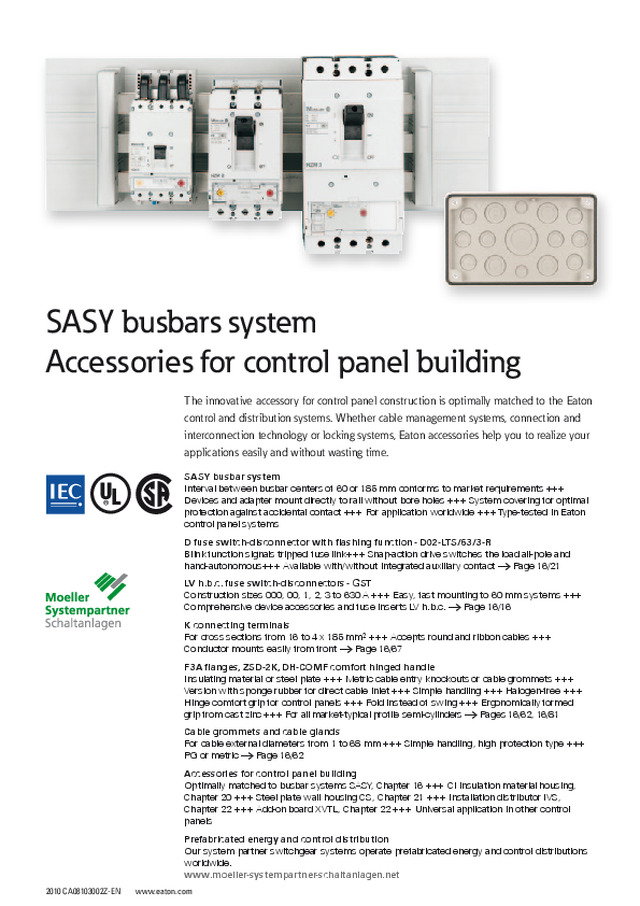
2010 CA08103002Z-EN www.eaton.com SASY busbar system Interval between busbar centers of 60 or 185 mm conforms to market requirements +++ Devices and adapter mount directly to rail without bore holes +++ System covering for optimal protection against accidental contact +++ For application worldwide +++ Type-tested in Eaton control panel systemsD fuse switch-disconnector with flashing function - D02-LTS/63/3-R Blink function signals tripped fuse link+++ Snap-action drive switches the load all-pole and hand-autonomous+++ Available with/without integrated auxiliary contact → Page 16/21LV h.b.c. fuse switch-disconnectors - GST Construction sizes 000, 00, 1, 2, 3 to 630 A +++ Easy, fast mounting to 60 mm systems +++ Comprehensive device accessories and fuse inserts LV h.b.c. → Page 16/16K connecting terminals For cross sections from 16 to 4 x 185 mm² +++ Accepts round and ribbon cables +++ Conductor mounts easily from front → Page 16/67F3A flanges, ZSD-2K, DH-COMF comfort hinged handle Insulating material or steel plate +++ Metric cable entry knockouts or cable grommets +++ Version with sponge rubber for direct cable inlet +++ Simple handling +++ Halogen-free +++ Hinge comfort grip for control panels +++ Fold instead of swing +++ Ergonomically formed grip from cast zinc +++ For all market-typical profile semi-cylinders → Pages 16/62, 16/81Cable grommets and cable glands For cable external diameters from 1 to 68 mm +++ Simple handling, high protection type +++ PG or metric → Page 16/62Accessories for control panel building Optimally matched to busbar systems SASY, Chapter 16 +++ CI insulation material housing, Chapter 20 +++ Steel plate wall housing CS, Chapter 21 +++ Installation distributor IVS, Chapter 22 +++ Add-on board XVTL, Chapter 22 +++ Universal application in other control panelsPrefabricated energy and control distribution Our system partner switchgear systems operate prefabricated energy and control distributions worldwide. www.moeller-systempartner-schaltanlagen.net The innovative accessory for control panel construction is optimally matched to the Eaton control and distribution systems. Whether cable management systems, connection and interconnection technology or locking systems, Eaton accessories help you to realize your applications easily and without wasting time. SASY busbars system Accessories for control panel building
SASY busbar system System overview 60 mm system 16/2 Ordering System for flat busbars 16/4 System for profile busbars 16/6 System covers 16/7 Terminals and connectors 16/9 Busbar adapters for NZM 16/14 Busbar adapters for PKZ and PKE 16/15 Complete range 7/22 Busbar adapters for MSC motor starters 8/26 Busbar fuse material 16/16 System overview Compact system 16/22 Ordering System for flat busbars 16/24 System covers 16/24 Terminals and connectors 16/25 Busbar adapters for NZM 16/27 Busbar adapters for PKZ and PKE 8/23 Busbar fuse material 16/27 System overview 185 mm system 16/28 Ordering System for flat and profiled busbars 16/30 Busbar fuse material 16/32 Terminals and connectors 16/34 KSX system, distribution board feeder system 16/38 Engineering Current-carrying capacity busbar support, 16/39 rigid busbarsShort-circuit strength busbar support 16/40 Selection data 16/41 Technical data System for flat and profiled busbars 16/42 Busbar fuse material 16/43 Dimensions System for flat busbars and profile busbars 16/50 System covers 16/51 Terminals and connectors 16/52 Busbar adapters for NZM 16/57 Busbar adapters for PKZ and PKE 7/40 Busbar adapters for MSC motor starters 8/45 Busbar fuse material 16/58 KSX system 16/61 Accessories for control panel building Ordering Cable management system 16/62 Cable inlet flanges 16/62 Cable glands 16/62 Ventilation cable glands 16/63 Pressure equalization plug 16/64 Cable grommets 16/64 Stepped cable grommets 16/64 Pressure compensating grommet 16/64 Cable ducts and accessories 16/65 Terminals and connectors 16/67 Terminals 160 - 1000 A and accessories 16/67 Insulated single terminal 32 – 100 A 16/70 Ultra-flat busbar terminals 100 - 800 A 16/70 Accessories for ultra-flat busbar terminals 16/71 Copper strip, isolated 16/72 Conductor supports for copper band isolated 16/66 Copper flat rails with/without pilot holes 16/73 DIN rails 16/73 Meters for door mounting , analog 16/74 Power factor meters (p.f. meter) 16/74 Voltmeter, class 1.5 16/74 Ammeters, class 1.5 16/75 Maximum bimetallic ammeter, class 3 16/78 Retaining frames for measurement devices 16/79 door mounting Meters for DIN rails, analog and digital 16/80 Closing and locking systems 16/81 Circuit diagram pockets 16/82 Control panel lighting 16/82 Door grounding set 16/83 Touch up paint 16/83 Blanking strips 16/83 Eye bolts 16/83 Meter rail 16/83 Engineering Conductor supports for insulated copper strip 16/84 Technical data Cable glands 16/85 Meters for DIN rails 16/85 analog 16/85 digital 16/86 Dimensions Cable glands 16/87 Connecting terminals 16/89 Meters 16/90 Closing and locking systems 16/90 SASY busbars system, accessories for control panel building 10 30 20 30 40 50 60 200 300 400 500 600 a b a [mm] [kA] I PK 10 4 30 10 40
16/2 Busbar system 60 mm system 2010 CA08103002Z-EN www.eaton.com SASY 60 mm systemSASY System overview 24 23 14 15 16 19 22 21 18 17 20 6 5 11 2 3 4 1 12 13 8 9 10 7
2010 CA08103002Z-EN www.eaton.com Busbar system 60 mm system SASY 16/3 System covers 1 Partitioning of busbars or terminals for increased personal safety.Different versions, for individual customization or ready to install in defined dimensions.For 3- and 4 pole systems.→ Page 16/8 Cover for empty sections, modular 2 Spare section cover can be cut to length.Clipped on simply and quickly to the support provided.For 3- and 4 pole systems→ Page 16/7 Cover for empty sections support 3 Simple push-fit, for all copper busbars.For 3- and 4 pole systems→ Page 16/7 Terminal plates 4 Terminal modules protected against direct contact, lockable.For commonly available connection cables and busbars.For 3- and 4 pole systems→ Page 16/7 Busbar end-to-end connectors 5 For interconnecting busbar systems.For flat and profiled busbars.→ Page 16/13 Universal conductor terminals 6 With integrated retaining spring.Captive fixing screw.Suitable for all copper, flat and profiled busbars.→ Page 16/12 Expansion terminals 7 For fitting to busbars without drillingCables can be inserted from the top simply and quickly.→ Page 16/10 Profiled busbars 11 Cross-sections 500, 720 and 1140 mm 2 . Tin-plated surface for low contact resistanceTin-plated copper busbars cut time needed to prepare contact points.→ Page 16/11 Double T profile busbar supports 9 Cross-sections 500 mm 2 (1250 A) and 720 mm 2 (1600 A) Very high short-circuit rating for greater system safety.Fewer supports required.Spacing between busbar centers 60 mm.→ Page 16/6 Terminal shroud 10 For covering the copper busbar ends for increased contact protection.→ Page 16/6 Flat busbars 8 12 x 5 up to 30 x 10 mm, Cu.→ Page 16/24 Busbar supports 12 For all commonly available flat busbars.Can be fitted to all busbar sizes using concertina system.For 3- and 4 pole systemsVersions for IEC and UL/CSA.Spacing between busbar centers 60 mm.→ Page 16/4 Terminal shroud 13 For covering the ends of flat copper busbars→ Page 16/4 Busbar adapters for PKZ and PKE 14 Mounting rails and connection cables prepared for motor starter combinations with PKZ, PKE or DILM.With combi-base suitable for 5 and 10 mm thick flat and profiled busbars.Versions with connection cables for spring-loaded terminals or without electrical contact.→ Page 7/22Two-row double adapter for specific applications, e.g. with fuses.→ Page 16/21Complete devices prefitted and wired for DOL starters.→ Page 8/26Complete devices prefitted and wired for reversing starters.→ Page 8/28 Busbar adapters for NZM 15 Innovative terminal design for rear connetion.For all commonly available flat busbars and for double T profile.For 3- and 4 pole systems.Conductors completely embedded for maximum safety.Easy mounting and terminal connection→ Page 16/14 LV h.b.c. fuse switch-disconnectors 16 Switching devices NH000, NH00, NH1, NH2 and NH3 up to 630 A.→ Page 16/16 D fuse switch-disconnectors without flashing function 17 Switch-disconnectors for D02 screw fuses.Clear contact position indication.Screw caps available as accessories.→ Page 16/21 D fuse switch-disconnectors with flashing function 17 Flashing function indicates blown fuse link.Switches the load on all poles and without touching by hand.With fuse plug, therefore no new screw caps required. Low heat dissipation.With contact position indicator.→ Page 16/21 D busbar mounting fuse devices 19 D02, DII and DIII with front and bottom plate supplied.→ Page 16/20 Fuse links 20 D01, D02, DII, DIII and C10.→ Page 19/47 Fuse adapters 21 D01, D02 cartridge ring adaptes, DII and DIII gage rings.→ Page 19/47 Screw caps 22 D01, D02, DII and DIII.→ Page 19/44 Disconnecting blades 23 Can be used instead of LV h.b.c. fuse links.Full contact blades. LV h.b.c. fuse links 24 Compact construction size up to 100 A; NH00 fuses can also used in NH000 devices.Fuse links NH00, NH1, NH2 and NH3 up to 630 A.High breaking capacity 120 kA.→ Page 19/53
16/4 60 mm system System for flat busbars 2010 CA08103002Z-EN www.eaton.com SASY SASYSystem for flat busbars Ordering Poles Rated opera-tional current For use with Part no.Article no. PriceSee price list Std. pack I e A Busbar supports • Thermoplast, silicone-free, chlorine-free• Halogen-free• Self-extinguishing to UL 94• RAL 7035• Creepage resistance CTI 200• Temperature-resistant up to 120 °C IEC busbar supports Can be fitted to all busbar sizes using concertina system.With internal screw holes. 3 630 12 x 5/1015 x 5/1020 x 5/1025 x 5/1030 x 5/10 BBS-3/FL 1) 2) 107066 10 off 4 630 BBS-4/FL138381 10 off UL busbar supports Can be fitted to all busbar sizes using concertina system.With internal screw holes. 3 630 12 x 5/1020 x 5/1030 x 5/10 BBS-3/FL-NA 1) 2)3) 107067 10 off PE/N busbar supports Can be fitted to all busbar sizes using concertina system.Can be mounted individually. 2 630 12 x 5/1015 x 5/1020 x 5/1025 x 5/1030 x 5/10 BBS-2/FL107069 10 off 1 630 BBS-1/FL107161 10 off Terminal shroud For covering busbars. – – BBS-3/FLBBS-3/FL-NA ES-BBS-3/FL 1) 2)3) 107068 10 off UL bottom plate • Silicone-free, chlorine-free• Temperature-resistant up to 110 °C• Self-extinguishing to UL 94 For use when air gap between busbars and mounting plate is not sufficient.1100 mm long. – – BBS-3/FLBBS-3/FL-NA BBC-BT-NA 1) 2) 107172 2 off Notes 1) Current load → Page 16/39 2) Current load → Page 16/39 Information relevant for export to North America Product Standards UL508A; CSA-C22.2 No. 14; IEC 60439-1; CE marking UL File No. E300273 UL CCN NMTR, NMTR7 CSA File No. 236217 CSA Class No. 3211-37 NA Certification UL Listed, CSA certified Conditions of Acceptability Refer to approbation report Specially designed for NA NoYes 3) Suitable for Feeder circuits Max. Voltage Rating 600 V AC BBS-..., BBC-... HPL16004EN
60 mm system System for flat busbars 2010 CA08103002Z-EN www.eaton.com SASY 16/5 Poles Rated opera-tional current For use with Part no.Article no. PriceSee price list Std. pack I e A Busbar shrouds • Silicone-free, chlorine-free• Temperature-resistant up to 110 °C• Self-extinguishing to UL 94 1000 mm long. – – 12 x 515 x 520 x 525 x 530 x 5 BBC-FL5107173 10 off – – 12 x 1015 x 1020 x 1025 x 1030 x 10 BBC-FL10107174 10 off Rated operational current Copper bars Length Copper factor 1) Material Part no.Article no. PriceSee price list Std. pack I e A mm mm Flat busbars 160 12 x 5 1500 Copper, tinned CU12X5034121 10 off 160 12 x 5 2250 Copper, tinned CU12X5-2250005093 10 off 250 20 x 5 1500 Copper, tinned CU20X5044092 10 off 250 20 x 5 2250 Copper, tinned CU20X5-2250007466 10 off 460 20 x 10 1500 Copper, tinned CU20X10041719 5 off 460 20 x 10 2250 Copper, tinned CU20X10-2250009839 5 off 630 30 x 10 1500 Copper, blank CU30X10051211 1 off Notes 1) Calculation of material surcharge → Chapter 23 Information relevant for export to North America Product Standards UL508A; CSA-C22.2 No. 14; IEC 60439-1; CE marking UL File No. E300273 UL CCN NMTR, NMTR7 CSA File No. 236217 CSA Class No. 3211-37 NA Certification UL Listed, CSA certified Conditions of Acceptability Refer to approbation report Specially designed for NA ✓ Suitable for Feeder circuits Max. Voltage Rating 600 V AC BBS-..., CU...X HPL16005EN
16/6 60 mm system System for profile busbars 2010 CA08103002Z-EN www.eaton.com SASY SASYSystem for profile busbars Poles Rated opera-tional current For use with Copper factor Part no.Article no. PriceSee price list Std. pack I e A Busbar supports Double T profile busbar supports • Thermoplast, silicone-free, chlorine-free• Halogen-free• Self-extinguishing to UL 94• RAL 7035• Creepage resistance CTI 200• Temperature-resistant up to 120 °C For use as outer or center support.With internal screw holes. 3 1600 Double T profile BBS-3/PR 1) 4) 107162 3 off Suitable for assembly of PE or N bar.With internal screw holes. 1 1600 Double T profile BBS-1/PR 3) 107165 10 off Terminal shroud For shrouding busbar systems. – – BBS-3/PR ES-BBS-3/PR 4) 107164 4 off UL bottom plate • Silicone-free, chlorine-free• Temperature-resistant up to 110 °C• Self-extinguishing to UL 94 For use when air gap between busbars and mounting plate is not sufficient.1100 mm long. – – BBS-3/PR BBC-BT-NA 4) 107172 2 off Busbar shrouds • Silicone-free, chlorine-free• Temperature-resistant up to 110°C• Self-extinguishing to UL 94 1000 mm long. – – Double T profile BBC-CU-BAR/PR 4) 107175 5 off Profiled busbars E-CU double T profile busbar Tinned, cross-section 500 mm 2 , 2400 mm long. – 1250 For supports BBS-3/PR, BBS-1/PR, BBS-3/FL-185 CU-BAR-500/T 2) 4) 107166 32 off Tinned, cross-section 720 mm 2 , 2400 mm long. – 1600 For supports BBS-3/PR, BBS-1/PR, BBS-3/FL-185 CU-BAR-720/T 2) 4) 107167 32 off Notes 1) Current load → Page 16/39 2) Current load → Page 16/39 Calculation of material surcharge → Chapter 23 Information relevant for export to North America 3) 4) Product Standards UL508A; CSA-C22.2 No. 14; IEC 60439-1; CE marking UL File No. E307559 UL CCN NMTR2, NMTR8 CSA File No. 236217 CSA Class No. 3211-37 NA Certification UL Recognized, CSA certified Conditions of Acceptability Refer to approbation reportSuitable for Feeder circuits Max. Voltage Rating 600 V AC Product Standards UL508A; CSA-C22.2 No. 14; IEC 60439-1; CE marking UL File No. E300273 UL CCN NMTR, NMTR7 CSA File No. 236217 CSA Class No. 3211-37 NA Certification UL Listed, CSA certified Conditions of Acceptability Refer to approbation reportSpecially designed for NA YesSuitable for Feeder circuits Max. Voltage Rating 600 V AC BBS-..., BBC-..., CU-BAR-... HPL16006EN
60 mm system System covers 2010 CA08103002Z-EN www.eaton.com SASY 16/7 SASYSystem covers Part no.Article no. PriceSee price list Std. pack Description Spare covers Cover for empty sections, modular To cover the 60 mm system from the frontCan only be used with BBC-MRCOV1. 1100 mm long. BBC-RCOV1107178 2 off Empty sections cover support Suitable for all busbar thicknesses.Can only be used with BBC-RCOV1. – BBC-MRCOV1107179 10 off Empty sections cover for front panel cutouts Cover module for cutouts 54 mm wide.194 mm high. AM-195/54107963 15 off Separation profiles double T For 3 pole systems with BBS-3/PR 48 mm high.2400 mm long.Fixing on (profile) busbar support. BBC-CS48/PR107176 1 off 76 mm high.2400 mm long.Fixing on (profile) busbar support. BBC-CS76/PR107177 1 off Width Poles Rated operating current I e Terminal capacity For use with Cu factor 1) Part no.Article no. PriceSee price list Std. pack ⊙ Round conductor, solid Round conductor, flexible, with correctly crimped ferrule Round conductor, stranded Sectoral conductor, solid Sectoral conductor,, stranded Copper strip▃ Copper bar mm A mm Terminal plates • Silicone-free, chlorine-free• Temperature-resistant up to 120°C• Self-extinguishing to UL 94• Creepage resistance CTI 200 Spring-type terminal design. 20 3 80 1.5 - 16 mm 2 AWG 16 - AWG 6. 12 x 5/1015 x 5/1020 x 5/1025 x 5/1030 x 5/10Double T profile BBA-TP3/16107205 1 off The terminal can be removed for the connection of uncut conductors.Terminal area W x H 10 x 15 mm .Loop-through is possible. 54 300 6 - 50 mm 2 AWG 10 - AWG 2/0. 6 x 9 x 0.8 BBA-TP3/50107183 1 off The terminal can be removed for the connection of uncut conductors.Terminal area W x H 15 x 15 mm.Loop-through is possible. 81 440 35 - 120 mm 2 AWG 2 - MCM 250. 10 x 16 x 0.8 BBA-TP3/120107184 1 off Notes 1) Calculation of material surcharge → Chapter 23 Information relevant for export to North America Product Standards UL508A; CSA-C22.2 No. 14; IEC 60439-1; CE marking UL File No. E300273 UL CCN NMTR, NMTR7 CSA File No. 236217 CSA Class No. 3211-37 NA Certification UL Listed, CSA certified Conditions of Acceptability Refer to approbation reportSuitable for Feeder circuits Max. Voltage Rating 600 V AC BBC-..., BBA-TP HPL16007EN
16/8 60 mm system System covers 2010 CA08103002Z-EN www.eaton.com SASY SASYSystem covers Part no.Article no. PriceSee price list Std. pack Description System cover, complete For 3 pole systems 228 mm long. BBC-CS1107209 1 off 270 mm long. BBC-CS3138377 1 off For 4 pole systems 228 mm long. BBC-CS4138387 1 off System cover, modular • Silicone-free, chlorine-free• Temperature-resistant up to 120 °C• Self-extinguishing to UL 94 For 3 pole systems Cover for empty sections, front.1100 mm long. BBC-CS2-F107180 1 off Cover for empty sections, top/bottom1100 mm long. BBC-CS2-T/B107181 2 off Support for cover for empty sections.Each set contains one left and one right support bracket. BBC-MCS2107182 1 off For 4 pole systems Cover for empty sections, front.1100 mm long. BBC-CS4-F138384 1 off Cover for empty sections, top/bottom1100 mm long. BBC-CS4-T/B138383 2 off Support for cover for empty sections.Each set contains one left and one right support bracket. BBC-MCS4138382 1 off Information relevant for export to North America Product Standards UL508A; CSA-C22.2 No. 14; IEC 60439-1; CE marking UL File No. E300273 UL CCN NMTR, NMTR7 CSA File No. 236217 CSA Class No. 3211-37 NA Certification UL Listed, CSA certified Conditions of Acceptability Refer to approbation report Suitable for Feeder circuits Max. Voltage Rating 600 V AC BBC-... HPL16008EN
60 mm system Terminals and connectors 2010 CA08103002Z-EN www.eaton.com SASY 16/9 SASYTerminals and connectors Terminal areaW × H Width Poles Rated operating current I e Terminal capacity For use with Cu factor Part no.Article no. PriceSee price list Std. pack ⊙ Round conductor, solid Round conductor, flexible, with correctly crimped ferrule Round conductor, stranded Sectoral conductor, solid Sectoral conductor,, stranded Copper strip▃ Copper bar mm mm A mm Connection kit • Silicone-free, chlorine-free• Temperature-resistant up to 120°C• Self-extinguishing to UL 94• Creepage resistance CTI 200 Pole spacing adjustable.Fixing direct over busbar terminal.Includes shroud with adjustable width.Loop-through is possible. – 180 - 240 3 560 120 - 300 mm 2 MCM 300 - MCM 600. 20 x 5/1025 x 5/1030 x 5/10Double T profile BBA-TP3/300 1) 107185 1 off 32 x 25 180 - 240 800 Up to 10 x 32 x 1▃ 30 x 25 BBA-TP3/CU-BAND 1) 107186 1 off Adapted to Eaton NZM4.Fixing direct over busbar terminal.Loop-through is possible. 5 x 28 228 3 1600 Up to (2 x) 10 x 50 x 1Up to▃ (2 x) 50 x 10 30 x 10Double T profile CU-BAND BBA-TP3/1000 2)4) 107207 1 off Pole spacing adjustable.Fixing direct over busbar terminal.Includes shroud with adjustable width.Loop-through is possible. – 180 - 228 4 560 120 - 300 mm 2 MCM 300 - MCM 600. 20 x 5/1025 x 5/1030 x 5/10Double T profile BBA-TP4/300 3) 138385 1 off 32 x 25 180 - 228 800 Up to 10 x 32 x 1▃ 30 x 25 BBA-TP4/Copper strip 3) 138386 1 off Notes 1) Each set contains 3 pole pieces. 2) Equipment supplied: 1 x BBC-CS1, 3 x AKS1000. 3) Each set contains 3 pole pieces. 4) Calculation of material surcharge → Chapter 23 BBA-TP... HPL16009EN
16/10 60 mm system Terminals and connectors 2010 CA08103002Z-EN www.eaton.com SASY Terminal areaW × H Width Rated operating current I e Terminal capacity For use with Copper factor 1) Part no.Article no. PriceSee price list Std. pack ⊙ Round conductor, solid Round conductor, flexible, with correctly crimped ferrule Round conductor, stranded Sectoral conductor, solid Sectoral conductor,, stranded Copper strip▃ Copper bar mm mm A mm Expansion terminals Connects onto busbars without drilling Contacting of cable with busbar via cable bedding. – 38 480 35 - 150 mm 2 AWG2/0 - MCM 300. Directly clamped 12 x 5/1020 x 5/10 AKS150138374 6 off – 38 500 95 - 185 mm 2 AWG3/0 - MCM 350. Directly clamped 20 x 5/1025 x 5/1030 x 5/10Double T profile AKS185107195 6 off – 41 600 150 - 300 mm 2 MCM300 - MCM 600. Directly clamped AKS300107196 3 off Contacting of cable with busbar via contact block. 32 x 25 41 800 3 x 20 x 1up to2 x (10 x 32 x1)▃ 32 x 25 AKS-CU-BAND107197 3 off 55 x 28 72 1600 Up to (2 x) 10 x 50 x 1Up to▃ (2 x) 50 x 10 AKS1000107208 1 off 68 x 28 122 1600 Up to▃ (2 x) 60 x 10 30 x 10Double T profileTriple T profile AKS1200138375 3 off 105 x 28 122 1600 Up to▃ (2 x) 100 x 10 AKS2000138376 3 off Notes 1) Calculation of material surcharge → Chapter 23 Information relevant for export to North America Product Standards UL508A; CSA-C22.2 No. 14; IEC 60439-1; CE marking UL File No. E307559 UL CCN NMTR2, NMTR8 CSA File No. 236217 CSA Class No. 3211-37 NA Certification UL Recognized, CSA certified Conditions of Acceptability Refer to approbation reportSuitable for Feeder circuits Max. Voltage Rating 600 V AC AKS... HPL16010EN
60 mm system Terminals and connectors 2010 CA08103002Z-EN www.eaton.com SASY 16/11 Terminal areaW × H Width Rated operating current I e Terminal capacity For use with Copper factor 1) Part no.Article no. PriceSee price list Std. pack ⊙ Round conductor, solid Round conductor, flexible, with correctly crimped ferrule Round conductor, stranded Sectoral conductor, solid Sectoral conductor,, stranded Copper strip▃ Copper bar mm mm A mm Profile terminals Connects onto busbars without drilling When connecting laminated busbars in parallel, fit a spacer. – 82 1600 750 mm 2 , terminal area 51 x 5 - 28▃ Double T profile AKP750138364 3 off – 72 1600 800 mm 2 , terminal area 41 x 20 - 42▃ AKP800107198 3 off – 94 1600 900 mm 2 , terminal area 64 x 5 - 28▃ AKP900138365 3 off – 94 1600 1000 mm 2 , terminal area 51 x 20 - 42▃ AKP1000107199 3 off – 94 2000 1200 mm 2 , terminal area 64 x 20-42▃ AKP1200138366 3 off – 112 2500 1600 mm 2 , terminal area 81 x 20 - 42▃ AKP1600138367 3 off – 132 3000 2000 mm 2 , terminal area 101 x 20 - 42▃ AKP2000138368 3 off – 132 3200 3600 mm 2 , terminal area 101 x 23 - 45▃ AKP3600138369 3 off Notes 1) Calculation of material surcharge → Chapter 23 Information relevant for export to North America Product Standards UL508A; CSA-C22.2 No. 14; IEC 60439-1; CE marking UL File No. E307559 UL CCN NMTR2, NMTR8 CSA File No. 236217 CSA Class No. 3211-37 NA Certification UL Recognized, CSA certified Conditions of Acceptability Refer to approbation reportSuitable for Feeder circuits Max. Voltage Rating 600 V AC AKP... HPL16011EN
16/12 60 mm system Terminals and connectors 2010 CA08103002Z-EN www.eaton.com SASY Terminal areaW × H Width Rated operating current I e Terminal capacity For use with Part no.Article no. PriceSee price list Std. pack ⊙ Round conductor, solid Round conductor, flexible, with correctly crimped ferrule Round conductor, stranded Sectoral conductor, solid Sectoral conductor,, stranded Copper strip▃ Copper bar mm mm A mm Universal conductor Connection terminals With integrated retaining spring, open clamping area and captive terminal screw. 7.5 x 7.5 11.5 180 1.5 - 16 mm 2 AWG 14 - AWG 6. Directly clamped⊙ 8 x 6 x 0.5 All 5 mm thick flat busbars AKU16/5107187 100 off 10.5 x 11 15.5 270 4 - 35 mm 2 AWG 10 - AWG 2. Directly clamped⊙ 3 x 9 x 0.8or 6 x 9 x 0.8 AKU35/5107188 50 off 14 x 14 20.5 400 16 - 70 mm 2 AWG 4 - AWG 2/0. Directly clamped 2 x (3 x 9 x 0.8)or 6 x 9 x 0.8 AKU70/5107189 25 off 17 x 1 23.5 440 16 - 120 mm 2 AWG 4 - MCM 250. Directly clamped 4 x 16 x 0.8 or 6 x 16 x 0.8or 10 x 16 x 0.8 AKU120/5107190 25 off 7.5 x 7.5 11.5 180 1.5 - 16 mm 2 AWG 14 - AWG 6. Directly clamped⊙ 8 x 6 x 0.5 All 10 mm thick flat busbars AKU16/10107191 100 off 10.5 x 11 15.5 270 4 - 35 mm 2 AWG 10 - AWG 2. Directly clamped⊙ 3 x 9 x 0.8or 6 x 9 x 0.8 AKU35/10107192 50 off 14 x 14 20.5 400 16 - 70 mm 2 AWG 4 - AWG 2/0. Directly clamped 2 x (3 x 9 x 0.8)or 6 x 9 x 0.8 AKU70/10107193 25 off 17 x 15 23.5 440 16 - 120 mm 2 AWG 4 - MCM 250. Directly clamped 4 x 16 x 0.8or 6 x 16 x 0.8or 10 x 16 x 0.8 AKU120/10107194 25 off M8 x 8 bolts 30 490 Cable lugs M8 All 10 mm thick flat busbarsDouble T profile AKU-M8/10138362 20 off M10 x 10 bolts 38 630 Cable lugs M10 AKU-M10/10138361 6 off Information relevant for export to North America Product Standards UL508A; CSA-C22.2 No. 14; IEC 60439-1; CE marking UL File No. E307559 UL CCN NMTR2, NMTR8 CSA File No. 236217 CSA Class No. 3211-37 NA Certification UL Recognized, CSA certified Conditions of Acceptability Refer to approbation reportSuitable for Feeder circuits Max. Voltage Rating 600 V AC AKU... HPL16012EN
60 mm system Terminals and connectors 2010 CA08103002Z-EN www.eaton.com SASY 16/13 Plate terminals – 50 630 – All 10 mm thick flat busbars PK900138378 3 off Connection terminals Contacting of cable with busbar via cable bedding. 48 630 95 - 300 mm 2 30 x 10Double T profile Triple T profile AK300138363 3 off Width For use with Copper factor 1) Part no.Article no. PriceSee price list Std. pack mm Busbar end-to-end connectors For hole-less connection of identical busbars. For the same flat copper barsRated operating current 630 A System spacing 100 - 110 mm.Max. permissible busbar offset 1 mm. 38 12 x 5/1015 x 5/1020 x 5/10 BBT-CU12-20X5/10-38138379 12 off 150 BBT-CU12-20X5/10-150107200 3 off System spacing 50 - 60 mm.Max. permissible busbar offset 5 mm. 40 BBT-CU20-30X5/10-40138380 6 off 95 BBT-CU20-30X5/10-95107201 3 off System spacing 100 - 110 mm.Max. permissible busbar offset 5 mm. 150 BBT-CU20-30X5/10-150107202 3 off For differing and same double T profile busbars.Rated operating current 1600 A System spacing 9 - 20 mm.Max. permissible busbar offset 2 mm. 50 Double T profile BBT-CU-BAR500/720-50107203 6 off System spacing 100 - 110 mm.Max. permissible busbar offset 5 mm. 150 BBT-CU-BAR500/720-150107204 3 off Notes 1) Calculation of material surcharge → Chapter 23 Terminal areaW × H Width Rated operating current I e Terminal capacity For use with Part no.Article no. PriceSee price list Std. pack ⊙ Round conductor, solid Round conductor, flexible, with correctly crimped ferrule Round conductor, stranded Sectoral conductor, solid Sectoral conductor,, stranded Copper strip▃ Copper bar mm mm A mm BBT-CU... HPL16013EN
16/14 60 mm system Busbar adapters for NZM 2010 CA08103002Z-EN www.eaton.com SASY SASYBusbar adapters for NZM Number of poles Rated opera-tional current Adapter width For use with Copper factor 9) Part no.Article no. PriceSee price list Std. pack I e A mm Component adapters for circuit-breakers and switch-disconnectors For installation on flat copper busbars 12 – 30 x 5 – 10, double T and triple T profileRated operating voltage U e : 690 V • Temperature-resistant up to 120 °C• Self-extinguishing to UL 94• Creepage resistance CTI 200 3 pole 160 90 NZM1,PN1,N(S)1 NZM1-XAD160 7) 104554 1 off 1) 250 106 NZM2,PN2,N(S)2 NZM2-XAD250 7) 104555 1 off 2) 630 140 NZM3,PN3,N3 NZM3-XAD630107206 1 off 3) 4 pole 250 140 NZM2, PN2, N(S)2NZM2(-4), PN2(-4), N(S)2(-4) NZM2-4-XAD250138388 1 off 5) 630 185 NZM3, PN3, N(S)3NZM3(-4), PN3(-4), N3(-4) NZM3-4-XAD630138389 1 off 4) Connection blocks for component adapters For NZM2, NZM3 circuit-breakers 3 pole 250 NZM2, PN2, N(S)2 NZM2-XKR4 8) 281666 1 off 6) 3 pole 630 NZM3, PN3, N(S)3 NZM3-XKR13 8) 281668 1 off 4 pole 250 NZM2-4, PN2-4, N(S)2-4 NZM2-4-XKR4118907 1 off 4 pole 630 NZM3-4, PN3-4, N(S)3-4 NZM3-4-XKR13119020 1 off Notes 1) For switches with standard box terminal connection.Connection to the system at top using supplied connection cable.In conjunction with IP2X protection against contact with a fingerEnhanced contact protection on the switch output end possible.Latch fitting to busbar using combination fixing baseCombination fixing base for adjustment to 5 and 10 mm rail thickness, terminal capacity 6 x 9 x 0.8.Rated short-circuit switching capacity 35 kA at 480 V.Busbar must be de-energized for mounting. 2) Connection to the system from above or below through rear connection (+)NZM2-XKR4… Mounted with clamp and screw fixing.Rated short-circuit switching capacity 65 kA at 480 V, 50 kA at 600 V.Busbar must be de-energized for mounting. 3) Connection to the system from above or below through rear connection (+)NZM3-XKR13… Mounted with claw-type terminal.Rated short-circuit switching capacity 65 kA at 480 V, 50 kA at 600 V.Busbar must be de-energized for mounting. Reduction of rated operating current → Page 16/41 4) Connection to the system from above or below through rear connection (+)NZM3-4-XKR13… Mounted with clamp and screw fixing. 5) Connection to the system from above or below through rear connection (+)NZM2-4-XKR4… Mounted with clamp and screw fixing. 6) Part no. and part no. suffix include parts for one switch side at top or bottom (with NZM...-4-... top only). Required for component adapters NZM2-XAD and NZM3-XADO = for fitting at the topU = for fitting at the bottom Information relevant for export to North America 7) Product Standards UL508A; CSA-C22.2 No. 14; IEC 60439-1; CE marking UL File No. E300273 UL CCN NMTR, NMTR7 CSA File No. 236217 CSA Class No. 3211-37 NA Certification UL Listed, CSA certified Conditions of Acceptability Refer to approbation report Suitable for Feeder circuits Max. Voltage Rating 600 V AC 8) Product Standards UL489; CSA-C22.2 No. 5-09; IEC60947, CE marking NA Certification Request filed for UL and CSA Suitable for Refer to main component information 9) Calculation of material surcharge → Chapter 23 NZM...-XAD, NZM...-XKR HPL16014EN
60 mm system Busbar adapters for PKZ and PKE, accessories 2010 CA08103002Z-EN www.eaton.com SASY 16/15 SASYBusbar adapters for PKZ and PKE, accessories Rated operational voltage Conductor cross-section Adapter width For use with Support rail Part no.Article no. PriceSee price list Std. pack U e V AC mm Number Busbar adapters for PKZ and PKE Complete range → Chapter 7 For surface mounting to flat copper busbars with 60 mm between busbar centers, suitable for 5 mm and 10 mm busbar thickness and also double T profile.Mounted by latching onto de-energized busbar.Connecting cables – – – – BBA… – BBA-XLT-6-130116902 30 off – – – – BBA… – BBA-XLT-16-142116903 30 off Double adapters Rated operational current 35 A 690 AWG 10(6 mm²) 45 12x5/1015x5/1020x5/1025x5/1030x5/10 2 Z-SS-60-ADD/6-45288790 1 off 690 AWG 10(6 mm²) 54 12x5/1015x5/1020x5/1025x5/1030x5/10 2 Z-SS-60-ADD/6-54288791 1 off 690 AWG 10(6 mm²) 72 12x5/1015x5/1020x5/1025x5/1030x5/10 2 Z-SS-60-ADD/6-72288792 1 off 690 AWG 10(6 mm²) 81 12x5/1015x5/1020x5/1025x5/1030x5/10 2 Z-SS-60-ADD/6-81288793 1 off Information relevant for export to North America Product Standards UL 508A; CSA-C22.2 No. 14; IEC60439-1; CE marking UL File No. On request UL CCN On request CSA File No. On request CSA Class No. On request NA Certification UL Recognized, CSA certified BBA, Z-SS-60-ADD HPL16015EN
16/16 60 mm system Busbar fuse material 2010 CA08103002Z-EN www.eaton.com SASY SASYBusbar fuse material SASYBusbar fuse material Connection Spacing between busbar centers Rated operational current Max. fuse link For use with Part no.Article no. PriceSee price list Std. pack I e 500 V 690 V Size mm A A A LV h.b.c. fuse switch-disconnectors • Includes handguard top and bottom (except GST-160-40-60-AOU)• Mounting without holes• For surface mounting on busbars3 pole Box terminal1.5 - 50 mm 2 Bottom 60 100 100 – NH000 20 x 5/1030 x 5/10Double T profile LTS-100/C00/3-R284690 1 off Box terminal 1.5 - 70 mm 2 Top or bottom 405060 160 160 100 NH00 20 x 5/1025 x 5/1030 x 5/10Double T profile GST00-160-40-60-AOU 1) 224550 1 off Screw M10Top 60 250 250 200 NH1 20 x 5/1025 x 5/1030 x 5/10Double T profile GST1-AO107250 1 off 60 400 400 315 NH2 GST2-AO107252 1 off 60 630 630 500 NH3 GST3-AO107254 1 off Screw M10Bottom 60 250 250 200 NH1 20 x 5/1025 x 5/1030 x 5/10Double T profile GST1-AU107251 1 off 60 400 400 315 NH2 GST2-AU107253 1 off 60 630 630 500 NH3 GST3-AU107255 1 off Size Rated operating voltage For use with Part no.Article no. PriceSee price list Std. pack Notes U e V Handguard for switch-disconnectors Provides additional protection for operator during actuation of fuse switch-disconnector 00 – GST00-160-… BS-SET-GST00107955 1 off One set contains handguard top and bottom. Notes 1) Without handguard.Order optional handguard BS-SET-GST00 → Page 16/16LV h.b.c. fuse links → Page 19/53 LTS, GST... HPL16016EN
60 mm system Busbar fuse material 2010 CA08103002Z-EN www.eaton.com SASY 16/17 SASYBusbar fuse material Size Rated operating voltage For use with Part no.Article no. PriceSee price list Std. pack Notes U e V Cover with fuse monitoring for fuse switch-disconnectors • Operation indicator 1 green LED• Fuse failure indication 3 red LEDs (F1, F2, F3)• Fault indication through relay contacts (floating)• Not for 1-phase application. 00 400 - 690 GST00…-A… GST00-DSI107956 1 off – 1 400 - 690 GST1-A… GST1-DSI107957 1 off – 2 400 - 690 GST2-A… GST2-DSI107958 1 off – 3 400 - 690 GST3-A… GST3-DSI107959 1 off – GST... HPL16017EN
16/18 60 mm system Busbar fuse material 2010 CA08103002Z-EN www.eaton.com SASY Terminal range For use with Part no.Article no. PriceSee price list Std. pack Notes Sets of prism terminals 1 x (70 - 150) mm² Cu/Al GSU1, GST…1 PSK1038734 1 off One set contains 3 prism terminals. 1 x (120 - 240) mm² Cu/Al GSU2, GST…2 PSK2043480 1 x (120 - 300) mm² Cu/Al GSU3, GST…3 PSK3048226 Sets of double prism terminals 2 x (70 - 95) mm² Cu/Al GSU1, GST…1 PSK12041107 1 off One set contains 3 double prism terminals 2 x (120 - 150) mm² Cu/Al GSU2, GST…2 PSK22045853 2 x (120-240) mm² Cu/Al GSU3, GST…3 PSK32050599 Box terminals 25 - 150 mm 2 Copper strip 6 x 16 x 0.8 mm GST…1 SK1-GS107960 3 off 3 required for each GST.... 25 - 240 mm 2 Copper strip 10 x 16 x 0.8 mm GST…2 SK2-GS107961 25 - 300 mm 2 Copper strip 11 x 21 x 1 mm GST…3 SK3-GS107962 PSK, SK HPL16018EN
60 mm system Busbar fuse material 2010 CA08103002Z-EN www.eaton.com SASY 16/19 Rated operational current Max. fuse link Size For use with Connection Part no.Article no. PriceSee price list Std. pack I e 400 V 690 V A A A LV h.b.c. fuse switches • With terminal compartment cover• Mounting without holes with spike type terminal Components supplied• NH-SLS-00/160-60(-SI): with box terminalsBusbar mounting• NH-SLS-00/160-60(-SI) 60 mm spacing between busbar centers Without fuse monitoring 160 160 160 00 12 x 5/1020 x 5/1025 x 5/1030 x 5/10Double-T-profiles Top or bottom NH-SLS-00/160-60 1) 106211 1 off With fuse monitoring 160 160 – 00 12 x 5/1020 x 5/1025 x 5/1030 x 5/10Double-T-profiles Top or bottom NH-SLS-00/160-60-SI 1) 106216 1 off Terminal shroud/size adapter for GST… For NH-SLS-00/160-60Size 00 Z-NH-SLS-KA106223 2 off Notes 2) LV h.b.c. fuse links → Page 19/53 NH-SLS, Z-NH-SLS HPL16019EN
16/20 60 mm system Busbar fuse material 2010 CA08103002Z-EN www.eaton.com SASY Rated opera-tional current Rated operating voltage Size Mounting width For use with Part no.Article no. PriceSee price list Std. pack I e U e A V AC mm D busbar mounting fuse devices Basic units • Includes contact protection shroud with front and bottom plate and designation label• Supplied empty without screw cap Cartridge ring adapter 63 400 E18, D 02 27 12 x 5/1020 x 5/1025 x 5/1030 x 5/10Double T profile D02-SO/63/3-R-27 1) 114315 10 off Cartridge ring adapter E18, D 02 36 Z-D02/R/3-36 1) 100663 60 off Cartridge ring adapter E18, D 02 54 Z-D02/R/3-54 1) 100664 40 off Gage ring 25 500 E 27, D II 45 DII-SO/25/3-R 2) 107965 10 off Gage screw 25 500 E 27, D II 45 DII-SO/25/3-R-PS 2) 110394 10 off Gage ring 63 690 E 33, D III 54 DIII-SO/63/3-R 3) 107966 10 off Gage screw 63 690 E 33, D III 54 DIII-SO/63/3-R-PS 3) 110395 10 off Side cover Can be fitted on right or leftCan be fitted to D…-SO/…/3-R(-PS) – – – – – DII-S0/…/3-R(-PS) SBS-RS60060541 10 off Kit for fitting over busbar supportsCan be fitted to D02-SO/63/3-R-27 – – – – 36 D02-S0/63/3-R-27 Z-D02-S-AB-SET100662 10 off Notes 1) A complete and functional fuse element consists of the basic unit • Fuse link → Page 19/47 • Fuse adapter → Page 19/47 • Screw cap → Page 19/47 2) A complete and functional fuse element consists of the basic unit • Fuse link → Page 19/43 • Fuse adapter → Page 19/44 • Screw cap → Page 19/44 3) A complete and functional fuse element consists of the basic unit • Fuse link → Page 19/43 • Fuse adapter → Page 19/44 • Screw cap → Page 19/44 D02, Z-D02, DII, DIII HPL16020EN
60 mm system Busbar fuse material 2010 CA08103002Z-EN www.eaton.com SASY 16/21 Rated opera-tional current Rated operational voltage Size Mounting width For use with Part no.Article no. PriceSee price list Std. pack I e U e A V AC mm D fuse switch-disconnectors without flashing function • 3 pole• Including contact protective shroud with front and bottom plate• Delivered empty and without screw cap Gage ring 63 400 E18, D 02 36 20 x 5/1030 x 5/10Double T profile D02-S/63/3-RS 1) 284649 1 off D fuse switch-disconnectors with flashing function • The flashing function indicates a blown fuse link• Supplied empty, without cartridge ring adapters and fuse links• Retaining springs for D01 fuse links or 10x38 cylindrical fuse links supplied• Contact position indicator• Fuse plug without screw cap• Switches the load on all poles and without touching by hand• D02-LTS/63/3-R-HK with integrated auxiliary contact• Sealable and lockable – 32 400 C10x38 27 12 x 5/1015 x 5/1020 x 5/1025 x 5/1030 x 5/10Double T profile D02-LTS/63/3-R114316 3 off – 63 400 E18, D02 27 D02-LTS/63/3-R-HK114318 3 off Notes 1) A complete and functional fuse element consists of the basic unit • Fuse link → Page 19/47 • Fuse adapter → Page 19/47 • Screw cap → Page 19/47 D02 HPL16021EN
16/22 Busbar system Compact System 2010 CA08103002Z-EN www.eaton.com SASY Compact SystemSASY System overview 5 6 2 3 4 10 9 11 12 13 14 15 16 17 8 7 1
2010 CA08103002Z-EN www.eaton.com Busbar system Compact System SASY 16/23 Terminal plates 1 Simple connection by contacting the conductor.Full contact protection.→ Page 16/25 Cover for empty sections, modular 2 Spare section cover can be cut to length.Clipped on simply and quickly to the support provided.Compact height.For 3 pole systems.→ Page 16/24 Empty sections cover support 3 Simple push-fit, for busbars 12 x 5/10.For 3 pole systems.→ Page 16/24 Busbar end-to-end connectors 4 For interconnecting busbar systems.For flat busbars.→ Page 16/26 Universal conductor Connection terminals 5 With integrated retaining spring.Captive fixing screw.Suitable for all copper, flat and profiled busbars.→ Page 16/26 Expansion terminals 6 For fitting to busbars without drillingCables can be inserted from the top simply and quickly.→ Page 16/25 Flat busbars 7 12 x 5 and 12 x 10 mm, Cu.→ Page 16/24 Busbar supports 8 Suitable for use with flat busbars 12 x 5/10.Compact height.For 3 pole systems.Spacing between busbar centers 60 mm.→ Page 16/24 Busbar adapters for PKZ and PKE 9 Mounting rails and connection cables prepared for motor starter combinations with PKZ, PKE or DILM.Compact height.→ Page 7/23 Busbar adapters for NZM 10 Safe termination.For 3 pole systemsConductors completely embedded for maximum safety.Easy mounting and terminal connection→ Page 16/27 LV h.b.c. fuse switch-disconnectors 11 Switching device NH000 up to 100 A.Simple changing of termination direction bottom/top.Compact height.→ Page 16/27 Disconnecting blades 12 Can be used instead of LV h.b.c. fuse links.Full contact blades. LV h.b.c. fuse links 13 Compact construction size up to 100 A, NH00 fuses can also be used in NH000 devices.→ Page 19/53 D busbar mounting fuse devices 14 D02, compact height.Box terminal for connecting cables up to 25 mm 2 . Integrated protection against direct contact→ Page 16/20 Fuse links 15 D.02→ Page 19/47 Gage pieces 16 Gage rings D02.→ Page 19/47 Screw cap 17 D.02→ Page 19/47
16/24 Compact System System for flat busbars, system covers 2010 CA08103002Z-EN www.eaton.com SASY System for flat busbars, system coversSASY Ordering Poles Rated opera-tional current For use with Part no.Article no. PriceSee price list Std. pack I e A Busbar supports Compact busbar support With removable contact element for adapting to the busbar size.With screw holes on inside and integrated end cover. 3 360 12 x 5/10 BBS-3/FL-C 1) 138370 10 off Busbar shrouds • Silicone-free, chlorine-free• Temperature-resistant up to 110 °C• Self-extinguishing to UL 94 1000 mm long. – – 12 x 515 x 520 x 525 x 530 x 5 BBC-FL5107173 10 off 1000 mm long. – – 12 x 1015 x 1020 x 1025 x 1030 x 10 BBC-FL10107174 10 off System covers Cover for empty sections, modularFor covering the Compact System from the front.Can only be used with BBC-MRCOV3-C. 1100 mm long. – – BBC-RCOV3-C138371 2 off Empty sections cover supportSuitable for 5 and 10 mm busbar thickness.Can only be used with BBBC-RCOV3-C. – – – 12 x 5/10 BBC-MRCOV3-C138372 10 off Rated operational current Copper bars Length Copper factor 2) Material Part no.Article no. PriceSee price list Std. pack I e A mm mm Flat busbars 160 12 x 5 1500 Copper, tinned CU12X5034121 10 off 160 12 x 5 2250 Copper, tinned CU12X5-2250005093 10 off Notes 1) Short-circuit strength → Page 16/40 2) Calculation of material surcharge → Chapter 23 Information relevant for export to North America Product Standards UL508A; CSA-C22.2 No. 14; IEC 60439-1; CE marking UL File No. E300273 UL CCN NMTR, NMTR7 CSA File No. 236217 CSA Class No. 3211-37 NA Certification UL Listed, CSA certified Conditions of Acceptability Refer to approbation reportSuitable for Feeder circuits Max. Voltage Rating 600 V AC BBC..., CU12X HPL16024EN
Compact System Terminals and connectors 2010 CA08103002Z-EN www.eaton.com SASY 16/25 SASYTerminals and connectors Terminal area W x H Width Poles Rated operating current Terminal capacity⊙ Round conductor, solid Round conductor, flexible, with correctly crimped ferrule Round conductor, stranded Sectoral conductor, solid Sectoral conductor,, stranded Copper strip▃ Copper bar For use with Part no.Article no. PriceSee price list Std. pack I e mm mm A mm Terminal plates The terminal can be removed for the connection of uncut conductors.Contacting of cable with busbar via cable bedding. – 90 3 480 35 - 150 mm 2 AWG 2 - MCM 300. 10 x 20 x 1 12 x 5/1015 x 5/1020 x 5/10 BBA-TP3/100-C138373 1 off Expansion terminals Contacting of cable with busbar via cable bedding. – 38 – 480 35 - 150 mm 2 AWG2/0 - MCM 300. Directly clamped 12 x 5/1020 x 5/10 AKS150138374 6 off Universal conductor Connection terminals 7.5 x 7.5 11.5 – 180 1.5 - 16 mm 2 AWG 14 - AWG 6. Directly clamped⊙ 8 x 6 x 0.5 All 5 mm thick flat busbars AKU16/5107187 100 off 10.5 x 11 15.5 – 270 4 - 35 mm 2 AWG 10 - AWG 2. Directly clamped⊙ 3 x 9 x 0.8or 6 x 9 x 0.8 AKU35/5107188 50 off 14 x 14 20.5 – 400 16 - 70 mm 2 AWG 4 - AWG 2/0. Directly clamped 2 x (3 x 9 x 0.8)or 6 x 9 x 0.8 AKU70/5107189 25 off 17 x 15 23.5 – 440 16 - 120 mm 2 AWG 4 - MCM 250. Directly clamped 4 x 16 x 0.8 or 6 x 16 x 0.8or 10 x 16 x 0.8 AKU120/5107190 25 off Information relevant for export to North America Product Standards UL508A; CSA-C22.2 No. 14; IEC 60439-1; CE marking UL File No. E307559 UL CCN NMTR2, NMTR8 CSA File No. 236217 CSA Class No. 3211-37 NA Certification UL Recognized, CSA certified Conditions of Acceptability Refer to approbation report Suitable for Feeder circuits Max. Voltage Rating 600 V AC BBA..., AKU..., AKS... HPL16025EN
16/26 Compact System Terminals and connectors 2010 CA08103002Z-EN www.eaton.com SASY Terminal area W x H Width Poles Rated opera- tional current Terminal capacity For use with Part no.Article no. PriceSee price list Std. pack ⊙ Round conductor, solid Round conductor, flexible, with correctly crimped ferrule Round conductor, stranded Sectoral conductor, solid Sectoral conductor,, stranded Copper strip▃ Copper bar I e mm mm A mm Universal conductor connection terminals 7.5 x 7.5 11.5 – 180 1.5 - 16 mm 2 AWG 14 - AWG 6. Directly clamped⊙ 8 x 6 x 0.5 All 10 mm thick flat busbars AKU16/10107191 100 off 10.5 x 11 15.5 – 270 4 - 35 mm 2 AWG 10 - AWG 2. Directly clamped⊙ 3 x 9 x 0.8or 6 x 9 x 0.8 AKU35/10107192 50 off 14 x 14 20.5 – 400 16 - 70 mm 2 AWG 4 - AWG 2/0. Directly clamped 2 x (3 x 9 x 0.8)or 6 x 9 x 0.8 AKU70/10107193 25 off 17 x 15 23.5 – 440 16 - 120 mm 2 AWG 4 - MCM 250. Directly clamped 4 x 16 x 0.8or 6 x 16 x 0.8or 10 x 16 x 0.8 AKU120/10107194 25 off M8 x 8 bolts 30 – 490 Cable lugs M8 All 10 mm thick flat busbarsDouble T profile AKU-M8/10138362 20 off M10 x 10 bolts 38 – 630 Cable lugs M10 AKU-M10/10138361 6 off Width Rated operating current For use with Part no.Article no. PriceSee price list Std. pack I e mm A End-to-end busbar econnectors For hole-less connection of identical busbars. For the same flat copper bars.System spacing 100 - 110 mm.Max. permissible busbar offset 1 mm. 38 630 12 x 5/1015 x 5/1020 x 5/10 BBT-CU12-20X5/10-38138379 12 off 150 BBT-CU12-20X5/10-150107200 3 off Information relevant for export to North America Product Standards UL508A; CSA-C22.2 No. 14; IEC 60439-1; CE marking UL File No. E307559 UL CCN NMTR2, NMTR8 CSA File No. 236217 CSA Class No. 3211-37 NA Certification UL Recognized, CSA certified Conditions of Acceptability Refer to approbation report Suitable for Feeder circuits Max. Voltage Rating 600 V AC AKU..., BBT-CU12... HPL16026EN
Compact System Busbar fuse material 2010 CA08103002Z-EN www.eaton.com SASY 16/27 SASYBusbar fuse material Poles Rated opera-tional current Adapter width For use with Copper factor 2) Part no.Article no. PriceSee price list Std. pack I e A mm Component adapters for circuit-breakers and switch-disconnectors For surface mounting on flat copper busbars 12 – 30 x 5 – 10, double T and triple T profileRated operating voltage U e : 690 V • Temperature-resistant up to 120 °C• Self-extinguishing to UL 94• Creepage resistance CTI 200 3 pole 160 90 NZM1,PN1,N(S)1 0.23 NZM1-XAD160 1)2) 104554 1 off Poles Spacing between busbar centers Rated operational current Max. fuse link Size For use with Part no.Article no. PriceSee price list Std. pack I e 500 V 690 V mm A A A LV h.b.c. fuse switch-disconnectors For surface mounting on busbars 3 pole 60 100 100 100 NH00(0) (max. 21 mm width) – FCFSDNH000BBC60-3 4) 139533 1 off Rated opera-tional current Rated operational voltage Size Width For use with Part no.Article no. PriceSee price list Std. pack I e U e A V AC mm D busbar mounting fuse devices Basic units Latch mechanism for push-fitting on busbar.Gage ring 63 400 E18 D02 36 12 x 5/10 FCFBD02BBC60-3-36 3) 139532 6 off Notes 1) For switches with standard box terminal connection.Connection to the system at top using supplied connection cable.In conjunction with IP2X protection against contact with a fingerEnhanced contact protection on the switch output end possible.Latch fitting to busbar using combination fixing baseCombination fixing base for adjustment to 5 and 10 mm rail thickness, terminal capacity 6 x 9 x 0.8.Rated short-circuit switching capacity 35 kA at 480 V.Busbar must be de-energized for mounting. 2) Calculation of material surcharge → hapter 23 3) A complete and functional fuse element consists of the basic unit • Fuse link → Page 19/47 • Fuse adapter → Page 19/47 • Screw cap → Page 19/47 4) LV h.b.c. fuse links → Page 19/53 Information relevant for export to North America Product Standards UL508A; CSA-C22.2 No. 14; IEC 60439-1; CE marking UL File No. E300273 UL CCN NMTR, NMTR7 CSA File No. 236217 CSA Class No. 3211-37 NA Certification UL Listed, CSA certified Conditions of Acceptability Refer to approbation report Suitable for Feeder circuits Max. Voltage Rating 600 V AC NZM1-XAD, FCF... HPL16027EN
16/28 Busbar system 185 mm system 2010 CA08103002Z-EN www.eaton.com SASY 185 mm systemSASY System overview 11 6 1 2 10 12 4 3 7 5 9 8
2010 CA08103002Z-EN www.eaton.com Busbar system 185 mm system SASY 16/29 LV h.b.c. fuse switches 250 up to 630 A 1 Spacing between busbar centers 185 mm.Prepared for current transformer.Top or bottom outgoer possible.With/without electronic fuse monitoring.→ Page 16/32 LV h.b.c. fuse switches 160 A 2 Spacing between busbar centers 100 mm.Adaptable for 185 mm system.With/without electronic fuse monitoring.Top or bottom outgoer possible.→ Page 16/32 Busbar supports 3 Spacing between busbar centers 185 mm.Hole-less mounting of 30, 40, 50, to 120 x 10 mm flat busbars, double T and triple T profiled busbars.→ Page 16/31 Adapters 4 Adapts NH00 fuse combination units to the 185 mm system.Single or double adapters.Prepared for current transformer.→ Page 16/33 Current transformer 5 Can be retrofitted at any time with all fuse combination units.No additional space required, simply swing in.→ Page 16/33 Disconnecting blades 6 Can be used instead of LV h.b.c. fuse links.Full contact blades. LV h.b.c. fuse links 7 High breaking capacity 120 kA.Fuse links NH00, NH1, NH2 and NH3 up to 630 A.→ Page 19/53 Profile terminals 8 Safe connection of flat copper busbars or multi-layer copper strip to profiled busbars.8 different construction sizes from 750 to 3600 mm 2 terminal area. → Page 16/35 Expansion terminals 9 For fitting to busbars without drilling.Cables can be inserted from the top simply and quickly.→ Page 16/34 Universal conductor terminals 10 With integrated retaining spring.Captive fixing screw.Suitable for all copper, flat and profiled busbars.→ Page 16/36 End-to-end busbar connectors 11 For interconnecting busbar systems.For flat and profiled busbars.→ Page 16/37 Flat busbars, profiled busbars 12 Profiled busbars with cross-sections 500, 720 and 1140 mm², and flat copper busbars up to 30 x 10 mm.Tin-plated copper busbars cut time needed to prepare contact points.Flat busbars→ Page 16/24 Profiled busbars→ Page 16/31
16/30 185 mm system System for flat and profiled busbars 2010 CA08103002Z-EN www.eaton.com SASY SASYSystem for flat and profiled busbars Ordering Poles Rated opera-tional current For use with Part no.Article no. PriceSee price list Std. pack I e A Busbar supports Double T/Triple T profile busbar supports • Thermoplast, silicone-free, chlorine-free• Halogen-free• Self-extinguishing to UL 94• RAL 7035• Creepage resistance CTI 200• Temperature-resistant up to 120 °C Can be fitted with NH-SLS…Hole-less mounting of busbars. 3 2500 30 x 1040 x 1050 x 1060 x 1080 x 10100 x 10120 x 10Double T profileTriple T profile BBS-3/FL-185107210 1 off Double T profile busbar supports • Thermoplast, silicone-free, chlorine-free• Halogen-free• Self-extinguishing to UL 94• RAL 7035• Creepage resistance CTI 200• Temperature-resistant up to 120 °C Suitable for surface mounting of PE or N bar.With internal screw holes. 1 1600 Double T profile BBS-1/PR107165 10 off PE/N busbar supports • Thermoplast, silicone-free, chlorine-free• Halogen-free• Self-extinguishing to UL 94• RAL 7035• Creepage resistance CTI 200• Temperature-resistant up to 120 °C Can be fitted to all busbar sizes using concertina system.Can be mounted individually. 2 630 12 x 5/1015 x 5/1020 x 5/1025 x 5/1030 x 5/10 BBS-2/FL107069 10 off Can be fitted to all busbar sizes using concertina system.Can be mounted individually. 1 630 12 x 5/1015 x 5/1020 x 5/1025 x 5/1030 x 5/10 BBS-1/FL107161 10 off Information relevant for export to North America Product Standards UL508A; CSA-C22.2 No. 14; IEC 60439-1; CE marking UL File No. E300273 UL CCN NMTR, NMTR7 CSA File No. 236217 CSA Class No. 3211-37 NA Certification UL Listed, CSA certified Conditions of Acceptability Refer to approbation report Suitable for Feeder circuits Max. Voltage Rating 600 V AC BBS-... HPL16030EN
185 mm system System for flat and profiled busbars 2010 CA08103002Z-EN www.eaton.com SASY 16/31 Poles Rated opera-tional current For use with Cu factor Part no.Article no. PriceSee price list Std. pack I e A Profiled busbars E-CU double T profile busbar Tinned, cross-section 500 mm 2 , 2400 mm long. – 1250 For supports BBS-3/PR, BBS-1/PR, BBS-3/FL-185 CU-BAR-500/T 1) 107166 32 off Tinned, cross-section 720 mm 2 , 2400 mm long. – 1600 For supports BBS-3/PR, BBS-1/PR, BBS-3/FL-185 CU-BAR-720/T 1) 107167 32 off E-CU triple T profiled busbars Tinned, cross-section 1140 mm 2 , 2400 mm long. – 2500 For supports BBS-3/FL-185, KSX-3…. CU-BAR-1140/T107168 10 off Busbar shrouds • Silicone-free, chlorine-free• Temperature-resistant up to 110 °C• Self-extinguishing to UL 94 1000 mm long. – – 12 x 1015 x 1020 x 1025 x 1030 x 10 BBC-FL10107174 10 off 1000 mm long. – – For double T profile BBC-CU-BAR/PR107175 5 off Notes 1) Current load → Page 16/39 Calculation of material surcharge → Chapter 23 Information relevant for export to North America Product Standards UL508A; CSA-C22.2 No. 14; IEC 60439-1; CE marking UL File No. E300273 UL CCN NMTR, NMTR7 CSA File No. 236217 CSA Class No. 3211-37 NA Certification UL Listed, CSA certified Conditions of Acceptability Refer to approbation report Suitable for Feeder circuits Max. Voltage Rating 600 V AC CU-BAR..., BBC... HPL16031EN
16/32 185 mm system Busbar fuse material 2010 CA08103002Z-EN www.eaton.com SASY SASYBusbar fuse material Rated operational current Max. fuse link Size For use with Connection Part no.Article no. PriceSee price list Std. pack I e 400 V 690 V A A A LV h.b.c. fuse switches • With terminal compartment cover• Mounting without holes with spike type terminalEquipment supplied• NH-SLS-00/160(-SI): with claw-type and box terminals• NH-SLS sizes 1, 2, 3: without claw-type and box terminalsBusbar mounting• For size 00:• NH-SLS-00/160-60(-SI) 100 mm spacing between busbar centers, hole-less or screw fixing• Sizes 1, 2, 3: 185 mm space between busbar centers, hole-less or screw fixing Without fuse monitoring 160 160 160 00 30 x 1040 x 1050 x 1060 x 1080 x 10100 x 10120 x 10Double T profileTriple T profile Top or bottom NH-SLS-00/160106210 1 off 250 250 250 1 NH-SLS-1/250106212 400 400 400 2 NH-SLS-2/400106213 630 630 630 3 NH-SLS-3/630106214 With fuse monitoring 160 160 160 00 30 x 1040 x 1050 x 1060 x 1080 x 10100 x 10120 x 10Double T profileTriple T profile Top or bottom NH-SLS-00/160-SI106215 1 off 250 250 250 1 NH-SLS-1/250-SI106217 400 400 400 2 NH-SLS-2/400-SI106218 630 630 630 3 NH-SLS-3/630-SI106219 NH-SLS, Z-NH-SLS HPL16032EN
185 mm system Busbar fuse material 2010 CA08103002Z-EN www.eaton.com SASY 16/33 SASYBusbar fuse material For use with/ transformer ratio Part no.Article no. PriceSee price list Std. pack K N A Adapters Single adapter 100/185 30 x 1040 x 1050 x 1060 x 1080 x 10100 x 10120 x 10Double T profileTriple T profile Z-NH-SLS-00-SAD106220 1 off Single adapter 100/185 for mounting without holes Z-NH-SLS-00-SAD-KR106222 1 off Double adapter 100/185 Z-NH-SLS-00-SADD106221 1 off Terminal shroud/size adapter for NH-SLS Size 00 for NH-SLS-00/160 Z-NH-SLS-KA106223 2 off Claw-type terminals For connection at bottom NH-SLS, size 1, 2, 3 Z-NH-SLS-KRU106224 3 off For connection at top NH-SLS, size 1, 2, 3 Z-NH-SLS-KRO106225 3 off V-terminals Up to 240 mm 2 for stranded sectoral conductor, up to 300 mm 2 for solid sectoral conductor For size 1, 2 NH-SLS, size 1, 2 Z-NH-SLS-1+2-VAK106226 3 off For size 3 NH-SLS, size 3 Z-NH-SLS--3VAK106227 3 off Terminal expansion for 2 cable lugs For size 1, 2 – Z-NH-SLS-1+2-AE106239 1 off For size 3 Z-NH-SLS--3AE106240 Device support with DIN rail for terminals etc. Cover – Z-NH-SLS-1+2+3-GTAB106231 1 off Lower section Z-NH-SLS-1+2+3-GT106230 Current transformer NH-SLS-00• Fit to Z-NH-SLS-00-SAD… with fixing clip Z-NH-SLS-00BC. NH-SLS size 1, 2, 3• Swing into the standard rail, no additional space requirement. • Mounting of claw-type terminals still possible• Fix current transformer cables with fixing clips Z‐NH‐SLS‐-1+2+3‐BC. 150/5 Z-WAS-150/5A-1106232 3 off 200/5 Z-WAS-200/5A-1106233 250/5 Z-WAS-250/5A-1106234 300/5 Z-WAS-300/5A-1106235 400/5 Z-WAS-400/5A-1106236 500/5 Z-WAS-500/5A-1106237 600/5 Z-WAS-600/5A-1106238 Fixing clip For fixing current transformer to adapterin 185 mm busbar system (size 00) – Z-NH-SLS-00-BC106229 3 off For fixing (current transformer) cables to rear of the LV h.b.c. rails of sizes 1, 2, 3 Z-NH-SLS-1+2+3-BC106228 100 off Z-NH-SLS, Z-WAS HPL16033EN
16/34 185 mm system Terminals and connectors 2010 CA08103002Z-EN www.eaton.com SASY SASYTerminals and connectors Terminal areaW × H Width Rated operating current I e Terminal capacity For use with Copper factor 1) Part no.Article no. PriceSee price list Std. pack ⊙ Round conductor, solid Round conductor, flexible, with correctly crimped ferrule Round conductor, stranded Sectoral conductor, solid Sectoral conductor,, stranded Copper strip▃ Copper bar mm mm A mm Expansion terminals For fitting to busbars without drilling Contacting of cable with busbar via cable bedding. – 38 480 35 - 150 mm 2 AWG2/0 - MCM 300. Directly clamped 12 x 5/1020 x 5/10 0.00 AKS150138374 6 off – 38 500 95 - 185 mm 2 AWG3/0 - MCM 350. Directly clamped 20 x 5/1025 x 5/1030 x 5/10Double T profile 0.00 AKS185107195 6 off – 41 600 150 - 300 mm 2 MCM300 - MCM 600. Directly clamped 0.00 AKS300107196 3 off Contacting of cable with busbar via contact block. 32 x 25 41 800 3 x 20 x 1to2 x (10 x 32 x1)▃ 32 x 25 0.00 AKS-CU-BAND107197 3 off 55 x 28 72 1600 Up to (2 x) 10 x 50 x 1Up to▃ (2 x) 50 x 10 0.20 AKS1000107208 1 off 68 x 28 122 1600 Up to▃ (2 x) 60 x 10 30 x 10Double T profileTriple T profile 0.00 AKS1200138375 3 off 105 x 28 122 1600 Up to▃ (2 x) 100 x 10 0.00 AKS2000138376 3 off Notes 1) Calculation of material surcharge → Chapter 23 Information relevant for export to North America Product Standards UL508A; CSA-C22.2 No. 14; IEC 60439-1; CE marking UL File No. E307559 UL CCN NMTR2, NMTR8 CSA File No. 236217 CSA Class No. 3211-37 NA Certification UL Recognized, CSA certified Conditions of Acceptability Refer to approbation reportSuitable for Feeder circuits Max. Voltage Rating 600 V AC AKS... HPL16034EN
185 mm system Terminals and connectors 2010 CA08103002Z-EN www.eaton.com SASY 16/35 Terminal areaW × H Width Rated operating current I e Terminal capacity For use with Copper factor 1) Part no.Article no. PriceSee price list Std. pack ⊙ Round conductor, solid Round conductor, flexible, with correctly crimped fer-rule Round conductor, stranded Sectoral conductor, solid Sectoral conductor,, stranded Copper strip▃ Copper bar mm mm A mm Profile terminals For fitting to busbars without drilling When connecting laminated busbars in parallel, fit a spacer. – 82 1600 750 mm 2 , terminal area 51 x 5 - 28▃ Double T profile AKP750138364 3 off – 72 1600 800 mm 2 , terminal area 41 x 20 - 42▃ AKP800107198 3 off – 94 1600 900 mm 2 , terminal area 64 x 5 - 28▃ AKP900138365 3 off – 94 1600 1000 mm 2 , terminal area 51 x 20 - 42▃ AKP1000107199 3 off – 94 2000 1200 mm 2 , terminal area 64 x 20-42▃ AKP1200138366 3 off – 112 2500 1600 mm 2 , terminal area 81 x 20 - 42▃ AKP1600138367 3 off – 132 3000 2000 mm 2 , terminal area 101 x 20 - 42▃ AKP2000138368 3 off – 132 3200 3600 mm 2 , terminal area 101 x 23 - 45▃ AKP3600138369 3 off Notes 1) Calculation of material surcharge → Chapter 23 Information relevant for export to North America Product Standards UL508A; CSA-C22.2 No. 14; IEC 60439-1; CE marking UL File No. E307559 UL CCN NMTR2, NMTR8 CSA File No. 236217 CSA Class No. 3211-37 NA Certification UL Recognized, CSA certified Conditions of Acceptability Refer to approbation reportSuitable for Feeder circuits Max. Voltage Rating 600 V AC AKP... HPL16035EN
16/36 185 mm system Terminals and connectors 2010 CA08103002Z-EN www.eaton.com SASY Terminal areaW × H Width Rated operating current I e Terminal capacity For use with Part no.Article no. PriceSee price list Std. pack ⊙ Round conductor, solid Round conductor, flexible, with correctly crimped ferrule Round conductor, stranded Sectoral conductor, solid Sectoral conductor,, stranded Copper strip▃ Copper bar mm mm A mm Universal conductor connection terminals With integrated retaining spring, open clamping area and captive terminal screw. 7.5 x 7.5 11.5 180 1.5 - 16 mm 2 AWG 14 - AWG 6. Directly clamped⊙ 8 x 6 x 0.5 All 10 mm thick flat busbars AKU16/10107191 100 off 10.5 x 11 15.5 270 4 - 35 mm 2 AWG 10 - AWG 2. Directly clamped⊙ 3 x 9 x 0.8or 6 x 9 x 0.8 AKU35/10107192 50 off 14 x 14 20.5 400 16 - 70 mm 2 AWG 4 - AWG 2/0. Directly clamped 2 x (3 x 9 x 0.8)or 6 x 9 x 0.8 AKU70/10107193 25 off 17 x 15 23.5 440 16 - 120 mm 2 AWG 4 - MCM 250. Directly clamped 4 x 16 x 0.8or 6 x 16 x 0.8or 10 x 16 x 0.8 AKU120/10107194 25 off M8 x 8 bolts 30 490 Cable lugs M8 All 10 mm thick flat busbarsDouble T profile AKU-M8/10138362 20 off M10 x 10 bolts 38 630 Cable lugs M10 AKU-M10/10138361 6 off Information relevant for export to North America Product Standards UL508A; CSA-C22.2 No. 14; IEC 60439-1; CE marking UL File No. E307559 UL CCN NMTR2, NMTR8 CSA File No. 236217 CSA Class No. 3211-37 NA Certification UL Recognized, CSA certified Conditions of Acceptability Refer to approbation reportSuitable for Feeder circuits Max. Voltage Rating 600 V AC AKU... HPL16036EN
185 mm system Terminals and connectors 2010 CA08103002Z-EN www.eaton.com SASY 16/37 Plate terminals – 50 630 – All 10 mm thick flat busbars PK900138378 3 off Width For use with Copper factor 1) Part no.Article no. PriceSee price list Std. pack mm End-to-end busbar onnectors For hole-less connection of identical busbars. For the same flat copper bars.Rated operating current 630 A System spacing 100 - 110 mm.Max. permissible busbar offset 1 mm. 150 12 x 5/1015 x 5/1020 x 5/10 BBT-CU12-20X5/10-150107200 3 off System spacing 50 - 60 mm.Max. permissible busbar offset 5 mm. 95 BBT-CU20-30X5/10-95107201 3 off System spacing 100 - 110 mm.Max. permissible busbar offset 5 mm. 150 BBT-CU20-30X5/10-150107202 3 off For differing and same double T profile busbars.Rated operating current 1600 A System spacing 9 - 20 mm.Max. permissible busbar offset 2 mm. 50 Double T profile BBT-CU-BAR500/720-50107203 6 off System spacing 100 - 110 mm.Max. permissible busbar offset 5 mm. 150 BBT-CU-BAR500/720-150107204 3 off Notes 1) Calculation of material surcharge → Chapter 23 Terminal areaW × H Width Rated operating current I e Terminal capacity For use with Part no.Article no. PriceSee price list Std. pack ⊙ Round conductor, solid Round conductor, flexible, with correctly crimped ferrule Round conductor, stranded Sectoral conductor, solid Sectoral conductor,, stranded Copper strip▃ Copper bar mm mm A mm PK..., BBT-CU... HPL16037EN
16/38 KSX system Distribution board feeder system 2010 CA08103002Z-EN www.eaton.com SASY SASYDistribution board feeder system Poles Rated opera-tional current For use with Part no.Article no. PriceSee price list Std. pack I e A Busbar supports KSX busbar support, end universal For use in type-tested power distribution systems xEnergy and distribution panels XVTL.Impulse withstand current 110 kAIncludes fixing bracket, fixing screws and supports for covers. 3/4 3200 30 x 10Double T profileTriple T profile KSX-34P-EXT138268 2 off KSX busbar support, center support For use in type-tested power distribution systems xEnergy and distribution panels XVTL.Includes fixing material. 3/4 2000 30 x 10Double T profileTriple T profile KSX-34P-MID138269 1 off 3 3200 Triple T profile KSX-3P-MID138360 1 off KSX HPL16038EN
Busbar system Characteristic curves for busbar supports, profiled busbars 2010 CA08103002Z-EN www.eaton.com SASY 16/39 Characteristic curves for busbar supports, profiled busbarsSASY Engineering Electrical load BBS-3/FL..., BBS-3/BR UL 508A DIN EN 13601 For untested busbar supports UL 508A stipulates a current-carrying capacity of 1000 A/inch 2 (1.55 A/mm 2 ) unless tests were carried out.This value can be higher if the product or application was tested accordingly.Eaton has carried out extensive tests in this area in order to provide the user with maximum benefits when using the 60 mm system. The 60 mm system can be used with higher rated operational currents than permitted by the default value. For example, a busbar support with the dimensions 30 x 10 can be loaded with 630 A instead of 465 A. The current carrying capacity values that exceed DIN 43671 specifications have been determined under normal operating conditions.The temperature of the busbars is normally favorably influenced by the fitting of busbar supports and the air circulation within the system.A correction factor k2 according to DIN 43671 can be determined, depending on the respective ambient air tempera-ture. The correction factor must be taken into account when conditions change or when the load is continuous. Otherwise, a higher load is possible if the components have a suitable temperature resistance.A 30 x 10 tinned busbar can be loaded to 630 A. At a load of 800 A, for example, a correction factor k2 of 1.3 is required. The graph shows that with this factor, and at an air temperature of 35°C, the busbars temperature rises to 85°C. CU-BAR-500/T Ambient temperature:① 30 °C② 35 °C③ 40 °CI U = rated uninter- rupted currentT S = busbar tempera- ture CU-BAR-720/T Ambient temperature:① 30 °C② 35 °C③ 40 °CI U = rated uninter- rupted currentT S = busbar tempera- ture a b c 1200 1000 800 1400 1600 1800 600 400 200 0 T S [°C] [A] I u 50 52.5 55 57.5 60 62.5 65 67.5 0 70 72.5 75 77.5 80 82.5 85 87.5 90 92.5 95 97.5 100 102.5 105 107.5 110 112.5 115 117.5 120 122.5 125 a b c 1500 1000 2000 2500 500 50 52.5 55 57.5 60 62.5 65 67.5 0 T S [°C] [A] I u 0 70 72.5 75 77.5 80 82.5 85 87.5 90 92.5 95 97.5 100 102.5 105 107.5 110 112.5 115 117.5 120 122.5 125 BBS, CU-BAR
16/40 Busbar system Characteristic curves of busbar supports 2010 CA08103002Z-EN www.eaton.com SASY Characteristic curves of busbar supportsSASY Short-circuit rating to IEC/EN 60439-1 BBS-3/FL BBS-3/PR BBS-3/FL-C ①②③ ④ I pk a 30 x 10 mm30 x 5 mm12 x 10 mm20 x 10 mm12 x 5 mm20 x 5 mm= Rated peak withstand current= Busbar support spacing ①②I pk a 720 mm 2 500 mm 2 = Rated peak withstand current= Busbar support spacing ①②I pk a 12 x 10 mm12 x 5 mm= Rated peak withstand current= Busbar support spacing Short-circuit strength to UL 845 BBS-3/FL-NA BBS-3/PR ① ② I rms a 30 x 5 mm30 x 10 mm12 x 5 mm20 x 5 mm12 x 10 mm20 x 10 mm= surge current (RMS)= Busbar support spacing ①②I rms a 500 mm 2 720 mm 2 = surge current (RMS)= Busbar support spacing 200 40 30 50 60 70 20 300 400 500 600 a b c d a [mm] [kA] I PK 40 30 50 60 70 80 90 300 500 700 900 1100 a b a [mm] [kA] I PK 10 30 20 30 40 50 60 200 300 400 500 600 a b a [mm] [kA] I PK 200 10 5 15 20 25 0 300 400 500 600 a b a [mm] [kA] I rms a b 200 10 5 15 20 25 0 400 600 800 100 a [mm] [kA] I rms BBS
Busbar system Selection data 2010 CA08103002Z-EN www.eaton.com SASY 16/41 Selection dataSASY Reduction of rated operating current Reduction of the rated operational current (derating) under particular ambient conditions (according to IEC 947) Device part no. Release type Derating coefficient20 °C 30 °C 40 °C 50 °C 60 °C 65 °C 70 °C Device adapter for circuit-breakers and switch-disconnectors (reference temperature 40 °C) NZM…3-630…+NZM3-XAD630 with XAD… 1 0.96 0.92 0.88 0.84 0.82 0.8 Notes To determine the maximum permissible current load at different ambient temperatures, refer to the derating coefficients shown in the table. Example: An NZM…3-…630… with a component adapter is to be used at an ambient temperature of 50 °C.What is the highest permissible rated operating current Ie?At 50 °C the derating coefficient is 0.88, which means that Ie = 630 A x 0.88 = 554.40 A.The NZM…3-…630… can therefore be used at an ambient temperature of 50 °C with a maximum Ie = 554.40 A. Possible combinations without bending the flat busbars Device GST00-160-40-60-AOU LTS-100/C00/3-R D02-S/63/3-RS D02-LTS/63/3-R(-HK) D02-SO/63/3-R-27Z-D02/R/3-… DII-SO/25/3-R… DIII-SO/63/3-R(-PS) Accessories BS-SET-GST00 - - - - SBS-RS60 SBS-RS60 CU 12 x 5/10 - - - x x x x 20 x 5/10 x x x x x x x 25 x 5/10 x - - x x x x 30 x 5/10 x x x x x x x Double T x x x x x x x Width mm 106 63 36 27 2736 - 54 45 54 NZM, GST, LTS, D02, DII, DIII
16/42 Busbar system Busbar supports, flat busbars, profiled busbars 2010 CA08103002Z-EN www.eaton.com SASY SASYBusbar supports, flat busbars, profiled busbars Technical data BBS-3/FL(-NA) BBS-4/FL BBS-3/PR BBS-3/FL-C BBS-3/FL-185 General Standards Type-tested to VDE 0660 Part 500, IEC/EN 60439-1 Mounting position Vertical, horizontal Material Material Thermoplast, silicone-free, chlorine-free Halogen-free Yes Yes Yes Yes Yes Flammability characteristics Self-extinguishing to UL 94 Color RAL 7035 RAL 7035 RAL 7035 RAL 7035 RAL 7035 Creepage resistance CTI 200 CTI 200 CTI 200 CTI 200 CTI 200 Temperature resistance °C 120 120 120 120 120 Contacts Rated insulation voltage U i V 3000 3000 3000 3000 3000 Rated operating voltage U e V 690 690 690 690 690 Rated frequency f Hz 50/60 50/60 50/60 50/60 50/60 Spacing between busbar centers mm 60 60 60 60 185 Rated uninterrupted current With temperature deviations, DIN 43671 stipulates that a correction factor k2 must be taken into account. with 12 × 5 mm busbar I u A 218 218 – 200 – with 15 × 5 mm busbar I u A 273 273 – – – with 20 × 5 mm busbar I u A 349 349 – – – with 25 × 5 mm busbar I u A 436 436 – – – with 30 × 5 mm basbar I u A 491 491 – – – with 12 × 10 mm busbar I u A 392 392 – 360 – with 20 × 10 mm busbar I u A 567 567 – – – with 30 × 10 mm basbar I u A 687 687 – – 630 with 500 mm 2 I u A – – 1003 – 950 with 720 mm 2 I u A – – 1281 – 1200 Ambient temperature °C 35 35 35 35 35 Busbar temperature °C 70 70 70 70 70 Rated peak withstand current with 12 × 5 mm busbar I pk kA 50 50 – 50 – with 20 × 5 mm busbar I pk kA 50 50 – – – with 25 × 5 mm busbar I pk kA 50 50 – – – with 30 × 5 mm basbar I pk kA 64 64 – – – with 12 × 10 mm busbar I pk A 56 56 – 55 – with 20 × 10 mm busbar I pk kA 56 56 – – – with 30 × 10 mm basbar I pk kA 73 73 – – 100 with 500 mm 2 I pk kA – – 72 – 100 with 720 mm 2 I pk kA – – 87 – 100 Short-circuit duration t ms 20 20 20 20 20 Distance between busbar supports a mm 250 250 500 250 400 For other intervals between busbar supports See Short-circuit rating characterstics, → Page 16/40 – CU… CU-BAR-500-TCU-BAR-720-T CU-BAR-1140/T General Standards EN 13061, UL 508 EN 13061, UL 508 EN 13061, UL 508 Contacts Rated uninterrupted current With temperature deviations, DIN 43671 stipulates that a correction factor k2 must be taken into account. T u = 35 °C and T s = 65 °C with 12 × 5 mm busbar I u A 200 – – with 20 × 5 mm busbar I u A 320 – – with 30 × 5 mm basbar I u A 450 – – with 12 × 10 mm busbar I u A 360 – – with 20 × 10 mm busbar I u A 520 – – with 30 × 10 mm basbar I u A 630 – – with 500 mm 2 I u A – 950 – with 720 mm 2 I u A – 1200 – 1140 mm 2 I u A – – 2500 BBS, CU...
Busbar system LV h.b.c. fuse switch-disconnectors 2010 CA08103002Z-EN www.eaton.com SASY 16/43 SASYLV h.b.c. fuse switch-disconnectors LTS-100/C00/3-R GST…00-160-40-60-AOU GST1-AO(AU) GST2-AO(AU) GST3-AO(AU) General Standards IEC/EN 60947-3 Climatic proofing Damp heat, constant, to IEC 60068-2-78; Damp heat, cyclical to IEC 60068-2-30 Ambient temperature °C -25 - +55 -25 - +55 -25 - +55 -25 - +55 -25 - +55 Installation altitude m Max. 2000 Max. 2000 Max. 2000 Max. 2000 Max. 2000 Distance between busbar centers m 60 60 60 60 60 Mounting position Vertical or horizontal Overvoltage category/pollution degree III/3 III/3 III/3 III/3 III/3 Touch protection at the front Operational status IP20 IP20 IP20 IP20 IP20 Front cover open IP10 IP10 IP10 IP10 IP10 Direction of incoming supply Any Lifespan, mechanical Operations 1700 1700 1700 1700 1700 Weight kg 0.57 0.93 4.4 5.3 6.6 Contacts Rated operational current 500 V AC/220 V DC I e A 100 160 250 400 630 690 V AC / 440 V DC I e A – 100 200 315 500 Rated frequency Hz 40 - 60 40 - 60 40 - 60 40 - 60 40 - 60 Rated conditional short-circuit current AC I q kA rms 50 50 50 50 50 DC I q kA rms 25 25 25 25 25 Utilization category AC-22B Rated making capacity 500 V AC A 300 480 750 1200 1890 690 V AC A – 300 600 945 1500 Rated breaking capacity 500 V AC A 300 480 750 1200 1890 690 V AC A – 300 600 945 1500 Utilization category DC-21B Rated making capacity 220 V DC/440 V DC A 400 150 300 475 750 Rated breaking capacity 220 V DC/440 V DC A 400 150 300 475 750 Lifespan, electrical Operations 300 300 200 200 200 Heat dissipation at I th , without fuse link 500 V AC W 11.5 6.9 12.9 27 52 690 V AC W – 2.7 8.3 16.7 32.8 220 V DC W 7.7 4.6 8.6 18 34.7 440 V DC W – 1.8 5.5 11.2 21.8 Rated insulation voltage U i V 500 750 750 750 750 Max. fuse link Construction size NH000 NH00 NH1 NH2 NH3 Max. rated operational current, gL/gG A 100 160 250 400 630 Max. permissible heat dissipation fuse link P v W 7.5 12 23 34 48 Terminal capacities Box terminal Stranded mm 2 1.5 - 50 1.5 - 70 – – – Copper strip Number of segments x width x thickness mm 6 x 9 x 0.8 6 x 9 x 0.8 – – – Flange connection Bolt diameter d mm – – M10 M10 M10 Cable lug mm 2 – – 1 x 25 - 100 1 x 25 - 100 1 x 25 - 100 Flat rail max. mm – – 30 x 10 30 x 10 30 x 10 Box terminal Stranded copper mm 2 – – 25 - 150 25 - 240 25 - 300 Copper strip Number of segments x width x thickness mm – – 6 x 16 x 0.8 10 x 16 x 0.8 11 x 21 x 1 Cable clamp Stranded aluminium/copper mm 2 – – 70 - 150 120 - 240 120 - 300 Double cable clamp Stranded aluminium/copper mm 2 – – 2 x (70 - 95) 2 x (120 - 150) 2 x (120 - 240) LTS-100..., GST...
16/44 Busbar system LV h.b.c. fuse switches 2010 CA08103002Z-EN www.eaton.com SASY SASYLV h.b.c. fuse switches NH-SLS-00/160-60 NH-SLS-00/160 NH-SLS-1/250 NH-SLS-2/400 NH-SLS-3/630 General Standards IEC/EN 60947-3 Climatic proofing Damp heat, constant, to IEC 60068-2-78Damp heat, cyclic, to IEC 60068-2-30 Ambient temperature °C -5 - +40 -5 - +40 -5 - +40 -5 - +40 -5 - +40 Installation altitude m Max. 2000 Max. 2000 Max. 2000 Max. 2000 Max. 2000 Distance between busbar centers mm 60 100 185 185 185 Number of poles/phases n 3 3 3 3 3 Mounting position Vertical, horizontal Overvoltage category/pollution degree III/3 III/3 III/3 III/3 III/3 Contact protection shroud at the front Operational status IP30 IP30 IP30 IP30 IP30 Front cover open IP10 IP10 IP10 IP10 IP10 Direction of incoming supply Any Lifespan, mechanical Operations 1400 1400 1400 800 800 Weight kg 1.46 1.37 5.2 6.3 7.0 Contacts Rated frequency f Hz 50 - 60 50 - 60 50 - 60 50 - 60 50 - 60 Rated insulation voltage U i V 1000 1000 1000 1000 1000 Rated operating mode Continuous operation ; with continuous operation of several adjaced devices the rated diversity factor to VDE 0660 part 500 / EN 60439-1, table 1 must be observed. Rated impulse withstand voltage U imp kV 8 8 12 12 12 Rated conditional short-circuit current AC I q kA rms 50 50 100 100 100 Utilization category AC-23B Rated operational voltage AC U e V AC 500/400 500/400 500 500 500 Rated operational current I e A 125/160 125/160 250 400 630 Utilization category AC-22B Rated operational voltage AC U e V AC 690 690 690 690 690 Rated operational current I e A 160 160 250 400 630 Utilization category AC-21B Rated operational voltage AC U e V AC 690 690 690 690 690 Rated operational current I e A 160 160 250 400 630 Heat dissipation at I th AC, without fuse link W 20 20 30 67 116 Lifespan, electrical Operations 200 200 200 200 200 Max. fuse link Construction size NH 00 00 1 2 3 Max. rated operational current gL/gG A 160 160 250 400 630 Max. permissible heat dissipation without fuse link P v W 12 12 23 34 48 Mechanical data Mounting on busbars Adapter for busbars – Z-…SADZ-…SADD – – – Combination base for busbars Directly on 12 - 30 x 5/10Double T profileTriple T profile – – – – Screw connection for busbars – M8 … x 5/10 mm M12… x 10 mm M12 … x 10 mm M12 … x 10 mm Terminal capacities Flange connection Bolt diameter d mm M8 M8 M10 M10 M12 Cable lug mm 2 1 x 70 1 x 70 1 x 120 1 x 240 2 x 185 Flat rail max. mm 20 x 8 20 x 10 30 x 10 30 x 10 30 x 10 Box terminal Stranded mm 2 1.5 - 70 1.5 - 70 – – – Flexible with ferrule 1) mm 2 1.5 - 70 1.5 - 70 – – – Copper strip Number of segments x width x thickness 6 x 9 x 0.8 6 x 9 x 0.8 – – – V-terminals Stranded mm 2 – 50 - 185 50 - 185 120 - 300 Sectoral conductor, stranded mm 2 – – 70 - 240 70 - 240 120 - 240 Sectoral conductor, solid mm 2 – 95 - 300 95 - 300 150 - 300 Terminal expansion Cable lugs n – – max.2 max.2 max.2 Notes The clearance to grounded parts must be at least 50/100 mm at the top and 25/50 mm on the sides with construction sizes 00/1-3.Technical data for fuse monitoring → Page 16/45 1) Ferrule with maximum cross-section with a correctly crimped ferrule. NH-SLS-...
Busbar system LV h.b.c. fuse switches accessories for LV h.b.c. fuse switch-disconnectors 2010 CA08103002Z-EN www.eaton.com SASY 16/45 SASYLV h.b.c. fuse switches accessories for LV h.b.c. fuse switch-disconnectors NH-SLS-…-SI General Standards IEC/EN 60255,VDE 0435 part 303 Climatic proofing Damp heat, constant, to IEC 60068-2-78Damp heat, cyclic, to IEC 60068-2-30 Ambient temperature °C -5 - +40 Installation altitude m Max. 2000 Contacts Rated operating voltage U e V 3 x 400 AC Voltage range V AC 0.8 … 1.1 x U e Rated frequency f Hz 50 - 60 Intrinsic consumption per phase (conductor) VA 2 (L2/L3) Rated insulation voltage U i V 400 Overvoltage category III Rated operating mode Continuous operation Rated impulse withstand voltage U imp kV 4 Relay contacts Standards EN 60947-5-1 Rated voltage U e V AC 250 Conventional thermal current I th A 4 Utilization category AC-15 Rated operating voltage U e V AC 230 Rated operational current AC-15 at 230 V I e A 1 Lifespan, electrical Operations 1.5 x 10 5 Lifespan, mechanical Operations 10 8 Max. admissible back-up fuse A gL 4 Terminal capacities Box terminal Solid mm 2 2 x 2.5 Flexible mm 2 2 x 1.5 Response/reset time ms 500 GST…-DSI Electrical data Standards IEC/EN 60255,VDE 0435 part 303 Rated operating voltage U e V AC 3 x 400 - 690 Voltage range V AC 0.9 … 1.1 x U e Rated frequency f Hz 50 - 60 Energy consumption P VA 1.5 (L2/L3) Rated insulation voltage U i V 690 Overvoltage category III Rated impulse withstand voltage U imp kV 6 Rated voltage U e V AC 250 Rated operational current I e A 8 A DC Inrush current A ≦ 15 Minimum switching load 5 V AC/DC, 300 mW, 5mA Max. switching power AC 1 VA 2000 250 V AC 15 VA 400 250 V AC 3 W 300 Lifespan, electrical Operations 80 x 10 3 (AC 1) Max. admissible back-up fuse 4 A gL/gG / PLSM-B4…-HS Mechanical data Terminals Lift terminals Terminal cross-section, flexible mm 2 0.25 - 1.5 Tightening torque of terminal screws Nm 0.5 - 0.6 Lifespan, mechanical Operations x 10 6 10 Response/reset time ms 500 Degree of protection IP20 Temperature range °C -10 … +55 Pollution degree 3 Terminal capacity mm² 0.25 - 1.5 NH-SLS-...-SI, GST...-DSI
16/46 Busbar system D busbar mounting fuse devices 2010 CA08103002Z-EN www.eaton.com SASY SASYD busbar mounting fuse devices D02-SO/63/3-R-27Z-D02/R/3… DII-SO/25/3-R(-PS) DIII-SO/63/3-R(-PS) General Standards Design according to IEC/EN 60269-1, VDE 0636 Part 301 Climatic proofing Damp heat, constant, to IEC 60068-2-78, Damp heat, cyclical to IEC 60068-2-30 Ambient temperature °C -25 - +55 -25 - +5535 normal temperature, at 55 with reduced operating current Mounting position Vertical or horizontal Electrical data Poles 3 3 3 Rated operating voltage U e V AC 400 500 690 U e V DC – – – Conditional rated short-circuit current tested with fuse links I q kA 50 50 50 Rated frequency f Hz 40-60 40-60 40-60 Rated operational current I e A 63 25 63 Conventional thermal current with fuse links I th A 63 25 63 Rated operating mode Continuous operation Overvoltage category IV III III Utilization category – – – Rated impulse withstand voltage U imp kV 6 4 4 Current heat dissipation per contact at I e W 0.5 0.4 3.34 Heat dissipation Heat dissipation per contact with fuse link at I e W 1.5 1.2 10 Max. permissible heat dissipation of fuse links W 5.5 4 7 Operating category – – – Mechanical data Standard front dimension mm 194 194 194 Enclosure width mm 201 200 200 Built-in width mm 27 45 54 Weight g 150 140 150 Electric thread E18 E27 E33 Mounting – – – Degree of protection Integrated IP20 IP20 IP20 Terminals Lift terminals Lift terminals Lift terminals Terminal capacity Solid mm 2 1.5 - 35 1.5 - 25 1.5 - 25 Pollution degree 3 3 3 Creepage resistance – – – D02-SO..., DII-SO..., DIII-SO...
Busbar system D fuse switch-disconnector 2010 CA08103002Z-EN www.eaton.com SASY 16/47 SASYD fuse switch-disconnector D02-S/63/3-RS D02-LTS/63/3-R(-HK) General Standards Design according to IEC/EN 60947-3 Climatic proofing Damp heat, constant, to IEC 60068-2-78, Damp heat, cyclical to IEC 60068-2-30 Ambient temperature °C -25 - +55 -25 - +55 Mounting position Vertical or horizontal Electrical data Poles 3 3 Rated operating voltage U e V AC 400 400 U e V DC – – Rated short-circuit current, tested with fuse links I q kA 50 63 Rated frequency f Hz 40-60 40-60 Rated operational current I e A 63 63 Conventional thermal current with fuse links I th A 63 63 Rated operating mode Continuous operation Rated short-circuit switching capacity I cn kA – 50 Overvoltage category III IV Utilization category AC 23 B AC 22 B Rated impulse withstand voltage U imp kV 8 6 Current heat dissipation per contact at I e W 2 1.5 Heat dissipation Heat dissipation per contact with fuse link at I e W 7.5 7 Max. permissible heat dissipation of fuse links W 5.5 5.5 Auxiliary contacts Changeover contacts Number – 5A/250 V AC Back-up fuse A gL – 2 A gLPLSM-B4/…-HS/CLS6-B4/…-HS Connection – Blade terminal sleeve 2.8 x 0.5 mm Mechanical data Standard front dimension mm 194 194 Enclosure width mm 212 226 Built-in width mm 36 27 Weight g 260 340 Electric thread E18 – Mounting Busbar with 60 mm clearance Degree of protection Integrated IP30 IP20/IP40 Terminals Lift terminals Lift terminals Terminal capacity Solid mm 2 1.5 - 25 1.5 - 35 Pollution degree 3 3 Creepage resistance – – D02-S..., D02-LTS...
16/48 Busbar system LV h.b.c. fuse switch-disconnector, D-type fuse base 2010 CA08103002Z-EN www.eaton.com SASY SASYD-type fuse bases, LV h.b.c. fuse switch-disconnector FCFSDNH000BBC60-3 General Standards IEC/EN 60947-3 Climatic proofing Damp heat, constant, to IEC 60068-2-78Damp heat, cyclic, to IEC 60068-2-30 Ambient temperature °C Installation altitude m Max. 2000 Mounting position Vertical or horizontal Overvoltage category/pollution degree III/3 Contact protection shroud at the front Operational status IP20 Front cover open IP10 Direction of incoming supply any Lifespan, mechanical Operations 1700 Weight kg 0.93 Contacts Rated operational current 690 V AC / 440 V DC I e A 100 Rated frequency f Hz 40 - 60 Rated conditional short-circuit current 690 V AC I q kA rms 50 440 V DC I q kA rms 25 Utilization category AC-22B Rated making capacity A 100 Rated breaking capacity A 100 Utilization category DC-21B Rated making capacity A 80 Rated breaking capacity A 80 Lifespan, electrical Operations 300 Heat dissipation at I th , without fuse link 690 V AC W W 2.7 440 V DC W 1.8 Rated insulation voltage U imp V 750 Max. fuse link Construction size Number of segments x width x thickness NH00(0) (max. 21 mm width) Max. rated operational current gL/gG A 100 Max. permissible heat dissipation of fuse link P v W 9 Terminal capacity Box terminal Flexible mm 2 2.5 - 50 Flexible with ferrule mm 2 1.5 - 50 (ferrule with maximum cross-section may not be possible) Solid mm 2 1.5 - 10 Stranded mm 2 16 - 50 Copper strip Number of segments x width x thickness mm 6 x 9 x 0.8; 9 x 9 x 0.8 FCFBD02BBC60-3-36 General Standards Type according to IEC/EN 60269-1, VDE 0636 Part 301 Climatic proofing Damp heat, constant, to IEC 60068-2-78Damp heat, cyclic, to IEC 60068-2-30 Ambient temperature °C -25 - +55 Mounting position Vertical or horizontal Contacts Poles 3 Rated operational voltage U e V AC 400 V AC Rated short-circuit current, tested with fuse links I q kA rms 50 Rated frequency f Hz 40 - 60 Rated operational current I e A 63 Conventional thermal current with fuse links I th A 63 Rated operating mode Uninterrupted operation Overvoltage category IV Rated impulse withstand voltage U imp kV 6 Current heat dissipation per contact at I e W 0.5 Heat dissipation per contact with fuse link at I e W 1.5 Max. permissible heat dissipation of fuse links P v W 5.5 Mechanical data Enclosure width mm 160 Built-in width mm 36 Weight g g 130 Electric thread E18 Degree of protection Integrated IP20 Terminals Lift terminals Terminal capacity Solid mm 2 1.5 - 25 Pollution degree 3 FCFS...-3, FCFB...-3-36
Busbar system 2010 CA08103002Z-EN www.eaton.com SASY 16/49 SASY Dimensions Busbar supports BBS-3/FL BBS-3/FL-NA BBS-2/FL BBS-1/FL 20 191 75 65 49.5 33 12 o 6.5 o 11 60 60 27 240 75 73.5 21 5 20 33 49.5 o 6.5 o 11.5 12 60 37 = = 150 164 BBS
16/50 Busbar system 2010 CA08103002Z-EN www.eaton.com SASY Busbar supports BBS-3/PR BBS-1/PR Terminal shroud ES-BBS-3/FL ES-BBS-3/PR UL bottom plate Busbar shroud BBC-BT-NA BBC-CU-BAR/PR 43 40 32 123 M6 60 60 200 50 75 25 32 104 50 60 15 30 166 31 5 200 100 6 6 240 75 73.5 21 5 30.7 39.7 77.9 71.1 BBS, ES-BBS, BBC
Busbar system 2010 CA08103002Z-EN www.eaton.com SASY 16/51 Profiled busbars Spare covers CU-BAR-500/T CU-BAR-720/T BBC-RCOV1 BBC-MRCOV1 Spare covers System covers AM-195/54 BBC-CS1 BBC-CS2-... BBC-CS3 BBC-CS4 10 4 30 10 40 10 6 30 10 40 60 160 66 155.5 60 35 60 5 54.5 2.6 1.6 1.8 3.6 14.6 R 1 7.1 54 204 195.5 196.5 194214228 F88 27.5 204 195 194 60 60 34 27.5 32 90 200 238 270 250 194 228 214 264 255 F 88 27.5 CU-BAR, AM, BBC-CS
16/52 Busbar system 2010 CA08103002Z-EN www.eaton.com SASY System covers BBC-CS48/PR BBC-CS76/PR Terminal plates BBA-TP3/16 BBA-TP3/50 BBA-TP3/120 6 48 123 215 6 76 123 215 194 200 60 34 60 20 28 32 54 32 88 194 200 94 60 60 81 32 88 194 200 94 60 60 BBC-CS, BBA-TP
Busbar system 2010 CA08103002Z-EN www.eaton.com SASY 16/53 Terminal kits BBA-TP3/300 BBA-TP3/CU-BAND CU-BAND BBA-TP3/1000 BBA-TP4/300 BBA-TP4/CU-BAND 51 153 180 - 240 F88 27.5 204 195 194214228 F88 27.5 204 195 194 228 214 264 244 255 F 88 F 87 51 204 27.5 BBA-TP
16/54 Busbar system 2010 CA08103002Z-EN www.eaton.com SASY Expansion terminals AKS185 AKS300 AKS CU-BAND AKS1000 AKS1200 AKS2000 Profile terminals AKP800 AKP1000 38 70 42 51 43 38 31 F61 41 85.5 42 51 43 41 33 10 41 85.5 53 51 43 41 33 10 F 85 72 13 - 28 55 80 F 85 b d c a Part no. a b c d AKS1200 85 80 68 13-38 AKS2000 122 80 105 13-38 89 a c b 45 Part no. a b c AKP800 118 72 41 AKP1000 103 94 64 AKS, AKP
Busbar system 2010 CA08103002Z-EN www.eaton.com SASY 16/55 Profile terminals AKP750 AKP900 AKP1200 AKP1600 AKP2000 AKP3600 Universal conductor connection terminals AKU16/5 AKU35/5 AKU70/5 AKU120/5 AKU16/10 AKU35/10 AKU70/10 AKU120/10 F 65 d b 39 c a Part no. a b c d AKP750 82 103 51 5-28 AKP900 94 103 64 5-28 AKP1200 94 118 64 20-42 AKP1600 112 118 81 20-42 AKP2000 132 118 101 20-42 AKP3600 132 154 101 23-45 5 22.5 25 11.5 7.5 5 29 35 15.5 10.5 5 32 42 20.5 14.5 5 36 55 20.5 14.5 10 22.5 25 11.5 7.5 10 29 35 15.5 10.5 10 32 42 20.5 14.5 10 36 55 23.5 17 AKP, AKU
16/56 Busbar system 2010 CA08103002Z-EN www.eaton.com SASY Universal conductor connection terminals AKUM8/10 AKUM10/10 End-to-end busbar connectors BBT-CU12-20X5/10-150 BBT-CU20-30X5/10-95 BBT-CU20-30X5/10-150 BBT-CU12-20X5/10-38 BBT-CU20-30X5/10-40 BBT-CU-BAR500/720-50 BBT-CU-BAR500/720-150 24 9 23 10 F 30 11.5 19.5 24.5 17.5 42 15 27.5 10 F 55 23.5 37 47 38 138 20 150 29 F 28 8.5 95 36 36.5 25 9 85 150 36.5 25 9 31 20 38 F 28 8.5 29 36.5 40 20 16 43 50 21 44 90 150 21 44 16 43 BBT-CU
Busbar system 2010 CA08103002Z-EN www.eaton.com SASY 16/57 SASY Component adapters for circuit-breakers and switch-disconnectors NZM1-XAD160 NZM2-XAD250 NZM3-XAD630 NZM2-4-XAD250 NZM3-4-XAD630 Double adapters Z-SS-60-ADD/6... 200 64 90 145 20 145 20 190 35 35 35 106 63 300 140 150 75 35 63 234 33 240 60 60 35 35 35 35 35 35 140 45 45 185 45 300 60 60 35 NZM...-XAD...
16/58 Busbar system 2010 CA08103002Z-EN www.eaton.com SASY LV h.b.c. fuse switch-disconnectors LTS-100/C00/3-R GST00-160-40-60-AOU GST1-A... GST2-A... GST3-A... Cover with fuse monitoring for fuse switch-disconnectors GST...-DSI 60 60 194 63 5 – 10 31.5 32 60 101 12 – 30 31.5 t s s 107 158 194 33 33 106 U 103 Part no. s t u GST0-160-40-60-AOU 40 12 5-10 50 20 5-15 60 20-30 5-10 60 60 h g b c F 30 k e d k a f Part no. a b c d e f g h k GST1-A... 184 230 322 70 121 16.5 115 104 58 GST2-A... 210 256 408 83 135 16.5 128 145 66 GST3-A... 254 270 434 98 149 9 135 156 82 a b Part no. Size a b GST00... NH00 90 123 GST1... NH1 120 151 GST2... NH2 135 166 GST3... NH3 145 176 LTS, GST
Busbar system 2010 CA08103002Z-EN www.eaton.com SASY 16/59 LV h.b.c. fuse switches NH-SLS-00/160 NH-SLS-00/160-60 NH-SLS-00/160-SI NH-SLS-00/160-60-SI NH-SLS-1/250 NH-SLS-1/250-SI NH-SLS-2/400 NH-SLS-2/400-SI NH-SLS-3/630 NH-SLS-3/630-SI ① NH-SLS-...-SI (with fuse monitoring) 84.5 50 31 67.5 120 289 100 100 133 a 288 455 26.526.5 F 238 a 610 33 5.5 33 100.5 50 15 83.5 136 26.526.5 289 455 a 610 60 60 135 6 33 5.5 33 a 290 50 58 99 197 148 145 14.5 764 185 a 908 a 429 185 2 285 57 322 258 16.5 580 610 F 457 NH-SLS
16/60 Busbar system 2010 CA08103002Z-EN www.eaton.com SASY D busbar mounting fuse devices D02-SO/63/3-R-27 Z-D02/R/3-36 Z-D02/R/3-54 ① Front plate support DII-SO/25/3-R(-PS) DIII-SO/63/3-R(-PS) Z-D02-S-AB-SET ① Front plate support ② Covered busbar support 60 60 27 27 10 178 193 194 201 34.5 14 32 h50 36 36 a 54 a 54 a 60 60 194 31.5 200 12-30 30 b 3235 Part no. a b DII-SO/25/3-R(-PS) 45 5-10 DIII-SO/63/3-R(-PS) 54 5-10 36 36 a a b D02, DII, DIII
Busbar system 2010 CA08103002Z-EN www.eaton.com SASY 16/61 D fuse switch-disconnector D02-LTS/63/3-R(-HK) D02-S/63/3-RS Busbar supports KSX-34P-EXT KSX-34P-MID 226 194 50 60 60 32 27 67 22 80 36 77 5 – 10 32 21 60 194 212 20 – 30 31.5 60 40 40 30 300 60 300 40 30 200 45 40 40 30 300 60 300 30 45 D02, KSX
16/62 Accessories for control panel building Flanges, cable glands 2010 CA08103002Z-EN www.eaton.com Flanges, cable glands Ordering Material Features Cable entry Part no.Article no. PriceSee price list Std. pack Flanges • With captive, sponge-rubber gasket• RAL 7035 Insulating material Blank plate - F3A-0074182 10 off Insulating material With metric cable entry knockouts 6 x M25/168 x M32/20, 4 x M16 F3A-4081301 10 off Insulating material With metric cable entry knockouts 2 x M208 x M25/164 x M32/201 x M50/32 F3A-8091468 10 off Insulating material With metric cable entry knockouts 12 x M20, 2 x M162 x M40/252 x M50/32 F3A-12076555 10 off Insulating material With metric cable entry knockouts 24 x M1613 x M20 F3A-34078928 10 off Insulating material With cable grommets 2 cables up to 70 mm ⌀ F3A-KTD083674 5 off Insulating material Sponge-rubber flange 40 cables, 10 – 13 mm ⌀ 4 cables, 17 - 21 mm ⌀ 2 cables, 27 - 30 mm ⌀ F3A-D010145 10 off Sheet steel Blank plate 2 mm, powder-spray paintedRAL 7035 - F3A-XP113426 1 off Insulating material Diaphragm flange for push-fitting cables, base RAL 9016, whiteFor cutouts 195 x 64 mm 14 x 11 mm ⌀8 x 15 mm ⌀2 x 28 mm ⌀ ZSD-2K/FLA272166 1 off Cable entry Drilling dimensions External diameter of cable For use with NYM/NYY cables, 4-core Part no.Article no. PriceSee price list Std. pack mm mm mm 2 Metric cable glands to EN 50262 • With lock nut and built-in strain relief• IP68 up to 5 bar, polyamide, halogen-free• Flammability classification V2 according to UL94• Color RAL 7035Cable screw gland M12 12.5 3 - 7 H03VV-F3 x 0.75 mm 2 , NYM 1 x 2.5 mm 2 V-M12215078 20 off M16 16.5 4.5 - 10 H05VV-F3 x 1.5 mm 2 , NYM 1 x 16/3 x 1.5 mm 2 V-M16215077 20 off M20 20.5 6 - 13 H05VV-F4 x 2.5/3 x 4 mm 2 , NYM 5 x 1.5/5 x 2.5 mm 2 V-M20206910 20 off M25 25.5 9 - 17 H05VV-F5 x 2.5/5 x 4 mm 2 , NYM 5 x 2.5/5 x 6 mm 2 V-M25206911 20 off M32 32.5 13 - 21 NYM 5 x 10 mm 2 V-M32206912 10 off M40 40.5 16 - 28 NYM 5 x 16 mm 2 V-M40209668 10 off M50 50.5 21 - 35 NYM 4 x 35/5 x 25 mm 2 V-M50206913 5 off M63 63.5 34 - 48 NYM 4 x 35 mm 2 V-M63214835 3 off F3A, V-M HPL16062EN
Accessories for control panel building Cable screw glands 2010 CA08103002Z-EN www.eaton.com 16/63 Cable screw glands Cable entry External diameter of cable For use with NYM/NYY cables, 4-core Part no.Article no. PriceSee price list Std. pack mm mm 2 Multiple gaskets for cable glands V-M... , metric M25 4 x 5 - 6 H03VV-F2 x 0.75/3 x 0.75 mm 2 MFD25215451 50 off M32 4 x 3.5 - 7 H03VV-F4 x 0.75 mm 2 MFD32215452 25 off Stoppers for unused openings in multiple gaskets MFD... M25 6 – MFV25-6215453 50 off M32 7 – MFV32-7215454 50 off Part no.Article no. PriceSee price list Std. pack Information relevant for export to North America PG cable glands • Conduit union and lock nut with grouding screw • Suitable for standard commercial conduit • Suitable for all enclosures CI…-NA → Page 20/9 ½ " STB1/2ZOLL045878 1 off Product Standards UL 467; UL 514B; CSA-C22.2 No. 18 UL File No. E23018, E3060 UL CCN DWTT, KDER CSA File No. LR 2884 CSA Class No. 4412-03, 4414-04 NA Certification UL Listed, CSA certified Conditions of Acceptability Only used in combination with CI-…-NA enclosuresSpecially designed for NA YesSuitable for Conduit, Tubing, and Cable Fittings, Grounding and Bonding Equipment Degree of Protection Refer to main component information See also Refer to basic component information ¾ " STB3/4ZOLL060116 1 " STB1ZOLL052997 1 ¼ " STB1-1/4ZOLL043505 1 ½ " STB1-1/2ZOLL041132 2 " STB2ZOLL002203 Cable entry Drilling dimensions External diameter of cable For use with NYM/NYY cables, 4-core Part no.Article no. PriceSee price list Std. pack mm mm mm 2 Ventilation cable glands • Color RAL 7035 Ventilation cable gland IP69 M20 20.5 6 - 13 H05VV-F 4 x 2.5/3 x 4 mm 2 , NYM 5 x 1.5/5 x 2.5 mm2 V-M20-VENT120814 1 off Ventilation cable glands IP56• Permeable to air, impermeable to dust• For the prevention of condensationFor use in the enclosure bottom or sides, polyamide, halogen-free M20 20.5 – – STB-M20F224557 20 off M25 25.5 – – STB-M25F224558 20 off MFD, MFV, STB-Zoll, V-M20-VENT, STB-M HPL16063EN
16/64 Accessories for control panel building Cable glands, cable grommets, pressure compensating grommets 2010 CA08103002Z-EN www.eaton.com Cable glands, cable grommets, pressure compensating grommets Cable entry Drilling dimensions External diameter of cable For use with NYM/NYY cables, 4-core Part no.Article no. PriceSee price list Std. pack mm mm mm 2 Pressure compensating plug Pressure compensating plug, IP66, metricColor RAL 7035 M40 x 1.5 – – – DAV-M40107225 2 off Pressure compensating plug, IP66, PGColor RAL 7032 PG29 – – – DA412079219 2 off Cable grommets, metric • IP66, with integrated push-through diaphragm• PE and thermoplastic elastomer, halogen-free• Color RAL 7035 M16 16.5 1 - 9 H03VV-F3 x 0.75 mm 2 , NYM 1 x 16/3 x 1.5 mm 2 KT-M16216983 100 off M20 20.5 1 - 13 H03VV-F3 x 0.75 mm 2 , NYM 5 x 1.5/5 x 2.5 mm 2 KT-M20207602 100 off M25 25.5 1 - 18 H03VV-F3 x 0.75 mm 2 , NYM 4 x 10 mm 2 KT-M25207603 100 off M32 32.5 1 - 25 H03VV-F3 x 0.75 mm 2 , NYM 4 x 16/5 x 10 mm 2 KT-M32207604 100 off PG cable grommets • For wall thickness 2 - 8 mm• Soft PVC, cadmium- and lead-free• Color similar to RAL 7035 PG13.5 21.5 7 - 16 1.5 - 4 KT13.5019658 100 off PG16 23.5 7 - 17 1.5 - 10 KT16022031 100 off PG21 29.5 12.5 - 20 1.5 - 16 KT21026777 100 off PG29 38 12.5 - 31 1.5 - 35 KT29029150 50 off PG36 48 18 - 40 10 - 70 KT36033896 20 off PG42 55 18 - 47 10 - 95 KT42038642 10 off Stepped cable grommets • For wall thickness 2 - 3 mm, • PVC• Color RAL 7035 – 58 14 - 54 – KT3031523 2 off – 75 14 - 68 – KT4036269 3 off Pressure compensating grommets • Ventilation grommet with filter disc• Fitting below or on side of enclosure• PE and PVC• Color RAL 7035• Metric and P6 M25 25.5 – – KT-M25F224556 100 off PG16 23.5 – – KT16F024404 100 off KT-M, KT, KT...F HPL16064EN
Accessories for control panel building Cable ducts and accessories 2010 CA08103002Z-EN www.eaton.com 16/65 Cable ducts and accessories Length Capacity: max. no. of cables (approx.) Type and cross-section Part no.Article no. PriceSee price list Std. pack H 0… V-K H 0… V-K mm mm 2 AWG Cable ducts For screw-fitting 1500 60402515 0.751.52.54 -161412 KL25/35012531 60 off 1500 10070453025 0.751.52.546 -16141210 KL25/60017277 40 off 1500 2601801208065 0.751.52.546 -16141210 KL60/60029142 20 off Self-adhesiveMax. ambient temperature +55 °C 650 60402515 0.751.52.54 -161412 KL25/35K014904 50 off Cable duct coverSupplied as spares 1500 – – – KD25019649 200 off 1500 – – – KD60024395 100 off 14 34 37 27 27 34 63 14 66 73 63 14 14 34 37 27 34 14 73 14 KL, KD HPL16065EN
16/66 Accessories for control panel building Cable ducts and accessories 2010 CA08103002Z-EN www.eaton.com Cable support brackets for cable ducts • Can be used in cable ducts KL25/35 (K) • Screw-fitting – 15 4 – KH25/35078974 20 off Clamping brackets for cable ducts KL25/...: fixing interval: ≦ 500 mm – – – – KK25081347 100 off K60/60: fixing interval: ≦ 300 mm – – – – KK60083720 100 off Features Length Width Bundle area Tensile strength Part no.Article no. PriceSee price list Std. pack mm mm mm N ITB Industrial cable binders • For bundling and fastening cables, cable looms, hoses, pipes etc.• Continuous ribbing up to tip• Temperature-resistant from -40 to +85 °C• Material PO 6.6, color natural, flame resistant to UL 94 V2• Resistant to oils, petrol/gasoline, salt water, solvent, mold 1000 off 98 2.5 21 8 ITB1083550 1 off 1000 off 140 3.6 35 13 ITB2085923 1 off With 4.8 mm fixing eyelet100 off 205 4.2 60 220 ITB3088296 1 off For use with Part no.Article no. PriceSee price list Std. pack Conductor supports for copper strip, insulated Section strip Latch fastener BZ248076516 10 off Latch fastener for section strip 3 x 9 x 0.8 + BZ248 6 x 9 x 0.8 + BZ248 BZ249078889 10 off 4 x 16 x 0.8 + BZ2486 x 16 x 0.8 + BZ24810 x 16 x 0.8 + BZ248 BZ251081262 10 off 11 x 21 x 1 + BZ248 BZ252083635 10 off Length Capacity: max. no. of cables (approx.) Type and cross-section Part no.Article no. PriceSee price list Std. pack H 0… V-K H 0… V-K mm mm 2 AWG 35 30 19 20 o 7 14 19 19 o 4.5 59 19 14 o 4.5 KH, KK, ITB, BZ HPL16066EN
Accessories for control panel building Terminals 2010 CA08103002Z-EN www.eaton.com 16/67 Terminals Rated opera-tional current Poles Terminal capacities 1) Terminal capacities 1) Part no.Article no. PriceSee price list Std. pack I e Cu ○Al ○ Al Copper strip ▃ Copper bar A mm mm Terminals 160 - 1000 A Includes labels for terminal marking U, V, W - X, Y, Z - L 1, L 2, L3 - T 1, T 2, T 3 - PE, N, PEN, U i = 1000 V AC Assignment of rated current → Terminal capacities to IEC/EN 60439,VDE 0660 Part 500 or EN 50021Outer terminal for round or sectoral conductor, other side for copper strip.Conversion kits for converting flat strip terminal to cable terminal → Page 16/69, terminal shroud → Page 16/69 160 1 1 x 16 - 95 1 x 35 - 70 3 x 9 x 0.8 -6 x 9 x 0.8 18 x 4 K95/1N010773 1 off 3 K95/3025017 4 K95/4027390 5 K95/5029763 1 m – – K95/1N/BR012336 250 1 1 x 35 - 1502 x 16 - 70 1 x 50 - 1202 x 35 - 50 1 x 4 x 16 x 0.8 - 2 x 6 x 16 x 0.8 18 x 4 K150/1089085 1 off 3 K150/3032136 4 K150/4034509 5 K150/5036882 1 – – K150/1/BR014709 400 1 1 x 50 - 2402 x 25 - 120 1 x 95 - 1852 x 50 - 95 6 x 16 x 0.8 -10 x 16 x 0.8 25 x 15 K240/1091458 1 off 3 K240/3039255 4 K240/4041628 5 K240/5044001 1 – – K240/1/BR017082 630 1 1 x 150 - 3002 x 50 - 240 1 x 150 - 2402 x 95 - 185 10 x 16 x 0.8 -11 x 21 x 1 40 x 15 K2X240/1093831 1 off 3 K2X240/3046374 4 K2X240/4048747 5 K2X240/5051120 1 – 18 x 4 K2X240/1/BR019455 Notes 1) Copper strip ▃ Copper bar ○ Round conductor, solid Round conductor, stranded Sectoral conductor, solid Sectoral conductor, stranded Part nos. K95/1N/BR, K150/1/BR, K240/1/BR and K2X240/1/BR = suitable for connection of round and sectoral conductors at both sides K, K/BR HPL16067EN
16/68 Accessories for control panel building Terminals 2010 CA08103002Z-EN www.eaton.com Terminals 160 - 1000 A Includes labels for terminal marking U, V, W - X, Y, Z - L 1, L 2, L3 - T 1, T 2, T 3 - PE, N, PEN, U i = 1000 V AC Assignment of rated current → Terminal capacities to IEC/EN 60439,VDE 0660 Part 500 or EN 50021Outer terminal for round or sectoral conductor, other side for copper strip.Conversion kits for converting flat strip terminal to cable terminal → Page 16/69, terminal shroud → Page 16/69 800 1 2 x 120 - 2403 x 50 - 185 2 x 150 - 1853 x 95 - 150 2 x (11 x 21 x 1) 50 x 20 K3X185/1062985 1 off 3 K3X185/3065358 4 K3X185/4067731 5 K3X185/5070104 1000 1 2 x 150 - 3003 x 50 - 240 2 x 150 - 2403 x 150 - 185 2 x 150 - 2403 x 150 - 185 60 x 15 K3X240/1060612 1 off 3 K3X240/3058239 4 K3X240/4055866 5 K3X240/5053493 1 2 x 150 - 3004 x 50 - 185 2 x 2404 x 120 - 150 2 x 2404 x 120 - 150 K4X185/1079596 3 K4X185/3077223 4 K4X185/4074850 5 K4X185/5072477 Notes 1) Copper strip ▃ Copper bar ○ Round conductor, solid Round conductor, stranded Sectoral conductor, solid Sectoral conductor, stranded Rated opera-tional current Poles Terminal capacities 1) Terminal capacities 1) Part no.Article no. PriceSee price list Std. pack I e Cu ○Al ○ Al Copper strip ▃ Copper bar A mm mm KP HPL16068EN
Accessories for control panel building Terminal accessories 2010 CA08103002Z-EN www.eaton.com 16/69 Terminal accessories For use with Rated uninterrupted current Part no.Article no. PriceSee price list Std. pack I u A Terminal shrouds, 5 pole Including warning labelTo DIN (lightning symbol)Break off end sections for 3- and 4 pole terminal shrouds K95/3, K95/4, K95/5 – H-K95/5036888 4 off K150/3, K150/4, K150/5 – H-K150/5039261 1 off K240/3, K240/4, K240/5 – H-K240/5041634 K2X240/3, K2X240/4, K2X240/5 – H-K2X240/5044007 K3X185/3, K3X185/4, K3X185/5 – H-K3X185/5048753 K3X240/3, K3X240/4, K3X240/5 – H-K3X240/5046380 K4X185/3, K4X185/4, K4X185/5 – H-K4X185/5051126 Conversion kits for terminals 160 – 1000 A For one conductorTo convert from flat strip terminal to cable terminal K95/… 160 D-K95020277 1 off K150/… 250 D-K150022650 K240/… 400 D-K240025023 K2X240/… 630 D-K2X240027396 K3X185/… 800 D-K3X185032142 K3X240/… 1000 D-K3X240029769 K4X185/… 1000 D-K4X185034515 For one control circuit cableM4 screw with pressure plateTerminal capacity 0.5 - 2.5 mm 2 K95/... + K150/... – HK-K95-K150001916 1 off K240/… – HK-K240098585 K2X240/… – HK-K2X240010785 K3X185/… – HK-K3X185015531 K3X240/… – HK-K3X240013158 K3X240/... + K4X185/... – HK-K3X240-K4X185001917 H-K, D-K, HK-K HPL16069EN
16/70 Accessories for control panel building Single terminals, ultra-flat busbar terminals 2010 CA08103002Z-EN www.eaton.com Single terminals, ultra-flat busbar terminals Circuit Rated uninterrupted current Terminal capacities 1) Part no.Article no. PriceSee price list Std. pack I u Terminal capacities for round conductors Terminal capacities for flat conductors A mm 2 mm Insulated individual terminals 32 - 100 A • With adhesive labels• Can be screwed onto mounting plates and stacking mandrels of enclosures CI and CI‐K• For snap-fitting to mounting rails to IEC/EN 60715• Terminal capacities to IEC/EN 60947-1, VDE 0609 Part 1• Rated insulation voltage U i = 1000 V AC With two connections 32 ○ 1.5 - 10 1.5 - 6 – K10/1093827 10 off 63 ○ 4 - 16 16 - 25 6 - 16 – K25/1096200 10 off 100 ○ 10 - 16 16 - 50 10 - 35 3 x 9 x 0.8 K50/1098573 10 off Notes 1) ⊙ Solid Stranded Flexible with ferrule Copper strip For use with busbars Terminal capacities for flat conductors Rated operational current, flat conductor Terminal capacities, round conductors Type:○ solid flexible with ferrule Part no.Article no. PriceSee price list Std. pack I e mm mm A mm 2 Ultra-flat busbar terminals 100 - 800 A Cu 12 x 5 3 x 9 x 0.86 x 9 x 0.84 x 16 x 0.86 x 16 x 0.8 100160200250 ○ 1.5 - 10 1.5 - 6 K12X5/25002324 10 off Cu 20 x 5 3 x 9 x 0.86 x 9 x 0.84 x 16 x 0.86 x 16 x 0.8 100160200250 ○ 1.5 - 10 1.5 - 6 K20X5/25002327 10 off Cu 20 x 5Cu 20 x 10 3 x 9 x 0.86 x 9 x 0.84 x 16 x 0.86 x 16 x 0.810 x 16 x 0.8 100160200250400 ○ 1.5 - 10 1.5 - 6 K20X10/35002325 10 off Cu 20 x 5Cu 20 x 10 3 x 9 x 0.86 x 9 x 0.84 x 16 x 0.86 x 16 x 0.810 x 16 x 0.8 100160200250400 ○ 1.5 - 10 1.5 - 6 K20X15/40002285 10 off Cu 20 x 10Cu 20 x 15 3 x 9 x 0.86 x 9 x 0.84 x 16 x 0.86 x 16 x 0.810 x 16 x 0.811 x 21 x 1 100160200250400630 ○ 1.5 - 10 1.5 - 6 Cu 20 x 15 11 x 21 x 12 x (11 x 21 x 1) 630800 ○ 1.5 - 10 1.5 - 6 K20X15/50002326 5 off KP HPL16070EN
Accessories for control panel building Ultra-flat busbar terminals 2010 CA08103002Z-EN www.eaton.com 16/71 Ultra-flat busbar terminals For use with busbars Terminal capacities for flat conductors Terminal capacities, round conductorsType:○ solid stranded flexible with ferrule Part no.Article no. PriceSee price list Std. pack mm mm mm 2 Terminal expansions for ultra-flat busbar terminals Expansion terminals for tongue Cu 10 x 3 – ○ 1.5 - 16 0.75 - 16 AK16079336 50 off Cu 10 x 3 – ○ 6 - 16 6 - 25 4 - 25 AK35079614 50 off Tongue for expansion terminal AK…in conjunction with busbar terminals K... – – – L-KL-R079269 50 off 10 14.3 AK, L-KL-R HPL16071EN
16/72 Accessories for control panel building Copper strip, insulated 2010 CA08103002Z-EN www.eaton.com Copper strip, insulated Rated operational current 1) Dimensions (number of layers × width × layer thickness) Cross-section 2) Cu factor 3) Color Part no.Article no. PriceSee price list Std. pack I e A mm mm 2 Copper strip insulated • Laminated E‐Cu conductor, tin-plated• Rated operating voltage 690 V AC• UL approved up to 600 V AC• Dielectric strength 20 kV/mm• Insulating material heat resistant up to +105 °C• Self-extinguishing to UL 94 V 0• 2000 mm long, black (BK), blue (BU) and green/yellow (GNYE). 100 3 x 9 x 0.8 21.6 0.41 Black CU-BAND3X9X0.8-BK081167 20 off 100 3 x 9 x 0.8 21.6 0.41 Yellow/green CU-BAND3X9X0.8-GNYE081006 20 off 100 3 x 9 x 0.8 21.6 0.41 Blue CU-BAND3X9X0.8-BU080960 20 off 160 6 x 9 x 0.8 43.2 0.83 Black CU-BAND6X9X0.8-BK081414 10 off 160 6 x 9 x 0.8 43.2 0.83 Yellow/green CU-BAND6X9X0.8-GNYE081367 10 off 160 6 x 9 x 0.8 43.2 0.83 Blue CU-BAND6X9X0.8-BU081344 10 off 200 9 x 9 x 0.8 64.8 1.24 Black CU-BAND9X9X0.8-BK081515 10 off 200 9 x 9 x 0.8 64.8 1.24 Yellow/green CU-BAND9X9X0.8-GNYE081485 10 off 200 9 x 9 x 0.8 64.8 1.24 Blue CU-BAND9X9X0.8-BU081436 10 off 250 6 x 16 x 0.8 74.4 1.43 Black CU-BAND6X16X0.8-BK081310 10 off 250 6 x 16 x 0.8 74.4 1.43 Yellow/green CU-BAND6X16X0.8-GNYE081275 10 off 250 6 x 16 x 0.8 74.4 1.43 Blue CU-BAND6X16X0.8-BU081222 10 off 400 5 x 24 x 1 120 2.14 Black CU-BAND5X24X1-BK119032 5 off 400 10 x 16 x 0.8 124 2.38 Black CU-BAND10X16X0,8-BK080739 5 off 400 10 x 16 x 0.8 124 2.38 Yellow/green CU-BAND10X16X0,8-GNYE080698 5 off 400 10 x 16 x 0.8 124 2.38 Blue CU-BAND10X16X0,8-BU079736 5 off 630 5 x 32 x 1 160 2.85 Black CU-BAND5X32X1-BK119035 5 off 630 8 x 24 x 1 192 3.42 Black CU-BAND8X24X1-BK119033 5 off 630 10 x 24 x 1 240 4.28 Black CU-BAND10X24X1-BK119034 5 off 630 11 x 21 x 1 231 4.44 Black CU-BAND11X21X1-BK080923 5 off 630 11 x 21 x 1 231 4.44 Yellow/green CU-BAND11X21X1-GNYE080836 5 off 630 11 x 21 x 1 231 4.44 Blue CU-BAND11X21X1-BU080769 5 off 800 10 x 32 x 1 320 5.70 Black CU-BAND10X32X1-BK119036 3 off 1000 10 x 40 x 1 400 7.12 Black CU-BAND10X40X1-BK119037 3 off 1250 10 x 50 x 1 500 8.90 Black CU-BAND10X50X1-BK119038 2 off 1600 10 x 80 x 1 800 14.25 Black CU-BAND10X80X1-BK119039 1 off Notes 1) Rated operational current: conforms to VDE 0281 2) Observe component wiring instructions (e.g. min. terminal capacities in mm 2 ) 3) Calculation of material surcharge → Page 23/3 Information relevant for export to North America Product Standards UL 758; EN 60439-1, -3; CE marking UL File No. E248096 UL CCN AVLV2 CSA File No. UL report applies to both US and Canada CSA Class No. – NA Certification UL Listed, certified by UL for use in Canada Conditions of Acceptability max. 105 ºC Suitable for Appliance Wiring Material - Component Max. Voltage Rating 600 V AC, 750 V DC Copper strip HPL16072EN
Accessories for control panel building Flat copper bars, DIN-rails 2010 CA08103002Z-EN www.eaton.com 16/73 Flat copper bars, DIN-rails Rated operational current Dimensions Part no.Article no. PriceSee price list Std. pack I e A mm Flat copper bars Tinned 160 12 x 5 x supplied in lengths of 1500 CU12X5034121 10 off Tinned 160 12x 5 x supplied in lengths of 2250 CU12X5-2250005093 10 off Tinned 240 12 x 10 x supplied in lengths of 1500 CU12X10215269 5 off Tinned 310 15 x 5 x supplied in lengths of 1500 CU15X5215270 10 off Tinned 360 15 x 10 x supplied in lengths of 1500 CU15X10215271 5 off Tinned 250 20 x 5 x supplied in lengths of 1500 CU20X5044092 10 off Tinned 250 20 x 5 x supplied in lengths of 2250 CU20X5-2250007466 10 off Tinned 250 20 x 5 x supplied in lengths of 2500 CU20X5-2500032703 1 off Tinned 400 12 x 10 x supplied in lengths of 1500 CU20X10041719 5 off Tinned 400 20 x 10 x supplied in lengths of 2250 CU20X10-2250009839 5 off Untreated 630 30 x 10 x supplied in lengths of 1500 CU30X10051211 1 off Untreated 850 40 x 10 x supplied in lengths of 1500 CU40X10063076 3 off Rated operational current Thread Dimensions Part no.Article no. PriceSee price list Std. pack I e A mm Flat copper busbars, predrilled 218 M6 15 x 5 x supplied in lengths of 1000 BPZ-BB/T-15/5/1000289861 4 off 274 M6 20 x 5 x supplied in lengths of 1000 BPZ-BB/T-20/5/1000289862 4 off 400 M6 32 x 5 x supplied in lengths of 1000 BPZ-BB/T-32/5/1000289863 1 off 218 M6 15 x 5 x supplied in lengths of 2000 BPZ-BB/T-15/5/2000289864 1 off 274 M6 20 x 5 x supplied in lengths of 2000 BPZ-BB/T-20/5/2000289865 1 off 427 M8 20 x 10 x supplied in lengths of 1000 BPZ-BB/T-20/10/1000289866 1 off 573 M8 30 x 10 x supplied in lengths of 1000 BPZ-BB/T-30/10/1000289867 1 off Part no.Article no. PriceSee price list Std. pack DIN-rails To IEC/EN 6071535 x 7.5 mmShort-circuit rating as PE conductorcorresponds to 16 mm 2 copper conductor to IEC/EN 60439-1Supplied in lengths of 2 m TS35X7.5053030 20 off To IEC/EN 6071535 x 15 mmShort-circuit rating as PE conductorcorresponds to 50 mm 2 copper conductor to IEC/EN 60439-1Supplied in lengths of 2 m TS35X15050657 10 off 7,5 35 27 15 35 24 CU, BPZ-BB/T, TS HPL16073EN
16/74 Accessories for control panel building Power factor meters, voltmeters 2010 CA08103002Z-EN www.eaton.com Power factor meters, voltmeters Measuring range Measuring range Part no.Article no. PriceSee price list Std. pack A V Power factor (p. f.) meters • Rated operational voltage 3 × 400 V AC• Current through transformer secondary winding 5 A/VA• Scale division 0.5 capacitive - 1 - 0.5 inductive 0 - 10/20 – LWQ96086856 1 off Voltmeters, class 1.5 • To DIN 43780 and VDE 410• Enclosure to DIN 43700• Narrow version to DIN 43718• Quadrant scale DIN 43802 (dual scale)• Terminals protected against accidental contact• Vertical operating position• Snap fitting for EQ72 and EQ96• Class 1.5• Direct connectionUnshielded EQ45• 45 x 45 mm – 0 - 250 EQ45C-250V057968 1 off – 0 - 500 EQ45C-500V060341 1 off EQ72• 72 x 72 mm – 0 - 250 EQ72-250V033051 1 off – 0 - 500 EQ72-500V033052 – 0 - 600 EQ72-600V033053 – 0 - 800 EQ72-800V033054 EQ96• 96 x 96 mm – 0 - 250 EQ96-250V033047 1 off – 0 - 500 EQ96-500V033048 – 0 - 600 EQ96-600V033049 – 0 - 800 EQ96-800V033050 Shielded 4 mT EQ72• 72 x 72 mm – 0 - 250 EQ72S-250V038581 1 off – 0 - 500 EQ72S-500V045700 4 off – 0 - 600 EQ72S-600V052819 1 off EQ96• 96 x 96 mm – 0 - 250 EQ96S-250V071803 1 off – 0 - 500 EQ96S-500V078922 4 off – 0 - 600 EQ96S-600V086041 1 off – 0 - 800 EQ96S-800V088414 1 off 0 300 600 0 300 600 0 300 600 0 300 600 0 300 600 EQ HPL16074EN
Accessories for control panel building Ammeters 2010 CA08103002Z-EN www.eaton.com 16/75 Ammeters Measuring range Part no.Article no. PriceSee price list Std. pack A Ammeters, class 1.5 • To DIN 43780 and VDE 410• Enclosure to DIN 43700• Narrow version to DIN 43718• Quadrant scale DIN 43802 (dual scale)• Terminals protected against accidental contact• Vertical operating position• Snap fitting for EQ72 and EQ96• Class 1.5• For 5 A transformer connection• Power consumption 0.7 VAUnshielded EQ45• 45 x 45 mm 0 - 50 EQ45C-50/5043730 1 off 0 - 100 EQ45C-100/5046103 0 - 200 EQ45C-200/5048476 0 - 250 EQ45C-250/5050849 0 - 400 EQ45C-400/5053222 0 - 600 EQ45C-600/5055595 EQ48• 48 x 48 mm 0 - 10 EQ48-10-5033006 0 - 50 EQ48-50-5033007 0 - 150 EQ48-150-5033008 0 - 200 EQ48-200-5033009 0 - 250 EQ48-250-5033010 0 - 400 EQ48-400-5033011 0 - 600 EQ48-600-5033012 EQ72• 72 x 72 mm 0 - 50 EQ72-50-5032989 1 off 0 - 100 EQ72-100-5032990 0 - 200 EQ72-200-5032991 0 - 250 EQ72-250-5032992 0 - 400 EQ72-400-5032993 0 - 600 EQ72-600-5032994 0 - 800 EQ72-800-5032995 0 - 1000 EQ72-1000-5032996 0 - 1250 EQ72-1250-5032997 0 - 1600 EQ72-1600-5032998 0 - 2000 EQ72-2000-5032999 0 - 2500 EQ72-2500-5033000 0 - 3000 EQ72-3000-5033001 0 - 3200 EQ72-3200-5033002 0 - 4000 EQ72-4000-5033003 0 - 5000 EQ72-5000-5033004 0 - 6300 EQ72-6300-5209675 0 300 600 0 300 600 0 300 600 EQ HPL16075EN
16/76 Accessories for control panel building Ammeters 2010 CA08103002Z-EN www.eaton.com Ammeters Measuring range Part no.Article no. PriceSee price list Std. pack A EQ96• 96 x 96 mm 0 - 50 EQ96-50-5032972 1 off 0 - 100 EQ96-100-5032973 0 - 200 EQ96-200-5032974 0 - 250 EQ96-250-5032975 0 - 400 EQ96-400-5032976 0 - 600 EQ96-600-5032977 0 - 800 EQ96-800-5032978 0 - 1000 EQ96-1000-5032979 0 - 1250 EQ96-1250-5032980 0 - 1600 EQ96-1600-5032981 0 - 2000 EQ96-2000-5032982 0 - 2500 EQ96-2500-5032983 0 - 3000 EQ96-3000-5032984 0 - 3200 EQ96-3200-5032985 0 - 4000 EQ96-4000-5032986 0 - 5000 EQ96-5000-5032987 0 - 6300 EQ96-6300-5209676 Shielded 4 mT EQ48• 48 x 48 mm 0 - 10 EQ48S-10/5076469 1 off 0 - 50 EQ48S-50/5076489 0 - 100 EQ48S-100/5076490 0 - 200 EQ48S-200/5076491 0 - 250 EQ48S-250/5076492 0 - 400 EQ48S-400/5076532 0 - 600 EQ48S-600/5076583 EQ72• 72 x 72 mm 0 - 10 EQ72S-10024343 1 off 0 - 15 EQ72S-15029089 0 - 25 EQ72S-25033835 0 - 40 EQ72S-40040954 0 - 60 EQ72S-60048073 0 - 50 EQ72S-50/5033567 0 - 100 EQ72S-100/5026716 0 - 200 EQ72S-200/5031462 0 - 250 EQ72S-250/5036208 0 - 400 EQ72S-400/5043327 0 - 600 EQ72S-600/5050446 0 300 600 0 300 600 0 300 600 EQ HPL16076EN
Accessories for control panel building Ammeters 2010 CA08103002Z-EN www.eaton.com 16/77 Ammeters Measuring range Part no.Article no. PriceSee price list Std. pack A EQ72• 72 x 72 mm 0 - 800 EQ72S-800/5074118 1 off 0 - 1000 EQ72S-1000/5074119 1 off 0 - 1250 EQ72S-1250/5074301 1 off 0 - 1600 EQ72S-1600/5074302 1 off 0 - 2000 EQ72S-2000/5074303 1 off 0 - 2500 EQ72S-2500/5074304 1 off 0 - 3200 EQ72S-3200/5074405 1 off 0 - 4000 EQ72S-4000/5074562 1 off 0 - 5000 EQ72S-5000/5074563 1 off 0 - 6300 EQ72S-6300/5209671 1 off EQ96• 96 x 96 mm 0 - 10 EQ96S-10057565 1 off 0 - 15 EQ96S-15062311 1 off 0 - 25 EQ96S-25067057 1 off 0 - 40 EQ96S-40074176 1 off 0 - 50 EQ96S-50/5038984 1 off 0 - 60 EQ96S-60081295 1 off 0 - 100 EQ96S-100/5059938 1 off 0 - 200 EQ96S-200/5064684 1 off 0 - 250 EQ96S-250/5069430 1 off 0 - 400 EQ96S-400/5076549 6 off 0 - 600 EQ96S-600/5083668 1 off 0 - 800 EQ96S-800/5067460 1 off 0 - 1000 EQ96S-1000/5069833 1 off 0 - 1250 EQ96S-1250/5072206 1 off 0 - 1600 EQ96S-1600/5074579 1 off 0 - 2000 EQ96S-2000/5076952 1 off 0 - 2500 EQ96S-2500/5079325 1 off 0 - 3000 EQ96S-3000/5081698 1 off 0 - 3200 EQ96S-3200/5098920 1 off 0 - 4000 EQ96S-4000/5084071 1 off 0 - 5000 EQ96S-5000/5076621 1 off 0 - 6300 EQ96S-6300/5209672 1 off 0 300 600 0 300 600 EQ HPL16077EN
16/78 Accessories for control panel building Ammeters 2010 CA08103002Z-EN www.eaton.com Ammeters Measuring range Part no.Article no. PriceSee price list Std. pack A Maximum demand (bimetal) ammeters for C.T. connection, class 3 • With maximum-demand indicator• With instantaneous value indication (moving-iron measuring element)• Class 3• Moving-iron ammeter accuracy class 1.5• Overload 1.2 times• Power consumption 4.8 VA• Time setting of bimetal: 8 minUnshielded BIEQ72• 72 x 72 mm 0 - 50 BIEQ72-50-5033030 1 off 0 - 100 BIEQ72-100-5033031 0 - 200 BIEQ72-200-5033032 0 - 250 BIEQ72-250-5033033 0 - 400 BIEQ72-400-5033034 0 - 600 BIEQ72-600-5033035 0 - 800 BIEQ72-800-5033036 0 - 1000 BIEQ72-1000-5033037 0 - 1250 BIEQ72-1250-5033038 0 - 1600 BIEQ72-1600-5033039 0 - 2000 BIEQ72-2000-5033040 0 - 2500 BIEQ72-2500-5033041 0 - 3000 BIEQ72-3000-5033042 0 - 3200 BIEQ72-3200-5033043 0 - 4000 BIEQ72-4000-5033044 0 - 5000 BIEQ72-5000-5033045 0 - 6300 BIEQ72-6300-5209677 BIEQ96• 96 x 96 mm 0 - 50 BIEQ96-50-5033013 1 off 0 - 100 BIEQ96-100-5033014 0 - 200 BIEQ96-200-5033015 0 - 250 BIEQ96-250-5033016 0 - 400 BIEQ96-400-5033017 0 - 600 BIEQ96-600-5033018 0 - 800 BIEQ96-800-5033019 0 - 1000 BIEQ96-1000-5033020 0 - 1250 BIEQ96-1250-5033021 0 - 1600 BIEQ96-1600-5033022 0 - 2000 BIEQ96-2000-5033023 0 - 2500 BIEQ96-2500-5033024 0 - 3000 BIEQ96-3000-5033025 0 - 3200 BIEQ96-3200-5033026 0 300 600 0 300 600 BIEQ HPL16078EN
Accessories for control panel building Ammeters 2010 CA08103002Z-EN www.eaton.com 16/79 Ammeters For use with Measuring range Part no.Article no. PriceSee price list Std. pack A BIEQ96• 96 x 96 mm 0 - 4000 BIEQ96-4000-5033027 1 off 0 - 5000 BIEQ96-5000-5033028 0 - 6300 BIEQ96-6300-5209678 Shielded 4 mT BIEQ72• 72 x 72 mm 0 - 800 BIEQ72S-800/5074565 1 off 0 - 1000 BIEQ72S-1000/5074566 0 - 1250 BIEQ72S-1250/5074567 0 - 1600 BIEQ72S-1600/5074568 0 - 2000 BIEQ72S-2000/5074569 0 - 2500 BIEQ72S-2500/5074988 0 - 3200 BIEQ72S-3200/5076098 0 - 4000 BIEQ72S-4000/5076195 0 - 5000 BIEQ72S-5000/5076261 0 - 6300 BIEQ72S-6300/5209673 BIEQ96• 96 x 96 mm 0 - 100 BIEQ96S-100/5098308 1 off 0 - 200 BIEQ96S-200/5010508 0 - 250 BIEQ96S-250/5012881 0 - 400 BIEQ96S-400/5015254 0 - 600 BIEQ96S-600/5017627 0 - 800 BIEQ96S-800/5020000 0 - 1000 BIEQ96S-1000/5022373 0 - 1250 BIEQ96S-1250/5024746 0 - 1600 BIEQ96S-1600/5027119 0 - 2000 BIEQ96S-2000/5029492 0 - 2500 BIEQ96S-2500/5031865 0 - 3000 BIEQ96S-3000/5034238 0 - 3200 BIEQ96S-3200/5098921 0 - 4000 BIEQ96S-4000/5036611 0 - 5000 BIEQ96S-5000/5076692 0 - 6300 BIEQ96S-6300/5209674 Retaining frames • For measuring instruments EQ• For door mounted devices• Color RAL 7035 EQ72 (72 x 72 mm) BT434088379 10 off EQ96 (96 x 96 mm) BT435090752 10 off 0 300 600 0 300 600 0 300 600 BIEQ HPL16079EN
16/80 Accessories for control panel building Meters for DIN-rail 2010 CA08103002Z-EN www.eaton.com Meters for DIN-rail Features Measuring range Measuring range Part no.Article no. PriceSee price list Std. pack A V Meters for DIN-rail, analog • For measuring single-phase AC voltages and currents• Moving-iron measuring element Voltmeters – – 0 - 250 Z-MG/VA-250248223 1 off – – 0 - 500 Z-MG/VA-500248224 1 off Ammeters – 0 - 10 – Z-MG/AA-10248228 1 off – 0 - 40 – Z-MG/AA-40248229 1 off Meters for DIN-rail, digital • For measuring single-phase AC voltages and currents• Digital display, green LEDs• LED overload indication Voltmeters – – 0 - 600 Z-MG/VD-600248222 1 off Ammeters – 0 - 20 – Z-MG/AD-20248225 1 off 12 adjustable transformer ratios 0 - 999 A, x/5A – Z-MG/AD-999248226 1 off Voltmeters and ammeter – 0 - 8 kA, x/5 A 0 - 600 Z-MG/VD+AD263140 1 off With 2 programmableswitch contacts 0 - 8 kA, x/5 A 0 - 600 Z-MG/VD+AD+S263141 1 off A A A Z-MG HPL16080EN
Accessories for control panel building Closing and locking systems 2010 CA08103002Z-EN www.eaton.com 16/81 Closing and locking systems Description For lock mechanism Features Part no.Article no. PriceSee price list Std. pack Closing and locking systems Comfort hinged handle • Lever made from high-grade, impact-resistant pressure-cast zinc • Ergonomically designed lever• For XVTL, Profi Plus floor standing distribution boards• Color black, powder-spray painted – Europrofile single cylinder lock With pushbutton DH-COMF133107 1 off Comfort rotary handle • Rotary handle for taking europrofile cylinders• With integrated “locked” indication• As retrofitting or complete kit• Handle made from high-grade, impact-resistant pressure-cast zinc • Suitable for all universal locks LC-... • For standardized door cutouts 22.5 × 20.4 mm• Color dusty grey RAL 7037, powder-coated• Order lock cylinders separately Complete kit Europrofile single cylinder lock – PHZ-A-COMP133105 1 off Retrofitting kit Europrofile single cylinder lock – PHZ-A-ADD-ON133106 1 off Cylinder locks for comfort handles • For comfort rotary and hinged handles• Lock cylinder designed to DIN 18252 and DIN EN 1303 • Cylinder locks 10/30 with nickel silver pin tumblers • Lock bit with eight adjustment positions, five pin pairs• Keyed alike or individually keyed mechanism• One key included per cylinder Keyed alike – – PHZ-E10/30-GS138574 1 off Individually keyed mechanism – – PHZ-E10/30-VS138575 1 off Spare keys for cylinder locks • For cylinder locks PHZ-E…-GS Keyed alike Europrofile single cylinder lock – KEY-E10/30-GS138576 4 off Key for lock mechanisms – – 3 mm double ward key NWS-SL/DLB/3255317 1 off – – 5 mm double ward key NWS-SL/DLB/5255318 1 off Universal locks • Escutcheon made from high-grade, impact-resistant pressure-cast zinc• Metal lock mechanisms and bolts• Color dusty grey RAL 7037, powder-coated• For indoor and outdoor use • Metal lock nut, notched• Compatible with standard bolts • For standardized door cutouts 22.5 × 20.4 mm – – 3 mm double ward key LC-DBIT3-CS133102 1 off – – 5 mm double ward key LC-DBIT5-CS133103 Keyed alike – Cylinder lock with two keys LC-ZSBIT-CS133104 DH-COMF, PHZ, LC-DBIT HPL16081EN
16/82 Accessories for control panel building Circuit diagram pockets, control panel illumination, hinged flaps 2010 CA08103002Z-EN www.eaton.com Circuit diagram pockets, control panel illumination, hinged flaps Features Part no.Article no. PriceSee price list Std. pack Circuit diagram pockets, insulating material • Made of plastic with self-adhesive back• RAL 7035 light grey DIN A4 landscape SPT4002275 10 off DIN A5 landscape SPT5002276 10 off DIN A6 landscape SPT6002277 10 off Circuit diagram pocket, metal • For fitting to door porfile with M5 bolts DIN A6 landscape XVTL-SPT6115247 1 off Description Part no.Article no. PriceSee price list Std. pack Control panel illumination Control panel lights – XVTL-SRL/S116892 1 off With switches, socket and magnetic holder NWS-SRL/S/ST/MG255355 1 off Door contact switches – NWS-TKT255420 1 off Mounted on retaining bracket NWS-TKT/M285046 For use with Part no.Article no. PriceSee price list Std. pack Hinged flaps • For positioning on cover, change as required• Degree of protection IP55• Opening angle up to 180°• Hinge on one side cannot be changed• Transparent 145 x 80 mm K-A043372 1 off 185 x 90 mm KG-A055244 1 off SPT, NWS-TKT, K-A HPL16082EN
Accessories for control panel building General accessories 2010 CA08103002Z-EN www.eaton.com 16/83 General accessories Features Description Part no.Article no. PriceSee price list Std. pack Door grouding set • Cross-section 6 mm 2 • Includes installation accessories – – BFZ-DES101665 1 off Touch-up paint • Brush bottle• For repairing paint damage RAL 7035 – BPZ-CPS-7035286771 1 off RAL 9010 – PAINT-RAL9010288947 RAL 9016 – PAINT-RAL9016288948 Spray RAL 7035 – BPZ-SPRAY-7035116678 Blanking strips For blanking off unused slots For 12 space units – VST12002322 10 off Eye bolts One set consists of 4 lifting eyelets – M10 XAT283855 1 off Meter rail To DIN 43853, Including 3 fixing screws with nuts to DIN 46300.For fixing on mounting plates, tamper seal, → Page 20/22→ Page 20/28 – ZK1001892 5 off 216 BFZ, BPZ-CPS, PAINT-RAL, VST12 HPL16083EN
16/84 Accessories for control panel building Characteristic curves 2010 CA08103002Z-EN www.eaton.com Characteristic curves Engineering Conductor supports for insulated copper strip,with section strip and latch fastener BZ249, BZ251, BZ252 ① BZ249② BZ251③ BZ252I K = short-circuit current a = busbar support spacing a b c 10 100 200 300 400 500 600 700 800 900 1000 20 30 40 60 70 [kA eff ] a [mm] I K
Accessories for control panel building Cable glands, meters for DIN rail 2010 CA08103002Z-EN www.eaton.com 16/85 Cable glands, meters for DIN rail Technical data KT-M… V-M… MFD… MFV… KT-M25F STB-M…F Material Polyethylene and thermoplastic elastomer Polyamide, halogen-free Thermoplastic elastomer Polyamide PVC and polyethylene Glass-fiber reinforced polyamide with flame retardant, self-extinguishing Color Gray, RAL 7035 Gray, RAL 7035 Black, similar to RAL 9005 Red Grey, RAL 7032 + white Gray, RAL 7035 Degree of protection Up to IP66 IP68 up to 5 bar(30 min) IP66 – Up to IP50 IP56, mounting only on enclosure underside Chemical resistance Resistant to: alcohol, animal and plant fats, weak alkalis, light acids, water Resistant to: acetone, petrol, paraffin, diesel oil, greases, oils, paint solvents – – Resistant to: diluted non-oxidiz-ing acids, alkalis and salt, alcohol, aromatic and halogenated hydrocarbons, surfactants. Resistant to: acetone, petrol/gasoline, paraffin, diesel oil, greases, oils, paint solvents Danger of stress fracture Relatively high Low – – Relatively high Low Temperature resistance -40 °C - 80 °C, up to about 100 °C for short periods -20 °C - 100 °C, up to about 120 °C for short periods -25 °C - 100 °C, up to about 120 °C for short periods -25 °C - 80 °C, up to about 120 °C for short periods 0 °C - 60 °C, up to about 80 °C for short periods -40 °C - 100 °C, up to about 150 °C for short periods Flame resistance – Glow wire test 750 °C according to EN 60695-2-11 – – – Glow wire test 750 °C according to EN 60695-2-11 Flammability to UL94 – V2 – – – – Analog devices Z-MG/VA-250 Z-MG/VA-500 Z-MG/AA-10 Z-MG/AA-40 Electrical Rated voltage U n V AC 250 500 – – Rated current I n A – – 10 40 Input signal Symmetrical, sinusoidal, harmonic factor 1.11 Rated frequency Hz 50 50 50 50 Operating frequency Hz 45 - 65 45 - 65 45 - 65 45 - 65 Measuring accuracy class 1.5 1.5 1.5 1.5 Measuring range 0 - U n 0 - U n 0 - I n 0 - I n Intrinsic consumption VA 3 3 1.1 1.1 Measuring range overshoot Continuous 1.2 x U n 1.2 x U n 1.2 x I n 1.2 x I n Momentary 2 x U n /5 s 2 x U n /5 s 10 x I n /5 s 10 x I n /5 s Rated insulation voltage kV 0.6 0.6 0.6 0.6 Test voltage 50 Hz/1 min. kV 2 2 2 2 Mechanical Standard front dimension mm 45 45 45 45 Size of device base mm 89 89 89 89 Built-in width mm 70 70 70 70 Weight kg 0.13 0.13 0.13 0.13 Mounting Quick attachment for top-hat rail IEC/EN 60715 Degree of protection when fitted IP50 IP50 IP50 IP50 Terminals top and bottom Lift terminals Lift terminals Lift terminals Lift terminals Terminal capacity mm 2 4 4 4 8 Tightening torque of terminal screws Nm 1 1 1 1.8 Admissible relative humidity % 65 65 65 65 Temperature range °C -25 - +50 -25 - +50 -25 - +50 -25 - +50 Flammability classification according to UL94 V1 V1 V1 V1 KT…, V-M…, STB-M…, Z-MG
16/86 Accessories for control panel building Meters for DIN-rails 2010 CA08103002Z-EN www.eaton.com Meters for DIN-rails Digital devices Z-MG/VD-600 Z-MG/AD-20 Z-MG/AD-999 Z-MG/VD+AD Z-MG/VD+AD+S Electrical Rated voltage U n V AC 600 – – 500 500 Rated current I n A – 20 5 5 5 Auxilliary voltage 230 V, 50 Hz 230 V, 50 Hz 230 V, 50 Hz 230 V, 50 Hz 230 V, 50 Hz Intrinsic consumption, auxiliary voltage input VA 4.5 4.5 4.5 ≤ 2.5 ≤ 2.5 Input signal Symmetrical, sinusoidal, harmonic factor 1.11 Rated frequency Hz 50 50 50 50 50 Operating frequency Hz 45 - 65 45 - 65 45 - 65 47 - 63 47 - 63 Measuring accuracy ± 1 % + 1 digit ± 1 % + 1 digit ± 1 % + 1 digit ± 1 % + 1 digit ± 1 % + 1 digit Resolution 1 digit 1 digit 1 digit 1 V/0.01 - 10 A 1 V/0.01 - 10 A Number of measurements per second 3 3 3 0.67 0.67 Measuring range 0 - U n 0 - I n 0 - I n 0 - 500 V/01 - 6 A 0 - 500 V/01 - 6 A Intrinsic consumption Voltage input VA – – – ≤ 0.1 ≤ 0.1 Current input VA – 1.1 1.1 ≤ 0.6 ≤ 0.6 Input impedance 1 MΩ – – – – Measuring range overshoot Continuous 1.1 x U n 2 x I n 2 x I n 1.2 x U n /1.2 x I n 1.2 x U n /1.2 x I n Momentary – 2.5 x I n /5 s 10 x I n /5 s 2 x I n /5 s 2 x I n /5 s Insulation voltage kV 0.66 0.66 0.66 0.66 0.66 Test voltage 50 Hz/1 min. kV 2 2 2 3 3 Alarm contacts – – – – 2, programmable Type – – – – Min. and/or max. Setpoint – – – – 0 - 120 % Hysteresis – – – – 0 - setpoint value Delay – – – – 0 - 60 s (1 s steps) Relay position – – – – Active/passive Contact rating – – – – 5 A/250 V AC Mechanical Standard front dimension mm 45 45 45 45 45 Size of device base mm 89.5 89.5 89.5 89.5 89.5 Built-in width mm 71.2 71.2 71.2 71.2 71.2 Maximum display 999 999 999 999 999 Digit height mm 14 14 14 14 14 Weight kg 0.3 0.3 0.3 0.25 0.27 Mounting Quick attachment for top-hat rail IEC/EN 60715 Degree of protection when fitted IP50 IP50 IP50 IP50 IP50 Terminals top and bottom Lift terminals Lift terminals Lift terminals Lift terminals Lift terminals Terminal capacity mm 2 4 4 4 4 4 Tightening torque of terminal screws Nm 0.6 0.6 0.6 0.6 0.6 Admissible relative humidity % 95 95 95 20 - 80 20 - 80 Temperature range °C -10 - +55 -10 - +55 -10 - +55 -5 - +55 -5 - +55 Flammability classification according to UL94 V1 V1 V1 V1 V1 Z-MG/VD+ADZ-MG/VD+AD+S Measuring range, resolution Range – – – – – – – – 5 A – – – – Indication – – – – – – – – 5.00 – – – – Resolution 10 mA Range 10 A – 15 A – 20 A 25 A 30 A 40 A 50 A 60 A 70 A 75 A 80 A Indication 10.0 – 15.0 – 20.0 25.0 30.0 40.0 50.0 60.0 70.0 75.0 80.0 Resolution 100 mA Range 100 A 120 A 150 A 160 A 200 A 250 A 300 A 400 A 500 A 600 A 700 A 750 A 800 A Indication 100 120 150 160 200 250 300 400 500 600 700 750 800 Resolution 1 A Range 1 kA 1.2 kA 1.5 kA 1.6 kA 2 kA 2.5 kA 3 kA 4 kA 5 kA 6 kA 7 kA 7.5 kA 8 kA Indication 1.00 1.20 1.50 1.60 2.00 2.50 3.00 4.00 5.00 6.00 7.00 7.50 8.00 Resolution 10 A Z-MG
Accessories for control panel building Cable glands, grommets 2010 CA08103002Z-EN www.eaton.com 16/87 Cable glands, grommets Dimensions Cable glands, metric V-M… Multiple gaskets Sealing plugs MFD… MFV… Cable screw glands STB-M…F Pressure compensating plugs DAV-M40 DA412 Diaphragm grommets, metric KT-M… a b d g f e c Part no. a b c d e f g V-M12 16 18 M12x1.5 9 5.3 14 29 … 34 V-M16 20 22 M16x1.5 9 5.5 16.5 31 … 37 V-M20 24 27 M20x1.5 10 6.1 20 36 … 45 V-M25 29 32 M25x1.5 10 8.1 20 38 … 47 V-M32 36 40 M32x1.5 12 10.1 20 42 … 51 V-M40 46 51 M40x1.5 12 11.1 29 52 … 65 V-M50 55 61 M50x1.5 14 12.1 33 59 … 72 V-M63 68 75 M63x1.5 15 12.1 36.5 64 … 78 a Part no. a MFD25 5.0 - 6.0 MFD32 3.5 - 7.0 c a b Part no. a b c MFV25-6 5.5 6 20 MFV32-7 7 8 20 h i j e d a c b f g Part no. c h I j g f b a d e STB-M20F 20 5 15 40 29 27 23 21 24 27 STB-M25F 25 6 15 45 35.5 35.5 33.4 30 33 32 60 19 o 40 37 30.5 15.5 65.5 PG 29 ( o 37) c a d b Part no. a b c d KT-M16 21.2 16 9.5 11 KT-M20 25.2 20 9.5 11 KT-M25 30.2 25 9.5 11 KT-M32 37.2 32 9.5 11
16/88 Accessories for control panel building Cable grommets 2010 CA08103002Z-EN www.eaton.com Cable grommets PG cable grommets KT13.5 KT16 KT21 KT29 KT36 KT42 o 7 o 22o 24.5o 26 o 16 6.5 12 KT 13,5 o 25o 28o 30 6.5 12 KT 16 o 7 o 17 o 31o 34o 36 6.5 12 KT 21 o 3 o 12.5 o 20.5 6.5 12 K T 29 o 43o 40o 45 o 3 o 12.5 o 20.5 o 31 6.5 16 KT 36 o 54 o 18 o 26o 30o 34.5o 40o 48 o 3 KT 42 6.5 16 o 63 o 3 o 26 o 30o 34.5o 40o 47o 55
Accessories for control panel building Cable glands, terminals 2010 CA08103002Z-EN www.eaton.com 16/89 Cable glands, terminals Stepped cable grommets KT3 KT4 Pressure compensating grommets KT-M25F KT16F Terminals 160 - 1000 A K... o 71 16 1.5 97 o 6 o 12 o 20 o 28 o 36 o 44 o 54 o 59 6.5 o 86 16 1.5 121 o 6 o 12 o 20 o 28 o 36 o 44 o 52 o 60 o 68 o 74 o 76 6 KT - M2 5F o 21.5o 26.5 o 28o 32 o 15 o 17 o 22 6 2.8 16 4 o 25o 28 o 15 6.5 16 o 30 a3 a2 a a1 b1 b c a5 Part no. a a1 a2 a3 b b1 c a5 I K95/1 37 - 18.5 3 115 100 88 - 13 K95/3 99 75 12 31 K95/4 130 100 15 K95/5 161 125 18 K150/1 37 - 18.5 105 - 13 K150/3 99 75 12 31 K150/4 130 100 15 K150/5 161 125 18 K240/1 52 - 26 120 - 12 K240/3 144 100 22 46 K240/4 190 150 20 K240/5 236 175 30.5 K2X240/1 68 - 34 4 140 125 127 - 15 K2X240/3 192 125 33.5 62 K2X240/4 254 200 27 K2X240/5 316 250 33 K3X185/1 78 - 39 166 - 15 K3X185/3 222 150 36 72 K3X185/4 294 225 34.5 K3X185/5 366 300 33 K3X240/1 88 - 44 4 165 150 196 - 20 K3X240/3 252 175 39 82 K3X240/4 334 250 42 K3X240/5 416 325 45.5 K4X185/1 88 - 44 - 20 K4X185/3 252 175 39 82 K4X185/4 334 250 42 K4X185/5 416 325 45.5
16/90 Accessories for control panel building Meters, closing and locking systems 2010 CA08103002Z-EN www.eaton.com Meters, closing and locking systems Insulated individual terminals 32 - 100 A K…/1 Ammeters, voltmeters EQBIEQ Meters for DIN rails, analog Meters for DIN rails, digital Z-MG/VA... Z-MG/VD... Z-MG/AA... Z-MG/AD... Comfort hinged handle DH-COMF Mounting hole Comfort rotary handles PHZ-A-... Mounting hole a b1 5.5 c b Part no. a b b1 c K10/1 11 60 50 30 K25/1 14 60 50 33 K50/1 18 60 50 36 a a c b a b c EQ 45 45 47 5 EQ 48 DIN 48 53 5 EQ, BIEQ 72 72 64 5 EQ, BIEQ 96 96 64 5 70 89 34 42 60 45 71.2 89.5 44 60 45 36 239 32 50 50 33.5 112 o 7 50 +0.2 25 +0.2 50 +0.2 50 4550 q 20.4 +0.1 o 22.5 +0.5
Accessories for control panel building Notes 2010 CA08103002Z-EN www.eaton.com 16/91 Notes
Eaton
16_CA08103002Z
Yayınlandı: 9 Nisan 2015 · Kategori: Kataloglar
16_CA08103002Z
2010 CA08103002Z-EN www.eaton.com SASY busbar system Interval between busbar centers of 60 or 185 mm conforms to market requirements +++ Devices and adapter mount directly to rail without bore holes +++ System covering for optimal protection against accidental contact +++ For application worldwide +++ Type-tested in Eaton control panel systemsD fuse switch-disconnector with flashing function - D02-LTS/63/3-R Blink function signals tripped fuse link+++ Snap-action drive switches the load all-pole and hand-autonomous+++ Available with/without integrated auxiliary contact → Page 16/21LV h.b.c. fuse switch-disconnectors - GST Construction sizes 000, 00, 1, 2, 3 to 630 A +++ Easy, fast mounting to 60 mm systems +++ Comprehensive device accessories and fuse inserts LV h.b.c. → Page 16/16K connecting terminals For cross sections from 16 to 4 x 185 mm² +++ Accepts round and ribbon cables +++ Conductor mounts easily from front → Page 16/67F3A flanges, ZSD-2K, DH-COMF comfort hinged handle Insulating material or steel plate +++ Metric cable entry knockouts or cable grommets +++ Version with sponge rubber for direct cable inlet +++ Simple handling +++ Halogen-free +++ Hinge comfort grip for control panels +++ Fold instead of swing +++ Ergonomically formed grip from cast zinc +++ For all market-typical profile semi-cylinders → Pages 16/62, 16/81Cable grommets and cable glands For cable external diameters from 1 to 68 mm +++ Simple handling, high protection type +++ PG or metric → Page 16/62Accessories for control panel building Optimally matched to busbar systems SASY, Chapter 16 +++ CI insulation material housing, Chapter 20 +++ Steel plate wall housing CS, Chapter 21 +++ Installation distributor IVS, Chapter 22 +++ Add-on board XVTL, Chapter 22 +++ Universal application in other control panelsPrefabricated energy and control distribution Our system partner switchgear systems operate prefabricated energy and control distributions worldwide. www.moeller-systempartner-schaltanlagen.net The innovative accessory for control panel construction is optimally matched to the Eaton control and distribution systems. Whether cable management systems, connection and interconnection technology or locking systems, Eaton accessories help you to realize your applications easily and without wasting time. SASY busbars system Accessories for control panel building
SASY busbar system System overview 60 mm system 16/2 Ordering System for flat busbars 16/4 System for profile busbars 16/6 System covers 16/7 Terminals and connectors 16/9 Busbar adapters for NZM 16/14 Busbar adapters for PKZ and PKE 16/15 Complete range 7/22 Busbar adapters for MSC motor starters 8/26 Busbar fuse material 16/16 System overview Compact system 16/22 Ordering System for flat busbars 16/24 System covers 16/24 Terminals and connectors 16/25 Busbar adapters for NZM 16/27 Busbar adapters for PKZ and PKE 8/23 Busbar fuse material 16/27 System overview 185 mm system 16/28 Ordering System for flat and profiled busbars 16/30 Busbar fuse material 16/32 Terminals and connectors 16/34 KSX system, distribution board feeder system 16/38 Engineering Current-carrying capacity busbar support, 16/39 rigid busbarsShort-circuit strength busbar support 16/40 Selection data 16/41 Technical data System for flat and profiled busbars 16/42 Busbar fuse material 16/43 Dimensions System for flat busbars and profile busbars 16/50 System covers 16/51 Terminals and connectors 16/52 Busbar adapters for NZM 16/57 Busbar adapters for PKZ and PKE 7/40 Busbar adapters for MSC motor starters 8/45 Busbar fuse material 16/58 KSX system 16/61 Accessories for control panel building Ordering Cable management system 16/62 Cable inlet flanges 16/62 Cable glands 16/62 Ventilation cable glands 16/63 Pressure equalization plug 16/64 Cable grommets 16/64 Stepped cable grommets 16/64 Pressure compensating grommet 16/64 Cable ducts and accessories 16/65 Terminals and connectors 16/67 Terminals 160 - 1000 A and accessories 16/67 Insulated single terminal 32 – 100 A 16/70 Ultra-flat busbar terminals 100 - 800 A 16/70 Accessories for ultra-flat busbar terminals 16/71 Copper strip, isolated 16/72 Conductor supports for copper band isolated 16/66 Copper flat rails with/without pilot holes 16/73 DIN rails 16/73 Meters for door mounting , analog 16/74 Power factor meters (p.f. meter) 16/74 Voltmeter, class 1.5 16/74 Ammeters, class 1.5 16/75 Maximum bimetallic ammeter, class 3 16/78 Retaining frames for measurement devices 16/79 door mounting Meters for DIN rails, analog and digital 16/80 Closing and locking systems 16/81 Circuit diagram pockets 16/82 Control panel lighting 16/82 Door grounding set 16/83 Touch up paint 16/83 Blanking strips 16/83 Eye bolts 16/83 Meter rail 16/83 Engineering Conductor supports for insulated copper strip 16/84 Technical data Cable glands 16/85 Meters for DIN rails 16/85 analog 16/85 digital 16/86 Dimensions Cable glands 16/87 Connecting terminals 16/89 Meters 16/90 Closing and locking systems 16/90 SASY busbars system, accessories for control panel building 10 30 20 30 40 50 60 200 300 400 500 600 a b a [mm] [kA] I PK 10 4 30 10 40
16/2 Busbar system 60 mm system 2010 CA08103002Z-EN www.eaton.com SASY 60 mm systemSASY System overview 24 23 14 15 16 19 22 21 18 17 20 6 5 11 2 3 4 1 12 13 8 9 10 7
2010 CA08103002Z-EN www.eaton.com Busbar system 60 mm system SASY 16/3 System covers 1 Partitioning of busbars or terminals for increased personal safety.Different versions, for individual customization or ready to install in defined dimensions.For 3- and 4 pole systems.→ Page 16/8 Cover for empty sections, modular 2 Spare section cover can be cut to length.Clipped on simply and quickly to the support provided.For 3- and 4 pole systems→ Page 16/7 Cover for empty sections support 3 Simple push-fit, for all copper busbars.For 3- and 4 pole systems→ Page 16/7 Terminal plates 4 Terminal modules protected against direct contact, lockable.For commonly available connection cables and busbars.For 3- and 4 pole systems→ Page 16/7 Busbar end-to-end connectors 5 For interconnecting busbar systems.For flat and profiled busbars.→ Page 16/13 Universal conductor terminals 6 With integrated retaining spring.Captive fixing screw.Suitable for all copper, flat and profiled busbars.→ Page 16/12 Expansion terminals 7 For fitting to busbars without drillingCables can be inserted from the top simply and quickly.→ Page 16/10 Profiled busbars 11 Cross-sections 500, 720 and 1140 mm 2 . Tin-plated surface for low contact resistanceTin-plated copper busbars cut time needed to prepare contact points.→ Page 16/11 Double T profile busbar supports 9 Cross-sections 500 mm 2 (1250 A) and 720 mm 2 (1600 A) Very high short-circuit rating for greater system safety.Fewer supports required.Spacing between busbar centers 60 mm.→ Page 16/6 Terminal shroud 10 For covering the copper busbar ends for increased contact protection.→ Page 16/6 Flat busbars 8 12 x 5 up to 30 x 10 mm, Cu.→ Page 16/24 Busbar supports 12 For all commonly available flat busbars.Can be fitted to all busbar sizes using concertina system.For 3- and 4 pole systemsVersions for IEC and UL/CSA.Spacing between busbar centers 60 mm.→ Page 16/4 Terminal shroud 13 For covering the ends of flat copper busbars→ Page 16/4 Busbar adapters for PKZ and PKE 14 Mounting rails and connection cables prepared for motor starter combinations with PKZ, PKE or DILM.With combi-base suitable for 5 and 10 mm thick flat and profiled busbars.Versions with connection cables for spring-loaded terminals or without electrical contact.→ Page 7/22Two-row double adapter for specific applications, e.g. with fuses.→ Page 16/21Complete devices prefitted and wired for DOL starters.→ Page 8/26Complete devices prefitted and wired for reversing starters.→ Page 8/28 Busbar adapters for NZM 15 Innovative terminal design for rear connetion.For all commonly available flat busbars and for double T profile.For 3- and 4 pole systems.Conductors completely embedded for maximum safety.Easy mounting and terminal connection→ Page 16/14 LV h.b.c. fuse switch-disconnectors 16 Switching devices NH000, NH00, NH1, NH2 and NH3 up to 630 A.→ Page 16/16 D fuse switch-disconnectors without flashing function 17 Switch-disconnectors for D02 screw fuses.Clear contact position indication.Screw caps available as accessories.→ Page 16/21 D fuse switch-disconnectors with flashing function 17 Flashing function indicates blown fuse link.Switches the load on all poles and without touching by hand.With fuse plug, therefore no new screw caps required. Low heat dissipation.With contact position indicator.→ Page 16/21 D busbar mounting fuse devices 19 D02, DII and DIII with front and bottom plate supplied.→ Page 16/20 Fuse links 20 D01, D02, DII, DIII and C10.→ Page 19/47 Fuse adapters 21 D01, D02 cartridge ring adaptes, DII and DIII gage rings.→ Page 19/47 Screw caps 22 D01, D02, DII and DIII.→ Page 19/44 Disconnecting blades 23 Can be used instead of LV h.b.c. fuse links.Full contact blades. LV h.b.c. fuse links 24 Compact construction size up to 100 A; NH00 fuses can also used in NH000 devices.Fuse links NH00, NH1, NH2 and NH3 up to 630 A.High breaking capacity 120 kA.→ Page 19/53
16/4 60 mm system System for flat busbars 2010 CA08103002Z-EN www.eaton.com SASY SASYSystem for flat busbars Ordering Poles Rated opera-tional current For use with Part no.Article no. PriceSee price list Std. pack I e A Busbar supports • Thermoplast, silicone-free, chlorine-free• Halogen-free• Self-extinguishing to UL 94• RAL 7035• Creepage resistance CTI 200• Temperature-resistant up to 120 °C IEC busbar supports Can be fitted to all busbar sizes using concertina system.With internal screw holes. 3 630 12 x 5/1015 x 5/1020 x 5/1025 x 5/1030 x 5/10 BBS-3/FL 1) 2) 107066 10 off 4 630 BBS-4/FL138381 10 off UL busbar supports Can be fitted to all busbar sizes using concertina system.With internal screw holes. 3 630 12 x 5/1020 x 5/1030 x 5/10 BBS-3/FL-NA 1) 2)3) 107067 10 off PE/N busbar supports Can be fitted to all busbar sizes using concertina system.Can be mounted individually. 2 630 12 x 5/1015 x 5/1020 x 5/1025 x 5/1030 x 5/10 BBS-2/FL107069 10 off 1 630 BBS-1/FL107161 10 off Terminal shroud For covering busbars. – – BBS-3/FLBBS-3/FL-NA ES-BBS-3/FL 1) 2)3) 107068 10 off UL bottom plate • Silicone-free, chlorine-free• Temperature-resistant up to 110 °C• Self-extinguishing to UL 94 For use when air gap between busbars and mounting plate is not sufficient.1100 mm long. – – BBS-3/FLBBS-3/FL-NA BBC-BT-NA 1) 2) 107172 2 off Notes 1) Current load → Page 16/39 2) Current load → Page 16/39 Information relevant for export to North America Product Standards UL508A; CSA-C22.2 No. 14; IEC 60439-1; CE marking UL File No. E300273 UL CCN NMTR, NMTR7 CSA File No. 236217 CSA Class No. 3211-37 NA Certification UL Listed, CSA certified Conditions of Acceptability Refer to approbation report Specially designed for NA NoYes 3) Suitable for Feeder circuits Max. Voltage Rating 600 V AC BBS-..., BBC-... HPL16004EN
60 mm system System for flat busbars 2010 CA08103002Z-EN www.eaton.com SASY 16/5 Poles Rated opera-tional current For use with Part no.Article no. PriceSee price list Std. pack I e A Busbar shrouds • Silicone-free, chlorine-free• Temperature-resistant up to 110 °C• Self-extinguishing to UL 94 1000 mm long. – – 12 x 515 x 520 x 525 x 530 x 5 BBC-FL5107173 10 off – – 12 x 1015 x 1020 x 1025 x 1030 x 10 BBC-FL10107174 10 off Rated operational current Copper bars Length Copper factor 1) Material Part no.Article no. PriceSee price list Std. pack I e A mm mm Flat busbars 160 12 x 5 1500 Copper, tinned CU12X5034121 10 off 160 12 x 5 2250 Copper, tinned CU12X5-2250005093 10 off 250 20 x 5 1500 Copper, tinned CU20X5044092 10 off 250 20 x 5 2250 Copper, tinned CU20X5-2250007466 10 off 460 20 x 10 1500 Copper, tinned CU20X10041719 5 off 460 20 x 10 2250 Copper, tinned CU20X10-2250009839 5 off 630 30 x 10 1500 Copper, blank CU30X10051211 1 off Notes 1) Calculation of material surcharge → Chapter 23 Information relevant for export to North America Product Standards UL508A; CSA-C22.2 No. 14; IEC 60439-1; CE marking UL File No. E300273 UL CCN NMTR, NMTR7 CSA File No. 236217 CSA Class No. 3211-37 NA Certification UL Listed, CSA certified Conditions of Acceptability Refer to approbation report Specially designed for NA ✓ Suitable for Feeder circuits Max. Voltage Rating 600 V AC BBS-..., CU...X HPL16005EN
16/6 60 mm system System for profile busbars 2010 CA08103002Z-EN www.eaton.com SASY SASYSystem for profile busbars Poles Rated opera-tional current For use with Copper factor Part no.Article no. PriceSee price list Std. pack I e A Busbar supports Double T profile busbar supports • Thermoplast, silicone-free, chlorine-free• Halogen-free• Self-extinguishing to UL 94• RAL 7035• Creepage resistance CTI 200• Temperature-resistant up to 120 °C For use as outer or center support.With internal screw holes. 3 1600 Double T profile BBS-3/PR 1) 4) 107162 3 off Suitable for assembly of PE or N bar.With internal screw holes. 1 1600 Double T profile BBS-1/PR 3) 107165 10 off Terminal shroud For shrouding busbar systems. – – BBS-3/PR ES-BBS-3/PR 4) 107164 4 off UL bottom plate • Silicone-free, chlorine-free• Temperature-resistant up to 110 °C• Self-extinguishing to UL 94 For use when air gap between busbars and mounting plate is not sufficient.1100 mm long. – – BBS-3/PR BBC-BT-NA 4) 107172 2 off Busbar shrouds • Silicone-free, chlorine-free• Temperature-resistant up to 110°C• Self-extinguishing to UL 94 1000 mm long. – – Double T profile BBC-CU-BAR/PR 4) 107175 5 off Profiled busbars E-CU double T profile busbar Tinned, cross-section 500 mm 2 , 2400 mm long. – 1250 For supports BBS-3/PR, BBS-1/PR, BBS-3/FL-185 CU-BAR-500/T 2) 4) 107166 32 off Tinned, cross-section 720 mm 2 , 2400 mm long. – 1600 For supports BBS-3/PR, BBS-1/PR, BBS-3/FL-185 CU-BAR-720/T 2) 4) 107167 32 off Notes 1) Current load → Page 16/39 2) Current load → Page 16/39 Calculation of material surcharge → Chapter 23 Information relevant for export to North America 3) 4) Product Standards UL508A; CSA-C22.2 No. 14; IEC 60439-1; CE marking UL File No. E307559 UL CCN NMTR2, NMTR8 CSA File No. 236217 CSA Class No. 3211-37 NA Certification UL Recognized, CSA certified Conditions of Acceptability Refer to approbation reportSuitable for Feeder circuits Max. Voltage Rating 600 V AC Product Standards UL508A; CSA-C22.2 No. 14; IEC 60439-1; CE marking UL File No. E300273 UL CCN NMTR, NMTR7 CSA File No. 236217 CSA Class No. 3211-37 NA Certification UL Listed, CSA certified Conditions of Acceptability Refer to approbation reportSpecially designed for NA YesSuitable for Feeder circuits Max. Voltage Rating 600 V AC BBS-..., BBC-..., CU-BAR-... HPL16006EN
60 mm system System covers 2010 CA08103002Z-EN www.eaton.com SASY 16/7 SASYSystem covers Part no.Article no. PriceSee price list Std. pack Description Spare covers Cover for empty sections, modular To cover the 60 mm system from the frontCan only be used with BBC-MRCOV1. 1100 mm long. BBC-RCOV1107178 2 off Empty sections cover support Suitable for all busbar thicknesses.Can only be used with BBC-RCOV1. – BBC-MRCOV1107179 10 off Empty sections cover for front panel cutouts Cover module for cutouts 54 mm wide.194 mm high. AM-195/54107963 15 off Separation profiles double T For 3 pole systems with BBS-3/PR 48 mm high.2400 mm long.Fixing on (profile) busbar support. BBC-CS48/PR107176 1 off 76 mm high.2400 mm long.Fixing on (profile) busbar support. BBC-CS76/PR107177 1 off Width Poles Rated operating current I e Terminal capacity For use with Cu factor 1) Part no.Article no. PriceSee price list Std. pack ⊙ Round conductor, solid Round conductor, flexible, with correctly crimped ferrule Round conductor, stranded Sectoral conductor, solid Sectoral conductor,, stranded Copper strip▃ Copper bar mm A mm Terminal plates • Silicone-free, chlorine-free• Temperature-resistant up to 120°C• Self-extinguishing to UL 94• Creepage resistance CTI 200 Spring-type terminal design. 20 3 80 1.5 - 16 mm 2 AWG 16 - AWG 6. 12 x 5/1015 x 5/1020 x 5/1025 x 5/1030 x 5/10Double T profile BBA-TP3/16107205 1 off The terminal can be removed for the connection of uncut conductors.Terminal area W x H 10 x 15 mm .Loop-through is possible. 54 300 6 - 50 mm 2 AWG 10 - AWG 2/0. 6 x 9 x 0.8 BBA-TP3/50107183 1 off The terminal can be removed for the connection of uncut conductors.Terminal area W x H 15 x 15 mm.Loop-through is possible. 81 440 35 - 120 mm 2 AWG 2 - MCM 250. 10 x 16 x 0.8 BBA-TP3/120107184 1 off Notes 1) Calculation of material surcharge → Chapter 23 Information relevant for export to North America Product Standards UL508A; CSA-C22.2 No. 14; IEC 60439-1; CE marking UL File No. E300273 UL CCN NMTR, NMTR7 CSA File No. 236217 CSA Class No. 3211-37 NA Certification UL Listed, CSA certified Conditions of Acceptability Refer to approbation reportSuitable for Feeder circuits Max. Voltage Rating 600 V AC BBC-..., BBA-TP HPL16007EN
16/8 60 mm system System covers 2010 CA08103002Z-EN www.eaton.com SASY SASYSystem covers Part no.Article no. PriceSee price list Std. pack Description System cover, complete For 3 pole systems 228 mm long. BBC-CS1107209 1 off 270 mm long. BBC-CS3138377 1 off For 4 pole systems 228 mm long. BBC-CS4138387 1 off System cover, modular • Silicone-free, chlorine-free• Temperature-resistant up to 120 °C• Self-extinguishing to UL 94 For 3 pole systems Cover for empty sections, front.1100 mm long. BBC-CS2-F107180 1 off Cover for empty sections, top/bottom1100 mm long. BBC-CS2-T/B107181 2 off Support for cover for empty sections.Each set contains one left and one right support bracket. BBC-MCS2107182 1 off For 4 pole systems Cover for empty sections, front.1100 mm long. BBC-CS4-F138384 1 off Cover for empty sections, top/bottom1100 mm long. BBC-CS4-T/B138383 2 off Support for cover for empty sections.Each set contains one left and one right support bracket. BBC-MCS4138382 1 off Information relevant for export to North America Product Standards UL508A; CSA-C22.2 No. 14; IEC 60439-1; CE marking UL File No. E300273 UL CCN NMTR, NMTR7 CSA File No. 236217 CSA Class No. 3211-37 NA Certification UL Listed, CSA certified Conditions of Acceptability Refer to approbation report Suitable for Feeder circuits Max. Voltage Rating 600 V AC BBC-... HPL16008EN
60 mm system Terminals and connectors 2010 CA08103002Z-EN www.eaton.com SASY 16/9 SASYTerminals and connectors Terminal areaW × H Width Poles Rated operating current I e Terminal capacity For use with Cu factor Part no.Article no. PriceSee price list Std. pack ⊙ Round conductor, solid Round conductor, flexible, with correctly crimped ferrule Round conductor, stranded Sectoral conductor, solid Sectoral conductor,, stranded Copper strip▃ Copper bar mm mm A mm Connection kit • Silicone-free, chlorine-free• Temperature-resistant up to 120°C• Self-extinguishing to UL 94• Creepage resistance CTI 200 Pole spacing adjustable.Fixing direct over busbar terminal.Includes shroud with adjustable width.Loop-through is possible. – 180 - 240 3 560 120 - 300 mm 2 MCM 300 - MCM 600. 20 x 5/1025 x 5/1030 x 5/10Double T profile BBA-TP3/300 1) 107185 1 off 32 x 25 180 - 240 800 Up to 10 x 32 x 1▃ 30 x 25 BBA-TP3/CU-BAND 1) 107186 1 off Adapted to Eaton NZM4.Fixing direct over busbar terminal.Loop-through is possible. 5 x 28 228 3 1600 Up to (2 x) 10 x 50 x 1Up to▃ (2 x) 50 x 10 30 x 10Double T profile CU-BAND BBA-TP3/1000 2)4) 107207 1 off Pole spacing adjustable.Fixing direct over busbar terminal.Includes shroud with adjustable width.Loop-through is possible. – 180 - 228 4 560 120 - 300 mm 2 MCM 300 - MCM 600. 20 x 5/1025 x 5/1030 x 5/10Double T profile BBA-TP4/300 3) 138385 1 off 32 x 25 180 - 228 800 Up to 10 x 32 x 1▃ 30 x 25 BBA-TP4/Copper strip 3) 138386 1 off Notes 1) Each set contains 3 pole pieces. 2) Equipment supplied: 1 x BBC-CS1, 3 x AKS1000. 3) Each set contains 3 pole pieces. 4) Calculation of material surcharge → Chapter 23 BBA-TP... HPL16009EN
16/10 60 mm system Terminals and connectors 2010 CA08103002Z-EN www.eaton.com SASY Terminal areaW × H Width Rated operating current I e Terminal capacity For use with Copper factor 1) Part no.Article no. PriceSee price list Std. pack ⊙ Round conductor, solid Round conductor, flexible, with correctly crimped ferrule Round conductor, stranded Sectoral conductor, solid Sectoral conductor,, stranded Copper strip▃ Copper bar mm mm A mm Expansion terminals Connects onto busbars without drilling Contacting of cable with busbar via cable bedding. – 38 480 35 - 150 mm 2 AWG2/0 - MCM 300. Directly clamped 12 x 5/1020 x 5/10 AKS150138374 6 off – 38 500 95 - 185 mm 2 AWG3/0 - MCM 350. Directly clamped 20 x 5/1025 x 5/1030 x 5/10Double T profile AKS185107195 6 off – 41 600 150 - 300 mm 2 MCM300 - MCM 600. Directly clamped AKS300107196 3 off Contacting of cable with busbar via contact block. 32 x 25 41 800 3 x 20 x 1up to2 x (10 x 32 x1)▃ 32 x 25 AKS-CU-BAND107197 3 off 55 x 28 72 1600 Up to (2 x) 10 x 50 x 1Up to▃ (2 x) 50 x 10 AKS1000107208 1 off 68 x 28 122 1600 Up to▃ (2 x) 60 x 10 30 x 10Double T profileTriple T profile AKS1200138375 3 off 105 x 28 122 1600 Up to▃ (2 x) 100 x 10 AKS2000138376 3 off Notes 1) Calculation of material surcharge → Chapter 23 Information relevant for export to North America Product Standards UL508A; CSA-C22.2 No. 14; IEC 60439-1; CE marking UL File No. E307559 UL CCN NMTR2, NMTR8 CSA File No. 236217 CSA Class No. 3211-37 NA Certification UL Recognized, CSA certified Conditions of Acceptability Refer to approbation reportSuitable for Feeder circuits Max. Voltage Rating 600 V AC AKS... HPL16010EN
60 mm system Terminals and connectors 2010 CA08103002Z-EN www.eaton.com SASY 16/11 Terminal areaW × H Width Rated operating current I e Terminal capacity For use with Copper factor 1) Part no.Article no. PriceSee price list Std. pack ⊙ Round conductor, solid Round conductor, flexible, with correctly crimped ferrule Round conductor, stranded Sectoral conductor, solid Sectoral conductor,, stranded Copper strip▃ Copper bar mm mm A mm Profile terminals Connects onto busbars without drilling When connecting laminated busbars in parallel, fit a spacer. – 82 1600 750 mm 2 , terminal area 51 x 5 - 28▃ Double T profile AKP750138364 3 off – 72 1600 800 mm 2 , terminal area 41 x 20 - 42▃ AKP800107198 3 off – 94 1600 900 mm 2 , terminal area 64 x 5 - 28▃ AKP900138365 3 off – 94 1600 1000 mm 2 , terminal area 51 x 20 - 42▃ AKP1000107199 3 off – 94 2000 1200 mm 2 , terminal area 64 x 20-42▃ AKP1200138366 3 off – 112 2500 1600 mm 2 , terminal area 81 x 20 - 42▃ AKP1600138367 3 off – 132 3000 2000 mm 2 , terminal area 101 x 20 - 42▃ AKP2000138368 3 off – 132 3200 3600 mm 2 , terminal area 101 x 23 - 45▃ AKP3600138369 3 off Notes 1) Calculation of material surcharge → Chapter 23 Information relevant for export to North America Product Standards UL508A; CSA-C22.2 No. 14; IEC 60439-1; CE marking UL File No. E307559 UL CCN NMTR2, NMTR8 CSA File No. 236217 CSA Class No. 3211-37 NA Certification UL Recognized, CSA certified Conditions of Acceptability Refer to approbation reportSuitable for Feeder circuits Max. Voltage Rating 600 V AC AKP... HPL16011EN
16/12 60 mm system Terminals and connectors 2010 CA08103002Z-EN www.eaton.com SASY Terminal areaW × H Width Rated operating current I e Terminal capacity For use with Part no.Article no. PriceSee price list Std. pack ⊙ Round conductor, solid Round conductor, flexible, with correctly crimped ferrule Round conductor, stranded Sectoral conductor, solid Sectoral conductor,, stranded Copper strip▃ Copper bar mm mm A mm Universal conductor Connection terminals With integrated retaining spring, open clamping area and captive terminal screw. 7.5 x 7.5 11.5 180 1.5 - 16 mm 2 AWG 14 - AWG 6. Directly clamped⊙ 8 x 6 x 0.5 All 5 mm thick flat busbars AKU16/5107187 100 off 10.5 x 11 15.5 270 4 - 35 mm 2 AWG 10 - AWG 2. Directly clamped⊙ 3 x 9 x 0.8or 6 x 9 x 0.8 AKU35/5107188 50 off 14 x 14 20.5 400 16 - 70 mm 2 AWG 4 - AWG 2/0. Directly clamped 2 x (3 x 9 x 0.8)or 6 x 9 x 0.8 AKU70/5107189 25 off 17 x 1 23.5 440 16 - 120 mm 2 AWG 4 - MCM 250. Directly clamped 4 x 16 x 0.8 or 6 x 16 x 0.8or 10 x 16 x 0.8 AKU120/5107190 25 off 7.5 x 7.5 11.5 180 1.5 - 16 mm 2 AWG 14 - AWG 6. Directly clamped⊙ 8 x 6 x 0.5 All 10 mm thick flat busbars AKU16/10107191 100 off 10.5 x 11 15.5 270 4 - 35 mm 2 AWG 10 - AWG 2. Directly clamped⊙ 3 x 9 x 0.8or 6 x 9 x 0.8 AKU35/10107192 50 off 14 x 14 20.5 400 16 - 70 mm 2 AWG 4 - AWG 2/0. Directly clamped 2 x (3 x 9 x 0.8)or 6 x 9 x 0.8 AKU70/10107193 25 off 17 x 15 23.5 440 16 - 120 mm 2 AWG 4 - MCM 250. Directly clamped 4 x 16 x 0.8or 6 x 16 x 0.8or 10 x 16 x 0.8 AKU120/10107194 25 off M8 x 8 bolts 30 490 Cable lugs M8 All 10 mm thick flat busbarsDouble T profile AKU-M8/10138362 20 off M10 x 10 bolts 38 630 Cable lugs M10 AKU-M10/10138361 6 off Information relevant for export to North America Product Standards UL508A; CSA-C22.2 No. 14; IEC 60439-1; CE marking UL File No. E307559 UL CCN NMTR2, NMTR8 CSA File No. 236217 CSA Class No. 3211-37 NA Certification UL Recognized, CSA certified Conditions of Acceptability Refer to approbation reportSuitable for Feeder circuits Max. Voltage Rating 600 V AC AKU... HPL16012EN
60 mm system Terminals and connectors 2010 CA08103002Z-EN www.eaton.com SASY 16/13 Plate terminals – 50 630 – All 10 mm thick flat busbars PK900138378 3 off Connection terminals Contacting of cable with busbar via cable bedding. 48 630 95 - 300 mm 2 30 x 10Double T profile Triple T profile AK300138363 3 off Width For use with Copper factor 1) Part no.Article no. PriceSee price list Std. pack mm Busbar end-to-end connectors For hole-less connection of identical busbars. For the same flat copper barsRated operating current 630 A System spacing 100 - 110 mm.Max. permissible busbar offset 1 mm. 38 12 x 5/1015 x 5/1020 x 5/10 BBT-CU12-20X5/10-38138379 12 off 150 BBT-CU12-20X5/10-150107200 3 off System spacing 50 - 60 mm.Max. permissible busbar offset 5 mm. 40 BBT-CU20-30X5/10-40138380 6 off 95 BBT-CU20-30X5/10-95107201 3 off System spacing 100 - 110 mm.Max. permissible busbar offset 5 mm. 150 BBT-CU20-30X5/10-150107202 3 off For differing and same double T profile busbars.Rated operating current 1600 A System spacing 9 - 20 mm.Max. permissible busbar offset 2 mm. 50 Double T profile BBT-CU-BAR500/720-50107203 6 off System spacing 100 - 110 mm.Max. permissible busbar offset 5 mm. 150 BBT-CU-BAR500/720-150107204 3 off Notes 1) Calculation of material surcharge → Chapter 23 Terminal areaW × H Width Rated operating current I e Terminal capacity For use with Part no.Article no. PriceSee price list Std. pack ⊙ Round conductor, solid Round conductor, flexible, with correctly crimped ferrule Round conductor, stranded Sectoral conductor, solid Sectoral conductor,, stranded Copper strip▃ Copper bar mm mm A mm BBT-CU... HPL16013EN
16/14 60 mm system Busbar adapters for NZM 2010 CA08103002Z-EN www.eaton.com SASY SASYBusbar adapters for NZM Number of poles Rated opera-tional current Adapter width For use with Copper factor 9) Part no.Article no. PriceSee price list Std. pack I e A mm Component adapters for circuit-breakers and switch-disconnectors For installation on flat copper busbars 12 – 30 x 5 – 10, double T and triple T profileRated operating voltage U e : 690 V • Temperature-resistant up to 120 °C• Self-extinguishing to UL 94• Creepage resistance CTI 200 3 pole 160 90 NZM1,PN1,N(S)1 NZM1-XAD160 7) 104554 1 off 1) 250 106 NZM2,PN2,N(S)2 NZM2-XAD250 7) 104555 1 off 2) 630 140 NZM3,PN3,N3 NZM3-XAD630107206 1 off 3) 4 pole 250 140 NZM2, PN2, N(S)2NZM2(-4), PN2(-4), N(S)2(-4) NZM2-4-XAD250138388 1 off 5) 630 185 NZM3, PN3, N(S)3NZM3(-4), PN3(-4), N3(-4) NZM3-4-XAD630138389 1 off 4) Connection blocks for component adapters For NZM2, NZM3 circuit-breakers 3 pole 250 NZM2, PN2, N(S)2 NZM2-XKR4 8) 281666 1 off 6) 3 pole 630 NZM3, PN3, N(S)3 NZM3-XKR13 8) 281668 1 off 4 pole 250 NZM2-4, PN2-4, N(S)2-4 NZM2-4-XKR4118907 1 off 4 pole 630 NZM3-4, PN3-4, N(S)3-4 NZM3-4-XKR13119020 1 off Notes 1) For switches with standard box terminal connection.Connection to the system at top using supplied connection cable.In conjunction with IP2X protection against contact with a fingerEnhanced contact protection on the switch output end possible.Latch fitting to busbar using combination fixing baseCombination fixing base for adjustment to 5 and 10 mm rail thickness, terminal capacity 6 x 9 x 0.8.Rated short-circuit switching capacity 35 kA at 480 V.Busbar must be de-energized for mounting. 2) Connection to the system from above or below through rear connection (+)NZM2-XKR4… Mounted with clamp and screw fixing.Rated short-circuit switching capacity 65 kA at 480 V, 50 kA at 600 V.Busbar must be de-energized for mounting. 3) Connection to the system from above or below through rear connection (+)NZM3-XKR13… Mounted with claw-type terminal.Rated short-circuit switching capacity 65 kA at 480 V, 50 kA at 600 V.Busbar must be de-energized for mounting. Reduction of rated operating current → Page 16/41 4) Connection to the system from above or below through rear connection (+)NZM3-4-XKR13… Mounted with clamp and screw fixing. 5) Connection to the system from above or below through rear connection (+)NZM2-4-XKR4… Mounted with clamp and screw fixing. 6) Part no. and part no. suffix include parts for one switch side at top or bottom (with NZM...-4-... top only). Required for component adapters NZM2-XAD and NZM3-XADO = for fitting at the topU = for fitting at the bottom Information relevant for export to North America 7) Product Standards UL508A; CSA-C22.2 No. 14; IEC 60439-1; CE marking UL File No. E300273 UL CCN NMTR, NMTR7 CSA File No. 236217 CSA Class No. 3211-37 NA Certification UL Listed, CSA certified Conditions of Acceptability Refer to approbation report Suitable for Feeder circuits Max. Voltage Rating 600 V AC 8) Product Standards UL489; CSA-C22.2 No. 5-09; IEC60947, CE marking NA Certification Request filed for UL and CSA Suitable for Refer to main component information 9) Calculation of material surcharge → Chapter 23 NZM...-XAD, NZM...-XKR HPL16014EN
60 mm system Busbar adapters for PKZ and PKE, accessories 2010 CA08103002Z-EN www.eaton.com SASY 16/15 SASYBusbar adapters for PKZ and PKE, accessories Rated operational voltage Conductor cross-section Adapter width For use with Support rail Part no.Article no. PriceSee price list Std. pack U e V AC mm Number Busbar adapters for PKZ and PKE Complete range → Chapter 7 For surface mounting to flat copper busbars with 60 mm between busbar centers, suitable for 5 mm and 10 mm busbar thickness and also double T profile.Mounted by latching onto de-energized busbar.Connecting cables – – – – BBA… – BBA-XLT-6-130116902 30 off – – – – BBA… – BBA-XLT-16-142116903 30 off Double adapters Rated operational current 35 A 690 AWG 10(6 mm²) 45 12x5/1015x5/1020x5/1025x5/1030x5/10 2 Z-SS-60-ADD/6-45288790 1 off 690 AWG 10(6 mm²) 54 12x5/1015x5/1020x5/1025x5/1030x5/10 2 Z-SS-60-ADD/6-54288791 1 off 690 AWG 10(6 mm²) 72 12x5/1015x5/1020x5/1025x5/1030x5/10 2 Z-SS-60-ADD/6-72288792 1 off 690 AWG 10(6 mm²) 81 12x5/1015x5/1020x5/1025x5/1030x5/10 2 Z-SS-60-ADD/6-81288793 1 off Information relevant for export to North America Product Standards UL 508A; CSA-C22.2 No. 14; IEC60439-1; CE marking UL File No. On request UL CCN On request CSA File No. On request CSA Class No. On request NA Certification UL Recognized, CSA certified BBA, Z-SS-60-ADD HPL16015EN
16/16 60 mm system Busbar fuse material 2010 CA08103002Z-EN www.eaton.com SASY SASYBusbar fuse material SASYBusbar fuse material Connection Spacing between busbar centers Rated operational current Max. fuse link For use with Part no.Article no. PriceSee price list Std. pack I e 500 V 690 V Size mm A A A LV h.b.c. fuse switch-disconnectors • Includes handguard top and bottom (except GST-160-40-60-AOU)• Mounting without holes• For surface mounting on busbars3 pole Box terminal1.5 - 50 mm 2 Bottom 60 100 100 – NH000 20 x 5/1030 x 5/10Double T profile LTS-100/C00/3-R284690 1 off Box terminal 1.5 - 70 mm 2 Top or bottom 405060 160 160 100 NH00 20 x 5/1025 x 5/1030 x 5/10Double T profile GST00-160-40-60-AOU 1) 224550 1 off Screw M10Top 60 250 250 200 NH1 20 x 5/1025 x 5/1030 x 5/10Double T profile GST1-AO107250 1 off 60 400 400 315 NH2 GST2-AO107252 1 off 60 630 630 500 NH3 GST3-AO107254 1 off Screw M10Bottom 60 250 250 200 NH1 20 x 5/1025 x 5/1030 x 5/10Double T profile GST1-AU107251 1 off 60 400 400 315 NH2 GST2-AU107253 1 off 60 630 630 500 NH3 GST3-AU107255 1 off Size Rated operating voltage For use with Part no.Article no. PriceSee price list Std. pack Notes U e V Handguard for switch-disconnectors Provides additional protection for operator during actuation of fuse switch-disconnector 00 – GST00-160-… BS-SET-GST00107955 1 off One set contains handguard top and bottom. Notes 1) Without handguard.Order optional handguard BS-SET-GST00 → Page 16/16LV h.b.c. fuse links → Page 19/53 LTS, GST... HPL16016EN
60 mm system Busbar fuse material 2010 CA08103002Z-EN www.eaton.com SASY 16/17 SASYBusbar fuse material Size Rated operating voltage For use with Part no.Article no. PriceSee price list Std. pack Notes U e V Cover with fuse monitoring for fuse switch-disconnectors • Operation indicator 1 green LED• Fuse failure indication 3 red LEDs (F1, F2, F3)• Fault indication through relay contacts (floating)• Not for 1-phase application. 00 400 - 690 GST00…-A… GST00-DSI107956 1 off – 1 400 - 690 GST1-A… GST1-DSI107957 1 off – 2 400 - 690 GST2-A… GST2-DSI107958 1 off – 3 400 - 690 GST3-A… GST3-DSI107959 1 off – GST... HPL16017EN
16/18 60 mm system Busbar fuse material 2010 CA08103002Z-EN www.eaton.com SASY Terminal range For use with Part no.Article no. PriceSee price list Std. pack Notes Sets of prism terminals 1 x (70 - 150) mm² Cu/Al GSU1, GST…1 PSK1038734 1 off One set contains 3 prism terminals. 1 x (120 - 240) mm² Cu/Al GSU2, GST…2 PSK2043480 1 x (120 - 300) mm² Cu/Al GSU3, GST…3 PSK3048226 Sets of double prism terminals 2 x (70 - 95) mm² Cu/Al GSU1, GST…1 PSK12041107 1 off One set contains 3 double prism terminals 2 x (120 - 150) mm² Cu/Al GSU2, GST…2 PSK22045853 2 x (120-240) mm² Cu/Al GSU3, GST…3 PSK32050599 Box terminals 25 - 150 mm 2 Copper strip 6 x 16 x 0.8 mm GST…1 SK1-GS107960 3 off 3 required for each GST.... 25 - 240 mm 2 Copper strip 10 x 16 x 0.8 mm GST…2 SK2-GS107961 25 - 300 mm 2 Copper strip 11 x 21 x 1 mm GST…3 SK3-GS107962 PSK, SK HPL16018EN
60 mm system Busbar fuse material 2010 CA08103002Z-EN www.eaton.com SASY 16/19 Rated operational current Max. fuse link Size For use with Connection Part no.Article no. PriceSee price list Std. pack I e 400 V 690 V A A A LV h.b.c. fuse switches • With terminal compartment cover• Mounting without holes with spike type terminal Components supplied• NH-SLS-00/160-60(-SI): with box terminalsBusbar mounting• NH-SLS-00/160-60(-SI) 60 mm spacing between busbar centers Without fuse monitoring 160 160 160 00 12 x 5/1020 x 5/1025 x 5/1030 x 5/10Double-T-profiles Top or bottom NH-SLS-00/160-60 1) 106211 1 off With fuse monitoring 160 160 – 00 12 x 5/1020 x 5/1025 x 5/1030 x 5/10Double-T-profiles Top or bottom NH-SLS-00/160-60-SI 1) 106216 1 off Terminal shroud/size adapter for GST… For NH-SLS-00/160-60Size 00 Z-NH-SLS-KA106223 2 off Notes 2) LV h.b.c. fuse links → Page 19/53 NH-SLS, Z-NH-SLS HPL16019EN
16/20 60 mm system Busbar fuse material 2010 CA08103002Z-EN www.eaton.com SASY Rated opera-tional current Rated operating voltage Size Mounting width For use with Part no.Article no. PriceSee price list Std. pack I e U e A V AC mm D busbar mounting fuse devices Basic units • Includes contact protection shroud with front and bottom plate and designation label• Supplied empty without screw cap Cartridge ring adapter 63 400 E18, D 02 27 12 x 5/1020 x 5/1025 x 5/1030 x 5/10Double T profile D02-SO/63/3-R-27 1) 114315 10 off Cartridge ring adapter E18, D 02 36 Z-D02/R/3-36 1) 100663 60 off Cartridge ring adapter E18, D 02 54 Z-D02/R/3-54 1) 100664 40 off Gage ring 25 500 E 27, D II 45 DII-SO/25/3-R 2) 107965 10 off Gage screw 25 500 E 27, D II 45 DII-SO/25/3-R-PS 2) 110394 10 off Gage ring 63 690 E 33, D III 54 DIII-SO/63/3-R 3) 107966 10 off Gage screw 63 690 E 33, D III 54 DIII-SO/63/3-R-PS 3) 110395 10 off Side cover Can be fitted on right or leftCan be fitted to D…-SO/…/3-R(-PS) – – – – – DII-S0/…/3-R(-PS) SBS-RS60060541 10 off Kit for fitting over busbar supportsCan be fitted to D02-SO/63/3-R-27 – – – – 36 D02-S0/63/3-R-27 Z-D02-S-AB-SET100662 10 off Notes 1) A complete and functional fuse element consists of the basic unit • Fuse link → Page 19/47 • Fuse adapter → Page 19/47 • Screw cap → Page 19/47 2) A complete and functional fuse element consists of the basic unit • Fuse link → Page 19/43 • Fuse adapter → Page 19/44 • Screw cap → Page 19/44 3) A complete and functional fuse element consists of the basic unit • Fuse link → Page 19/43 • Fuse adapter → Page 19/44 • Screw cap → Page 19/44 D02, Z-D02, DII, DIII HPL16020EN
60 mm system Busbar fuse material 2010 CA08103002Z-EN www.eaton.com SASY 16/21 Rated opera-tional current Rated operational voltage Size Mounting width For use with Part no.Article no. PriceSee price list Std. pack I e U e A V AC mm D fuse switch-disconnectors without flashing function • 3 pole• Including contact protective shroud with front and bottom plate• Delivered empty and without screw cap Gage ring 63 400 E18, D 02 36 20 x 5/1030 x 5/10Double T profile D02-S/63/3-RS 1) 284649 1 off D fuse switch-disconnectors with flashing function • The flashing function indicates a blown fuse link• Supplied empty, without cartridge ring adapters and fuse links• Retaining springs for D01 fuse links or 10x38 cylindrical fuse links supplied• Contact position indicator• Fuse plug without screw cap• Switches the load on all poles and without touching by hand• D02-LTS/63/3-R-HK with integrated auxiliary contact• Sealable and lockable – 32 400 C10x38 27 12 x 5/1015 x 5/1020 x 5/1025 x 5/1030 x 5/10Double T profile D02-LTS/63/3-R114316 3 off – 63 400 E18, D02 27 D02-LTS/63/3-R-HK114318 3 off Notes 1) A complete and functional fuse element consists of the basic unit • Fuse link → Page 19/47 • Fuse adapter → Page 19/47 • Screw cap → Page 19/47 D02 HPL16021EN
16/22 Busbar system Compact System 2010 CA08103002Z-EN www.eaton.com SASY Compact SystemSASY System overview 5 6 2 3 4 10 9 11 12 13 14 15 16 17 8 7 1
2010 CA08103002Z-EN www.eaton.com Busbar system Compact System SASY 16/23 Terminal plates 1 Simple connection by contacting the conductor.Full contact protection.→ Page 16/25 Cover for empty sections, modular 2 Spare section cover can be cut to length.Clipped on simply and quickly to the support provided.Compact height.For 3 pole systems.→ Page 16/24 Empty sections cover support 3 Simple push-fit, for busbars 12 x 5/10.For 3 pole systems.→ Page 16/24 Busbar end-to-end connectors 4 For interconnecting busbar systems.For flat busbars.→ Page 16/26 Universal conductor Connection terminals 5 With integrated retaining spring.Captive fixing screw.Suitable for all copper, flat and profiled busbars.→ Page 16/26 Expansion terminals 6 For fitting to busbars without drillingCables can be inserted from the top simply and quickly.→ Page 16/25 Flat busbars 7 12 x 5 and 12 x 10 mm, Cu.→ Page 16/24 Busbar supports 8 Suitable for use with flat busbars 12 x 5/10.Compact height.For 3 pole systems.Spacing between busbar centers 60 mm.→ Page 16/24 Busbar adapters for PKZ and PKE 9 Mounting rails and connection cables prepared for motor starter combinations with PKZ, PKE or DILM.Compact height.→ Page 7/23 Busbar adapters for NZM 10 Safe termination.For 3 pole systemsConductors completely embedded for maximum safety.Easy mounting and terminal connection→ Page 16/27 LV h.b.c. fuse switch-disconnectors 11 Switching device NH000 up to 100 A.Simple changing of termination direction bottom/top.Compact height.→ Page 16/27 Disconnecting blades 12 Can be used instead of LV h.b.c. fuse links.Full contact blades. LV h.b.c. fuse links 13 Compact construction size up to 100 A, NH00 fuses can also be used in NH000 devices.→ Page 19/53 D busbar mounting fuse devices 14 D02, compact height.Box terminal for connecting cables up to 25 mm 2 . Integrated protection against direct contact→ Page 16/20 Fuse links 15 D.02→ Page 19/47 Gage pieces 16 Gage rings D02.→ Page 19/47 Screw cap 17 D.02→ Page 19/47
16/24 Compact System System for flat busbars, system covers 2010 CA08103002Z-EN www.eaton.com SASY System for flat busbars, system coversSASY Ordering Poles Rated opera-tional current For use with Part no.Article no. PriceSee price list Std. pack I e A Busbar supports Compact busbar support With removable contact element for adapting to the busbar size.With screw holes on inside and integrated end cover. 3 360 12 x 5/10 BBS-3/FL-C 1) 138370 10 off Busbar shrouds • Silicone-free, chlorine-free• Temperature-resistant up to 110 °C• Self-extinguishing to UL 94 1000 mm long. – – 12 x 515 x 520 x 525 x 530 x 5 BBC-FL5107173 10 off 1000 mm long. – – 12 x 1015 x 1020 x 1025 x 1030 x 10 BBC-FL10107174 10 off System covers Cover for empty sections, modularFor covering the Compact System from the front.Can only be used with BBC-MRCOV3-C. 1100 mm long. – – BBC-RCOV3-C138371 2 off Empty sections cover supportSuitable for 5 and 10 mm busbar thickness.Can only be used with BBBC-RCOV3-C. – – – 12 x 5/10 BBC-MRCOV3-C138372 10 off Rated operational current Copper bars Length Copper factor 2) Material Part no.Article no. PriceSee price list Std. pack I e A mm mm Flat busbars 160 12 x 5 1500 Copper, tinned CU12X5034121 10 off 160 12 x 5 2250 Copper, tinned CU12X5-2250005093 10 off Notes 1) Short-circuit strength → Page 16/40 2) Calculation of material surcharge → Chapter 23 Information relevant for export to North America Product Standards UL508A; CSA-C22.2 No. 14; IEC 60439-1; CE marking UL File No. E300273 UL CCN NMTR, NMTR7 CSA File No. 236217 CSA Class No. 3211-37 NA Certification UL Listed, CSA certified Conditions of Acceptability Refer to approbation reportSuitable for Feeder circuits Max. Voltage Rating 600 V AC BBC..., CU12X HPL16024EN
Compact System Terminals and connectors 2010 CA08103002Z-EN www.eaton.com SASY 16/25 SASYTerminals and connectors Terminal area W x H Width Poles Rated operating current Terminal capacity⊙ Round conductor, solid Round conductor, flexible, with correctly crimped ferrule Round conductor, stranded Sectoral conductor, solid Sectoral conductor,, stranded Copper strip▃ Copper bar For use with Part no.Article no. PriceSee price list Std. pack I e mm mm A mm Terminal plates The terminal can be removed for the connection of uncut conductors.Contacting of cable with busbar via cable bedding. – 90 3 480 35 - 150 mm 2 AWG 2 - MCM 300. 10 x 20 x 1 12 x 5/1015 x 5/1020 x 5/10 BBA-TP3/100-C138373 1 off Expansion terminals Contacting of cable with busbar via cable bedding. – 38 – 480 35 - 150 mm 2 AWG2/0 - MCM 300. Directly clamped 12 x 5/1020 x 5/10 AKS150138374 6 off Universal conductor Connection terminals 7.5 x 7.5 11.5 – 180 1.5 - 16 mm 2 AWG 14 - AWG 6. Directly clamped⊙ 8 x 6 x 0.5 All 5 mm thick flat busbars AKU16/5107187 100 off 10.5 x 11 15.5 – 270 4 - 35 mm 2 AWG 10 - AWG 2. Directly clamped⊙ 3 x 9 x 0.8or 6 x 9 x 0.8 AKU35/5107188 50 off 14 x 14 20.5 – 400 16 - 70 mm 2 AWG 4 - AWG 2/0. Directly clamped 2 x (3 x 9 x 0.8)or 6 x 9 x 0.8 AKU70/5107189 25 off 17 x 15 23.5 – 440 16 - 120 mm 2 AWG 4 - MCM 250. Directly clamped 4 x 16 x 0.8 or 6 x 16 x 0.8or 10 x 16 x 0.8 AKU120/5107190 25 off Information relevant for export to North America Product Standards UL508A; CSA-C22.2 No. 14; IEC 60439-1; CE marking UL File No. E307559 UL CCN NMTR2, NMTR8 CSA File No. 236217 CSA Class No. 3211-37 NA Certification UL Recognized, CSA certified Conditions of Acceptability Refer to approbation report Suitable for Feeder circuits Max. Voltage Rating 600 V AC BBA..., AKU..., AKS... HPL16025EN
16/26 Compact System Terminals and connectors 2010 CA08103002Z-EN www.eaton.com SASY Terminal area W x H Width Poles Rated opera- tional current Terminal capacity For use with Part no.Article no. PriceSee price list Std. pack ⊙ Round conductor, solid Round conductor, flexible, with correctly crimped ferrule Round conductor, stranded Sectoral conductor, solid Sectoral conductor,, stranded Copper strip▃ Copper bar I e mm mm A mm Universal conductor connection terminals 7.5 x 7.5 11.5 – 180 1.5 - 16 mm 2 AWG 14 - AWG 6. Directly clamped⊙ 8 x 6 x 0.5 All 10 mm thick flat busbars AKU16/10107191 100 off 10.5 x 11 15.5 – 270 4 - 35 mm 2 AWG 10 - AWG 2. Directly clamped⊙ 3 x 9 x 0.8or 6 x 9 x 0.8 AKU35/10107192 50 off 14 x 14 20.5 – 400 16 - 70 mm 2 AWG 4 - AWG 2/0. Directly clamped 2 x (3 x 9 x 0.8)or 6 x 9 x 0.8 AKU70/10107193 25 off 17 x 15 23.5 – 440 16 - 120 mm 2 AWG 4 - MCM 250. Directly clamped 4 x 16 x 0.8or 6 x 16 x 0.8or 10 x 16 x 0.8 AKU120/10107194 25 off M8 x 8 bolts 30 – 490 Cable lugs M8 All 10 mm thick flat busbarsDouble T profile AKU-M8/10138362 20 off M10 x 10 bolts 38 – 630 Cable lugs M10 AKU-M10/10138361 6 off Width Rated operating current For use with Part no.Article no. PriceSee price list Std. pack I e mm A End-to-end busbar econnectors For hole-less connection of identical busbars. For the same flat copper bars.System spacing 100 - 110 mm.Max. permissible busbar offset 1 mm. 38 630 12 x 5/1015 x 5/1020 x 5/10 BBT-CU12-20X5/10-38138379 12 off 150 BBT-CU12-20X5/10-150107200 3 off Information relevant for export to North America Product Standards UL508A; CSA-C22.2 No. 14; IEC 60439-1; CE marking UL File No. E307559 UL CCN NMTR2, NMTR8 CSA File No. 236217 CSA Class No. 3211-37 NA Certification UL Recognized, CSA certified Conditions of Acceptability Refer to approbation report Suitable for Feeder circuits Max. Voltage Rating 600 V AC AKU..., BBT-CU12... HPL16026EN
Compact System Busbar fuse material 2010 CA08103002Z-EN www.eaton.com SASY 16/27 SASYBusbar fuse material Poles Rated opera-tional current Adapter width For use with Copper factor 2) Part no.Article no. PriceSee price list Std. pack I e A mm Component adapters for circuit-breakers and switch-disconnectors For surface mounting on flat copper busbars 12 – 30 x 5 – 10, double T and triple T profileRated operating voltage U e : 690 V • Temperature-resistant up to 120 °C• Self-extinguishing to UL 94• Creepage resistance CTI 200 3 pole 160 90 NZM1,PN1,N(S)1 0.23 NZM1-XAD160 1)2) 104554 1 off Poles Spacing between busbar centers Rated operational current Max. fuse link Size For use with Part no.Article no. PriceSee price list Std. pack I e 500 V 690 V mm A A A LV h.b.c. fuse switch-disconnectors For surface mounting on busbars 3 pole 60 100 100 100 NH00(0) (max. 21 mm width) – FCFSDNH000BBC60-3 4) 139533 1 off Rated opera-tional current Rated operational voltage Size Width For use with Part no.Article no. PriceSee price list Std. pack I e U e A V AC mm D busbar mounting fuse devices Basic units Latch mechanism for push-fitting on busbar.Gage ring 63 400 E18 D02 36 12 x 5/10 FCFBD02BBC60-3-36 3) 139532 6 off Notes 1) For switches with standard box terminal connection.Connection to the system at top using supplied connection cable.In conjunction with IP2X protection against contact with a fingerEnhanced contact protection on the switch output end possible.Latch fitting to busbar using combination fixing baseCombination fixing base for adjustment to 5 and 10 mm rail thickness, terminal capacity 6 x 9 x 0.8.Rated short-circuit switching capacity 35 kA at 480 V.Busbar must be de-energized for mounting. 2) Calculation of material surcharge → hapter 23 3) A complete and functional fuse element consists of the basic unit • Fuse link → Page 19/47 • Fuse adapter → Page 19/47 • Screw cap → Page 19/47 4) LV h.b.c. fuse links → Page 19/53 Information relevant for export to North America Product Standards UL508A; CSA-C22.2 No. 14; IEC 60439-1; CE marking UL File No. E300273 UL CCN NMTR, NMTR7 CSA File No. 236217 CSA Class No. 3211-37 NA Certification UL Listed, CSA certified Conditions of Acceptability Refer to approbation report Suitable for Feeder circuits Max. Voltage Rating 600 V AC NZM1-XAD, FCF... HPL16027EN
16/28 Busbar system 185 mm system 2010 CA08103002Z-EN www.eaton.com SASY 185 mm systemSASY System overview 11 6 1 2 10 12 4 3 7 5 9 8
2010 CA08103002Z-EN www.eaton.com Busbar system 185 mm system SASY 16/29 LV h.b.c. fuse switches 250 up to 630 A 1 Spacing between busbar centers 185 mm.Prepared for current transformer.Top or bottom outgoer possible.With/without electronic fuse monitoring.→ Page 16/32 LV h.b.c. fuse switches 160 A 2 Spacing between busbar centers 100 mm.Adaptable for 185 mm system.With/without electronic fuse monitoring.Top or bottom outgoer possible.→ Page 16/32 Busbar supports 3 Spacing between busbar centers 185 mm.Hole-less mounting of 30, 40, 50, to 120 x 10 mm flat busbars, double T and triple T profiled busbars.→ Page 16/31 Adapters 4 Adapts NH00 fuse combination units to the 185 mm system.Single or double adapters.Prepared for current transformer.→ Page 16/33 Current transformer 5 Can be retrofitted at any time with all fuse combination units.No additional space required, simply swing in.→ Page 16/33 Disconnecting blades 6 Can be used instead of LV h.b.c. fuse links.Full contact blades. LV h.b.c. fuse links 7 High breaking capacity 120 kA.Fuse links NH00, NH1, NH2 and NH3 up to 630 A.→ Page 19/53 Profile terminals 8 Safe connection of flat copper busbars or multi-layer copper strip to profiled busbars.8 different construction sizes from 750 to 3600 mm 2 terminal area. → Page 16/35 Expansion terminals 9 For fitting to busbars without drilling.Cables can be inserted from the top simply and quickly.→ Page 16/34 Universal conductor terminals 10 With integrated retaining spring.Captive fixing screw.Suitable for all copper, flat and profiled busbars.→ Page 16/36 End-to-end busbar connectors 11 For interconnecting busbar systems.For flat and profiled busbars.→ Page 16/37 Flat busbars, profiled busbars 12 Profiled busbars with cross-sections 500, 720 and 1140 mm², and flat copper busbars up to 30 x 10 mm.Tin-plated copper busbars cut time needed to prepare contact points.Flat busbars→ Page 16/24 Profiled busbars→ Page 16/31
16/30 185 mm system System for flat and profiled busbars 2010 CA08103002Z-EN www.eaton.com SASY SASYSystem for flat and profiled busbars Ordering Poles Rated opera-tional current For use with Part no.Article no. PriceSee price list Std. pack I e A Busbar supports Double T/Triple T profile busbar supports • Thermoplast, silicone-free, chlorine-free• Halogen-free• Self-extinguishing to UL 94• RAL 7035• Creepage resistance CTI 200• Temperature-resistant up to 120 °C Can be fitted with NH-SLS…Hole-less mounting of busbars. 3 2500 30 x 1040 x 1050 x 1060 x 1080 x 10100 x 10120 x 10Double T profileTriple T profile BBS-3/FL-185107210 1 off Double T profile busbar supports • Thermoplast, silicone-free, chlorine-free• Halogen-free• Self-extinguishing to UL 94• RAL 7035• Creepage resistance CTI 200• Temperature-resistant up to 120 °C Suitable for surface mounting of PE or N bar.With internal screw holes. 1 1600 Double T profile BBS-1/PR107165 10 off PE/N busbar supports • Thermoplast, silicone-free, chlorine-free• Halogen-free• Self-extinguishing to UL 94• RAL 7035• Creepage resistance CTI 200• Temperature-resistant up to 120 °C Can be fitted to all busbar sizes using concertina system.Can be mounted individually. 2 630 12 x 5/1015 x 5/1020 x 5/1025 x 5/1030 x 5/10 BBS-2/FL107069 10 off Can be fitted to all busbar sizes using concertina system.Can be mounted individually. 1 630 12 x 5/1015 x 5/1020 x 5/1025 x 5/1030 x 5/10 BBS-1/FL107161 10 off Information relevant for export to North America Product Standards UL508A; CSA-C22.2 No. 14; IEC 60439-1; CE marking UL File No. E300273 UL CCN NMTR, NMTR7 CSA File No. 236217 CSA Class No. 3211-37 NA Certification UL Listed, CSA certified Conditions of Acceptability Refer to approbation report Suitable for Feeder circuits Max. Voltage Rating 600 V AC BBS-... HPL16030EN
185 mm system System for flat and profiled busbars 2010 CA08103002Z-EN www.eaton.com SASY 16/31 Poles Rated opera-tional current For use with Cu factor Part no.Article no. PriceSee price list Std. pack I e A Profiled busbars E-CU double T profile busbar Tinned, cross-section 500 mm 2 , 2400 mm long. – 1250 For supports BBS-3/PR, BBS-1/PR, BBS-3/FL-185 CU-BAR-500/T 1) 107166 32 off Tinned, cross-section 720 mm 2 , 2400 mm long. – 1600 For supports BBS-3/PR, BBS-1/PR, BBS-3/FL-185 CU-BAR-720/T 1) 107167 32 off E-CU triple T profiled busbars Tinned, cross-section 1140 mm 2 , 2400 mm long. – 2500 For supports BBS-3/FL-185, KSX-3…. CU-BAR-1140/T107168 10 off Busbar shrouds • Silicone-free, chlorine-free• Temperature-resistant up to 110 °C• Self-extinguishing to UL 94 1000 mm long. – – 12 x 1015 x 1020 x 1025 x 1030 x 10 BBC-FL10107174 10 off 1000 mm long. – – For double T profile BBC-CU-BAR/PR107175 5 off Notes 1) Current load → Page 16/39 Calculation of material surcharge → Chapter 23 Information relevant for export to North America Product Standards UL508A; CSA-C22.2 No. 14; IEC 60439-1; CE marking UL File No. E300273 UL CCN NMTR, NMTR7 CSA File No. 236217 CSA Class No. 3211-37 NA Certification UL Listed, CSA certified Conditions of Acceptability Refer to approbation report Suitable for Feeder circuits Max. Voltage Rating 600 V AC CU-BAR..., BBC... HPL16031EN
16/32 185 mm system Busbar fuse material 2010 CA08103002Z-EN www.eaton.com SASY SASYBusbar fuse material Rated operational current Max. fuse link Size For use with Connection Part no.Article no. PriceSee price list Std. pack I e 400 V 690 V A A A LV h.b.c. fuse switches • With terminal compartment cover• Mounting without holes with spike type terminalEquipment supplied• NH-SLS-00/160(-SI): with claw-type and box terminals• NH-SLS sizes 1, 2, 3: without claw-type and box terminalsBusbar mounting• For size 00:• NH-SLS-00/160-60(-SI) 100 mm spacing between busbar centers, hole-less or screw fixing• Sizes 1, 2, 3: 185 mm space between busbar centers, hole-less or screw fixing Without fuse monitoring 160 160 160 00 30 x 1040 x 1050 x 1060 x 1080 x 10100 x 10120 x 10Double T profileTriple T profile Top or bottom NH-SLS-00/160106210 1 off 250 250 250 1 NH-SLS-1/250106212 400 400 400 2 NH-SLS-2/400106213 630 630 630 3 NH-SLS-3/630106214 With fuse monitoring 160 160 160 00 30 x 1040 x 1050 x 1060 x 1080 x 10100 x 10120 x 10Double T profileTriple T profile Top or bottom NH-SLS-00/160-SI106215 1 off 250 250 250 1 NH-SLS-1/250-SI106217 400 400 400 2 NH-SLS-2/400-SI106218 630 630 630 3 NH-SLS-3/630-SI106219 NH-SLS, Z-NH-SLS HPL16032EN
185 mm system Busbar fuse material 2010 CA08103002Z-EN www.eaton.com SASY 16/33 SASYBusbar fuse material For use with/ transformer ratio Part no.Article no. PriceSee price list Std. pack K N A Adapters Single adapter 100/185 30 x 1040 x 1050 x 1060 x 1080 x 10100 x 10120 x 10Double T profileTriple T profile Z-NH-SLS-00-SAD106220 1 off Single adapter 100/185 for mounting without holes Z-NH-SLS-00-SAD-KR106222 1 off Double adapter 100/185 Z-NH-SLS-00-SADD106221 1 off Terminal shroud/size adapter for NH-SLS Size 00 for NH-SLS-00/160 Z-NH-SLS-KA106223 2 off Claw-type terminals For connection at bottom NH-SLS, size 1, 2, 3 Z-NH-SLS-KRU106224 3 off For connection at top NH-SLS, size 1, 2, 3 Z-NH-SLS-KRO106225 3 off V-terminals Up to 240 mm 2 for stranded sectoral conductor, up to 300 mm 2 for solid sectoral conductor For size 1, 2 NH-SLS, size 1, 2 Z-NH-SLS-1+2-VAK106226 3 off For size 3 NH-SLS, size 3 Z-NH-SLS--3VAK106227 3 off Terminal expansion for 2 cable lugs For size 1, 2 – Z-NH-SLS-1+2-AE106239 1 off For size 3 Z-NH-SLS--3AE106240 Device support with DIN rail for terminals etc. Cover – Z-NH-SLS-1+2+3-GTAB106231 1 off Lower section Z-NH-SLS-1+2+3-GT106230 Current transformer NH-SLS-00• Fit to Z-NH-SLS-00-SAD… with fixing clip Z-NH-SLS-00BC. NH-SLS size 1, 2, 3• Swing into the standard rail, no additional space requirement. • Mounting of claw-type terminals still possible• Fix current transformer cables with fixing clips Z‐NH‐SLS‐-1+2+3‐BC. 150/5 Z-WAS-150/5A-1106232 3 off 200/5 Z-WAS-200/5A-1106233 250/5 Z-WAS-250/5A-1106234 300/5 Z-WAS-300/5A-1106235 400/5 Z-WAS-400/5A-1106236 500/5 Z-WAS-500/5A-1106237 600/5 Z-WAS-600/5A-1106238 Fixing clip For fixing current transformer to adapterin 185 mm busbar system (size 00) – Z-NH-SLS-00-BC106229 3 off For fixing (current transformer) cables to rear of the LV h.b.c. rails of sizes 1, 2, 3 Z-NH-SLS-1+2+3-BC106228 100 off Z-NH-SLS, Z-WAS HPL16033EN
16/34 185 mm system Terminals and connectors 2010 CA08103002Z-EN www.eaton.com SASY SASYTerminals and connectors Terminal areaW × H Width Rated operating current I e Terminal capacity For use with Copper factor 1) Part no.Article no. PriceSee price list Std. pack ⊙ Round conductor, solid Round conductor, flexible, with correctly crimped ferrule Round conductor, stranded Sectoral conductor, solid Sectoral conductor,, stranded Copper strip▃ Copper bar mm mm A mm Expansion terminals For fitting to busbars without drilling Contacting of cable with busbar via cable bedding. – 38 480 35 - 150 mm 2 AWG2/0 - MCM 300. Directly clamped 12 x 5/1020 x 5/10 0.00 AKS150138374 6 off – 38 500 95 - 185 mm 2 AWG3/0 - MCM 350. Directly clamped 20 x 5/1025 x 5/1030 x 5/10Double T profile 0.00 AKS185107195 6 off – 41 600 150 - 300 mm 2 MCM300 - MCM 600. Directly clamped 0.00 AKS300107196 3 off Contacting of cable with busbar via contact block. 32 x 25 41 800 3 x 20 x 1to2 x (10 x 32 x1)▃ 32 x 25 0.00 AKS-CU-BAND107197 3 off 55 x 28 72 1600 Up to (2 x) 10 x 50 x 1Up to▃ (2 x) 50 x 10 0.20 AKS1000107208 1 off 68 x 28 122 1600 Up to▃ (2 x) 60 x 10 30 x 10Double T profileTriple T profile 0.00 AKS1200138375 3 off 105 x 28 122 1600 Up to▃ (2 x) 100 x 10 0.00 AKS2000138376 3 off Notes 1) Calculation of material surcharge → Chapter 23 Information relevant for export to North America Product Standards UL508A; CSA-C22.2 No. 14; IEC 60439-1; CE marking UL File No. E307559 UL CCN NMTR2, NMTR8 CSA File No. 236217 CSA Class No. 3211-37 NA Certification UL Recognized, CSA certified Conditions of Acceptability Refer to approbation reportSuitable for Feeder circuits Max. Voltage Rating 600 V AC AKS... HPL16034EN
185 mm system Terminals and connectors 2010 CA08103002Z-EN www.eaton.com SASY 16/35 Terminal areaW × H Width Rated operating current I e Terminal capacity For use with Copper factor 1) Part no.Article no. PriceSee price list Std. pack ⊙ Round conductor, solid Round conductor, flexible, with correctly crimped fer-rule Round conductor, stranded Sectoral conductor, solid Sectoral conductor,, stranded Copper strip▃ Copper bar mm mm A mm Profile terminals For fitting to busbars without drilling When connecting laminated busbars in parallel, fit a spacer. – 82 1600 750 mm 2 , terminal area 51 x 5 - 28▃ Double T profile AKP750138364 3 off – 72 1600 800 mm 2 , terminal area 41 x 20 - 42▃ AKP800107198 3 off – 94 1600 900 mm 2 , terminal area 64 x 5 - 28▃ AKP900138365 3 off – 94 1600 1000 mm 2 , terminal area 51 x 20 - 42▃ AKP1000107199 3 off – 94 2000 1200 mm 2 , terminal area 64 x 20-42▃ AKP1200138366 3 off – 112 2500 1600 mm 2 , terminal area 81 x 20 - 42▃ AKP1600138367 3 off – 132 3000 2000 mm 2 , terminal area 101 x 20 - 42▃ AKP2000138368 3 off – 132 3200 3600 mm 2 , terminal area 101 x 23 - 45▃ AKP3600138369 3 off Notes 1) Calculation of material surcharge → Chapter 23 Information relevant for export to North America Product Standards UL508A; CSA-C22.2 No. 14; IEC 60439-1; CE marking UL File No. E307559 UL CCN NMTR2, NMTR8 CSA File No. 236217 CSA Class No. 3211-37 NA Certification UL Recognized, CSA certified Conditions of Acceptability Refer to approbation reportSuitable for Feeder circuits Max. Voltage Rating 600 V AC AKP... HPL16035EN
16/36 185 mm system Terminals and connectors 2010 CA08103002Z-EN www.eaton.com SASY Terminal areaW × H Width Rated operating current I e Terminal capacity For use with Part no.Article no. PriceSee price list Std. pack ⊙ Round conductor, solid Round conductor, flexible, with correctly crimped ferrule Round conductor, stranded Sectoral conductor, solid Sectoral conductor,, stranded Copper strip▃ Copper bar mm mm A mm Universal conductor connection terminals With integrated retaining spring, open clamping area and captive terminal screw. 7.5 x 7.5 11.5 180 1.5 - 16 mm 2 AWG 14 - AWG 6. Directly clamped⊙ 8 x 6 x 0.5 All 10 mm thick flat busbars AKU16/10107191 100 off 10.5 x 11 15.5 270 4 - 35 mm 2 AWG 10 - AWG 2. Directly clamped⊙ 3 x 9 x 0.8or 6 x 9 x 0.8 AKU35/10107192 50 off 14 x 14 20.5 400 16 - 70 mm 2 AWG 4 - AWG 2/0. Directly clamped 2 x (3 x 9 x 0.8)or 6 x 9 x 0.8 AKU70/10107193 25 off 17 x 15 23.5 440 16 - 120 mm 2 AWG 4 - MCM 250. Directly clamped 4 x 16 x 0.8or 6 x 16 x 0.8or 10 x 16 x 0.8 AKU120/10107194 25 off M8 x 8 bolts 30 490 Cable lugs M8 All 10 mm thick flat busbarsDouble T profile AKU-M8/10138362 20 off M10 x 10 bolts 38 630 Cable lugs M10 AKU-M10/10138361 6 off Information relevant for export to North America Product Standards UL508A; CSA-C22.2 No. 14; IEC 60439-1; CE marking UL File No. E307559 UL CCN NMTR2, NMTR8 CSA File No. 236217 CSA Class No. 3211-37 NA Certification UL Recognized, CSA certified Conditions of Acceptability Refer to approbation reportSuitable for Feeder circuits Max. Voltage Rating 600 V AC AKU... HPL16036EN
185 mm system Terminals and connectors 2010 CA08103002Z-EN www.eaton.com SASY 16/37 Plate terminals – 50 630 – All 10 mm thick flat busbars PK900138378 3 off Width For use with Copper factor 1) Part no.Article no. PriceSee price list Std. pack mm End-to-end busbar onnectors For hole-less connection of identical busbars. For the same flat copper bars.Rated operating current 630 A System spacing 100 - 110 mm.Max. permissible busbar offset 1 mm. 150 12 x 5/1015 x 5/1020 x 5/10 BBT-CU12-20X5/10-150107200 3 off System spacing 50 - 60 mm.Max. permissible busbar offset 5 mm. 95 BBT-CU20-30X5/10-95107201 3 off System spacing 100 - 110 mm.Max. permissible busbar offset 5 mm. 150 BBT-CU20-30X5/10-150107202 3 off For differing and same double T profile busbars.Rated operating current 1600 A System spacing 9 - 20 mm.Max. permissible busbar offset 2 mm. 50 Double T profile BBT-CU-BAR500/720-50107203 6 off System spacing 100 - 110 mm.Max. permissible busbar offset 5 mm. 150 BBT-CU-BAR500/720-150107204 3 off Notes 1) Calculation of material surcharge → Chapter 23 Terminal areaW × H Width Rated operating current I e Terminal capacity For use with Part no.Article no. PriceSee price list Std. pack ⊙ Round conductor, solid Round conductor, flexible, with correctly crimped ferrule Round conductor, stranded Sectoral conductor, solid Sectoral conductor,, stranded Copper strip▃ Copper bar mm mm A mm PK..., BBT-CU... HPL16037EN
16/38 KSX system Distribution board feeder system 2010 CA08103002Z-EN www.eaton.com SASY SASYDistribution board feeder system Poles Rated opera-tional current For use with Part no.Article no. PriceSee price list Std. pack I e A Busbar supports KSX busbar support, end universal For use in type-tested power distribution systems xEnergy and distribution panels XVTL.Impulse withstand current 110 kAIncludes fixing bracket, fixing screws and supports for covers. 3/4 3200 30 x 10Double T profileTriple T profile KSX-34P-EXT138268 2 off KSX busbar support, center support For use in type-tested power distribution systems xEnergy and distribution panels XVTL.Includes fixing material. 3/4 2000 30 x 10Double T profileTriple T profile KSX-34P-MID138269 1 off 3 3200 Triple T profile KSX-3P-MID138360 1 off KSX HPL16038EN
Busbar system Characteristic curves for busbar supports, profiled busbars 2010 CA08103002Z-EN www.eaton.com SASY 16/39 Characteristic curves for busbar supports, profiled busbarsSASY Engineering Electrical load BBS-3/FL..., BBS-3/BR UL 508A DIN EN 13601 For untested busbar supports UL 508A stipulates a current-carrying capacity of 1000 A/inch 2 (1.55 A/mm 2 ) unless tests were carried out.This value can be higher if the product or application was tested accordingly.Eaton has carried out extensive tests in this area in order to provide the user with maximum benefits when using the 60 mm system. The 60 mm system can be used with higher rated operational currents than permitted by the default value. For example, a busbar support with the dimensions 30 x 10 can be loaded with 630 A instead of 465 A. The current carrying capacity values that exceed DIN 43671 specifications have been determined under normal operating conditions.The temperature of the busbars is normally favorably influenced by the fitting of busbar supports and the air circulation within the system.A correction factor k2 according to DIN 43671 can be determined, depending on the respective ambient air tempera-ture. The correction factor must be taken into account when conditions change or when the load is continuous. Otherwise, a higher load is possible if the components have a suitable temperature resistance.A 30 x 10 tinned busbar can be loaded to 630 A. At a load of 800 A, for example, a correction factor k2 of 1.3 is required. The graph shows that with this factor, and at an air temperature of 35°C, the busbars temperature rises to 85°C. CU-BAR-500/T Ambient temperature:① 30 °C② 35 °C③ 40 °CI U = rated uninter- rupted currentT S = busbar tempera- ture CU-BAR-720/T Ambient temperature:① 30 °C② 35 °C③ 40 °CI U = rated uninter- rupted currentT S = busbar tempera- ture a b c 1200 1000 800 1400 1600 1800 600 400 200 0 T S [°C] [A] I u 50 52.5 55 57.5 60 62.5 65 67.5 0 70 72.5 75 77.5 80 82.5 85 87.5 90 92.5 95 97.5 100 102.5 105 107.5 110 112.5 115 117.5 120 122.5 125 a b c 1500 1000 2000 2500 500 50 52.5 55 57.5 60 62.5 65 67.5 0 T S [°C] [A] I u 0 70 72.5 75 77.5 80 82.5 85 87.5 90 92.5 95 97.5 100 102.5 105 107.5 110 112.5 115 117.5 120 122.5 125 BBS, CU-BAR
16/40 Busbar system Characteristic curves of busbar supports 2010 CA08103002Z-EN www.eaton.com SASY Characteristic curves of busbar supportsSASY Short-circuit rating to IEC/EN 60439-1 BBS-3/FL BBS-3/PR BBS-3/FL-C ①②③ ④ I pk a 30 x 10 mm30 x 5 mm12 x 10 mm20 x 10 mm12 x 5 mm20 x 5 mm= Rated peak withstand current= Busbar support spacing ①②I pk a 720 mm 2 500 mm 2 = Rated peak withstand current= Busbar support spacing ①②I pk a 12 x 10 mm12 x 5 mm= Rated peak withstand current= Busbar support spacing Short-circuit strength to UL 845 BBS-3/FL-NA BBS-3/PR ① ② I rms a 30 x 5 mm30 x 10 mm12 x 5 mm20 x 5 mm12 x 10 mm20 x 10 mm= surge current (RMS)= Busbar support spacing ①②I rms a 500 mm 2 720 mm 2 = surge current (RMS)= Busbar support spacing 200 40 30 50 60 70 20 300 400 500 600 a b c d a [mm] [kA] I PK 40 30 50 60 70 80 90 300 500 700 900 1100 a b a [mm] [kA] I PK 10 30 20 30 40 50 60 200 300 400 500 600 a b a [mm] [kA] I PK 200 10 5 15 20 25 0 300 400 500 600 a b a [mm] [kA] I rms a b 200 10 5 15 20 25 0 400 600 800 100 a [mm] [kA] I rms BBS
Busbar system Selection data 2010 CA08103002Z-EN www.eaton.com SASY 16/41 Selection dataSASY Reduction of rated operating current Reduction of the rated operational current (derating) under particular ambient conditions (according to IEC 947) Device part no. Release type Derating coefficient20 °C 30 °C 40 °C 50 °C 60 °C 65 °C 70 °C Device adapter for circuit-breakers and switch-disconnectors (reference temperature 40 °C) NZM…3-630…+NZM3-XAD630 with XAD… 1 0.96 0.92 0.88 0.84 0.82 0.8 Notes To determine the maximum permissible current load at different ambient temperatures, refer to the derating coefficients shown in the table. Example: An NZM…3-…630… with a component adapter is to be used at an ambient temperature of 50 °C.What is the highest permissible rated operating current Ie?At 50 °C the derating coefficient is 0.88, which means that Ie = 630 A x 0.88 = 554.40 A.The NZM…3-…630… can therefore be used at an ambient temperature of 50 °C with a maximum Ie = 554.40 A. Possible combinations without bending the flat busbars Device GST00-160-40-60-AOU LTS-100/C00/3-R D02-S/63/3-RS D02-LTS/63/3-R(-HK) D02-SO/63/3-R-27Z-D02/R/3-… DII-SO/25/3-R… DIII-SO/63/3-R(-PS) Accessories BS-SET-GST00 - - - - SBS-RS60 SBS-RS60 CU 12 x 5/10 - - - x x x x 20 x 5/10 x x x x x x x 25 x 5/10 x - - x x x x 30 x 5/10 x x x x x x x Double T x x x x x x x Width mm 106 63 36 27 2736 - 54 45 54 NZM, GST, LTS, D02, DII, DIII
16/42 Busbar system Busbar supports, flat busbars, profiled busbars 2010 CA08103002Z-EN www.eaton.com SASY SASYBusbar supports, flat busbars, profiled busbars Technical data BBS-3/FL(-NA) BBS-4/FL BBS-3/PR BBS-3/FL-C BBS-3/FL-185 General Standards Type-tested to VDE 0660 Part 500, IEC/EN 60439-1 Mounting position Vertical, horizontal Material Material Thermoplast, silicone-free, chlorine-free Halogen-free Yes Yes Yes Yes Yes Flammability characteristics Self-extinguishing to UL 94 Color RAL 7035 RAL 7035 RAL 7035 RAL 7035 RAL 7035 Creepage resistance CTI 200 CTI 200 CTI 200 CTI 200 CTI 200 Temperature resistance °C 120 120 120 120 120 Contacts Rated insulation voltage U i V 3000 3000 3000 3000 3000 Rated operating voltage U e V 690 690 690 690 690 Rated frequency f Hz 50/60 50/60 50/60 50/60 50/60 Spacing between busbar centers mm 60 60 60 60 185 Rated uninterrupted current With temperature deviations, DIN 43671 stipulates that a correction factor k2 must be taken into account. with 12 × 5 mm busbar I u A 218 218 – 200 – with 15 × 5 mm busbar I u A 273 273 – – – with 20 × 5 mm busbar I u A 349 349 – – – with 25 × 5 mm busbar I u A 436 436 – – – with 30 × 5 mm basbar I u A 491 491 – – – with 12 × 10 mm busbar I u A 392 392 – 360 – with 20 × 10 mm busbar I u A 567 567 – – – with 30 × 10 mm basbar I u A 687 687 – – 630 with 500 mm 2 I u A – – 1003 – 950 with 720 mm 2 I u A – – 1281 – 1200 Ambient temperature °C 35 35 35 35 35 Busbar temperature °C 70 70 70 70 70 Rated peak withstand current with 12 × 5 mm busbar I pk kA 50 50 – 50 – with 20 × 5 mm busbar I pk kA 50 50 – – – with 25 × 5 mm busbar I pk kA 50 50 – – – with 30 × 5 mm basbar I pk kA 64 64 – – – with 12 × 10 mm busbar I pk A 56 56 – 55 – with 20 × 10 mm busbar I pk kA 56 56 – – – with 30 × 10 mm basbar I pk kA 73 73 – – 100 with 500 mm 2 I pk kA – – 72 – 100 with 720 mm 2 I pk kA – – 87 – 100 Short-circuit duration t ms 20 20 20 20 20 Distance between busbar supports a mm 250 250 500 250 400 For other intervals between busbar supports See Short-circuit rating characterstics, → Page 16/40 – CU… CU-BAR-500-TCU-BAR-720-T CU-BAR-1140/T General Standards EN 13061, UL 508 EN 13061, UL 508 EN 13061, UL 508 Contacts Rated uninterrupted current With temperature deviations, DIN 43671 stipulates that a correction factor k2 must be taken into account. T u = 35 °C and T s = 65 °C with 12 × 5 mm busbar I u A 200 – – with 20 × 5 mm busbar I u A 320 – – with 30 × 5 mm basbar I u A 450 – – with 12 × 10 mm busbar I u A 360 – – with 20 × 10 mm busbar I u A 520 – – with 30 × 10 mm basbar I u A 630 – – with 500 mm 2 I u A – 950 – with 720 mm 2 I u A – 1200 – 1140 mm 2 I u A – – 2500 BBS, CU...
Busbar system LV h.b.c. fuse switch-disconnectors 2010 CA08103002Z-EN www.eaton.com SASY 16/43 SASYLV h.b.c. fuse switch-disconnectors LTS-100/C00/3-R GST…00-160-40-60-AOU GST1-AO(AU) GST2-AO(AU) GST3-AO(AU) General Standards IEC/EN 60947-3 Climatic proofing Damp heat, constant, to IEC 60068-2-78; Damp heat, cyclical to IEC 60068-2-30 Ambient temperature °C -25 - +55 -25 - +55 -25 - +55 -25 - +55 -25 - +55 Installation altitude m Max. 2000 Max. 2000 Max. 2000 Max. 2000 Max. 2000 Distance between busbar centers m 60 60 60 60 60 Mounting position Vertical or horizontal Overvoltage category/pollution degree III/3 III/3 III/3 III/3 III/3 Touch protection at the front Operational status IP20 IP20 IP20 IP20 IP20 Front cover open IP10 IP10 IP10 IP10 IP10 Direction of incoming supply Any Lifespan, mechanical Operations 1700 1700 1700 1700 1700 Weight kg 0.57 0.93 4.4 5.3 6.6 Contacts Rated operational current 500 V AC/220 V DC I e A 100 160 250 400 630 690 V AC / 440 V DC I e A – 100 200 315 500 Rated frequency Hz 40 - 60 40 - 60 40 - 60 40 - 60 40 - 60 Rated conditional short-circuit current AC I q kA rms 50 50 50 50 50 DC I q kA rms 25 25 25 25 25 Utilization category AC-22B Rated making capacity 500 V AC A 300 480 750 1200 1890 690 V AC A – 300 600 945 1500 Rated breaking capacity 500 V AC A 300 480 750 1200 1890 690 V AC A – 300 600 945 1500 Utilization category DC-21B Rated making capacity 220 V DC/440 V DC A 400 150 300 475 750 Rated breaking capacity 220 V DC/440 V DC A 400 150 300 475 750 Lifespan, electrical Operations 300 300 200 200 200 Heat dissipation at I th , without fuse link 500 V AC W 11.5 6.9 12.9 27 52 690 V AC W – 2.7 8.3 16.7 32.8 220 V DC W 7.7 4.6 8.6 18 34.7 440 V DC W – 1.8 5.5 11.2 21.8 Rated insulation voltage U i V 500 750 750 750 750 Max. fuse link Construction size NH000 NH00 NH1 NH2 NH3 Max. rated operational current, gL/gG A 100 160 250 400 630 Max. permissible heat dissipation fuse link P v W 7.5 12 23 34 48 Terminal capacities Box terminal Stranded mm 2 1.5 - 50 1.5 - 70 – – – Copper strip Number of segments x width x thickness mm 6 x 9 x 0.8 6 x 9 x 0.8 – – – Flange connection Bolt diameter d mm – – M10 M10 M10 Cable lug mm 2 – – 1 x 25 - 100 1 x 25 - 100 1 x 25 - 100 Flat rail max. mm – – 30 x 10 30 x 10 30 x 10 Box terminal Stranded copper mm 2 – – 25 - 150 25 - 240 25 - 300 Copper strip Number of segments x width x thickness mm – – 6 x 16 x 0.8 10 x 16 x 0.8 11 x 21 x 1 Cable clamp Stranded aluminium/copper mm 2 – – 70 - 150 120 - 240 120 - 300 Double cable clamp Stranded aluminium/copper mm 2 – – 2 x (70 - 95) 2 x (120 - 150) 2 x (120 - 240) LTS-100..., GST...
16/44 Busbar system LV h.b.c. fuse switches 2010 CA08103002Z-EN www.eaton.com SASY SASYLV h.b.c. fuse switches NH-SLS-00/160-60 NH-SLS-00/160 NH-SLS-1/250 NH-SLS-2/400 NH-SLS-3/630 General Standards IEC/EN 60947-3 Climatic proofing Damp heat, constant, to IEC 60068-2-78Damp heat, cyclic, to IEC 60068-2-30 Ambient temperature °C -5 - +40 -5 - +40 -5 - +40 -5 - +40 -5 - +40 Installation altitude m Max. 2000 Max. 2000 Max. 2000 Max. 2000 Max. 2000 Distance between busbar centers mm 60 100 185 185 185 Number of poles/phases n 3 3 3 3 3 Mounting position Vertical, horizontal Overvoltage category/pollution degree III/3 III/3 III/3 III/3 III/3 Contact protection shroud at the front Operational status IP30 IP30 IP30 IP30 IP30 Front cover open IP10 IP10 IP10 IP10 IP10 Direction of incoming supply Any Lifespan, mechanical Operations 1400 1400 1400 800 800 Weight kg 1.46 1.37 5.2 6.3 7.0 Contacts Rated frequency f Hz 50 - 60 50 - 60 50 - 60 50 - 60 50 - 60 Rated insulation voltage U i V 1000 1000 1000 1000 1000 Rated operating mode Continuous operation ; with continuous operation of several adjaced devices the rated diversity factor to VDE 0660 part 500 / EN 60439-1, table 1 must be observed. Rated impulse withstand voltage U imp kV 8 8 12 12 12 Rated conditional short-circuit current AC I q kA rms 50 50 100 100 100 Utilization category AC-23B Rated operational voltage AC U e V AC 500/400 500/400 500 500 500 Rated operational current I e A 125/160 125/160 250 400 630 Utilization category AC-22B Rated operational voltage AC U e V AC 690 690 690 690 690 Rated operational current I e A 160 160 250 400 630 Utilization category AC-21B Rated operational voltage AC U e V AC 690 690 690 690 690 Rated operational current I e A 160 160 250 400 630 Heat dissipation at I th AC, without fuse link W 20 20 30 67 116 Lifespan, electrical Operations 200 200 200 200 200 Max. fuse link Construction size NH 00 00 1 2 3 Max. rated operational current gL/gG A 160 160 250 400 630 Max. permissible heat dissipation without fuse link P v W 12 12 23 34 48 Mechanical data Mounting on busbars Adapter for busbars – Z-…SADZ-…SADD – – – Combination base for busbars Directly on 12 - 30 x 5/10Double T profileTriple T profile – – – – Screw connection for busbars – M8 … x 5/10 mm M12… x 10 mm M12 … x 10 mm M12 … x 10 mm Terminal capacities Flange connection Bolt diameter d mm M8 M8 M10 M10 M12 Cable lug mm 2 1 x 70 1 x 70 1 x 120 1 x 240 2 x 185 Flat rail max. mm 20 x 8 20 x 10 30 x 10 30 x 10 30 x 10 Box terminal Stranded mm 2 1.5 - 70 1.5 - 70 – – – Flexible with ferrule 1) mm 2 1.5 - 70 1.5 - 70 – – – Copper strip Number of segments x width x thickness 6 x 9 x 0.8 6 x 9 x 0.8 – – – V-terminals Stranded mm 2 – 50 - 185 50 - 185 120 - 300 Sectoral conductor, stranded mm 2 – – 70 - 240 70 - 240 120 - 240 Sectoral conductor, solid mm 2 – 95 - 300 95 - 300 150 - 300 Terminal expansion Cable lugs n – – max.2 max.2 max.2 Notes The clearance to grounded parts must be at least 50/100 mm at the top and 25/50 mm on the sides with construction sizes 00/1-3.Technical data for fuse monitoring → Page 16/45 1) Ferrule with maximum cross-section with a correctly crimped ferrule. NH-SLS-...
Busbar system LV h.b.c. fuse switches accessories for LV h.b.c. fuse switch-disconnectors 2010 CA08103002Z-EN www.eaton.com SASY 16/45 SASYLV h.b.c. fuse switches accessories for LV h.b.c. fuse switch-disconnectors NH-SLS-…-SI General Standards IEC/EN 60255,VDE 0435 part 303 Climatic proofing Damp heat, constant, to IEC 60068-2-78Damp heat, cyclic, to IEC 60068-2-30 Ambient temperature °C -5 - +40 Installation altitude m Max. 2000 Contacts Rated operating voltage U e V 3 x 400 AC Voltage range V AC 0.8 … 1.1 x U e Rated frequency f Hz 50 - 60 Intrinsic consumption per phase (conductor) VA 2 (L2/L3) Rated insulation voltage U i V 400 Overvoltage category III Rated operating mode Continuous operation Rated impulse withstand voltage U imp kV 4 Relay contacts Standards EN 60947-5-1 Rated voltage U e V AC 250 Conventional thermal current I th A 4 Utilization category AC-15 Rated operating voltage U e V AC 230 Rated operational current AC-15 at 230 V I e A 1 Lifespan, electrical Operations 1.5 x 10 5 Lifespan, mechanical Operations 10 8 Max. admissible back-up fuse A gL 4 Terminal capacities Box terminal Solid mm 2 2 x 2.5 Flexible mm 2 2 x 1.5 Response/reset time ms 500 GST…-DSI Electrical data Standards IEC/EN 60255,VDE 0435 part 303 Rated operating voltage U e V AC 3 x 400 - 690 Voltage range V AC 0.9 … 1.1 x U e Rated frequency f Hz 50 - 60 Energy consumption P VA 1.5 (L2/L3) Rated insulation voltage U i V 690 Overvoltage category III Rated impulse withstand voltage U imp kV 6 Rated voltage U e V AC 250 Rated operational current I e A 8 A DC Inrush current A ≦ 15 Minimum switching load 5 V AC/DC, 300 mW, 5mA Max. switching power AC 1 VA 2000 250 V AC 15 VA 400 250 V AC 3 W 300 Lifespan, electrical Operations 80 x 10 3 (AC 1) Max. admissible back-up fuse 4 A gL/gG / PLSM-B4…-HS Mechanical data Terminals Lift terminals Terminal cross-section, flexible mm 2 0.25 - 1.5 Tightening torque of terminal screws Nm 0.5 - 0.6 Lifespan, mechanical Operations x 10 6 10 Response/reset time ms 500 Degree of protection IP20 Temperature range °C -10 … +55 Pollution degree 3 Terminal capacity mm² 0.25 - 1.5 NH-SLS-...-SI, GST...-DSI
16/46 Busbar system D busbar mounting fuse devices 2010 CA08103002Z-EN www.eaton.com SASY SASYD busbar mounting fuse devices D02-SO/63/3-R-27Z-D02/R/3… DII-SO/25/3-R(-PS) DIII-SO/63/3-R(-PS) General Standards Design according to IEC/EN 60269-1, VDE 0636 Part 301 Climatic proofing Damp heat, constant, to IEC 60068-2-78, Damp heat, cyclical to IEC 60068-2-30 Ambient temperature °C -25 - +55 -25 - +5535 normal temperature, at 55 with reduced operating current Mounting position Vertical or horizontal Electrical data Poles 3 3 3 Rated operating voltage U e V AC 400 500 690 U e V DC – – – Conditional rated short-circuit current tested with fuse links I q kA 50 50 50 Rated frequency f Hz 40-60 40-60 40-60 Rated operational current I e A 63 25 63 Conventional thermal current with fuse links I th A 63 25 63 Rated operating mode Continuous operation Overvoltage category IV III III Utilization category – – – Rated impulse withstand voltage U imp kV 6 4 4 Current heat dissipation per contact at I e W 0.5 0.4 3.34 Heat dissipation Heat dissipation per contact with fuse link at I e W 1.5 1.2 10 Max. permissible heat dissipation of fuse links W 5.5 4 7 Operating category – – – Mechanical data Standard front dimension mm 194 194 194 Enclosure width mm 201 200 200 Built-in width mm 27 45 54 Weight g 150 140 150 Electric thread E18 E27 E33 Mounting – – – Degree of protection Integrated IP20 IP20 IP20 Terminals Lift terminals Lift terminals Lift terminals Terminal capacity Solid mm 2 1.5 - 35 1.5 - 25 1.5 - 25 Pollution degree 3 3 3 Creepage resistance – – – D02-SO..., DII-SO..., DIII-SO...
Busbar system D fuse switch-disconnector 2010 CA08103002Z-EN www.eaton.com SASY 16/47 SASYD fuse switch-disconnector D02-S/63/3-RS D02-LTS/63/3-R(-HK) General Standards Design according to IEC/EN 60947-3 Climatic proofing Damp heat, constant, to IEC 60068-2-78, Damp heat, cyclical to IEC 60068-2-30 Ambient temperature °C -25 - +55 -25 - +55 Mounting position Vertical or horizontal Electrical data Poles 3 3 Rated operating voltage U e V AC 400 400 U e V DC – – Rated short-circuit current, tested with fuse links I q kA 50 63 Rated frequency f Hz 40-60 40-60 Rated operational current I e A 63 63 Conventional thermal current with fuse links I th A 63 63 Rated operating mode Continuous operation Rated short-circuit switching capacity I cn kA – 50 Overvoltage category III IV Utilization category AC 23 B AC 22 B Rated impulse withstand voltage U imp kV 8 6 Current heat dissipation per contact at I e W 2 1.5 Heat dissipation Heat dissipation per contact with fuse link at I e W 7.5 7 Max. permissible heat dissipation of fuse links W 5.5 5.5 Auxiliary contacts Changeover contacts Number – 5A/250 V AC Back-up fuse A gL – 2 A gLPLSM-B4/…-HS/CLS6-B4/…-HS Connection – Blade terminal sleeve 2.8 x 0.5 mm Mechanical data Standard front dimension mm 194 194 Enclosure width mm 212 226 Built-in width mm 36 27 Weight g 260 340 Electric thread E18 – Mounting Busbar with 60 mm clearance Degree of protection Integrated IP30 IP20/IP40 Terminals Lift terminals Lift terminals Terminal capacity Solid mm 2 1.5 - 25 1.5 - 35 Pollution degree 3 3 Creepage resistance – – D02-S..., D02-LTS...
16/48 Busbar system LV h.b.c. fuse switch-disconnector, D-type fuse base 2010 CA08103002Z-EN www.eaton.com SASY SASYD-type fuse bases, LV h.b.c. fuse switch-disconnector FCFSDNH000BBC60-3 General Standards IEC/EN 60947-3 Climatic proofing Damp heat, constant, to IEC 60068-2-78Damp heat, cyclic, to IEC 60068-2-30 Ambient temperature °C Installation altitude m Max. 2000 Mounting position Vertical or horizontal Overvoltage category/pollution degree III/3 Contact protection shroud at the front Operational status IP20 Front cover open IP10 Direction of incoming supply any Lifespan, mechanical Operations 1700 Weight kg 0.93 Contacts Rated operational current 690 V AC / 440 V DC I e A 100 Rated frequency f Hz 40 - 60 Rated conditional short-circuit current 690 V AC I q kA rms 50 440 V DC I q kA rms 25 Utilization category AC-22B Rated making capacity A 100 Rated breaking capacity A 100 Utilization category DC-21B Rated making capacity A 80 Rated breaking capacity A 80 Lifespan, electrical Operations 300 Heat dissipation at I th , without fuse link 690 V AC W W 2.7 440 V DC W 1.8 Rated insulation voltage U imp V 750 Max. fuse link Construction size Number of segments x width x thickness NH00(0) (max. 21 mm width) Max. rated operational current gL/gG A 100 Max. permissible heat dissipation of fuse link P v W 9 Terminal capacity Box terminal Flexible mm 2 2.5 - 50 Flexible with ferrule mm 2 1.5 - 50 (ferrule with maximum cross-section may not be possible) Solid mm 2 1.5 - 10 Stranded mm 2 16 - 50 Copper strip Number of segments x width x thickness mm 6 x 9 x 0.8; 9 x 9 x 0.8 FCFBD02BBC60-3-36 General Standards Type according to IEC/EN 60269-1, VDE 0636 Part 301 Climatic proofing Damp heat, constant, to IEC 60068-2-78Damp heat, cyclic, to IEC 60068-2-30 Ambient temperature °C -25 - +55 Mounting position Vertical or horizontal Contacts Poles 3 Rated operational voltage U e V AC 400 V AC Rated short-circuit current, tested with fuse links I q kA rms 50 Rated frequency f Hz 40 - 60 Rated operational current I e A 63 Conventional thermal current with fuse links I th A 63 Rated operating mode Uninterrupted operation Overvoltage category IV Rated impulse withstand voltage U imp kV 6 Current heat dissipation per contact at I e W 0.5 Heat dissipation per contact with fuse link at I e W 1.5 Max. permissible heat dissipation of fuse links P v W 5.5 Mechanical data Enclosure width mm 160 Built-in width mm 36 Weight g g 130 Electric thread E18 Degree of protection Integrated IP20 Terminals Lift terminals Terminal capacity Solid mm 2 1.5 - 25 Pollution degree 3 FCFS...-3, FCFB...-3-36
Busbar system 2010 CA08103002Z-EN www.eaton.com SASY 16/49 SASY Dimensions Busbar supports BBS-3/FL BBS-3/FL-NA BBS-2/FL BBS-1/FL 20 191 75 65 49.5 33 12 o 6.5 o 11 60 60 27 240 75 73.5 21 5 20 33 49.5 o 6.5 o 11.5 12 60 37 = = 150 164 BBS
16/50 Busbar system 2010 CA08103002Z-EN www.eaton.com SASY Busbar supports BBS-3/PR BBS-1/PR Terminal shroud ES-BBS-3/FL ES-BBS-3/PR UL bottom plate Busbar shroud BBC-BT-NA BBC-CU-BAR/PR 43 40 32 123 M6 60 60 200 50 75 25 32 104 50 60 15 30 166 31 5 200 100 6 6 240 75 73.5 21 5 30.7 39.7 77.9 71.1 BBS, ES-BBS, BBC
Busbar system 2010 CA08103002Z-EN www.eaton.com SASY 16/51 Profiled busbars Spare covers CU-BAR-500/T CU-BAR-720/T BBC-RCOV1 BBC-MRCOV1 Spare covers System covers AM-195/54 BBC-CS1 BBC-CS2-... BBC-CS3 BBC-CS4 10 4 30 10 40 10 6 30 10 40 60 160 66 155.5 60 35 60 5 54.5 2.6 1.6 1.8 3.6 14.6 R 1 7.1 54 204 195.5 196.5 194214228 F88 27.5 204 195 194 60 60 34 27.5 32 90 200 238 270 250 194 228 214 264 255 F 88 27.5 CU-BAR, AM, BBC-CS
16/52 Busbar system 2010 CA08103002Z-EN www.eaton.com SASY System covers BBC-CS48/PR BBC-CS76/PR Terminal plates BBA-TP3/16 BBA-TP3/50 BBA-TP3/120 6 48 123 215 6 76 123 215 194 200 60 34 60 20 28 32 54 32 88 194 200 94 60 60 81 32 88 194 200 94 60 60 BBC-CS, BBA-TP
Busbar system 2010 CA08103002Z-EN www.eaton.com SASY 16/53 Terminal kits BBA-TP3/300 BBA-TP3/CU-BAND CU-BAND BBA-TP3/1000 BBA-TP4/300 BBA-TP4/CU-BAND 51 153 180 - 240 F88 27.5 204 195 194214228 F88 27.5 204 195 194 228 214 264 244 255 F 88 F 87 51 204 27.5 BBA-TP
16/54 Busbar system 2010 CA08103002Z-EN www.eaton.com SASY Expansion terminals AKS185 AKS300 AKS CU-BAND AKS1000 AKS1200 AKS2000 Profile terminals AKP800 AKP1000 38 70 42 51 43 38 31 F61 41 85.5 42 51 43 41 33 10 41 85.5 53 51 43 41 33 10 F 85 72 13 - 28 55 80 F 85 b d c a Part no. a b c d AKS1200 85 80 68 13-38 AKS2000 122 80 105 13-38 89 a c b 45 Part no. a b c AKP800 118 72 41 AKP1000 103 94 64 AKS, AKP
Busbar system 2010 CA08103002Z-EN www.eaton.com SASY 16/55 Profile terminals AKP750 AKP900 AKP1200 AKP1600 AKP2000 AKP3600 Universal conductor connection terminals AKU16/5 AKU35/5 AKU70/5 AKU120/5 AKU16/10 AKU35/10 AKU70/10 AKU120/10 F 65 d b 39 c a Part no. a b c d AKP750 82 103 51 5-28 AKP900 94 103 64 5-28 AKP1200 94 118 64 20-42 AKP1600 112 118 81 20-42 AKP2000 132 118 101 20-42 AKP3600 132 154 101 23-45 5 22.5 25 11.5 7.5 5 29 35 15.5 10.5 5 32 42 20.5 14.5 5 36 55 20.5 14.5 10 22.5 25 11.5 7.5 10 29 35 15.5 10.5 10 32 42 20.5 14.5 10 36 55 23.5 17 AKP, AKU
16/56 Busbar system 2010 CA08103002Z-EN www.eaton.com SASY Universal conductor connection terminals AKUM8/10 AKUM10/10 End-to-end busbar connectors BBT-CU12-20X5/10-150 BBT-CU20-30X5/10-95 BBT-CU20-30X5/10-150 BBT-CU12-20X5/10-38 BBT-CU20-30X5/10-40 BBT-CU-BAR500/720-50 BBT-CU-BAR500/720-150 24 9 23 10 F 30 11.5 19.5 24.5 17.5 42 15 27.5 10 F 55 23.5 37 47 38 138 20 150 29 F 28 8.5 95 36 36.5 25 9 85 150 36.5 25 9 31 20 38 F 28 8.5 29 36.5 40 20 16 43 50 21 44 90 150 21 44 16 43 BBT-CU
Busbar system 2010 CA08103002Z-EN www.eaton.com SASY 16/57 SASY Component adapters for circuit-breakers and switch-disconnectors NZM1-XAD160 NZM2-XAD250 NZM3-XAD630 NZM2-4-XAD250 NZM3-4-XAD630 Double adapters Z-SS-60-ADD/6... 200 64 90 145 20 145 20 190 35 35 35 106 63 300 140 150 75 35 63 234 33 240 60 60 35 35 35 35 35 35 140 45 45 185 45 300 60 60 35 NZM...-XAD...
16/58 Busbar system 2010 CA08103002Z-EN www.eaton.com SASY LV h.b.c. fuse switch-disconnectors LTS-100/C00/3-R GST00-160-40-60-AOU GST1-A... GST2-A... GST3-A... Cover with fuse monitoring for fuse switch-disconnectors GST...-DSI 60 60 194 63 5 – 10 31.5 32 60 101 12 – 30 31.5 t s s 107 158 194 33 33 106 U 103 Part no. s t u GST0-160-40-60-AOU 40 12 5-10 50 20 5-15 60 20-30 5-10 60 60 h g b c F 30 k e d k a f Part no. a b c d e f g h k GST1-A... 184 230 322 70 121 16.5 115 104 58 GST2-A... 210 256 408 83 135 16.5 128 145 66 GST3-A... 254 270 434 98 149 9 135 156 82 a b Part no. Size a b GST00... NH00 90 123 GST1... NH1 120 151 GST2... NH2 135 166 GST3... NH3 145 176 LTS, GST
Busbar system 2010 CA08103002Z-EN www.eaton.com SASY 16/59 LV h.b.c. fuse switches NH-SLS-00/160 NH-SLS-00/160-60 NH-SLS-00/160-SI NH-SLS-00/160-60-SI NH-SLS-1/250 NH-SLS-1/250-SI NH-SLS-2/400 NH-SLS-2/400-SI NH-SLS-3/630 NH-SLS-3/630-SI ① NH-SLS-...-SI (with fuse monitoring) 84.5 50 31 67.5 120 289 100 100 133 a 288 455 26.526.5 F 238 a 610 33 5.5 33 100.5 50 15 83.5 136 26.526.5 289 455 a 610 60 60 135 6 33 5.5 33 a 290 50 58 99 197 148 145 14.5 764 185 a 908 a 429 185 2 285 57 322 258 16.5 580 610 F 457 NH-SLS
16/60 Busbar system 2010 CA08103002Z-EN www.eaton.com SASY D busbar mounting fuse devices D02-SO/63/3-R-27 Z-D02/R/3-36 Z-D02/R/3-54 ① Front plate support DII-SO/25/3-R(-PS) DIII-SO/63/3-R(-PS) Z-D02-S-AB-SET ① Front plate support ② Covered busbar support 60 60 27 27 10 178 193 194 201 34.5 14 32 h50 36 36 a 54 a 54 a 60 60 194 31.5 200 12-30 30 b 3235 Part no. a b DII-SO/25/3-R(-PS) 45 5-10 DIII-SO/63/3-R(-PS) 54 5-10 36 36 a a b D02, DII, DIII
Busbar system 2010 CA08103002Z-EN www.eaton.com SASY 16/61 D fuse switch-disconnector D02-LTS/63/3-R(-HK) D02-S/63/3-RS Busbar supports KSX-34P-EXT KSX-34P-MID 226 194 50 60 60 32 27 67 22 80 36 77 5 – 10 32 21 60 194 212 20 – 30 31.5 60 40 40 30 300 60 300 40 30 200 45 40 40 30 300 60 300 30 45 D02, KSX
16/62 Accessories for control panel building Flanges, cable glands 2010 CA08103002Z-EN www.eaton.com Flanges, cable glands Ordering Material Features Cable entry Part no.Article no. PriceSee price list Std. pack Flanges • With captive, sponge-rubber gasket• RAL 7035 Insulating material Blank plate - F3A-0074182 10 off Insulating material With metric cable entry knockouts 6 x M25/168 x M32/20, 4 x M16 F3A-4081301 10 off Insulating material With metric cable entry knockouts 2 x M208 x M25/164 x M32/201 x M50/32 F3A-8091468 10 off Insulating material With metric cable entry knockouts 12 x M20, 2 x M162 x M40/252 x M50/32 F3A-12076555 10 off Insulating material With metric cable entry knockouts 24 x M1613 x M20 F3A-34078928 10 off Insulating material With cable grommets 2 cables up to 70 mm ⌀ F3A-KTD083674 5 off Insulating material Sponge-rubber flange 40 cables, 10 – 13 mm ⌀ 4 cables, 17 - 21 mm ⌀ 2 cables, 27 - 30 mm ⌀ F3A-D010145 10 off Sheet steel Blank plate 2 mm, powder-spray paintedRAL 7035 - F3A-XP113426 1 off Insulating material Diaphragm flange for push-fitting cables, base RAL 9016, whiteFor cutouts 195 x 64 mm 14 x 11 mm ⌀8 x 15 mm ⌀2 x 28 mm ⌀ ZSD-2K/FLA272166 1 off Cable entry Drilling dimensions External diameter of cable For use with NYM/NYY cables, 4-core Part no.Article no. PriceSee price list Std. pack mm mm mm 2 Metric cable glands to EN 50262 • With lock nut and built-in strain relief• IP68 up to 5 bar, polyamide, halogen-free• Flammability classification V2 according to UL94• Color RAL 7035Cable screw gland M12 12.5 3 - 7 H03VV-F3 x 0.75 mm 2 , NYM 1 x 2.5 mm 2 V-M12215078 20 off M16 16.5 4.5 - 10 H05VV-F3 x 1.5 mm 2 , NYM 1 x 16/3 x 1.5 mm 2 V-M16215077 20 off M20 20.5 6 - 13 H05VV-F4 x 2.5/3 x 4 mm 2 , NYM 5 x 1.5/5 x 2.5 mm 2 V-M20206910 20 off M25 25.5 9 - 17 H05VV-F5 x 2.5/5 x 4 mm 2 , NYM 5 x 2.5/5 x 6 mm 2 V-M25206911 20 off M32 32.5 13 - 21 NYM 5 x 10 mm 2 V-M32206912 10 off M40 40.5 16 - 28 NYM 5 x 16 mm 2 V-M40209668 10 off M50 50.5 21 - 35 NYM 4 x 35/5 x 25 mm 2 V-M50206913 5 off M63 63.5 34 - 48 NYM 4 x 35 mm 2 V-M63214835 3 off F3A, V-M HPL16062EN
Accessories for control panel building Cable screw glands 2010 CA08103002Z-EN www.eaton.com 16/63 Cable screw glands Cable entry External diameter of cable For use with NYM/NYY cables, 4-core Part no.Article no. PriceSee price list Std. pack mm mm 2 Multiple gaskets for cable glands V-M... , metric M25 4 x 5 - 6 H03VV-F2 x 0.75/3 x 0.75 mm 2 MFD25215451 50 off M32 4 x 3.5 - 7 H03VV-F4 x 0.75 mm 2 MFD32215452 25 off Stoppers for unused openings in multiple gaskets MFD... M25 6 – MFV25-6215453 50 off M32 7 – MFV32-7215454 50 off Part no.Article no. PriceSee price list Std. pack Information relevant for export to North America PG cable glands • Conduit union and lock nut with grouding screw • Suitable for standard commercial conduit • Suitable for all enclosures CI…-NA → Page 20/9 ½ " STB1/2ZOLL045878 1 off Product Standards UL 467; UL 514B; CSA-C22.2 No. 18 UL File No. E23018, E3060 UL CCN DWTT, KDER CSA File No. LR 2884 CSA Class No. 4412-03, 4414-04 NA Certification UL Listed, CSA certified Conditions of Acceptability Only used in combination with CI-…-NA enclosuresSpecially designed for NA YesSuitable for Conduit, Tubing, and Cable Fittings, Grounding and Bonding Equipment Degree of Protection Refer to main component information See also Refer to basic component information ¾ " STB3/4ZOLL060116 1 " STB1ZOLL052997 1 ¼ " STB1-1/4ZOLL043505 1 ½ " STB1-1/2ZOLL041132 2 " STB2ZOLL002203 Cable entry Drilling dimensions External diameter of cable For use with NYM/NYY cables, 4-core Part no.Article no. PriceSee price list Std. pack mm mm mm 2 Ventilation cable glands • Color RAL 7035 Ventilation cable gland IP69 M20 20.5 6 - 13 H05VV-F 4 x 2.5/3 x 4 mm 2 , NYM 5 x 1.5/5 x 2.5 mm2 V-M20-VENT120814 1 off Ventilation cable glands IP56• Permeable to air, impermeable to dust• For the prevention of condensationFor use in the enclosure bottom or sides, polyamide, halogen-free M20 20.5 – – STB-M20F224557 20 off M25 25.5 – – STB-M25F224558 20 off MFD, MFV, STB-Zoll, V-M20-VENT, STB-M HPL16063EN
16/64 Accessories for control panel building Cable glands, cable grommets, pressure compensating grommets 2010 CA08103002Z-EN www.eaton.com Cable glands, cable grommets, pressure compensating grommets Cable entry Drilling dimensions External diameter of cable For use with NYM/NYY cables, 4-core Part no.Article no. PriceSee price list Std. pack mm mm mm 2 Pressure compensating plug Pressure compensating plug, IP66, metricColor RAL 7035 M40 x 1.5 – – – DAV-M40107225 2 off Pressure compensating plug, IP66, PGColor RAL 7032 PG29 – – – DA412079219 2 off Cable grommets, metric • IP66, with integrated push-through diaphragm• PE and thermoplastic elastomer, halogen-free• Color RAL 7035 M16 16.5 1 - 9 H03VV-F3 x 0.75 mm 2 , NYM 1 x 16/3 x 1.5 mm 2 KT-M16216983 100 off M20 20.5 1 - 13 H03VV-F3 x 0.75 mm 2 , NYM 5 x 1.5/5 x 2.5 mm 2 KT-M20207602 100 off M25 25.5 1 - 18 H03VV-F3 x 0.75 mm 2 , NYM 4 x 10 mm 2 KT-M25207603 100 off M32 32.5 1 - 25 H03VV-F3 x 0.75 mm 2 , NYM 4 x 16/5 x 10 mm 2 KT-M32207604 100 off PG cable grommets • For wall thickness 2 - 8 mm• Soft PVC, cadmium- and lead-free• Color similar to RAL 7035 PG13.5 21.5 7 - 16 1.5 - 4 KT13.5019658 100 off PG16 23.5 7 - 17 1.5 - 10 KT16022031 100 off PG21 29.5 12.5 - 20 1.5 - 16 KT21026777 100 off PG29 38 12.5 - 31 1.5 - 35 KT29029150 50 off PG36 48 18 - 40 10 - 70 KT36033896 20 off PG42 55 18 - 47 10 - 95 KT42038642 10 off Stepped cable grommets • For wall thickness 2 - 3 mm, • PVC• Color RAL 7035 – 58 14 - 54 – KT3031523 2 off – 75 14 - 68 – KT4036269 3 off Pressure compensating grommets • Ventilation grommet with filter disc• Fitting below or on side of enclosure• PE and PVC• Color RAL 7035• Metric and P6 M25 25.5 – – KT-M25F224556 100 off PG16 23.5 – – KT16F024404 100 off KT-M, KT, KT...F HPL16064EN
Accessories for control panel building Cable ducts and accessories 2010 CA08103002Z-EN www.eaton.com 16/65 Cable ducts and accessories Length Capacity: max. no. of cables (approx.) Type and cross-section Part no.Article no. PriceSee price list Std. pack H 0… V-K H 0… V-K mm mm 2 AWG Cable ducts For screw-fitting 1500 60402515 0.751.52.54 -161412 KL25/35012531 60 off 1500 10070453025 0.751.52.546 -16141210 KL25/60017277 40 off 1500 2601801208065 0.751.52.546 -16141210 KL60/60029142 20 off Self-adhesiveMax. ambient temperature +55 °C 650 60402515 0.751.52.54 -161412 KL25/35K014904 50 off Cable duct coverSupplied as spares 1500 – – – KD25019649 200 off 1500 – – – KD60024395 100 off 14 34 37 27 27 34 63 14 66 73 63 14 14 34 37 27 34 14 73 14 KL, KD HPL16065EN
16/66 Accessories for control panel building Cable ducts and accessories 2010 CA08103002Z-EN www.eaton.com Cable support brackets for cable ducts • Can be used in cable ducts KL25/35 (K) • Screw-fitting – 15 4 – KH25/35078974 20 off Clamping brackets for cable ducts KL25/...: fixing interval: ≦ 500 mm – – – – KK25081347 100 off K60/60: fixing interval: ≦ 300 mm – – – – KK60083720 100 off Features Length Width Bundle area Tensile strength Part no.Article no. PriceSee price list Std. pack mm mm mm N ITB Industrial cable binders • For bundling and fastening cables, cable looms, hoses, pipes etc.• Continuous ribbing up to tip• Temperature-resistant from -40 to +85 °C• Material PO 6.6, color natural, flame resistant to UL 94 V2• Resistant to oils, petrol/gasoline, salt water, solvent, mold 1000 off 98 2.5 21 8 ITB1083550 1 off 1000 off 140 3.6 35 13 ITB2085923 1 off With 4.8 mm fixing eyelet100 off 205 4.2 60 220 ITB3088296 1 off For use with Part no.Article no. PriceSee price list Std. pack Conductor supports for copper strip, insulated Section strip Latch fastener BZ248076516 10 off Latch fastener for section strip 3 x 9 x 0.8 + BZ248 6 x 9 x 0.8 + BZ248 BZ249078889 10 off 4 x 16 x 0.8 + BZ2486 x 16 x 0.8 + BZ24810 x 16 x 0.8 + BZ248 BZ251081262 10 off 11 x 21 x 1 + BZ248 BZ252083635 10 off Length Capacity: max. no. of cables (approx.) Type and cross-section Part no.Article no. PriceSee price list Std. pack H 0… V-K H 0… V-K mm mm 2 AWG 35 30 19 20 o 7 14 19 19 o 4.5 59 19 14 o 4.5 KH, KK, ITB, BZ HPL16066EN
Accessories for control panel building Terminals 2010 CA08103002Z-EN www.eaton.com 16/67 Terminals Rated opera-tional current Poles Terminal capacities 1) Terminal capacities 1) Part no.Article no. PriceSee price list Std. pack I e Cu ○Al ○ Al Copper strip ▃ Copper bar A mm mm Terminals 160 - 1000 A Includes labels for terminal marking U, V, W - X, Y, Z - L 1, L 2, L3 - T 1, T 2, T 3 - PE, N, PEN, U i = 1000 V AC Assignment of rated current → Terminal capacities to IEC/EN 60439,VDE 0660 Part 500 or EN 50021Outer terminal for round or sectoral conductor, other side for copper strip.Conversion kits for converting flat strip terminal to cable terminal → Page 16/69, terminal shroud → Page 16/69 160 1 1 x 16 - 95 1 x 35 - 70 3 x 9 x 0.8 -6 x 9 x 0.8 18 x 4 K95/1N010773 1 off 3 K95/3025017 4 K95/4027390 5 K95/5029763 1 m – – K95/1N/BR012336 250 1 1 x 35 - 1502 x 16 - 70 1 x 50 - 1202 x 35 - 50 1 x 4 x 16 x 0.8 - 2 x 6 x 16 x 0.8 18 x 4 K150/1089085 1 off 3 K150/3032136 4 K150/4034509 5 K150/5036882 1 – – K150/1/BR014709 400 1 1 x 50 - 2402 x 25 - 120 1 x 95 - 1852 x 50 - 95 6 x 16 x 0.8 -10 x 16 x 0.8 25 x 15 K240/1091458 1 off 3 K240/3039255 4 K240/4041628 5 K240/5044001 1 – – K240/1/BR017082 630 1 1 x 150 - 3002 x 50 - 240 1 x 150 - 2402 x 95 - 185 10 x 16 x 0.8 -11 x 21 x 1 40 x 15 K2X240/1093831 1 off 3 K2X240/3046374 4 K2X240/4048747 5 K2X240/5051120 1 – 18 x 4 K2X240/1/BR019455 Notes 1) Copper strip ▃ Copper bar ○ Round conductor, solid Round conductor, stranded Sectoral conductor, solid Sectoral conductor, stranded Part nos. K95/1N/BR, K150/1/BR, K240/1/BR and K2X240/1/BR = suitable for connection of round and sectoral conductors at both sides K, K/BR HPL16067EN
16/68 Accessories for control panel building Terminals 2010 CA08103002Z-EN www.eaton.com Terminals 160 - 1000 A Includes labels for terminal marking U, V, W - X, Y, Z - L 1, L 2, L3 - T 1, T 2, T 3 - PE, N, PEN, U i = 1000 V AC Assignment of rated current → Terminal capacities to IEC/EN 60439,VDE 0660 Part 500 or EN 50021Outer terminal for round or sectoral conductor, other side for copper strip.Conversion kits for converting flat strip terminal to cable terminal → Page 16/69, terminal shroud → Page 16/69 800 1 2 x 120 - 2403 x 50 - 185 2 x 150 - 1853 x 95 - 150 2 x (11 x 21 x 1) 50 x 20 K3X185/1062985 1 off 3 K3X185/3065358 4 K3X185/4067731 5 K3X185/5070104 1000 1 2 x 150 - 3003 x 50 - 240 2 x 150 - 2403 x 150 - 185 2 x 150 - 2403 x 150 - 185 60 x 15 K3X240/1060612 1 off 3 K3X240/3058239 4 K3X240/4055866 5 K3X240/5053493 1 2 x 150 - 3004 x 50 - 185 2 x 2404 x 120 - 150 2 x 2404 x 120 - 150 K4X185/1079596 3 K4X185/3077223 4 K4X185/4074850 5 K4X185/5072477 Notes 1) Copper strip ▃ Copper bar ○ Round conductor, solid Round conductor, stranded Sectoral conductor, solid Sectoral conductor, stranded Rated opera-tional current Poles Terminal capacities 1) Terminal capacities 1) Part no.Article no. PriceSee price list Std. pack I e Cu ○Al ○ Al Copper strip ▃ Copper bar A mm mm KP HPL16068EN
Accessories for control panel building Terminal accessories 2010 CA08103002Z-EN www.eaton.com 16/69 Terminal accessories For use with Rated uninterrupted current Part no.Article no. PriceSee price list Std. pack I u A Terminal shrouds, 5 pole Including warning labelTo DIN (lightning symbol)Break off end sections for 3- and 4 pole terminal shrouds K95/3, K95/4, K95/5 – H-K95/5036888 4 off K150/3, K150/4, K150/5 – H-K150/5039261 1 off K240/3, K240/4, K240/5 – H-K240/5041634 K2X240/3, K2X240/4, K2X240/5 – H-K2X240/5044007 K3X185/3, K3X185/4, K3X185/5 – H-K3X185/5048753 K3X240/3, K3X240/4, K3X240/5 – H-K3X240/5046380 K4X185/3, K4X185/4, K4X185/5 – H-K4X185/5051126 Conversion kits for terminals 160 – 1000 A For one conductorTo convert from flat strip terminal to cable terminal K95/… 160 D-K95020277 1 off K150/… 250 D-K150022650 K240/… 400 D-K240025023 K2X240/… 630 D-K2X240027396 K3X185/… 800 D-K3X185032142 K3X240/… 1000 D-K3X240029769 K4X185/… 1000 D-K4X185034515 For one control circuit cableM4 screw with pressure plateTerminal capacity 0.5 - 2.5 mm 2 K95/... + K150/... – HK-K95-K150001916 1 off K240/… – HK-K240098585 K2X240/… – HK-K2X240010785 K3X185/… – HK-K3X185015531 K3X240/… – HK-K3X240013158 K3X240/... + K4X185/... – HK-K3X240-K4X185001917 H-K, D-K, HK-K HPL16069EN
16/70 Accessories for control panel building Single terminals, ultra-flat busbar terminals 2010 CA08103002Z-EN www.eaton.com Single terminals, ultra-flat busbar terminals Circuit Rated uninterrupted current Terminal capacities 1) Part no.Article no. PriceSee price list Std. pack I u Terminal capacities for round conductors Terminal capacities for flat conductors A mm 2 mm Insulated individual terminals 32 - 100 A • With adhesive labels• Can be screwed onto mounting plates and stacking mandrels of enclosures CI and CI‐K• For snap-fitting to mounting rails to IEC/EN 60715• Terminal capacities to IEC/EN 60947-1, VDE 0609 Part 1• Rated insulation voltage U i = 1000 V AC With two connections 32 ○ 1.5 - 10 1.5 - 6 – K10/1093827 10 off 63 ○ 4 - 16 16 - 25 6 - 16 – K25/1096200 10 off 100 ○ 10 - 16 16 - 50 10 - 35 3 x 9 x 0.8 K50/1098573 10 off Notes 1) ⊙ Solid Stranded Flexible with ferrule Copper strip For use with busbars Terminal capacities for flat conductors Rated operational current, flat conductor Terminal capacities, round conductors Type:○ solid flexible with ferrule Part no.Article no. PriceSee price list Std. pack I e mm mm A mm 2 Ultra-flat busbar terminals 100 - 800 A Cu 12 x 5 3 x 9 x 0.86 x 9 x 0.84 x 16 x 0.86 x 16 x 0.8 100160200250 ○ 1.5 - 10 1.5 - 6 K12X5/25002324 10 off Cu 20 x 5 3 x 9 x 0.86 x 9 x 0.84 x 16 x 0.86 x 16 x 0.8 100160200250 ○ 1.5 - 10 1.5 - 6 K20X5/25002327 10 off Cu 20 x 5Cu 20 x 10 3 x 9 x 0.86 x 9 x 0.84 x 16 x 0.86 x 16 x 0.810 x 16 x 0.8 100160200250400 ○ 1.5 - 10 1.5 - 6 K20X10/35002325 10 off Cu 20 x 5Cu 20 x 10 3 x 9 x 0.86 x 9 x 0.84 x 16 x 0.86 x 16 x 0.810 x 16 x 0.8 100160200250400 ○ 1.5 - 10 1.5 - 6 K20X15/40002285 10 off Cu 20 x 10Cu 20 x 15 3 x 9 x 0.86 x 9 x 0.84 x 16 x 0.86 x 16 x 0.810 x 16 x 0.811 x 21 x 1 100160200250400630 ○ 1.5 - 10 1.5 - 6 Cu 20 x 15 11 x 21 x 12 x (11 x 21 x 1) 630800 ○ 1.5 - 10 1.5 - 6 K20X15/50002326 5 off KP HPL16070EN
Accessories for control panel building Ultra-flat busbar terminals 2010 CA08103002Z-EN www.eaton.com 16/71 Ultra-flat busbar terminals For use with busbars Terminal capacities for flat conductors Terminal capacities, round conductorsType:○ solid stranded flexible with ferrule Part no.Article no. PriceSee price list Std. pack mm mm mm 2 Terminal expansions for ultra-flat busbar terminals Expansion terminals for tongue Cu 10 x 3 – ○ 1.5 - 16 0.75 - 16 AK16079336 50 off Cu 10 x 3 – ○ 6 - 16 6 - 25 4 - 25 AK35079614 50 off Tongue for expansion terminal AK…in conjunction with busbar terminals K... – – – L-KL-R079269 50 off 10 14.3 AK, L-KL-R HPL16071EN
16/72 Accessories for control panel building Copper strip, insulated 2010 CA08103002Z-EN www.eaton.com Copper strip, insulated Rated operational current 1) Dimensions (number of layers × width × layer thickness) Cross-section 2) Cu factor 3) Color Part no.Article no. PriceSee price list Std. pack I e A mm mm 2 Copper strip insulated • Laminated E‐Cu conductor, tin-plated• Rated operating voltage 690 V AC• UL approved up to 600 V AC• Dielectric strength 20 kV/mm• Insulating material heat resistant up to +105 °C• Self-extinguishing to UL 94 V 0• 2000 mm long, black (BK), blue (BU) and green/yellow (GNYE). 100 3 x 9 x 0.8 21.6 0.41 Black CU-BAND3X9X0.8-BK081167 20 off 100 3 x 9 x 0.8 21.6 0.41 Yellow/green CU-BAND3X9X0.8-GNYE081006 20 off 100 3 x 9 x 0.8 21.6 0.41 Blue CU-BAND3X9X0.8-BU080960 20 off 160 6 x 9 x 0.8 43.2 0.83 Black CU-BAND6X9X0.8-BK081414 10 off 160 6 x 9 x 0.8 43.2 0.83 Yellow/green CU-BAND6X9X0.8-GNYE081367 10 off 160 6 x 9 x 0.8 43.2 0.83 Blue CU-BAND6X9X0.8-BU081344 10 off 200 9 x 9 x 0.8 64.8 1.24 Black CU-BAND9X9X0.8-BK081515 10 off 200 9 x 9 x 0.8 64.8 1.24 Yellow/green CU-BAND9X9X0.8-GNYE081485 10 off 200 9 x 9 x 0.8 64.8 1.24 Blue CU-BAND9X9X0.8-BU081436 10 off 250 6 x 16 x 0.8 74.4 1.43 Black CU-BAND6X16X0.8-BK081310 10 off 250 6 x 16 x 0.8 74.4 1.43 Yellow/green CU-BAND6X16X0.8-GNYE081275 10 off 250 6 x 16 x 0.8 74.4 1.43 Blue CU-BAND6X16X0.8-BU081222 10 off 400 5 x 24 x 1 120 2.14 Black CU-BAND5X24X1-BK119032 5 off 400 10 x 16 x 0.8 124 2.38 Black CU-BAND10X16X0,8-BK080739 5 off 400 10 x 16 x 0.8 124 2.38 Yellow/green CU-BAND10X16X0,8-GNYE080698 5 off 400 10 x 16 x 0.8 124 2.38 Blue CU-BAND10X16X0,8-BU079736 5 off 630 5 x 32 x 1 160 2.85 Black CU-BAND5X32X1-BK119035 5 off 630 8 x 24 x 1 192 3.42 Black CU-BAND8X24X1-BK119033 5 off 630 10 x 24 x 1 240 4.28 Black CU-BAND10X24X1-BK119034 5 off 630 11 x 21 x 1 231 4.44 Black CU-BAND11X21X1-BK080923 5 off 630 11 x 21 x 1 231 4.44 Yellow/green CU-BAND11X21X1-GNYE080836 5 off 630 11 x 21 x 1 231 4.44 Blue CU-BAND11X21X1-BU080769 5 off 800 10 x 32 x 1 320 5.70 Black CU-BAND10X32X1-BK119036 3 off 1000 10 x 40 x 1 400 7.12 Black CU-BAND10X40X1-BK119037 3 off 1250 10 x 50 x 1 500 8.90 Black CU-BAND10X50X1-BK119038 2 off 1600 10 x 80 x 1 800 14.25 Black CU-BAND10X80X1-BK119039 1 off Notes 1) Rated operational current: conforms to VDE 0281 2) Observe component wiring instructions (e.g. min. terminal capacities in mm 2 ) 3) Calculation of material surcharge → Page 23/3 Information relevant for export to North America Product Standards UL 758; EN 60439-1, -3; CE marking UL File No. E248096 UL CCN AVLV2 CSA File No. UL report applies to both US and Canada CSA Class No. – NA Certification UL Listed, certified by UL for use in Canada Conditions of Acceptability max. 105 ºC Suitable for Appliance Wiring Material - Component Max. Voltage Rating 600 V AC, 750 V DC Copper strip HPL16072EN
Accessories for control panel building Flat copper bars, DIN-rails 2010 CA08103002Z-EN www.eaton.com 16/73 Flat copper bars, DIN-rails Rated operational current Dimensions Part no.Article no. PriceSee price list Std. pack I e A mm Flat copper bars Tinned 160 12 x 5 x supplied in lengths of 1500 CU12X5034121 10 off Tinned 160 12x 5 x supplied in lengths of 2250 CU12X5-2250005093 10 off Tinned 240 12 x 10 x supplied in lengths of 1500 CU12X10215269 5 off Tinned 310 15 x 5 x supplied in lengths of 1500 CU15X5215270 10 off Tinned 360 15 x 10 x supplied in lengths of 1500 CU15X10215271 5 off Tinned 250 20 x 5 x supplied in lengths of 1500 CU20X5044092 10 off Tinned 250 20 x 5 x supplied in lengths of 2250 CU20X5-2250007466 10 off Tinned 250 20 x 5 x supplied in lengths of 2500 CU20X5-2500032703 1 off Tinned 400 12 x 10 x supplied in lengths of 1500 CU20X10041719 5 off Tinned 400 20 x 10 x supplied in lengths of 2250 CU20X10-2250009839 5 off Untreated 630 30 x 10 x supplied in lengths of 1500 CU30X10051211 1 off Untreated 850 40 x 10 x supplied in lengths of 1500 CU40X10063076 3 off Rated operational current Thread Dimensions Part no.Article no. PriceSee price list Std. pack I e A mm Flat copper busbars, predrilled 218 M6 15 x 5 x supplied in lengths of 1000 BPZ-BB/T-15/5/1000289861 4 off 274 M6 20 x 5 x supplied in lengths of 1000 BPZ-BB/T-20/5/1000289862 4 off 400 M6 32 x 5 x supplied in lengths of 1000 BPZ-BB/T-32/5/1000289863 1 off 218 M6 15 x 5 x supplied in lengths of 2000 BPZ-BB/T-15/5/2000289864 1 off 274 M6 20 x 5 x supplied in lengths of 2000 BPZ-BB/T-20/5/2000289865 1 off 427 M8 20 x 10 x supplied in lengths of 1000 BPZ-BB/T-20/10/1000289866 1 off 573 M8 30 x 10 x supplied in lengths of 1000 BPZ-BB/T-30/10/1000289867 1 off Part no.Article no. PriceSee price list Std. pack DIN-rails To IEC/EN 6071535 x 7.5 mmShort-circuit rating as PE conductorcorresponds to 16 mm 2 copper conductor to IEC/EN 60439-1Supplied in lengths of 2 m TS35X7.5053030 20 off To IEC/EN 6071535 x 15 mmShort-circuit rating as PE conductorcorresponds to 50 mm 2 copper conductor to IEC/EN 60439-1Supplied in lengths of 2 m TS35X15050657 10 off 7,5 35 27 15 35 24 CU, BPZ-BB/T, TS HPL16073EN
16/74 Accessories for control panel building Power factor meters, voltmeters 2010 CA08103002Z-EN www.eaton.com Power factor meters, voltmeters Measuring range Measuring range Part no.Article no. PriceSee price list Std. pack A V Power factor (p. f.) meters • Rated operational voltage 3 × 400 V AC• Current through transformer secondary winding 5 A/VA• Scale division 0.5 capacitive - 1 - 0.5 inductive 0 - 10/20 – LWQ96086856 1 off Voltmeters, class 1.5 • To DIN 43780 and VDE 410• Enclosure to DIN 43700• Narrow version to DIN 43718• Quadrant scale DIN 43802 (dual scale)• Terminals protected against accidental contact• Vertical operating position• Snap fitting for EQ72 and EQ96• Class 1.5• Direct connectionUnshielded EQ45• 45 x 45 mm – 0 - 250 EQ45C-250V057968 1 off – 0 - 500 EQ45C-500V060341 1 off EQ72• 72 x 72 mm – 0 - 250 EQ72-250V033051 1 off – 0 - 500 EQ72-500V033052 – 0 - 600 EQ72-600V033053 – 0 - 800 EQ72-800V033054 EQ96• 96 x 96 mm – 0 - 250 EQ96-250V033047 1 off – 0 - 500 EQ96-500V033048 – 0 - 600 EQ96-600V033049 – 0 - 800 EQ96-800V033050 Shielded 4 mT EQ72• 72 x 72 mm – 0 - 250 EQ72S-250V038581 1 off – 0 - 500 EQ72S-500V045700 4 off – 0 - 600 EQ72S-600V052819 1 off EQ96• 96 x 96 mm – 0 - 250 EQ96S-250V071803 1 off – 0 - 500 EQ96S-500V078922 4 off – 0 - 600 EQ96S-600V086041 1 off – 0 - 800 EQ96S-800V088414 1 off 0 300 600 0 300 600 0 300 600 0 300 600 0 300 600 EQ HPL16074EN
Accessories for control panel building Ammeters 2010 CA08103002Z-EN www.eaton.com 16/75 Ammeters Measuring range Part no.Article no. PriceSee price list Std. pack A Ammeters, class 1.5 • To DIN 43780 and VDE 410• Enclosure to DIN 43700• Narrow version to DIN 43718• Quadrant scale DIN 43802 (dual scale)• Terminals protected against accidental contact• Vertical operating position• Snap fitting for EQ72 and EQ96• Class 1.5• For 5 A transformer connection• Power consumption 0.7 VAUnshielded EQ45• 45 x 45 mm 0 - 50 EQ45C-50/5043730 1 off 0 - 100 EQ45C-100/5046103 0 - 200 EQ45C-200/5048476 0 - 250 EQ45C-250/5050849 0 - 400 EQ45C-400/5053222 0 - 600 EQ45C-600/5055595 EQ48• 48 x 48 mm 0 - 10 EQ48-10-5033006 0 - 50 EQ48-50-5033007 0 - 150 EQ48-150-5033008 0 - 200 EQ48-200-5033009 0 - 250 EQ48-250-5033010 0 - 400 EQ48-400-5033011 0 - 600 EQ48-600-5033012 EQ72• 72 x 72 mm 0 - 50 EQ72-50-5032989 1 off 0 - 100 EQ72-100-5032990 0 - 200 EQ72-200-5032991 0 - 250 EQ72-250-5032992 0 - 400 EQ72-400-5032993 0 - 600 EQ72-600-5032994 0 - 800 EQ72-800-5032995 0 - 1000 EQ72-1000-5032996 0 - 1250 EQ72-1250-5032997 0 - 1600 EQ72-1600-5032998 0 - 2000 EQ72-2000-5032999 0 - 2500 EQ72-2500-5033000 0 - 3000 EQ72-3000-5033001 0 - 3200 EQ72-3200-5033002 0 - 4000 EQ72-4000-5033003 0 - 5000 EQ72-5000-5033004 0 - 6300 EQ72-6300-5209675 0 300 600 0 300 600 0 300 600 EQ HPL16075EN
16/76 Accessories for control panel building Ammeters 2010 CA08103002Z-EN www.eaton.com Ammeters Measuring range Part no.Article no. PriceSee price list Std. pack A EQ96• 96 x 96 mm 0 - 50 EQ96-50-5032972 1 off 0 - 100 EQ96-100-5032973 0 - 200 EQ96-200-5032974 0 - 250 EQ96-250-5032975 0 - 400 EQ96-400-5032976 0 - 600 EQ96-600-5032977 0 - 800 EQ96-800-5032978 0 - 1000 EQ96-1000-5032979 0 - 1250 EQ96-1250-5032980 0 - 1600 EQ96-1600-5032981 0 - 2000 EQ96-2000-5032982 0 - 2500 EQ96-2500-5032983 0 - 3000 EQ96-3000-5032984 0 - 3200 EQ96-3200-5032985 0 - 4000 EQ96-4000-5032986 0 - 5000 EQ96-5000-5032987 0 - 6300 EQ96-6300-5209676 Shielded 4 mT EQ48• 48 x 48 mm 0 - 10 EQ48S-10/5076469 1 off 0 - 50 EQ48S-50/5076489 0 - 100 EQ48S-100/5076490 0 - 200 EQ48S-200/5076491 0 - 250 EQ48S-250/5076492 0 - 400 EQ48S-400/5076532 0 - 600 EQ48S-600/5076583 EQ72• 72 x 72 mm 0 - 10 EQ72S-10024343 1 off 0 - 15 EQ72S-15029089 0 - 25 EQ72S-25033835 0 - 40 EQ72S-40040954 0 - 60 EQ72S-60048073 0 - 50 EQ72S-50/5033567 0 - 100 EQ72S-100/5026716 0 - 200 EQ72S-200/5031462 0 - 250 EQ72S-250/5036208 0 - 400 EQ72S-400/5043327 0 - 600 EQ72S-600/5050446 0 300 600 0 300 600 0 300 600 EQ HPL16076EN
Accessories for control panel building Ammeters 2010 CA08103002Z-EN www.eaton.com 16/77 Ammeters Measuring range Part no.Article no. PriceSee price list Std. pack A EQ72• 72 x 72 mm 0 - 800 EQ72S-800/5074118 1 off 0 - 1000 EQ72S-1000/5074119 1 off 0 - 1250 EQ72S-1250/5074301 1 off 0 - 1600 EQ72S-1600/5074302 1 off 0 - 2000 EQ72S-2000/5074303 1 off 0 - 2500 EQ72S-2500/5074304 1 off 0 - 3200 EQ72S-3200/5074405 1 off 0 - 4000 EQ72S-4000/5074562 1 off 0 - 5000 EQ72S-5000/5074563 1 off 0 - 6300 EQ72S-6300/5209671 1 off EQ96• 96 x 96 mm 0 - 10 EQ96S-10057565 1 off 0 - 15 EQ96S-15062311 1 off 0 - 25 EQ96S-25067057 1 off 0 - 40 EQ96S-40074176 1 off 0 - 50 EQ96S-50/5038984 1 off 0 - 60 EQ96S-60081295 1 off 0 - 100 EQ96S-100/5059938 1 off 0 - 200 EQ96S-200/5064684 1 off 0 - 250 EQ96S-250/5069430 1 off 0 - 400 EQ96S-400/5076549 6 off 0 - 600 EQ96S-600/5083668 1 off 0 - 800 EQ96S-800/5067460 1 off 0 - 1000 EQ96S-1000/5069833 1 off 0 - 1250 EQ96S-1250/5072206 1 off 0 - 1600 EQ96S-1600/5074579 1 off 0 - 2000 EQ96S-2000/5076952 1 off 0 - 2500 EQ96S-2500/5079325 1 off 0 - 3000 EQ96S-3000/5081698 1 off 0 - 3200 EQ96S-3200/5098920 1 off 0 - 4000 EQ96S-4000/5084071 1 off 0 - 5000 EQ96S-5000/5076621 1 off 0 - 6300 EQ96S-6300/5209672 1 off 0 300 600 0 300 600 EQ HPL16077EN
16/78 Accessories for control panel building Ammeters 2010 CA08103002Z-EN www.eaton.com Ammeters Measuring range Part no.Article no. PriceSee price list Std. pack A Maximum demand (bimetal) ammeters for C.T. connection, class 3 • With maximum-demand indicator• With instantaneous value indication (moving-iron measuring element)• Class 3• Moving-iron ammeter accuracy class 1.5• Overload 1.2 times• Power consumption 4.8 VA• Time setting of bimetal: 8 minUnshielded BIEQ72• 72 x 72 mm 0 - 50 BIEQ72-50-5033030 1 off 0 - 100 BIEQ72-100-5033031 0 - 200 BIEQ72-200-5033032 0 - 250 BIEQ72-250-5033033 0 - 400 BIEQ72-400-5033034 0 - 600 BIEQ72-600-5033035 0 - 800 BIEQ72-800-5033036 0 - 1000 BIEQ72-1000-5033037 0 - 1250 BIEQ72-1250-5033038 0 - 1600 BIEQ72-1600-5033039 0 - 2000 BIEQ72-2000-5033040 0 - 2500 BIEQ72-2500-5033041 0 - 3000 BIEQ72-3000-5033042 0 - 3200 BIEQ72-3200-5033043 0 - 4000 BIEQ72-4000-5033044 0 - 5000 BIEQ72-5000-5033045 0 - 6300 BIEQ72-6300-5209677 BIEQ96• 96 x 96 mm 0 - 50 BIEQ96-50-5033013 1 off 0 - 100 BIEQ96-100-5033014 0 - 200 BIEQ96-200-5033015 0 - 250 BIEQ96-250-5033016 0 - 400 BIEQ96-400-5033017 0 - 600 BIEQ96-600-5033018 0 - 800 BIEQ96-800-5033019 0 - 1000 BIEQ96-1000-5033020 0 - 1250 BIEQ96-1250-5033021 0 - 1600 BIEQ96-1600-5033022 0 - 2000 BIEQ96-2000-5033023 0 - 2500 BIEQ96-2500-5033024 0 - 3000 BIEQ96-3000-5033025 0 - 3200 BIEQ96-3200-5033026 0 300 600 0 300 600 BIEQ HPL16078EN
Accessories for control panel building Ammeters 2010 CA08103002Z-EN www.eaton.com 16/79 Ammeters For use with Measuring range Part no.Article no. PriceSee price list Std. pack A BIEQ96• 96 x 96 mm 0 - 4000 BIEQ96-4000-5033027 1 off 0 - 5000 BIEQ96-5000-5033028 0 - 6300 BIEQ96-6300-5209678 Shielded 4 mT BIEQ72• 72 x 72 mm 0 - 800 BIEQ72S-800/5074565 1 off 0 - 1000 BIEQ72S-1000/5074566 0 - 1250 BIEQ72S-1250/5074567 0 - 1600 BIEQ72S-1600/5074568 0 - 2000 BIEQ72S-2000/5074569 0 - 2500 BIEQ72S-2500/5074988 0 - 3200 BIEQ72S-3200/5076098 0 - 4000 BIEQ72S-4000/5076195 0 - 5000 BIEQ72S-5000/5076261 0 - 6300 BIEQ72S-6300/5209673 BIEQ96• 96 x 96 mm 0 - 100 BIEQ96S-100/5098308 1 off 0 - 200 BIEQ96S-200/5010508 0 - 250 BIEQ96S-250/5012881 0 - 400 BIEQ96S-400/5015254 0 - 600 BIEQ96S-600/5017627 0 - 800 BIEQ96S-800/5020000 0 - 1000 BIEQ96S-1000/5022373 0 - 1250 BIEQ96S-1250/5024746 0 - 1600 BIEQ96S-1600/5027119 0 - 2000 BIEQ96S-2000/5029492 0 - 2500 BIEQ96S-2500/5031865 0 - 3000 BIEQ96S-3000/5034238 0 - 3200 BIEQ96S-3200/5098921 0 - 4000 BIEQ96S-4000/5036611 0 - 5000 BIEQ96S-5000/5076692 0 - 6300 BIEQ96S-6300/5209674 Retaining frames • For measuring instruments EQ• For door mounted devices• Color RAL 7035 EQ72 (72 x 72 mm) BT434088379 10 off EQ96 (96 x 96 mm) BT435090752 10 off 0 300 600 0 300 600 0 300 600 BIEQ HPL16079EN
16/80 Accessories for control panel building Meters for DIN-rail 2010 CA08103002Z-EN www.eaton.com Meters for DIN-rail Features Measuring range Measuring range Part no.Article no. PriceSee price list Std. pack A V Meters for DIN-rail, analog • For measuring single-phase AC voltages and currents• Moving-iron measuring element Voltmeters – – 0 - 250 Z-MG/VA-250248223 1 off – – 0 - 500 Z-MG/VA-500248224 1 off Ammeters – 0 - 10 – Z-MG/AA-10248228 1 off – 0 - 40 – Z-MG/AA-40248229 1 off Meters for DIN-rail, digital • For measuring single-phase AC voltages and currents• Digital display, green LEDs• LED overload indication Voltmeters – – 0 - 600 Z-MG/VD-600248222 1 off Ammeters – 0 - 20 – Z-MG/AD-20248225 1 off 12 adjustable transformer ratios 0 - 999 A, x/5A – Z-MG/AD-999248226 1 off Voltmeters and ammeter – 0 - 8 kA, x/5 A 0 - 600 Z-MG/VD+AD263140 1 off With 2 programmableswitch contacts 0 - 8 kA, x/5 A 0 - 600 Z-MG/VD+AD+S263141 1 off A A A Z-MG HPL16080EN
Accessories for control panel building Closing and locking systems 2010 CA08103002Z-EN www.eaton.com 16/81 Closing and locking systems Description For lock mechanism Features Part no.Article no. PriceSee price list Std. pack Closing and locking systems Comfort hinged handle • Lever made from high-grade, impact-resistant pressure-cast zinc • Ergonomically designed lever• For XVTL, Profi Plus floor standing distribution boards• Color black, powder-spray painted – Europrofile single cylinder lock With pushbutton DH-COMF133107 1 off Comfort rotary handle • Rotary handle for taking europrofile cylinders• With integrated “locked” indication• As retrofitting or complete kit• Handle made from high-grade, impact-resistant pressure-cast zinc • Suitable for all universal locks LC-... • For standardized door cutouts 22.5 × 20.4 mm• Color dusty grey RAL 7037, powder-coated• Order lock cylinders separately Complete kit Europrofile single cylinder lock – PHZ-A-COMP133105 1 off Retrofitting kit Europrofile single cylinder lock – PHZ-A-ADD-ON133106 1 off Cylinder locks for comfort handles • For comfort rotary and hinged handles• Lock cylinder designed to DIN 18252 and DIN EN 1303 • Cylinder locks 10/30 with nickel silver pin tumblers • Lock bit with eight adjustment positions, five pin pairs• Keyed alike or individually keyed mechanism• One key included per cylinder Keyed alike – – PHZ-E10/30-GS138574 1 off Individually keyed mechanism – – PHZ-E10/30-VS138575 1 off Spare keys for cylinder locks • For cylinder locks PHZ-E…-GS Keyed alike Europrofile single cylinder lock – KEY-E10/30-GS138576 4 off Key for lock mechanisms – – 3 mm double ward key NWS-SL/DLB/3255317 1 off – – 5 mm double ward key NWS-SL/DLB/5255318 1 off Universal locks • Escutcheon made from high-grade, impact-resistant pressure-cast zinc• Metal lock mechanisms and bolts• Color dusty grey RAL 7037, powder-coated• For indoor and outdoor use • Metal lock nut, notched• Compatible with standard bolts • For standardized door cutouts 22.5 × 20.4 mm – – 3 mm double ward key LC-DBIT3-CS133102 1 off – – 5 mm double ward key LC-DBIT5-CS133103 Keyed alike – Cylinder lock with two keys LC-ZSBIT-CS133104 DH-COMF, PHZ, LC-DBIT HPL16081EN
16/82 Accessories for control panel building Circuit diagram pockets, control panel illumination, hinged flaps 2010 CA08103002Z-EN www.eaton.com Circuit diagram pockets, control panel illumination, hinged flaps Features Part no.Article no. PriceSee price list Std. pack Circuit diagram pockets, insulating material • Made of plastic with self-adhesive back• RAL 7035 light grey DIN A4 landscape SPT4002275 10 off DIN A5 landscape SPT5002276 10 off DIN A6 landscape SPT6002277 10 off Circuit diagram pocket, metal • For fitting to door porfile with M5 bolts DIN A6 landscape XVTL-SPT6115247 1 off Description Part no.Article no. PriceSee price list Std. pack Control panel illumination Control panel lights – XVTL-SRL/S116892 1 off With switches, socket and magnetic holder NWS-SRL/S/ST/MG255355 1 off Door contact switches – NWS-TKT255420 1 off Mounted on retaining bracket NWS-TKT/M285046 For use with Part no.Article no. PriceSee price list Std. pack Hinged flaps • For positioning on cover, change as required• Degree of protection IP55• Opening angle up to 180°• Hinge on one side cannot be changed• Transparent 145 x 80 mm K-A043372 1 off 185 x 90 mm KG-A055244 1 off SPT, NWS-TKT, K-A HPL16082EN
Accessories for control panel building General accessories 2010 CA08103002Z-EN www.eaton.com 16/83 General accessories Features Description Part no.Article no. PriceSee price list Std. pack Door grouding set • Cross-section 6 mm 2 • Includes installation accessories – – BFZ-DES101665 1 off Touch-up paint • Brush bottle• For repairing paint damage RAL 7035 – BPZ-CPS-7035286771 1 off RAL 9010 – PAINT-RAL9010288947 RAL 9016 – PAINT-RAL9016288948 Spray RAL 7035 – BPZ-SPRAY-7035116678 Blanking strips For blanking off unused slots For 12 space units – VST12002322 10 off Eye bolts One set consists of 4 lifting eyelets – M10 XAT283855 1 off Meter rail To DIN 43853, Including 3 fixing screws with nuts to DIN 46300.For fixing on mounting plates, tamper seal, → Page 20/22→ Page 20/28 – ZK1001892 5 off 216 BFZ, BPZ-CPS, PAINT-RAL, VST12 HPL16083EN
16/84 Accessories for control panel building Characteristic curves 2010 CA08103002Z-EN www.eaton.com Characteristic curves Engineering Conductor supports for insulated copper strip,with section strip and latch fastener BZ249, BZ251, BZ252 ① BZ249② BZ251③ BZ252I K = short-circuit current a = busbar support spacing a b c 10 100 200 300 400 500 600 700 800 900 1000 20 30 40 60 70 [kA eff ] a [mm] I K
Accessories for control panel building Cable glands, meters for DIN rail 2010 CA08103002Z-EN www.eaton.com 16/85 Cable glands, meters for DIN rail Technical data KT-M… V-M… MFD… MFV… KT-M25F STB-M…F Material Polyethylene and thermoplastic elastomer Polyamide, halogen-free Thermoplastic elastomer Polyamide PVC and polyethylene Glass-fiber reinforced polyamide with flame retardant, self-extinguishing Color Gray, RAL 7035 Gray, RAL 7035 Black, similar to RAL 9005 Red Grey, RAL 7032 + white Gray, RAL 7035 Degree of protection Up to IP66 IP68 up to 5 bar(30 min) IP66 – Up to IP50 IP56, mounting only on enclosure underside Chemical resistance Resistant to: alcohol, animal and plant fats, weak alkalis, light acids, water Resistant to: acetone, petrol, paraffin, diesel oil, greases, oils, paint solvents – – Resistant to: diluted non-oxidiz-ing acids, alkalis and salt, alcohol, aromatic and halogenated hydrocarbons, surfactants. Resistant to: acetone, petrol/gasoline, paraffin, diesel oil, greases, oils, paint solvents Danger of stress fracture Relatively high Low – – Relatively high Low Temperature resistance -40 °C - 80 °C, up to about 100 °C for short periods -20 °C - 100 °C, up to about 120 °C for short periods -25 °C - 100 °C, up to about 120 °C for short periods -25 °C - 80 °C, up to about 120 °C for short periods 0 °C - 60 °C, up to about 80 °C for short periods -40 °C - 100 °C, up to about 150 °C for short periods Flame resistance – Glow wire test 750 °C according to EN 60695-2-11 – – – Glow wire test 750 °C according to EN 60695-2-11 Flammability to UL94 – V2 – – – – Analog devices Z-MG/VA-250 Z-MG/VA-500 Z-MG/AA-10 Z-MG/AA-40 Electrical Rated voltage U n V AC 250 500 – – Rated current I n A – – 10 40 Input signal Symmetrical, sinusoidal, harmonic factor 1.11 Rated frequency Hz 50 50 50 50 Operating frequency Hz 45 - 65 45 - 65 45 - 65 45 - 65 Measuring accuracy class 1.5 1.5 1.5 1.5 Measuring range 0 - U n 0 - U n 0 - I n 0 - I n Intrinsic consumption VA 3 3 1.1 1.1 Measuring range overshoot Continuous 1.2 x U n 1.2 x U n 1.2 x I n 1.2 x I n Momentary 2 x U n /5 s 2 x U n /5 s 10 x I n /5 s 10 x I n /5 s Rated insulation voltage kV 0.6 0.6 0.6 0.6 Test voltage 50 Hz/1 min. kV 2 2 2 2 Mechanical Standard front dimension mm 45 45 45 45 Size of device base mm 89 89 89 89 Built-in width mm 70 70 70 70 Weight kg 0.13 0.13 0.13 0.13 Mounting Quick attachment for top-hat rail IEC/EN 60715 Degree of protection when fitted IP50 IP50 IP50 IP50 Terminals top and bottom Lift terminals Lift terminals Lift terminals Lift terminals Terminal capacity mm 2 4 4 4 8 Tightening torque of terminal screws Nm 1 1 1 1.8 Admissible relative humidity % 65 65 65 65 Temperature range °C -25 - +50 -25 - +50 -25 - +50 -25 - +50 Flammability classification according to UL94 V1 V1 V1 V1 KT…, V-M…, STB-M…, Z-MG
16/86 Accessories for control panel building Meters for DIN-rails 2010 CA08103002Z-EN www.eaton.com Meters for DIN-rails Digital devices Z-MG/VD-600 Z-MG/AD-20 Z-MG/AD-999 Z-MG/VD+AD Z-MG/VD+AD+S Electrical Rated voltage U n V AC 600 – – 500 500 Rated current I n A – 20 5 5 5 Auxilliary voltage 230 V, 50 Hz 230 V, 50 Hz 230 V, 50 Hz 230 V, 50 Hz 230 V, 50 Hz Intrinsic consumption, auxiliary voltage input VA 4.5 4.5 4.5 ≤ 2.5 ≤ 2.5 Input signal Symmetrical, sinusoidal, harmonic factor 1.11 Rated frequency Hz 50 50 50 50 50 Operating frequency Hz 45 - 65 45 - 65 45 - 65 47 - 63 47 - 63 Measuring accuracy ± 1 % + 1 digit ± 1 % + 1 digit ± 1 % + 1 digit ± 1 % + 1 digit ± 1 % + 1 digit Resolution 1 digit 1 digit 1 digit 1 V/0.01 - 10 A 1 V/0.01 - 10 A Number of measurements per second 3 3 3 0.67 0.67 Measuring range 0 - U n 0 - I n 0 - I n 0 - 500 V/01 - 6 A 0 - 500 V/01 - 6 A Intrinsic consumption Voltage input VA – – – ≤ 0.1 ≤ 0.1 Current input VA – 1.1 1.1 ≤ 0.6 ≤ 0.6 Input impedance 1 MΩ – – – – Measuring range overshoot Continuous 1.1 x U n 2 x I n 2 x I n 1.2 x U n /1.2 x I n 1.2 x U n /1.2 x I n Momentary – 2.5 x I n /5 s 10 x I n /5 s 2 x I n /5 s 2 x I n /5 s Insulation voltage kV 0.66 0.66 0.66 0.66 0.66 Test voltage 50 Hz/1 min. kV 2 2 2 3 3 Alarm contacts – – – – 2, programmable Type – – – – Min. and/or max. Setpoint – – – – 0 - 120 % Hysteresis – – – – 0 - setpoint value Delay – – – – 0 - 60 s (1 s steps) Relay position – – – – Active/passive Contact rating – – – – 5 A/250 V AC Mechanical Standard front dimension mm 45 45 45 45 45 Size of device base mm 89.5 89.5 89.5 89.5 89.5 Built-in width mm 71.2 71.2 71.2 71.2 71.2 Maximum display 999 999 999 999 999 Digit height mm 14 14 14 14 14 Weight kg 0.3 0.3 0.3 0.25 0.27 Mounting Quick attachment for top-hat rail IEC/EN 60715 Degree of protection when fitted IP50 IP50 IP50 IP50 IP50 Terminals top and bottom Lift terminals Lift terminals Lift terminals Lift terminals Lift terminals Terminal capacity mm 2 4 4 4 4 4 Tightening torque of terminal screws Nm 0.6 0.6 0.6 0.6 0.6 Admissible relative humidity % 95 95 95 20 - 80 20 - 80 Temperature range °C -10 - +55 -10 - +55 -10 - +55 -5 - +55 -5 - +55 Flammability classification according to UL94 V1 V1 V1 V1 V1 Z-MG/VD+ADZ-MG/VD+AD+S Measuring range, resolution Range – – – – – – – – 5 A – – – – Indication – – – – – – – – 5.00 – – – – Resolution 10 mA Range 10 A – 15 A – 20 A 25 A 30 A 40 A 50 A 60 A 70 A 75 A 80 A Indication 10.0 – 15.0 – 20.0 25.0 30.0 40.0 50.0 60.0 70.0 75.0 80.0 Resolution 100 mA Range 100 A 120 A 150 A 160 A 200 A 250 A 300 A 400 A 500 A 600 A 700 A 750 A 800 A Indication 100 120 150 160 200 250 300 400 500 600 700 750 800 Resolution 1 A Range 1 kA 1.2 kA 1.5 kA 1.6 kA 2 kA 2.5 kA 3 kA 4 kA 5 kA 6 kA 7 kA 7.5 kA 8 kA Indication 1.00 1.20 1.50 1.60 2.00 2.50 3.00 4.00 5.00 6.00 7.00 7.50 8.00 Resolution 10 A Z-MG
Accessories for control panel building Cable glands, grommets 2010 CA08103002Z-EN www.eaton.com 16/87 Cable glands, grommets Dimensions Cable glands, metric V-M… Multiple gaskets Sealing plugs MFD… MFV… Cable screw glands STB-M…F Pressure compensating plugs DAV-M40 DA412 Diaphragm grommets, metric KT-M… a b d g f e c Part no. a b c d e f g V-M12 16 18 M12x1.5 9 5.3 14 29 … 34 V-M16 20 22 M16x1.5 9 5.5 16.5 31 … 37 V-M20 24 27 M20x1.5 10 6.1 20 36 … 45 V-M25 29 32 M25x1.5 10 8.1 20 38 … 47 V-M32 36 40 M32x1.5 12 10.1 20 42 … 51 V-M40 46 51 M40x1.5 12 11.1 29 52 … 65 V-M50 55 61 M50x1.5 14 12.1 33 59 … 72 V-M63 68 75 M63x1.5 15 12.1 36.5 64 … 78 a Part no. a MFD25 5.0 - 6.0 MFD32 3.5 - 7.0 c a b Part no. a b c MFV25-6 5.5 6 20 MFV32-7 7 8 20 h i j e d a c b f g Part no. c h I j g f b a d e STB-M20F 20 5 15 40 29 27 23 21 24 27 STB-M25F 25 6 15 45 35.5 35.5 33.4 30 33 32 60 19 o 40 37 30.5 15.5 65.5 PG 29 ( o 37) c a d b Part no. a b c d KT-M16 21.2 16 9.5 11 KT-M20 25.2 20 9.5 11 KT-M25 30.2 25 9.5 11 KT-M32 37.2 32 9.5 11
16/88 Accessories for control panel building Cable grommets 2010 CA08103002Z-EN www.eaton.com Cable grommets PG cable grommets KT13.5 KT16 KT21 KT29 KT36 KT42 o 7 o 22o 24.5o 26 o 16 6.5 12 KT 13,5 o 25o 28o 30 6.5 12 KT 16 o 7 o 17 o 31o 34o 36 6.5 12 KT 21 o 3 o 12.5 o 20.5 6.5 12 K T 29 o 43o 40o 45 o 3 o 12.5 o 20.5 o 31 6.5 16 KT 36 o 54 o 18 o 26o 30o 34.5o 40o 48 o 3 KT 42 6.5 16 o 63 o 3 o 26 o 30o 34.5o 40o 47o 55
Accessories for control panel building Cable glands, terminals 2010 CA08103002Z-EN www.eaton.com 16/89 Cable glands, terminals Stepped cable grommets KT3 KT4 Pressure compensating grommets KT-M25F KT16F Terminals 160 - 1000 A K... o 71 16 1.5 97 o 6 o 12 o 20 o 28 o 36 o 44 o 54 o 59 6.5 o 86 16 1.5 121 o 6 o 12 o 20 o 28 o 36 o 44 o 52 o 60 o 68 o 74 o 76 6 KT - M2 5F o 21.5o 26.5 o 28o 32 o 15 o 17 o 22 6 2.8 16 4 o 25o 28 o 15 6.5 16 o 30 a3 a2 a a1 b1 b c a5 Part no. a a1 a2 a3 b b1 c a5 I K95/1 37 - 18.5 3 115 100 88 - 13 K95/3 99 75 12 31 K95/4 130 100 15 K95/5 161 125 18 K150/1 37 - 18.5 105 - 13 K150/3 99 75 12 31 K150/4 130 100 15 K150/5 161 125 18 K240/1 52 - 26 120 - 12 K240/3 144 100 22 46 K240/4 190 150 20 K240/5 236 175 30.5 K2X240/1 68 - 34 4 140 125 127 - 15 K2X240/3 192 125 33.5 62 K2X240/4 254 200 27 K2X240/5 316 250 33 K3X185/1 78 - 39 166 - 15 K3X185/3 222 150 36 72 K3X185/4 294 225 34.5 K3X185/5 366 300 33 K3X240/1 88 - 44 4 165 150 196 - 20 K3X240/3 252 175 39 82 K3X240/4 334 250 42 K3X240/5 416 325 45.5 K4X185/1 88 - 44 - 20 K4X185/3 252 175 39 82 K4X185/4 334 250 42 K4X185/5 416 325 45.5
16/90 Accessories for control panel building Meters, closing and locking systems 2010 CA08103002Z-EN www.eaton.com Meters, closing and locking systems Insulated individual terminals 32 - 100 A K…/1 Ammeters, voltmeters EQBIEQ Meters for DIN rails, analog Meters for DIN rails, digital Z-MG/VA... Z-MG/VD... Z-MG/AA... Z-MG/AD... Comfort hinged handle DH-COMF Mounting hole Comfort rotary handles PHZ-A-... Mounting hole a b1 5.5 c b Part no. a b b1 c K10/1 11 60 50 30 K25/1 14 60 50 33 K50/1 18 60 50 36 a a c b a b c EQ 45 45 47 5 EQ 48 DIN 48 53 5 EQ, BIEQ 72 72 64 5 EQ, BIEQ 96 96 64 5 70 89 34 42 60 45 71.2 89.5 44 60 45 36 239 32 50 50 33.5 112 o 7 50 +0.2 25 +0.2 50 +0.2 50 4550 q 20.4 +0.1 o 22.5 +0.5
Accessories for control panel building Notes 2010 CA08103002Z-EN www.eaton.com 16/91 Notes
Bu belgeden
SASY busbars system Accessories for control panel building The innovative accessory for control panel construction is optimally matched to the Eaton control and distribution systems. Whether cable management systems, connection and interconnection technology or locking systems, Eaton accessories help you to realize your applications easily and without wasting time. SASY busbar system Interval between busbar centers of 60 or 185 mm conforms to market requirements +++ Devices and adapter mount directly to rail without bore holes +++ System covering for optimal protection against accidental contact +++ For application worldwide +++ Type-tested in Eaton control panel systems D fuse switch-disconnector with flashing function - D02-LTS/63/3-R Blink function signals tripped fuse link+++ Snap-action drive switches the load all-pole and hand-autonomous+++ Available with/without integrated auxiliary contact Page 16/21 LV h.b.c. fuse switch-disconnectors - GST Construction sizes 000, 00, 1, 2, 3 to 630 A +++ Easy, fast mounting to 60 mm systems +++ Comprehensive device accessories and fuse inserts LV h.b.c. Page 16/16 K connecting terminals For cross sections from 16 to 4 x 185 mm +++ Accepts round and ribbon cables +++ Conductor mounts easily from front Page 16/67 F3A flanges, ZSD-2K, DH-COMF comfort hinged handle Insulating material or steel plate +++ Metric cable entry knockouts or cable grommets +++ Version with sponge rubber for direct cable inlet +++ Simple handling +++...
PDF dosyasını aç