Yayınlandı: 9 Nisan 2015
Kategori: Kataloglar
Alışveriş Sepeti

14_CA08103002Z
14_CA08103002Z
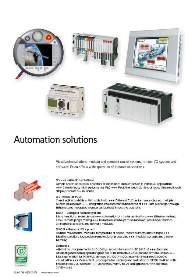
2010 CA08103002Z-EN www.eaton.com XV - visualisation solutions Simple operation relieves operators of machinery, installations or in individual applications +++ Simultaneous high performance PLC +++ Resistive touch displays or robust infrared touch displays from 3.5 – 15 inchesXC - modular PLCs Construction scalable within wide limits +++ Different PLC performance classes, multiple expansion modules +++ Integration into communication concept +++ Data exchange through Ethernet and integrated Web server facilitate innovative solutionsEC4P – Compact control system Many functions in one device +++ Automation of smaller applications +++ Ethernet variants allow remote programming +++ Numerous local expansion modules, eayNet extensions, CANopen extensions and network modulesXI/ON – Remote I/O system Control movements, measure temperature or speed, record currents and voltages +++ Ideal for solutions focused on remote signal processing +++ Modular concept and simple handlingSoftware All controls programmed with CoDeSys in compliance with IEC 61131-3 +++ Easy and efficient generation of operator guidance with interactive visualization software Galileo +++ Mask generation for HMI-PLC devices (XV100, XV400); also with integrated CoDeSys visualization +++ Convenient, uncomplicated planning and realization of XI/ON stations with the cost-free I/O Assistant +++ Generate SmartWire-DT configurations with cost-free SWD-Assist Visualization solutions, modular and compact control systems, remote I/O systems and software: Eaton offer a wide spectrum of automation solutions. Automation solutions
System overview Touch Panel XV 14/2 Description Touch Panel XV 14/4 Ordering Touch Panel XV HMI(-PLC) XV100 14/5 HMI-PLC XV200 14/6 HMI-PLC MFD4, HMI XVH300 14/7 HMI-PLC XVS400 14/8 HMI Mobile Panel XVM400 14/9 HMI-PLC XV400 14/10 XV accessories 14/12 Engineering Communication protocols, licensing 14/14 Technical data Touch Panel XV HMI(-PLC) XV100 14/18 HMI-PLC XV200 14/20 HMI-PLC MFD4 14/22 HMI Mobile Panel 14/23 HMI XVH300 14/24 HMI-PLC XV400 14/28 HMI-PLC XVS400 14/32 Dimensions Touch Panel XV 14/34 System overview XC100, XC121, XC200 modular PLCs 14/36 Ordering XC100, XC121, XC200 modular PLCs 14/38 XI/OC input/output expansion 14/39 Accessories 14/40 Technical data XC100 modular PLCs 14/42 Text display for XC100 modular PLC 14/44 XC121 modular PLCs 14/45 Input/output expansion for XC121 14/47 XC200 modular PLCs 14/49 I/O expansions XI/OC 14/51 Dimensions XC100, XC200 Modular PLCs 14/59 XI/OC input/output expansion 14/59 Text display for XC100 modular PLC 14/60 XC121 modular PLCs, XIO-EXT expansion 14/60 System overview EC4P compact PLCs 14/62 Ordering EC4P compact PLCs 14/64 Expansion devices 14/65 Accessories 14/66 Technical data EC4P compact PLCs 14/70 I/O expansions EC4E 14/75 MFD-CP4-CO communication modules 14/79 Dimensions Compact PLCs, I/O expansions, 14/80 communication modules System overview Remote I/O XI/ON 14/82 Description Remote I/O XI/ON 14/84 Selection chart 14/85 Maximum system configuration 14/86 Ordering Gateways 14/88 Power supply modules 14/90 I/O modules 14/91 Technology modules 14/93 Basic modules 14/94 I/O expansions, SWD, accessories 14/97 Engineering Gateways, supply modules 14/99 I/O modules 14/100 Technology modules 14/110 Technical data General information, terminals 14/111 Gateways 14/112 Supply modules 14/113 I/O modules 14/114 Technology Modules 14/122 Dimensions Gateways, XNE electronics modules 14/124 XN Electronics modules 14/125 Base modules 14/126 Software 14/128 Power supplies 14/131 Automation products
14/2 Automation products 2010 CA08103002Z-EN www.eaton.com Visualization Visualization System overview 4 4 6 10 8 11 6 1 2 5 1 7 5 9 3 180 180
2010 CA08103002Z-EN www.eaton.com Automation products Visualization 14/3 XV100 HMI/PLC with touch display 1 Compact operator panels with wide range of functions.Fully-graphical 3.5”, 5.7” or 7” wide-screen devices.TFT display, color or monochromeResistive touchEthernet interface on board.In addition CAN, PROFIBUS, RS232 or RS485 possible.→ Page 14/5 SD memory card 2 Optional memory for project, recipe data, etc.→ Page 14/12 XV license product certificate 3 Expansion of device functionality through assignment of license points.Licensing is through the Internet.→ Page 14/12 XV200 HMI/PLC with touch display 4 Fully graphic 5.7” devices with monochrome or color display (STN).Resistive touchEthernet interface on board.In addition CAN, PROFIBUS, or RS232 possible.→ Page 14/6 Compact-Flash memory card 5 Memory for project, recipe data, etc.With or without pre-installed Win CE operating system.→ Page 14/12 XV400 HMI/PLC with touch display 6 5.7”, 8.4”, 10.4”, 12.1”, 15” devicesTFT color displayInfra-red or Resistive-touch.Numerous communication possibilities through pluggable communication cards.Also available in stainless steel design.→ Page 14/10 XV license product certificate 7 Expansion of device functionality through assignment of license points.Licensing is through the Internet.→ Page 14/12 Windows CE licence 8 Win CE license with license label.→ Page 14/12 Communication card for XV400 9 Depending on device size 1 or 2 cards can be plugged in.→ Page 14/13 Mounting kit 10 Additional fixing kits for all XV devices.Fixing kit are generally included as standard.The illustration shows an XV-100 fixing kit.→ Page 14/12 Software 11 Visualization software Galileo Programming software XSOFT-CODESYS, EPAM→ Page 14/130
2010 CA08103002Z-EN www.eaton.com 14/4 Automation products Visualization Visualization Description HMI with integratable PLC The modern touch displays XV can optionally be used as fully-featured PLCs. This cost-saving, leading-edge concept offers the perfect solution for every application, whether in the low-cost segment or in the demanding high-end segment, where perfor-mance is key. The devices are available in display sizes from 3.5” to 15” and, depending on model with resistive or infrared touch. Alter-natively, the panels can also be mounted edgewise. XV100: Designed for the low-cost segment, these devices excel with a compact design, light-weight plastic housing and a wide range of onboard interfaces. Despite its small size, the XV100 with 3.5” touch display has an exceptional range of performance features, including PLC function. The touch panels with 5.7” and 7” display feature an additional USB host and an RS232 interface. XVS400 and XV400: These multipur-pose devices with their rugged metal housing are exceptionally flexible and provide comprehensive communica-tion possibilities. The XVS400 features a PROFIBUS-DP master/MPI interface as standard as well as Ethernet, RS232 and onboard USB host. With optional communication modules the XV400 can be easily and quickly expanded and adapted. The XV400 with stainless steel front is also ideally equipped for special applications:• IP69K: cleaning using high-pressure and steam jets (5.7“) • Ex zone 1: For use in potentially explosive atmospheres (10.4” and 12.1”) XVM400: The mobile version with its round, ergonomic design is easy to operate with just one hand. Licencing procedure To make sure that you pay for only those functions that you actually need, the devices work with a license point system. Use the points to activate specific functions, such as:• Runtime for the visualization (GALILEO or EPAM) • Communication (e.g. Ethernet, CANopen, Siemens MPI) • Tools (e.g. CE Telediag, S7 PG Router) • XSOFT-CODESYS-2 runtime for the PLC function With license product certificates you can buy additional license points. This has the following benefits for you:• Cost optimization• Low warehousing costs• Flexible handling → For detailed information about this topic see chapter Licensing
Automation products HMI(-PLC) XV100 2010 CA08103002Z-EN www.eaton.com Visualization 14/5 VisualizationHMI(-PLC) XV100 Ordering Display Front design Screen diagonal Resolution Communication interface Part No.Article No. PriceSee price list Std. pack Inches Pixels XV100 • HMI or HMI PLC with communication through on-board interface.• Communication scope extendable through licensing, → Page 14/12.• Standard front, special front please inquire• Insulating enclosure and front plate• Processor: RISC central processing unit, 32-bit, 400 MHz• OS, program and data memory: 64 MB• 1 slot for 1 SD card• Software (engineering): Visualization = GALILEO or EPAM, PLC = XSOFT-CODESYS-2 (depending on version) • Windows CE Core 5.0 license (incl.)– Built-in interfaces: 1 × Ethernet 100/10, 1 × USB device, communications interface– No PLC function possible Resistive touch3.5'' TFT LCD32 grey levels Standard membrane (fully enclosed) 3.5 320 x 240 – XV-102-A0-35MQR-10141759 1 off 3.5 320 x 240 PROFIBUS XV-102-A2-35MQR-10141820 3.5 320 x 240 RS232 XV-102-A3-35MQR-10141821 3.5 320 x 240 RS485 XV-102-A4-35MQR-10141822 3.5 320 x 240 CANRS232 XV-102-A5-35MQR-10141823 – Built-in interfaces: 1 × Ethernet 100/10, 1 × USB device, communications interface– Can be expanded with PLC function, → Page 14/14 Resistive touch3.5'' TFT LCD64 k Colors Standard membrane (fully enclosed) 3.5 320 x 240 – XV-102-B0-35TQR-10140007 1 off 3.5 320 x 240 PROFIBUS XV-102-B2-35TQR-10140008 3.5 320 x 240 RS232 XV-102-B3-35TQR-10140009 3.5 320 x 240 RS485 XV-102-B4-35TQR-10140010 3.5 320 x 240 CANRS232 XV-102-B5-35TQR-10140011 – Including PLC function– Built-in interfaces: 1 × Ethernet 100/10, 1 × USB device, communications interface Resistive touch3.5'' TFT LCD32 grey levels Standard membrane (fully enclosed) 3.5 320 x 240 – XV-102-B0-35MQR-10-PLC140012 1 off 3.5 320 x 240 RS232 XV-102-B3-35MQR-10-PLC140013 3.5 320 x 240 RS485 XV-102-B4-35MQR-10-PLC140014 3.5 320 x 240 CANRS232 XV-102-B5-35MQR-10-PLC140015 3.5 320 x 240 CANRS485 XV-102-B6-35MQR-10-PLC140016 3.5 320 x 240 PROFIBUSRS485 XV-102-B8-35MQR-10-PLC140017 Resistive touch3.5'' TFT LCD64 k Colors 3.5 320 x 240 – XV-102-B0-35TQR-10-PLC140018 3.5 320 x 240 RS232 XV-102-B3-35TQR-10-PLC140019 3.5 320 x 240 RS485 XV-102-B4-35TQR-10-PLC140020 3.5 320 x 240 CANRS232 XV-102-B5-35TQR-10-PLC140021 3.5 320 x 240 CANRS485 XV-102-B6-35TQR-10-PLC140022 3.5 320 x 240 PROFIBUSRS485 XV-102-B8-35TQR-10-PLC140023 Information relevant for export to North America Product Standards UL 60950-01; cUL; IEC/EN 61131-2; CE marking UL File No. E208621 UL CCN NWGQ2, NWGQ8 CSA File No. UL report applies to both US and Canada CSA Class No. - NA Certification UL Recognized, certified by UL for use in Canada Conditions of Acceptability The investigated Pollution Degree is: 2The following end-product enclosures are required: Fire. The unit must be supplied via a SELV source. The provided Ethernet Connection is only allowed to connect to inhouse networks Degree of Protection IEC: IP65, UL/CSA Type: - HPL14005EN
14/6 Automation products HMI(-PLC) XV100, HMI-PLC XV200 2010 CA08103002Z-EN www.eaton.com Visualization VisualizationHMI(-PLC) XV100, HMI-PLC XV200 Display Front design Screen diagonal Resolution Communication interface Part No.Article No. PriceSee price list Std. pack Inches Pixels XV100 – Built-in interfaces: 1 × Ethernet 100/10, 1 × USB device, 1 × USB host, communications interface– Can be expanded with PLC function, → Page 14/14 Resistive touch5.7" TFT LCD64 k Colors Standard membrane (fully enclosed) 5.7 640 x 480 RS232 XV-102-D0-57TVR-10142530 1 off 5.7 640 x 480 CANRS232RS485 XV-102-D6-57TVR-10142531 5.7 640 x 480 PROFIBUSRS232RS485 XV-102-D8-57TVR-10142532 Resistive touch7" TFT LCD64 k Colors 7 800 x 480 RS232 XV-102-D0-70TWR-10142535 7 800 x 480 CANRS232RS485 XV-102-D6-70TWR-10142536 7 800 x 480 PROFIBUSRS232RS485 XV-102-D8-70TWR-10142537 – Including PLC function– Built-in interfaces: 1 × Ethernet 100/10, 1 × USB device, 1 × USB host, communications interface Resistive touch5.7" TFT LCD64 k Colors Standard membrane (fully enclosed) 5.7 640 x 480 CANRS232RS485 XV-102-D6-57TVR-10-PLC142533 1 off 5.7 640 x 480 PROFIBUSRS232RS485 XV-102-D8-57TVR-10-PLC142534 Resistive touch7" TFT LCD64 k Colors 7 800 x 480 CANRS232RS485 XV-102-D6-70TWR-10-PLC142538 7 800 x 480 PROFIBUSRS232RS485 XV-102-D8-70TWR-10-PLC142539 Display Front design Screen diagonal Resolution Communication interface Part No.Article No. PriceSee price list Std. pack Inches Pixels XV200 • HMI or HMI PLC with communication through on-board interface.• PLC function and communications scope can be upgraded with licenses, → Page 14/12.• Standard front, special front please inquire• Insulating enclosure and front plate• Processor: RISC central processing unit, 32-bit, 200 MHz • OS, program and data memory: 32 MB.• Built-in interfaces: 1 × Ethernet, 1 × USB device, communications interface• 1 slot for 1 Compact Flash™ card.• Software (engineering): visualization = GALILEO or EPAM, PLC = XSOFT-CODESYS-2• Windows CE license required• Compact Flash™ required → XV accessories• Flush mounting compatible with 5.7” XV-400 devices and older predecessors Resistive touch5.7" FSTN LCD (monochrome display)256 grey levels Standard membrane 5.7 320 x 240 CAN XV-230-57CNN-1-10139951 1 off 5.7 320 x 240 PROFIBUS XV-230-57MPN-1-10139952 5.7 320 x 240 RS232 XV-232-57BAS-1-10139950 Resistive touch5.7" CSTN LCD(Color display) 5.7 320 x 240 CANRS232 XV-252-57CNN-1-10139956 5.7 320 x 240 PROFIBUSRS232 XV-252-57MPN-1-10139957 Information relevant for export to North America Product Standards UL 60950-01; cUL; IEC/EN 61131-2; CE marking UL File No. E208621 UL CCN NWGQ2, NWGQ8 CSA File No. UL report applies to both US and Canada CSA Class No. – NA Certification UL Recognized, certified by UL for use in Canada Conditions of Acceptability The investigated Pollution Degree is: 2 The following end-product enclosures are required: Fire, ElectricalThe unit must be supplied via a SELV source.The provided Ethernet Connection is only allowed to connect to inhouse networks. Degree of Protection IEC: IP65, UL/CSA Type: - HPL14006EN
Automation products HMI-PLC MFD4, HMI XVH300 2010 CA08103002Z-EN www.eaton.com Visualization 14/7 VisualizationHMI-PLC MFD4, HMI XVH300Visualization Visualization Display Screen diagonal Resolution Communication interface Part No.Article No. PriceSee price list Std. pack Inches Pixels MFD4 • Memory card pluggable (optional) → Page 14/41• Real-time clock• Operating system: Windows CE Resistive touch5.7" TFT LCD32 k Colors 5.7 320 x 240 EthernetCANopen/easyNetRS232 MFD4-5-XRC-30109428 1 off XVH300 • HMI (No PLC function possible) with communication through on-board interface.• Communication scope extendable through licensing, → Page 14/12.• Standard front, special front please inquire• Metal enclosure and front plate• Processor: RISC central processing unit, 32-bit, 200 MHz • OS, program and data memory: 64 MB• Display: 5.7" CSTN LCD (Color display), 256 colors• Built-in interfaces: 1 × Ethernet, 1 × USB device, communications interface• 1 slot for 1 Compact Flash™ card• Software (engineering): visualization = GALILEO or EPAM• WinCE license required → XV accessories• Compact Flash™ required → XV accessories Infra-red touch5.7" CSTN LCD (Color display) Standard front with standard membraneLaminated safety glass, non-reflective 5.7 320 x 240 – XVH-340-57BAS-1-10139869 1 off 5.7 320 x 240 CAN XVH-340-57CAN-1-10139870 5.7 320 x 240 PROFIBUS XVH-340-57MPI-1-10139871 5.7 320 x 240 RS485 (Suconet K)RS232 (Sucom A) XVH-342-57SKS-1-10139873 Satin-finish brushed stainless steelLaminated safety glass, non-reflective 5.7 320 x 240 CAN XVH-340-57CAN-1-50 1) 139872 Resistive touch5.7" CSTN LCD (Color display) Standard front with standard membrane (fully laminated) 5.7 320 x 240 – XVH-330-57BAS-1-10139866 5.7 320 x 240 CAN XVH-330-57CAN-1-10139867 5.7 320 x 240 PROFIBUS XVH-330-57MPI-1-10139868 Notes 1) Approved for IP69K. Observe installation instructions to IP69K. Information relevant for export to North America Product Standards UL 60950-01; cUL; IEC/EN 61131-2; CE marking UL File No. E208621 UL CCN NWGQ2, NWGQ8 CSA File No. UL report applies to both US and Canada CSA Class No. – NA Certification UL Recognized, certified by UL for use in Canada Conditions of Acceptability The investigated Pollution Degree is: 2Proper bonding to the end-product main protective earthing termination is: RequiredThe following end-product enclosures are required: Fire, ElectricalThe unit must be supplied via a SELV source.The provided Ethernet Connection is only allowed to connect to inhouse networks. Degree of Protection IEC: IP65, UL/CSA Type: - HPL14007EN
14/8 Automation products HMI-PLC XVS400 2010 CA08103002Z-EN www.eaton.com Visualization Visualization VisualizationHMI-PLC XVS400 Display Front design Screen diagonal Resolution Part No.Article No. PriceSee price list Std. pack Inches Pixels XVS400 • HMI or HMI PLC with communication through on-board interface.• PLC function and communications scope can be upgraded with licenses, → Page 14/12.• Standard front, special front please inquire• Metal enclosure and front plate• Processor: RISC central processing unit, 32-bit, 400 MHz• OS, program and data memory: 64 MB• Software (engineering): visualization = GALILEO or EPAM, PLC = XSOFT-CODESYS-2• WinCE license required → XV accessories• Compact Flash™ required → XV accessories – Display: 5.7" CSTN LCD (color display), 256 colors – 1 slot for Compact Flash™ cards – Built-in interfaces: 1 × Ethernet 100/10, 1 × RS232, 1 × PROFIBUS, 1 × USB host, 1 × USB device Resistive touch5.7" CSTN LCD (Color display) Standard membrane (fully laminated) 5.7 320 x 240 XVS-430-57MPI-1-10139967 1 off Infra-red touch5.7" TFT LCD Standard membraneLaminated safety glass, non-reflective 5.7 320 x 240 XVS-460-57MPI-1-10139970 – Display: 5.7" or 8.4" TFT LCD (Color display), adjustable: 65536 or 256 colors – 1 slot for Compact Flash™ card – Built-in interfaces: 1 × Ethernet 100/10, 1 × RS232, 1 × PROFIBUS, 1 × USB host, 1 × USB device Infra-red touch5.7" CSTN LCD (Color display) Standard membraneLaminated safety glass, non-reflective 5.7 320 x 240 XVS-440-57MPI-1-10139968 1 off Resistive touch5.7" TFT LCD Standard membrane (fully laminated) 5.7 320 x 240 XVS-450-57MPI-1-10139969 Infra-red touch8.4" TFT LCD Standard membraneLaminated safety glass, non-reflective 8.4 640 x 480 XVS-460-84MPI-1-10139971 – Display: 10.4", 12.1" or 15" TFT LCD (Color display), adjustable: 65536 or 256 colors – 2 slots for Compact Flash™ cards – Built-in interfaces: 1 × Ethernet 100/10, 1 × RS232, 1 × PROFIBUS, 2 × USB host, 1 × USB device Infra-red touch10.4" TFT LCD Standard membraneLaminated safety glass, non-reflective 10.4 640 x 480 XVS-440-10MPI-1-10139973 1 off Resistive touch10.4" TFT LCD Standard membrane (fully laminated) 10.4 640 x 480 XVS-430-10MPI-1-10139972 Infra-red touch12.1" TFT LCD Standard membraneLaminated safety glass, non-reflective 12.1 800 x 600 XVS-440-12MPI-1-10139975 Resistive touch12.1" TFT LCD Standard membrane (fully laminated) 12.1 800 x 600 XVS-430-12MPI-1-10139974 Infra-red touch15" TFT LCD Standard membraneLaminated safety glass, non-reflective 15 1024 x 768 XVS-460-15MPI-1-10139976 Information relevant for export to North America Product Standards UL 60950-01; cUL; IEC/EN 61131-2; CE marking UL File No. E208621 UL CCN NWGQ2, NWGQ8 CSA File No. UL report applies to both US and Canada CSA Class No. – NA Certification UL Recognized, certified by UL for use in Canada Conditions of Acceptability The investigated Pollution Degree is: 2Proper bonding to the end-product main protective earthing termination is: RequiredThe following end-product enclosures are required: Fire, ElectricalThe unit must be supplied via a SELV source.The provided Ethernet Connection is only allowed to connect to inhouse net-works. Degree of Protection IEC: IP65, UL/CSA Type: - HPL14008EN
Automation products HMI Mobile Panel 2010 CA08103002Z-EN www.eaton.com Visualization 14/9 VisualizationHMI Mobile Panel Display Operating elements Part No.Article No. PriceSee price list Std. pack Information relevant for export to North America XVM400 • Mobile HMI (No PLC function possible) with communication through on-board interface. • Communication scope extendable through licensing, → Page 14/12. • Standard front, 31 membrane keys, 4 status LEDs• Insulating enclosure and front plate• Processor: RISC central processing unit, 32-bit, 400 MHz• OS, program and data memory : min 64 MB• Built-in interfaces: 1 × Ethernet, 1 × RS232-C, 1 × USB host• Software (engineering): Visualization = GALILEO (runtime already installed) • Windows CE 5.0 license (incl.) Resistive touch6.5" TFT LCD64 k Colors 2 acknowledgement keys (3-stage, 2-circuit) externally wiredEmergency switching off button (2-circuit), externally wired XVM-430-65TVB-1-11139996 1 off Product Standards UL 508; cUL; IEC/EN 6113-2; CE marking UL File No. E176666 UL CCN NRAQ, NRAQ7 CSA File No. UL report applies to both US and Canada CSA Class No. - NA Certification UL Recognized, certified by UL for use in Canada Degree of Protection IEC: IP65, UL/CSA Type: - Resistive touch6.5" TFT LCD64 k Colors 2 acknowledgement keys (3-stage, 2-circuit) externally wiredEmergency switching off button (2-circuit), externally wiredKey switch (3-position), internally wiredElectronic hand wheel, internally wired XVM-450-65TVB-1-11139998 Resistive touch6.5" TFT LCD64 k Colors 2 acknowledgement keys (3-stage, 2-circuit) externally wiredKey switch (3-position), internally wiredElectronic hand wheel, internally wired XVM-410-65TVB-1-11139997 HPL14009EN
14/10 Automation products HMI-PLC XV400 2010 CA08103002Z-EN www.eaton.com Visualization VisualizationHMI-PLC XV400 Display Front design Screen diagonal Resolution Part No.Article No. PriceSee price list Std. pack Notes Inches Pixels XV400 • HMI or HMI PLC with communication through on-board interface.• PLC function and communications scope can be upgraded with licenses, → Page 14/12.• Standard front, stainless steel front, special fronts please inquire• Metal enclosure and front plate• Processor: RISC central processing unit, 32-bit, 400 MHz• OS, program and data memory: 64 MB• Software (engineering): visualization = GALILEO or EPAM, PLC = XSOFT-CODESYS-2• WinCE license required → XV accessories• Compact Flash™ required →S XV accessories – Display: 5.7" CSTN LCD (color display), 256 colors – 1 slot for Compact Flash™ cards – 1 slot for communication cards – Built-in interfaces: 1 × Ethernet 100/10, 1 × RS232, 1 × CAN, 1 × USB host, 1 × USB device Infra-red touch5.7" CSTN LCD (Color display) Standard front with standard membraneLaminated safety glass, non-reflective 5.7 320 x 240 XV-442-57CQB-1-10139892 1 off – Infra-red touch5.7" CSTN LCD (Color display) Four-hole front with standard membraneLaminated safety glass, non-reflective 5.7 320 x 240 XV-442-57CQB-1-20139894 1) Infra-red touch5.7" CSTN LCD (Color display) Satin-finish brushed stainless steelLaminated safety glass, non-reflective 5.7 320 x 240 XV-442-57CQB-1-50139896 1) 2) Resistive touch5.7" CSTN LCD (Color display) Standard front with standard membrane (fully laminated) 5.7 320 x 240 XV-432-57CQB-1-10139890 – – Display: 5.7" or 8.4" TFT LCD (Color display), adjustable: 65536 or 256 colors – 1 slot for Compact Flash™ card – 1 slot for communication cards – Built-in interfaces: 1 × Ethernet 100/10, 1 × RS232, 1 × CAN, 1 × USB host, 1 × USB device Infra-red touch5.7" TFT LCD Standard front with standard membraneLaminated safety glass, non-reflective 5.7 320 x 240 XV-460-57TQB-1-10139897 1 off – Infra-red touch5.7" TFT LCD Satin-finish brushed stainless steelLaminated safety glass, non-reflective 5.7 320 x 240 XV-460-57TQB-1-50139898 2) Resistive touch5.7" TFT LCD Standard front with standard membrane (fully laminated) 5.7 320 x 240 XV-450-57TQB-1-10139899 – Infra-red touch8.4" TFT LCD Standard front with standard membraneLaminated safety glass, non-reflective 8.4 640 x 480 XV-460-84TVB-1-10139900 – Instructions 1) Not for new applications. 2) Approved for II 2G Ex px II IP5x (ATEX 94/9/EC): Observe installation instructions to IP69K. Information relevant for export to North America Product Standards UL 60950-01; cUL; IEC/EN 61131-2; CE marking UL File No. E208621 UL CCN NWGQ2, NWGQ8 CSA File No. UL report applies to both US and Canada CSA Class No. – NA Certification UL Recognized, certified by UL for use in Canada Conditions of Acceptability The investigated Pollution Degree is: 2Proper bonding to the end-product main protective earthing termination is: RequiredThe following end-product enclosures are required: Fire, ElectricalThe unit must be supplied via a SELV source.The provided Ethernet Connection is only allowed to connect to inhouse networks. Degree of Protection IEC: IP65, UL/CSA Type: - HPL14010EN
Automation products HMI-PLC XV400 2010 CA08103002Z-EN www.eaton.com Visualization 14/11 XV400 – Display: 10.4", 12.1" or 15" TFT LCD (Color display), adjustable: 65536 or 256 colors – 2 slots for Compact Flash™ cards – 2 slots for communication cards – Built-in interfaces: 1 × Ethernet 100/10, 1 × RS232, 1 × CAN, 2 × USB host, 1 × USB device Infra-red touch10.4" TFT LCD Standard front with standard membraneLaminated safety glass, non-reflective 10.4 640 x 480 XV-440-10TVB-1-10139904 1 off – Infra-red touch10.4" TFT LCD Four-hole front with standard membraneLaminated safety glass, non-reflective 10.4 640 x 480 XV-440-10TVB-1-20139906 1 off 1) Infra-red touch10.4" TFT LCD Satin-finish brushed stainless steelLaminated safety glass, non-reflective 10.4 640 x 480 XV-440-10TVB-1-50139908 1 off 2) Resistive touch10.4" TFT LCD Standard front with standard membrane (fully laminated) 10.4 640 x 480 XV-430-10TVB-1-10139902 1 off – Infra-red touch12.1" TFT LCD Standard front with standard membraneLaminated safety glass, non-reflective 12.1 800 x 600 XV-440-12TSB-1-10139911 1 off – Infra-red touch12.1" TFT LCD Four-hole front with standard membraneLaminated safety glass, non-reflective 12.1 800 x 600 XV-440-12TSB-1-20139913 1 off 1) Infra-red touch12.1" TFT LCD Satin-finish brushed stainless steelLaminated safety glass, non-reflective 12.1 800 x 600 XV-440-12TSB-1-50139915 1 off 2) Resistive touch12.1" TFT LCD Standard front with standard membrane (fully laminated) 12.1 800 x 600 XV-430-12TSB-1-10139909 1 off – Infra-red touch15" TFT LCD Standard front with standard membraneLaminated safety glass, non-reflective 15 1024 x 768 XV-460-15TXB-1-10139916 1 off – Infra-red touch15" TFT LCD Four-hole front with standard membraneLaminated safety glass, non-reflective 15 1024 x 768 XV-460-15TXB-1-20139917 1 off 1) Infra-red touch15" TFT LCD Satin-finish brushed stainless steelLaminated safety glass, non-reflective 15 1024 x 768 XV-460-15TXB-1-50139918 1 off – Instructions 1) Not for new applications. 2) Approved for II 2G Ex px II IP5x (ATEX 94/9/EC): Zone 1, Category 2G (Only for flush-mounting in a pressurized enclosure! Max. permissible excess pressure: 10 mbar continuous.) Zone 2, Category 3G (Only for flush-mounting in a pressurized enclosure! Max. permissible excess pressure: 10 mbar continuous.) Information relevant for export to North America Product Standards UL 60950-01; cUL; IEC/EN 61131-2; CE marking UL File No. E208621 UL CCN NWGQ2, NWGQ8 CSA File No. UL report applies to both US and Canada CSA Class No. – NA Certification UL Recognized, certified by UL for use in Canada Conditions of Acceptability The investigated Pollution Degree is: 2Proper bonding to the end-product main protective earthing termination is: RequiredThe following end-product enclosures are required: Fire, ElectricalThe unit must be supplied via a SELV source.The provided Ethernet Connection is only allowed to connect to inhouse networks. Degree of Protection IEC: IP65, UL/CSA Type: - Display Front design Screen diagonal Resolution Part No.Article No. PriceSee price list Std. pack Notes Inches Pixels HPL14011EN
14/12 Automation products XV accessories 2010 CA08103002Z-EN www.eaton.com Visualization VisualizationXV accessories Description For use with Part No.Article No. PriceSee price list Std. pack Information relevant for export to North America Windows CE licenses License for Windows CE 3.0 incl. license label XV-2…XVH-3…XV-4…XVS-4… LIC-OS-CE30140405 1 off UL/CSA certification not required License for Windows CE 5.0 Core incl. license label LIC-OS-CE50-C140406 License for Windows CE 5.0 Professional Plus incl. license label LIC-OS-CE50-PP140408 Memory cards SD memory card with min. 128 MByteWithout operating system XV-1… MEMORY-SD-A1-S139807 1 off UL/CSA certification not required Compact flash with min. 128 MByteWithout operating system XV-2…XVH-3…XV-4…XVS-4… MEMORY-CF-A1-S139528 Compact flash with min. 128 MByteWindows CE 3.0 preinstalledWithout Windows license (license required (LIC-OS-CE30)) XV-2…XVH-3…XV-4…XVS-4… OS-FLASH-A1-S140366 Compact flash with min. 128 MByteWindows CE 5.0 Core preinstalledWithout Windows license (license required (LIC-OS-CE 50-C)) OS-FLASH-A1-C140368 XV license product certificates License product certificate PLC with license labelCOMPACT XV-1…-B…XV-1…-D… LIC-PLC-MXP-COMPACT142581 1 off UL/CSA certification not required License product certificate PLC with license labelLIGHT XV-2…-57BAS…XV-2…-57CNN… LIC-PLC-MXP-LIGHT140388 License product certificate PLC with license label SMALL XV-2…-57MPN…XV-4…-57…XV-4…-84…XVS-4…-57…XVS-4…-84… LIC-PLC-MXP-SMALL140389 License product certificate PLC with license label MEDIUM XV-4…-10…XV-4…-12…XV-4…-15…XVS-4…-10…XVS-4…-12…XVS-4…-15… LIC-PLC-MXP-MEDIUM140390 License product certificate 40 POINTS XV-1…XV-2…XVH-3…XV-4…XVS-4…XVM-4... LIC-OPT-1ST-LEVEL140391 License product certificate 80 POINTS LIC-OPT-2ND-LEVEL140392 License product certificate 160 POINTS LIC-OPT-3RD-LEVEL140393 Additional fixing brackets 4 mounting brackets with grub screw XVH-3…XV-4…XVS-4… ACCESSORIES-HKS-IP65139809 1 off UL/CSA certification not required 100 mounting brackets with grub screw ACCESSORIES-HKS-IP65-100139810 HPL14012EN
Automation products XV accessories 2010 CA08103002Z-EN www.eaton.com Visualization 14/13 Standard accessories Supplied as standard with devices Device accessories as replacement for insulated devices:8 mounting brackets with grub screw for flush mounting1 sealing profile for flush mounting device1 power supply plug1 touch pen XV-1…XV-2… ACCESSORIES-TP-57-KG-1139837 1 off UL/CSA certification not required Device accessories as replacement for 5.7” devices with resistive touch and metal front:4 mounting brackets with grub screw for flush mounting1 sealing profile for flush mounting device1 power supply plug1 touch pen XVH-330…XV-432-57…XV-450-57…XVS-430-57…XVS-450-57… ACCESSORIES-TP-57-RES-1139827 Device accessories as replacement for 5.7” devices with infrared touch and standard front:4 mounting brackets with grub screw for flush mounting1 sealing profile for flush mounting device1 power supply plug XVH-34…XV-442-57…XV-460-57…XVS-440-57…XVS-460-57… ACCESSORIES-TP-57-IR-1 1) 139828 Device accessories as replacement for 5.7” devices with infrared touch and stainless steel front:8 mounting brackets with grub screw for flush mounting1 seal for flush mounting device1 power supply plug XVH-340-57…-50XV-442-57…-50XV-460-57…-50 ACCESSORIES-TP-57-EST-1139830 Device accessories as replacement for 10.4” and 12.1” devices with resistive touch:6 mounting brackets with grub screw for flush mounting1 sealing profile for flush mounting device1 power supply plug1 touch pen XV-430-10…XV-430-12…XVS-430-10…XVS-430-12… ACCESSORIES-TP-10/12-RES-1139831 UL/CSA certification not required Device accessories as replacement for 10.4”, 12.1” and 15” devices with infrared touch:8 mounting brackets with grub screw for flush mounting1 sealing profile for flush mounting device1 power supply plug XV-440-10…XV-440-12…XV-440-15…XVS-440-10…XVS-440-12…XVS-460-15…XP-7…-10…XP-7…-12…XP-7…-15… ACCESSORIES-TP-15-IR-1139843 Communication cardsProtocols for communication cards→ Page 14/14 Multiple protocol card XV-4… COM-MPB1-TP139850 1 off UL/CSA certification refer to main component information Multiple protocol card MPI COM-MPB2-TP139847 PROFIBUS-DP master (12 MBaud) COM-DPM-MC2139853 PROFIBUS-DP slave (12 MBaud) COM-PDP-TP139849 EIB (3rd release) COM-EIB2-TP139852 Accessories for Mobile Panel Wall mount with cable holder XVM-4… KETOP-WB095139999 1 off UL/CSA certification not required Switch box outside control panel IP65 KETOP-CB211140002 1 off – Switch box for installation inside control panel JB001/ASET140003 1 off – Connection cable, 5 m KETOP-TT050-MV1140000 1 off UL/CSA certification not required Connection cable, 10 m KETOP-TT100-MV1140001 Connection cable, 15 m KETOP-TT150-MV1140005 Jumper plug for emergency switching off KETOP-BC001140004 Spare keys, 2 off XVM-410…XVM-450… KETOP-EKY001140006 Notes 1) XVH-340-57CAN-1-50, XV-442-57CQB-1-50 and XV-460-57TQB-1-50 have a special seal. Description For use with Part No.Article No. PriceSee price list Std. pack Information relevant for export to North America HPL14013EN
14/14 Automation products HMI, HMI-PLC 2010 CA08103002Z-EN www.eaton.com Visualization VisualizationHMI, HMI-PLC Engineering Protocols for communication cards for panel XV400 For panels XV400, communications protocols are available through optional plug-in communication cards (No license products required):Excerpt From the most common protocols, which are available for XV400 devices through optional plug-in communication cards: Protocol Required communication cards for XV400 EIB (3rd release) COM-EIB2-TP Matsushita FP series COM-MPB1-TP / COM-MPB2-TP Mitsubishi A series/F series COM-MPB1-TP / COM-MPB2-TP Moeller Suconet K COM-MPB1-TP / COM-MPB2-TP Omron C, H, or K series COM-MPB1-TP / COM-MPB2-TP PROFIBUS-DP master (12 Mbaud) COM-DPM-MC2 PROFIBUS-DP slave (12 Mbaud) COM-PDP-TP Siemens MPI COM-MPB2-TP Telemecanique Unitelway new COM-MPB1-TP / COM-MPB2-TP To inquire about further protocols, contact your vendor. Licensing for Panel XV… The panels XV100, XV200, XVH300, XV400, XVS400 and XVM400 are supplied with license points saved to the device. License points are required to be able to perform certain functions with the device:• XSOFT-CODESYS-2 runtime for the PLC function (not possible with XV-102-A…,XVH300 and XVM400)• Runtime for the visualization (GALILEO or EPAM)• Tools (e. g. CE Telediag, S7 PG Router)• Communication (e.g. Ethernet, CANopen, Siemens MPI) Number of license points supplied with standard devices:• 140 license points: XV100 (without PLC function), XV200, XVH300, XV400, XVS400• 240 license points: XV100 with PLC function• 260 licence points: XVM400 If the device does not contain enough license points for the required functions or to add the PLC function to the HMI, you must purchase additional license points. To do this you need one or more license product certificates. The following are available: • License product certificates for the PLC function: To enable the PLC function (XSOFT-CODESYS-2) special license product certificates are required. These contain a license label for the device type, which must be applied to the device fir legal reasons. • License product certificates for visualization, communication and tools Determining required license points For the visualization and tools and communication features used, add the license points required for each function. Communication connections to several devices with the same protocol must be counted only once. From this total, subtract the points already contained on the devices (e.g. 140 points). The difference is the number of license points that you must install for communication protocols and tools through license product certificates. Table: Required license points for runtime and tools Visualization/Tools Required on-board interface Licence points GALILEO-Runtime None 100 EPAM runtime None 100 XSOFT-CODESYS-2 runtime (PLC function) None 100 XSOFT-CODESYS-2 runtime (PLC function and TargetVisu function) None 200 CE Telediag RS232 40 S7 PG Router Ethernet and PROFIBUS 80 CAN Monitor CAN 0 Domain Server Ethernet 80
Automation products 2010 CA08103002Z-EN www.eaton.com Visualization 14/15 Visualization Communication cards for MICRO PANEL XV400 For panels XV400 further communications protocols are available through optional plug-in communication cards (No license products required). Depending on the required functionality the following license product certificates are available ( → XV accessories): Licensing examples Table: Required license points for communication through on-board interface Manufacturer PLC Protocol Required on-board interface Licence points XSOFT-CODE-SYS-2 Licence points GALILEO Licence points EPAM Eaton XV with PLC function Local - 0 0 XV with PLC function Ethernet 0 40 0 CANopen, master CAN 0 - - CANopen, PDO CAN 0 40 - CANopen, SDO CAN 0 40 - XV200 DP master (1.5 MBaud) PROFIBUS 40 - - XV100/XVS400 DP master (1.5 Mbaud) PROFIBUS 0 - - Modbus RTU RS232 0 40 - Modbus TCP Ethernet 0 80 - CoDeSys Ethernet 0 40 0 A. Bradley Logix DF1 RS232 - 120 - Logix Ethernet/IP Ethernet - 120 - MicroLogix SLC5/03 MicroLogix DF1 RS232 - 40 - Beckhoff TwinCAT ADS Ethernet - 80 - BC9000 ADS Ethernet - 80 - HIMA HIMatrix Modbus TCP Ethernet - 80 - Mitsubishi PG-AX/PG-FX RS232 - 40 - Eaton easy500/easy700 RS232 - 40 - easy800/MFD-Titan RS232 - 40 - PS4 RS232 - 40 - XC100, XC200 CAN - 40 - XC100, XC200 Ethernet - 40 - PS4 Suconet K (to XVH342-57SKS) Suconet K - 0 - Siemens S7 Industrial Ethernet Ethernet - 80 - S7 MPI PROFIBUS - 40 - S7 PROFIBUS-DP (1.5 Mbaud)S7 default profile PROFIBUS - 40 - S7-200 PPI PROFIBUS - 40 - - - XVM400 keypad Local - 40 - - Communication currently not available To inquire about further protocols, contact your vendor. HMI application: XV100, XV200, XVS400 Visualization, communicationVisualization (GALILEO) 100 Points Communication MPI 40 Points Communication CoDeSys external 40 Points Total 180 Points Contained in device on delivery -140 Points Additionally required points for communication 40 Points PLCPLC application No Required license product certificates:1 x LIC-OPT-1ST-LEVEL (40 points) Ethernet CoDeSys HMI MPI
14/16 Automation products 2010 CA08103002Z-EN www.eaton.com Visualization HMI application: XV100, XV200, XVS400, with additional software S7 PG Router Visualization, communicationVisualization (GALILEO) 100 Points Communication MPI 40 Points S7 PG Router 80 Points Total 220 Points Contained in device on delivery -140 Points Additionally required points for communication 80 Points PLCPLC application No Required license product certificates:1 x LIC-OPT-2ND-LEVEL (80 points) HMI-PLC Application: XV100 Visualization, communicationVisualization (GALILEO) 100 Points Communication HMI-PLC local 0 Points Communication CANopen or PROFIBUS-DP master (XSOFT-CODESYS-2) 0 Points Total 100 Points Contained in device on delivery -140 Points Additionally required points for communication 0 Points PLCPLC application 100 Points Required license product certificates:1 x LIC-PLC-MXP-COMPACT (100 points) For device versions XV-102-…-PLC license LIC-PLC-MXP-COMPACT is included with the device as standard (the device therefore has 240 license points). MPI Ethernet HMI + S7 PG Router Profibus DP HMI-PLC
Automation products 2010 CA08103002Z-EN www.eaton.com Visualization 14/17 Redeeming a license product certificate (XV100, XV200, XV400, XVS400, XVH300) 1 Order the required license product certificate. 2 Keep the following information available: – Certificate number of license product certificate– The serial number of your device– Your e-mail address 3 On the Micro Innovation website (www.microinnovation.com/license), select menu item “Validate License” and click [Start Licensing]. 4 In the new window that opens, enter your certificate number. The license product certificate is associated with a specific device through its serial number. The website generates a license code, which is immediately shown on the web page. 5 Enter the license code in your device: – On the device, select [Start] [Programs] [Control Panel].– Double-click the Licence icon.– Enter the license code with the License Administrator tool (Change Licence). 6 Restart the device. After the device has been restarted the new license points are available. Redeeming a license product certificate for XVM400 devices Follow the procedure described in document M002379 (Mobile PANEL XVM400), which you can find on the Micro Innovation website under “Downloads”. HMI-PLC Application: XV400 10.4“ Visualization, communicationVisualization (GALILEO) 100 Points Communication HMI-PLC local 0 Points Communication Modbus TCP client (GALILEO) 80 Points Communication CANopen (XSOFT-CODESYS-2) 0 Points Total 180 Points Contained in device on delivery -140 Points Additionally required points for communication 40 Points PLCPLC application 100 Points Required license product certificates:1 x LIC-OPT-1ST-LEVEL (40 points)1 x LIC-PLC-MXP-MEDIUM (100 points) For device versions XV-102-…-PLC license LIC-PLC-MXP-COMPACT is included with the device as standard (the device therefore has 240 license points). CAN Ethernet Modbus TCP HMI-PLC
14/18 Automation products HMI(-PLC) Visualization 2010 CA08103002Z-EN www.eaton.com 2010 CA08103002Z-EN www.eaton.com Automation products HMI(-PLC) Visualization VisualizationHMI(-PLC) XV-102-A...-35MQR-10 XV-102-B...-35MQR-10-PLC XV-102B...-35TQR-10 XV-102-B...-35TQR-10-PLC XV-102-D...-57TVR-10 XV-102-D...70TWR-10... Technical dataDisplay Screen diagonal/type 3.5" TFT LCD (monochrome) 3.5" TFT LCD (monochrome) 3.5" TFT LCD (color) 3.5" TFT LCD (color) 5.7" TFT LCD (color) 7" TFT LCD (color) Resolution QVGA (320 × 240 pixels or 240 × 320 pixels in portrait format) QVGA (320 × 240 pixels or 240 × 320 pixels in portrait format) QVGA (320 × 240 pixels or 240 × 320 pixels in portrait format) QVGA (320 × 240 pixels or 240 × 320 pixels in portrait format) VGA (640 × 480 pixels or 480 × 640 pixels in portrait format) WVGA (800 × 480 pixels or 480 × 800 pixels in portrait format) Visible screen area 70 mm x 53 mm 70 mm x 53 mm 70 mm x 53 mm 70 mm x 53 mm 115 mm x 86 mm 152 mm x 91 mm Color resolution (grayscale or color) 32 grey levels 32 grey levels 64 k Colors 64 k Colors 64 k Colors 64 k Colors Contrast ratio Normally 300:1 Normally 300:1 Normally 300:1 Normally 300:1 Normally 300:1 Normally 300:1 Brightness Normally 250 cd/m² Normally 250 cd/m² Normally 250 cd/m² Normally 250 cd/m² Normally 250 cd/m² Normally 250 cd/m² Backlight LED, dimmable via software LED, dimmable via software LED, dimmable via software LED, dimmable via software LED, dimmable via software LED, dimmable via software Lifespan of backlight Normally 40000 h Normally 40000 h Normally 40000 h Normally 40000 h Normally 40000 h Normally 40000 h Resistive touch protective screen Touch sensor (glass with membrane) Touch sensor (glass with membrane) Touch sensor (glass with membrane) Touch sensor (glass with membrane) Touch sensor (glass with membrane) Touch sensor (glass with membrane) OperationTechnology Resistive touch, 4-conductor Resistive touch, 4-conductor Resistive touch, 4-conductor Resistive touch, 4-conductor Resistive touch, 4-conductor Resistive touch, 4-conductor SystemProcessor RISC, 32 bit, 400 MHz RISC, 32 bit, 400 MHz RISC, 32 bit, 400 MHz RISC, 32 bit, 400 MHz RISC, 32 bit, 400 MHz RISC, 32 bit, 400 MHz Internal memory DRAM (OS, program and data memory) 64 MByte 64 MByte 64 MByte 64 MByte 64 MByte 64 MByte NAND FLASH (can be used for data backup) Approx. 128 Byte available Approx. 128 Byte available Approx. 128 Byte available Approx. 128 Byte available Approx. 128 Byte available Approx. 128 Byte available NVRAM (Retain data) – Approx. 32 kByte available Approx. 32 kByte available Approx. 32 kByte available Approx. 32 kByte available Approx. 32 kByte available External memory SD Memory Card Slot SDA Specification 1.00 SDA Specification 1.00 SDA Specification 1.00 SDA Specification 1.00 SDA Specification 1.00 SDA Specification 1.00 Real-time clock (battery backup) Battery Zero maintenance Zero maintenance Zero maintenance Zero maintenance Zero maintenance Zero maintenance Backup time at zero voltage Normally 10 years Normally 10 years Normally 10 years Normally 10 years Normally 10 years Normally 10 years Operating system Windows CE Windows CE Windows CE Windows CE Windows CE Windows CE EngineeringVisualization software GALILEO/EPAM GALILEO/EPAM GALILEO/EPAM GALILEO/EPAM GALILEO/EPAM GALILEO/EPAM PLC programming software – XSOFT-CODESYS-2 XSOFT-CODESYS-2 XSOFT-CODESYS-2 XSOFT-CODESYS-2 XSOFT-CODESYS-2 Interfaces, communicationEthernet 100Base-TX/10Base-T 100Base-TX/10Base-T 100Base-TX/10Base-T 100Base-TX/10Base-T 100Base-TX/10Base-T 100Base-TX/10Base-T USB Host – – – – USB 2.0 (1.5 - 12 Mbit/s), not isolated USB device USB 2.0, not isolated USB 2.0, not isolated USB 2.0, not isolated USB 2.0, not isolated USB 2.0, not isolated USB 2.0, not isolated Part No. ...A0… ...A2… ...A3… ...A4… ...A5… ...B0… ...B3… ...B4… ...B5… ...B6… ...B8… ...B0… ...B2… ...B3… ...B4… ...B5… ...B0… ...B3… ...B4… ...B5… ...B6… ...B8… ...D0… ...D6… ...D8… ...D6... PLC ...D8...PLC ...D0… ...D6… ...D8… ...D6... PLC ...D8...PLC System Port (RS232) – – ● 1) – ● 1) – ● 1) – ● 1) – – – – ● 1) – ● 1) – ● 1) – ● 1) – – ● 1) ● 1) ● 1) ● 1) ● 1) ● 1) ● 1) ● 1) ● 1) ● 1) CAN – – – – ● 2) – – – ● 2) ● 2) – – – – – ● 2) – – – ● 2) ● 2) – – ● 2) – ● 2) – – ● 2) – ● 2) – PROFIBUS – ● 3) – – – – – – – – ● 3) – ● 3) – – – – – – – – ● 3) – – ● 3) – ● 3) – – ● 3) – ● 3) RS485 – – – ● 4) – – – ● 4) – ● 4) ● 4) – – – ● 4) – – – ● 4) – ● 4) ● 4) – ● 4) ● 4) ● 4) ● 4) – ● 4) ● 4) ● 4) ● 4) Power supplyNominal voltage 24 V DC SELV (safety extra low voltage) 24 V DC SELV (safety extra low voltage) 24 V DC SELV (safety extra low voltage) 24 V DC SELV (safety extra low voltage) 24 V DC SELV (safety extra low voltage) 24 V DC SELV (safety extra low voltage) Permissible voltage R.m.s.: 19.2 – 30.0 V DC (rated operating voltage -20 %/+25 %)Absolute with ripple: 18.0 – 31.2 V DCBattery operation: 18.0 – 31.2 V DC (rated operating voltage -25 %/+30 %)35 V DC for a duration of 100 ms R.m.s.: 19.2 – 30.0 V DC (rated operating voltage -20 %/+25 %)Absolute with ripple: 18.0 – 31.2 V DCBattery operation: 18.0 – 31.2 V DC (rated operating voltage -25 %/+30 %)35 V DC for a duration of 100 ms Voltage dips 10 ms from nominal voltage (24 V DC), 5 ms from undervoltage (20.4 V DC) 10 ms from nominal voltage (24 V DC), 5 ms from undervoltage (20.4 V DC) Input power Max. 5 W Max. 5 W Max. 5 W Max. 5 W Max. 10 W Max. 10 W Protection against polarity reversal Yes Yes Yes Yes Yes Yes Fuse Yes (fuse not accessible) Yes (fuse not accessible) Yes (fuse not accessible) Potential isolation No No No No No No GeneralFront design Standard membrane (fully enclosed) Standard membrane (fully enclosed) Standard membrane (fully enclosed) Standard membrane (fully enclosed) Standard membrane (fully enclosed) Standard membrane (fully enclosed) Degree of protection Front IP65 IP65 IP65 IP65 IP65 IP65 Rear IP20 IP20 IP20 IP20 IP20 IP20 Approvals Approvals cUL cUL cUL cUL cUL cUL Explosion protection (According to ATEX 94/9/EC) II 3D Ex II T70°C IP5x:Zone 22, Category 3D II 3D Ex II T70°C IP5x:Zone 22, Category 3D II 3D Ex II T70°C IP5x:Zone 22, Category 3D II 3D Ex II T70°C IP5x:Zone 22, Category 3D II 3D Ex II T70°C IP5x:Zone 22, Category 3D II 3D Ex II T70°C IP5x:Zone 22, Category 3D Applied standards and directives EMC (relevant for CE) EN 61000-6-2, EN 61000-6-4, EN 61131-2 EN 61000-6-2, EN 61000-6-4, EN 61131-2 EN 61000-6-2, EN 61000-6-4, EN 61131-2 EN 61000-6-2, EN 61000-6-4, EN 61131-2 EN 61000-6-2, EN 61000-6-4, EN 61131-2 EN 61000-6-2, EN 61000-6-4, EN 61131-2 Explosion protection (relevant for CE) EN 60079-0, EN 61241-1, EN 13463 EN 60079-0, EN 61241-1, EN 13463 EN 60079-0, EN 61241-1, EN 13463 EN 60079-0, EN 61241-1, EN 13463 EN 60079-0, EN 61241-1, EN 13463 EN 60079-0, EN 61241-1, EN 13463 Safety EN 60950/UL 60950 EN 60950/UL 60950 EN 60950/UL 60950 EN 60950/UL 60950 EN 60950/UL 60950 EN 60950/UL 60950 Product standards EN 50178, EN 61131-2 EN 50178, EN 61131-2 EN 50178, EN 61131-2 EN 50178, EN 61131-2 EN 50178, EN 61131-2 EN 50178, EN 61131-2 Weight Approx. 0.3 kg Approx. 0.3 kg Approx. 0.3 kg Approx. 0.3 kg Approx. 0.6 kg Approx. 0.6 kg Environmental ConditionsTemperature Operation 0 – 50°C 0 – 50°C 0 – 50°C 0 – 50°C 0 – 50°C 0 – 50°C Storage/transport -20 – 60°C -20 – 60°C -20 – 60°C -20 – 60°C -20 – 60°C -20 – 60°C Relative humidity 10 - 95%, non-condensing 10 - 95%, non-condensing 10 - 95%, non-condensing 10 - 95%, non-condensing 10 - 95%, non-condensing 10 - 95%, non-condensing Impact resistance To IEC 68-2-27 To IEC 68-2-27 To IEC 68-2-27 To IEC 68-2-27 To IEC 68-2-27 To IEC 68-2-27 Vibration To IEC 68-2-6 To IEC 68-2-6 To IEC 68-2-6 To IEC 68-2-6 To IEC 68-2-6 To IEC 68-2-6 Notes 1) RS232, not isolated (D-sub 9-pin, UNC) 3) PROFIBUS, not isolated, max. 1.5 MBit/s (D-sub 9-pin socket, UNC) 2) CAN, not isolated (D-sub 9-pin, UNC) 4) RS485, not isolated (D-sub 9-pin, UNC) 14/19
14/18 Automation products HMI(-PLC) Visualization 2010 CA08103002Z-EN www.eaton.com 2010 CA08103002Z-EN www.eaton.com Automation products HMI(-PLC) Visualization VisualizationHMI(-PLC) XV-102-A...-35MQR-10 XV-102-B...-35MQR-10-PLC XV-102B...-35TQR-10 XV-102-B...-35TQR-10-PLC XV-102-D...-57TVR-10 XV-102-D...70TWR-10... Technical dataDisplay Screen diagonal/type 3.5" TFT LCD (monochrome) 3.5" TFT LCD (monochrome) 3.5" TFT LCD (color) 3.5" TFT LCD (color) 5.7" TFT LCD (color) 7" TFT LCD (color) Resolution QVGA (320 × 240 pixels or 240 × 320 pixels in portrait format) QVGA (320 × 240 pixels or 240 × 320 pixels in portrait format) QVGA (320 × 240 pixels or 240 × 320 pixels in portrait format) QVGA (320 × 240 pixels or 240 × 320 pixels in portrait format) VGA (640 × 480 pixels or 480 × 640 pixels in portrait format) WVGA (800 × 480 pixels or 480 × 800 pixels in portrait format) Visible screen area 70 mm x 53 mm 70 mm x 53 mm 70 mm x 53 mm 70 mm x 53 mm 115 mm x 86 mm 152 mm x 91 mm Color resolution (grayscale or color) 32 grey levels 32 grey levels 64 k Colors 64 k Colors 64 k Colors 64 k Colors Contrast ratio Normally 300:1 Normally 300:1 Normally 300:1 Normally 300:1 Normally 300:1 Normally 300:1 Brightness Normally 250 cd/m² Normally 250 cd/m² Normally 250 cd/m² Normally 250 cd/m² Normally 250 cd/m² Normally 250 cd/m² Backlight LED, dimmable via software LED, dimmable via software LED, dimmable via software LED, dimmable via software LED, dimmable via software LED, dimmable via software Lifespan of backlight Normally 40000 h Normally 40000 h Normally 40000 h Normally 40000 h Normally 40000 h Normally 40000 h Resistive touch protective screen Touch sensor (glass with membrane) Touch sensor (glass with membrane) Touch sensor (glass with membrane) Touch sensor (glass with membrane) Touch sensor (glass with membrane) Touch sensor (glass with membrane) OperationTechnology Resistive touch, 4-conductor Resistive touch, 4-conductor Resistive touch, 4-conductor Resistive touch, 4-conductor Resistive touch, 4-conductor Resistive touch, 4-conductor SystemProcessor RISC, 32 bit, 400 MHz RISC, 32 bit, 400 MHz RISC, 32 bit, 400 MHz RISC, 32 bit, 400 MHz RISC, 32 bit, 400 MHz RISC, 32 bit, 400 MHz Internal memory DRAM (OS, program and data memory) 64 MByte 64 MByte 64 MByte 64 MByte 64 MByte 64 MByte NAND FLASH (can be used for data backup) Approx. 128 Byte available Approx. 128 Byte available Approx. 128 Byte available Approx. 128 Byte available Approx. 128 Byte available Approx. 128 Byte available NVRAM (Retain data) – Approx. 32 kByte available Approx. 32 kByte available Approx. 32 kByte available Approx. 32 kByte available Approx. 32 kByte available External memory SD Memory Card Slot SDA Specification 1.00 SDA Specification 1.00 SDA Specification 1.00 SDA Specification 1.00 SDA Specification 1.00 SDA Specification 1.00 Real-time clock (battery backup) Battery Zero maintenance Zero maintenance Zero maintenance Zero maintenance Zero maintenance Zero maintenance Backup time at zero voltage Normally 10 years Normally 10 years Normally 10 years Normally 10 years Normally 10 years Normally 10 years Operating system Windows CE Windows CE Windows CE Windows CE Windows CE Windows CE EngineeringVisualization software GALILEO/EPAM GALILEO/EPAM GALILEO/EPAM GALILEO/EPAM GALILEO/EPAM GALILEO/EPAM PLC programming software – XSOFT-CODESYS-2 XSOFT-CODESYS-2 XSOFT-CODESYS-2 XSOFT-CODESYS-2 XSOFT-CODESYS-2 Interfaces, communicationEthernet 100Base-TX/10Base-T 100Base-TX/10Base-T 100Base-TX/10Base-T 100Base-TX/10Base-T 100Base-TX/10Base-T 100Base-TX/10Base-T USB Host – – – – USB 2.0 (1.5 - 12 Mbit/s), not isolated USB device USB 2.0, not isolated USB 2.0, not isolated USB 2.0, not isolated USB 2.0, not isolated USB 2.0, not isolated USB 2.0, not isolated Part No. ...A0… ...A2… ...A3… ...A4… ...A5… ...B0… ...B3… ...B4… ...B5… ...B6… ...B8… ...B0… ...B2… ...B3… ...B4… ...B5… ...B0… ...B3… ...B4… ...B5… ...B6… ...B8… ...D0… ...D6… ...D8… ...D6... PLC ...D8...PLC ...D0… ...D6… ...D8… ...D6... PLC ...D8...PLC System Port (RS232) – – ● 1) – ● 1) – ● 1) – ● 1) – – – – ● 1) – ● 1) – ● 1) – ● 1) – – ● 1) ● 1) ● 1) ● 1) ● 1) ● 1) ● 1) ● 1) ● 1) ● 1) CAN – – – – ● 2) – – – ● 2) ● 2) – – – – – ● 2) – – – ● 2) ● 2) – – ● 2) – ● 2) – – ● 2) – ● 2) – PROFIBUS – ● 3) – – – – – – – – ● 3) – ● 3) – – – – – – – – ● 3) – – ● 3) – ● 3) – – ● 3) – ● 3) RS485 – – – ● 4) – – – ● 4) – ● 4) ● 4) – – – ● 4) – – – ● 4) – ● 4) ● 4) – ● 4) ● 4) ● 4) ● 4) – ● 4) ● 4) ● 4) ● 4) Power supplyNominal voltage 24 V DC SELV (safety extra low voltage) 24 V DC SELV (safety extra low voltage) 24 V DC SELV (safety extra low voltage) 24 V DC SELV (safety extra low voltage) 24 V DC SELV (safety extra low voltage) 24 V DC SELV (safety extra low voltage) Permissible voltage R.m.s.: 19.2 – 30.0 V DC (rated operating voltage -20 %/+25 %)Absolute with ripple: 18.0 – 31.2 V DCBattery operation: 18.0 – 31.2 V DC (rated operating voltage -25 %/+30 %)35 V DC for a duration of 100 ms R.m.s.: 19.2 – 30.0 V DC (rated operating voltage -20 %/+25 %)Absolute with ripple: 18.0 – 31.2 V DCBattery operation: 18.0 – 31.2 V DC (rated operating voltage -25 %/+30 %)35 V DC for a duration of 100 ms Voltage dips 10 ms from nominal voltage (24 V DC), 5 ms from undervoltage (20.4 V DC) 10 ms from nominal voltage (24 V DC), 5 ms from undervoltage (20.4 V DC) Input power Max. 5 W Max. 5 W Max. 5 W Max. 5 W Max. 10 W Max. 10 W Protection against polarity reversal Yes Yes Yes Yes Yes Yes Fuse Yes (fuse not accessible) Yes (fuse not accessible) Yes (fuse not accessible) Potential isolation No No No No No No GeneralFront design Standard membrane (fully enclosed) Standard membrane (fully enclosed) Standard membrane (fully enclosed) Standard membrane (fully enclosed) Standard membrane (fully enclosed) Standard membrane (fully enclosed) Degree of protection Front IP65 IP65 IP65 IP65 IP65 IP65 Rear IP20 IP20 IP20 IP20 IP20 IP20 Approvals Approvals cUL cUL cUL cUL cUL cUL Explosion protection (According to ATEX 94/9/EC) II 3D Ex II T70°C IP5x:Zone 22, Category 3D II 3D Ex II T70°C IP5x:Zone 22, Category 3D II 3D Ex II T70°C IP5x:Zone 22, Category 3D II 3D Ex II T70°C IP5x:Zone 22, Category 3D II 3D Ex II T70°C IP5x:Zone 22, Category 3D II 3D Ex II T70°C IP5x:Zone 22, Category 3D Applied standards and directives EMC (relevant for CE) EN 61000-6-2, EN 61000-6-4, EN 61131-2 EN 61000-6-2, EN 61000-6-4, EN 61131-2 EN 61000-6-2, EN 61000-6-4, EN 61131-2 EN 61000-6-2, EN 61000-6-4, EN 61131-2 EN 61000-6-2, EN 61000-6-4, EN 61131-2 EN 61000-6-2, EN 61000-6-4, EN 61131-2 Explosion protection (relevant for CE) EN 60079-0, EN 61241-1, EN 13463 EN 60079-0, EN 61241-1, EN 13463 EN 60079-0, EN 61241-1, EN 13463 EN 60079-0, EN 61241-1, EN 13463 EN 60079-0, EN 61241-1, EN 13463 EN 60079-0, EN 61241-1, EN 13463 Safety EN 60950/UL 60950 EN 60950/UL 60950 EN 60950/UL 60950 EN 60950/UL 60950 EN 60950/UL 60950 EN 60950/UL 60950 Product standards EN 50178, EN 61131-2 EN 50178, EN 61131-2 EN 50178, EN 61131-2 EN 50178, EN 61131-2 EN 50178, EN 61131-2 EN 50178, EN 61131-2 Weight Approx. 0.3 kg Approx. 0.3 kg Approx. 0.3 kg Approx. 0.3 kg Approx. 0.6 kg Approx. 0.6 kg Environmental ConditionsTemperature Operation 0 – 50°C 0 – 50°C 0 – 50°C 0 – 50°C 0 – 50°C 0 – 50°C Storage/transport -20 – 60°C -20 – 60°C -20 – 60°C -20 – 60°C -20 – 60°C -20 – 60°C Relative humidity 10 - 95%, non-condensing 10 - 95%, non-condensing 10 - 95%, non-condensing 10 - 95%, non-condensing 10 - 95%, non-condensing 10 - 95%, non-condensing Impact resistance To IEC 68-2-27 To IEC 68-2-27 To IEC 68-2-27 To IEC 68-2-27 To IEC 68-2-27 To IEC 68-2-27 Vibration To IEC 68-2-6 To IEC 68-2-6 To IEC 68-2-6 To IEC 68-2-6 To IEC 68-2-6 To IEC 68-2-6 Notes 1) RS232, not isolated (D-sub 9-pin, UNC) 3) PROFIBUS, not isolated, max. 1.5 MBit/s (D-sub 9-pin socket, UNC) 2) CAN, not isolated (D-sub 9-pin, UNC) 4) RS485, not isolated (D-sub 9-pin, UNC) 14/19
14/20 Automation products HMI-PLC XV200 2010 CA08103002Z-EN www.eaton.com Visualization VisualizationHMI-PLC XV200 XV-230-57CNN-1-10 XV-230-57MPN-1-10 XV-232-57BAS-1-10 XV-252-57CNN-1-10 XV-252-57MPN-1-10 Display Screen diagonal/type 5.7" FSTN LCD (monochrome display) 5.7" CSTN LCD (Color display) Resolution QVGA (320 × 240 pixels or 240 × 320 pixels in portrait format) Visible screen area 115 mm x 86 mm Color resolution (grayscale or color) 256 grey levels 256 grey levels 256 grey levels 256 colors 256 colors Contrast ratio Normally 10:1 Normally 10:1 Normally 10:1 Normally 35:1 Normally 35:1 Brightness Normally 150 cd/m² Backlight 1 x CCFL, dimmable via software Lifespan of backlight Normally 50000 h Resistive touch protective screen Touch sensor (glass with membrane) Operation Technology Resistive touch, 4-conductor System Processor RISC, 32-bit, 200 MHz Internal memory DRAM (OS, program and data memory) 32 MByte 32 MByte 32 MByte 32 MByte 32 MByte FLASH (can be used for data backup) Approx. 1.5 MByte available NVRAM (Retain data) Approx. 100 Byte available External memory CF slot 1 x CompactFlash card type I for operating system, programs and data Real-time clock (battery backup) Battery Zero maintenance Zero maintenance Zero maintenance Zero maintenance Zero maintenance Backup time at zero voltage Normally 10 years Normally 10 years Normally 10 years Normally 10 years Normally 10 years Operating system Windows CE Windows CE Windows CE Windows CE Windows CE Engineering Visualization software GALILEO/EPAM GALILEO/EPAM GALILEO/EPAM GALILEO/EPAM GALILEO/EPAM PLC programming software XSOFT-CODESYS-2 XSOFT-CODESYS-2 XSOFT-CODESYS-2 XSOFT-CODESYS-2 XSOFT-CODESYS-2 Interfaces, communication Ethernet 100Base-TX/10Base-T System port – – RS232, not isolated (D-sub 9-pin, UNC) CAN CAN, not isolated (D-sub 9-pin, UNC) – – CAN, not isolated (D-sub 9-pin, UNC) – PROFIBUS – PROFIBUS, not isolated, max. 1.5 MBit/s (D-sub 9-pin socket, UNC) – – PROFIBUS,not isolated, max. 1.5 MBit/s (D-sub 9-pin, UNC) USB device USB 1.1, not isolated Power supply Nominal voltage 24 V DC SELV (safety extra low voltage) Permissible voltage R.m.s.: 19.2 – 30.0 V DC (rated operating voltage -20 %/+25 %)Absolute with ripple: 18.0 – 31.2 V DCBattery operation: 18.0 – 31.2 V DC (rated operating voltage -25 %/+30 %)35 V DC for a duration of 100 ms Voltage dips 20 ms from nominal voltage (24 V DC), 10 ms from undervoltage (20.4 V DC) Input power Max. 8 W Max. 8 W Max. 8 W Max. 8 W Max. 8 W Protection against polarity reversal Yes Yes Yes Yes Yes Fuse Yes (zero maintenance) Yes (zero maintenance) Yes (zero maintenance) Yes (zero maintenance) Yes (zero maintenance) Potential isolation No No No No No
Automation products HMI-PLC XV200 2010 CA08103002Z-EN www.eaton.com Visualization 14/21 General Front design Standard membrane Standard membrane Standard membrane Standard membrane Standard membrane Degree of protection Front IP65 IP65 IP65 IP65 IP65 Rear IP20 IP20 IP20 IP20 IP20 Approvals Approvals cUL cUL cUL cUL cUL Explosion protection (According to ATEX 94/9/EC) II 3D Ex II T70°C IP5x:Zone 22, Category 3D Applied standards and directives EMC (relevant for CE) EN 61000-6-2, EN 61000-6-3, EN 61000-6-4, EN 61131-2 Explosion protection (relevant for CE) EN 60079-0, EN 61241-1, EN 13463 Safety EN 60950/UL 60950 EN 60950/UL 60950 EN 60950/UL 60950 EN 60950/UL 60950 EN 60950/UL 60950 Product standards EN 50178, EN 61131-2 Weight Approx. 0.7 kg Approx. 0.7 kg Approx. 0.7 kg Approx. 0.7 kg Approx. 0.7 kg Environmental Conditions Temperature Operation 0 – 50°C 0 – 50°C 0 – 50°C 0 – 50°C 0 – 50°C Storage/transport -20 – 60°C -20 – 60°C -20 – 60°C -20 – 60°C -20 – 60°C Relative humidity 10 - 95%, non-condensing Impact resistance To IEC 68-2-27 To IEC 68-2-27 To IEC 68-2-27 To IEC 68-2-27 To IEC 68-2-27 Vibration To IEC 68-2-6 To IEC 68-2-6 To IEC 68-2-6 To IEC 68-2-6 To IEC 68-2-6 XV-230-57CNN-1-10 XV-230-57MPN-1-10 XV-232-57BAS-1-10 XV-252-57CNN-1-10 XV-252-57MPN-1-10
14/22 Automation products HMI-PLC MFD4 2010 CA08103002Z-EN www.eaton.com Visualization VisualizationHMI-PLC MFD4 MFD4-5-XRC-30 Display Screen diagonal/type 5.7" TFT Color display Resolution QVGA (320 x 240 pixels) Visible screen area 118 mm x 89 mm Color resolution (grayscale or color) 32 K Contrast ratio Normally 350:1 Brightness Normally 500 cd/m² Backlight 1 x CCFL, dimmable via software Lifespan of backlight Normally 50000 h Resistive touch protective screen Touch sensor (glass with membrane) Operation Technology Resistive touch, 4-conductor System Processor Risc, 32-bit 130 MHz Internal memory DRAM (OS, program and data memory) 4 MByte FLASH (can be used for data backup) 512 kByte NVRAM (Retain data) 32 kByte External memory Slot 1 x MMC for operating system, programs and data Real-time clock (battery backup) Battery Lithium, 1/2AA(3.6V) Backup time at zero voltage Normally 5 years Operating system Windows CE Engineering Visualization software XSOFT-CODESYS-2 PLC programming software XSOFT-CODESYS-2 Interfaces, communication Ethernet 100Base-TX/10Base-T System port RS232, not isolated (D-sub 9-pin, UNC) CAN CAN, galvanically isolated (D-sub 9-pin, UNC) PROFIBUS – USB device – Power supply Nominal voltage 24 V DC SELV (safety extra low voltage) Permissible voltage 20.4 to 28.8 V DC, residual ripple ≤ 5 % Voltage dips Duration of dip to IEC/EN 61131-2: 10 ms Input power Max. 10 W Protection against polarity reversal Yes Fuse No Potential isolation No General Enclosure Metal Front design Seamless membrane Degree of protection Front IP65 Rear IP20 Approvals Approvals LR, GL, DNV,BV, ABS Explosion protection (According to ATEX 94/9/EC) II 3D Ex II T85°C IP5x:Zone 22, Category 3D Applied standards and directives EMC (relevant for CE) EN 61000-6-2, EN 61000-6-3, EN 61000-6-4, EN 61131-2 Explosion protection (relevant for CE) EN 60079-0, EN 61241-1, EN 13463 Safety EN 60950 Product standards EN 50178, EN 61131-2 Weight Approx. 1.3 kg Environmental Conditions Temperature Operation 0 – 50°C Storage/transport - 20 to 70 °C Relative humidity 10 – 95 %, non-condensing Impact resistance 15 g/11 ms Vibration 10 to 57 Hz ± 0.075 mm; 57 to 150 Hz ± 1.0 g
Automation products HMI Mobile Panel 2010 CA08103002Z-EN www.eaton.com Visualization 14/23 VisualizationHMI Mobile Panel XVM-430-65TVB-1-11 XVM-450-65TVB-1-11 XVM-410-65TVB-1-11 Display Screen diagonal/type 6.5" TFT LCD 6.5" TFT LCD 6.5" TFT LCD Resolution VGA (640 x 480 pixel) VGA (640 x 480 pixel) VGA (640 x 480 pixel) Visible screen area 132 mm x 99 mm 132 mm x 99 mm 132 mm x 99 mm Color resolution (grayscale or color) 64k Colors 64k Colors 64k Colors Backlight 2 CCFT cold cathode tubes 2 CCFT cold cathode tubes 2 CCFT cold cathode tubes Lifespan of backlight Normally 50000 h Normally 50000 h Normally 50000 h Resistive touch protective screen Touch sensor (glass with membrane) Touch sensor (glass with membrane) Touch sensor (glass with membrane) Operation Technology Resistive touch Resistive touch Resistive touch Keypad 31 membrane keys with tactile feedback, 4 status LEDs 31 membrane keys with tactile feedback, 4 status LEDs 31 membrane keys with tactile feedback, 4 status LEDs Operating elements 2 acknowledgement keys (3-stage, 2-circuit), externally wiredEmergency switching off button (2-circuit), externally wired 2 acknowledgement keys (3-stage, 2-circuit), externally wiredEmergency switching off button (2-circuit), externally wiredKeyswitch (3-position), internally wired Electronic hand wheel, internally wired 2 acknowledgement keys (3-stage, 2-circuit), externally wiredKeyswitch (3-position), internally wiredElectronic hand wheel, internally wired System Processor RISC, 32 bit, 400 MHz RISC, 32 bit, 400 MHz RISC, 32 bit, 400 MHz Internal memory DRAM (OS, program and data memory) Min. 64 MByte Min. 64 MByte Min. 64 MByte FLASH Min. 64 MByte Min. 64 MByte Min. 64 MByte NVRAM (Retain data) – – – Operating system Windows CE Windows CE Windows CE Engineering Visualization software GALILEO GALILEO GALILEO Interfaces, communication Ethernet 100Base-TX/10Base-T 100Base-TX/10Base-T 100Base-TX/10Base-T RS232 RS232-C RS232-C RS232-C USB Host USB 1.1 (12 Mbit/s) USB 1.1 (12 Mbit/s) USB 1.1 (12 Mbit/s) Power supply Nominal voltage 24 V DC 24 V DC 24 V DC Permissible voltage R.m.s.: 19.2 – 30.0 V DC R.m.s.: 19.2 – 30.0 V DC R.m.s.: 19.2 – 30.0 V DC Voltage dips ≦ 10 ms ≦ 10 ms ≦ 10 ms Input power 9.6 W 9.6 W 9.6 W General Front design Standard membraneMembrane keypad with tactile feedback Standard membraneMembrane keypad with tactile feedback Standard membraneMembrane keypad with tactile feedback Degree of protection Front IP65 IP65 IP65 Rear IP65 IP65 IP65 Approvals Approvals cUL (UL508) cUL (UL508) cUL (UL508) Applied standards and directives Product standards EN 50178, EN 61131-2 EN 50178, EN 61131-2 EN 50178, EN 61131-2 Weight Approx. 1.3 kg Approx. 1.3 kg Approx. 1.3 kg Environmental Conditions Temperature Operation 0 – 50°C 0 – 50°C 0 – 50°C Storage/transport -20 – 70°C -20 – 70°C -20 – 70°C Relative humidity 5 - 95%, non-condensing 5 - 95%, non-condensing 5 - 95%, non-condensing Shock (IEC 60068-2-27) 25 g/11ms 25 g/11ms 25 g/11ms Vibration (IEC 60068-2-6) 10 Hz ≧ f 57 Hz with 0.15 mm9 Hz ≧ f 150 Hz with 2 g 10 Hz ≧ f 57 Hz with 0.15 mm9 Hz ≧ f 150 Hz with 2 g 10 Hz ≧ f 57 Hz with 0.15 mm9 Hz ≧ f 150 Hz with 2 g
14/24 Automation products HMI XVH300 Visualization 2010 CA08103002Z-EN www.eaton.com 2010 CA08103002Z-EN www.eaton.com Automation products HMI XVH300 Visualization VisualizationHMI XVH300 XVH-340-57BAS-1-10 XVH-340-57CAN-1-10 XVH-340-57MPI-1-10 XVH-342-57SKS-1-10 XVH-340-57CAN-1-50 XVH-330-57BAS-1-10 XVH-330-57CAN-1-10 XVH-330-57MPI-1-10 Display Screen diagonal/type 5.7" CSTN LCD (color) 5.7" CSTN LCD (color) 5.7" CSTN LCD (color) 5.7" CSTN LCD (color) 5.7" CSTN LCD (color) 5.7" CSTN LCD (color) 5.7" CSTN LCD (color) 5.7" CSTN LCD (color) Resolution QVGA (320 × 240 pixels or 240 × 320 pixels in portrait format) QVGA (320 × 240 pixels or 240 × 320 pixels in portrait format) Visible screen area 115 mm x 86 mm 115 mm x 86 mm 115 mm x 86 mm 115 mm x 86 mm 115 mm x 86 mm 115 mm x 86 mm 115 mm x 86 mm 115 mm x 86 mm Color resolution (grayscale or color) 256 colors 256 colors 256 colors 256 colors 256 colors 256 colors 256 colors 256 colors Contrast ratio Normally 35:1 Normally 35:1 Normally 35:1 Normally 35:1 Normally 35:1 Normally 35:1 Normally 35:1 Normally 35:1 Brightness Normally 150 cd/m² Normally 150 cd/m² Normally 150 cd/m² Normally 150 cd/m² Normally 150 cd/m² Normally 150 cd/m² Normally 150 cd/m² Normally 150 cd/m² Backlight 1 x CCFL, dimmable via software 1 x CCFL, dimmable via software Lifespan of backlight Normally 50000 h Normally 50000 h Normally 50000 h Normally 50000 h Normally 50000 h Normally 50000 h Normally 50000 h Normally 50000 h Resistive touch protective screen – – – – – Touch sensor (glass with membrane) Touch sensor (glass with membrane) Touch sensor (glass with membrane) Infra-red touch protective screen Laminated safety glass, non-reflective Laminated safety glass, non-reflective – – – Operation Technology Infra-red touch, 47 × 31 logic channels Infra-red touch, 47 × 31 logic channels Resistive touch, 4-conductor Resistive touch, 4-conductor Resistive touch, 4-conductor System Processor RISC, 32-bit, 200 MHz RISC, 32-bit, 200 MHz RISC, 32-bit, 200 MHz RISC, 32-bit, 200 MHz RISC, 32-bit, 200 MHz RISC, 32-bit, 200 MHz RISC, 32-bit, 200 MHz RISC, 32-bit, 200 MHz Internal memory DRAM (OS, program and data memory) 64 MByte 64 MByte 64 MByte 64 MByte 64 MByte 64 MByte 64 MByte 64 MByte FLASH (can be used for data backup) Approx. 1.5 MByte available Approx. 1.5 MByte available Approx. 1.5 MByte available Approx. 1.5 MByte available Approx. 1.5 MByte available Approx. 1.5 MByte available Approx. 1.5 MByte available Approx. 1.5 MByte available NVRAM (Retain data) – – – – – – – – External memory CF slot 1 x CompactFlash card type I/II for operating system, programs and data 1 x CompactFlash card type I/II for operating system, programs and data Real-time clock (battery backup) Battery Zero maintenance Zero maintenance Zero maintenance Zero maintenance Zero maintenance Zero maintenance Zero maintenance Zero maintenance Backup time at zero voltage Normally 10 years Normally 10 years Normally 10 years Normally 10 years Normally 10 years Normally 10 years Normally 10 years Normally 10 years Operating system Windows CE Windows CE Windows CE Windows CE Windows CE Windows CE Windows CE Windows CE Engineering Visualization software GALILEO/EPAM GALILEO/EPAM GALILEO/EPAM GALILEO/EPAM GALILEO/EPAM GALILEO/EPAM GALILEO/EPAM GALILEO/EPAM PLC programming software – – – – – – – – Interfaces, communication Ethernet 100Base-TX/10Base-T 100Base-TX/10Base-T 100Base-TX/10Base-T 100Base-TX/10Base-T 100Base-TX/10Base-T 100Base-TX/10Base-T 100Base-TX/10Base-T 100Base-TX/10Base-T System port – – – RS232 (Sucom A), not isolated (Sub-D 9.pin plug, UNC) – – – – Com Port – – – RS485 (Suconet K), isolated (Sub-D 9-pin socket, UNC) – – – – CAN – CAN, isolated (Sub-D 9-pin plug) – – CAN, galvanically isolated (D-sub 9-pin, UNC) – CAN, galvanically isolated (D-sub 9-pin, UNC) – PROFIBUS – – PROFIBUS galvanically isolated, max. 1.5 MBit/s (D-sub 9-pin socket, UNC) – – – – PROFIBUS galvanically isolated, max. 1.5 MBit/s (D-sub 9-pin socket, UNC) USB device USB 1.1, not isolated USB 1.1, not isolated Power supply Nominal voltage 24 V DC SELV (safety extra low voltage) 24 V DC SELV (safety extra low voltage) Permissible voltage R.m.s.: 20.4 – 28.8 V DC (rated operating voltage -15 %/+20 %)Absolute with ripple: 19.2 – 30.0 V DC35 V DC for a duration 100 ms R.m.s.: 20.4 – 28.8 V DC (rated operating voltage -15 %/+20 %)Absolute with ripple: 19.2 – 30.0 V DC35 V DC for a duration 100 ms Voltage dips 20 ms from nominal voltage (24 V DC), 2 ms from undervoltage (20.4 V DC) 20 ms from nominal voltage (24 V DC), 2 ms from undervoltage (20.4 V DC) Input power Max. 16 W (normally 12 W) Max. 16 W (normally 12 W) Max. 16 W (normally 12 W) Max. 21 W (normally 17 W) Max. 16 W (normally 12 W) Max. 16 W (normally 12 W) Max. 16 W (normally 12 W) Max. 16 W (normally 12 W) Protection against polarity reversal Yes Yes Yes Yes Yes Yes Yes Yes Fuse Yes (fuse not accessible) Yes (fuse not accessible) Potential isolation No (0V connection to housing potential) No (0V connection to housing potential) 14/25
14/24 Automation products HMI XVH300 Visualization 2010 CA08103002Z-EN www.eaton.com 2010 CA08103002Z-EN www.eaton.com Automation products HMI XVH300 Visualization VisualizationHMI XVH300 XVH-340-57BAS-1-10 XVH-340-57CAN-1-10 XVH-340-57MPI-1-10 XVH-342-57SKS-1-10 XVH-340-57CAN-1-50 XVH-330-57BAS-1-10 XVH-330-57CAN-1-10 XVH-330-57MPI-1-10 Display Screen diagonal/type 5.7" CSTN LCD (color) 5.7" CSTN LCD (color) 5.7" CSTN LCD (color) 5.7" CSTN LCD (color) 5.7" CSTN LCD (color) 5.7" CSTN LCD (color) 5.7" CSTN LCD (color) 5.7" CSTN LCD (color) Resolution QVGA (320 × 240 pixels or 240 × 320 pixels in portrait format) QVGA (320 × 240 pixels or 240 × 320 pixels in portrait format) Visible screen area 115 mm x 86 mm 115 mm x 86 mm 115 mm x 86 mm 115 mm x 86 mm 115 mm x 86 mm 115 mm x 86 mm 115 mm x 86 mm 115 mm x 86 mm Color resolution (grayscale or color) 256 colors 256 colors 256 colors 256 colors 256 colors 256 colors 256 colors 256 colors Contrast ratio Normally 35:1 Normally 35:1 Normally 35:1 Normally 35:1 Normally 35:1 Normally 35:1 Normally 35:1 Normally 35:1 Brightness Normally 150 cd/m² Normally 150 cd/m² Normally 150 cd/m² Normally 150 cd/m² Normally 150 cd/m² Normally 150 cd/m² Normally 150 cd/m² Normally 150 cd/m² Backlight 1 x CCFL, dimmable via software 1 x CCFL, dimmable via software Lifespan of backlight Normally 50000 h Normally 50000 h Normally 50000 h Normally 50000 h Normally 50000 h Normally 50000 h Normally 50000 h Normally 50000 h Resistive touch protective screen – – – – – Touch sensor (glass with membrane) Touch sensor (glass with membrane) Touch sensor (glass with membrane) Infra-red touch protective screen Laminated safety glass, non-reflective Laminated safety glass, non-reflective – – – Operation Technology Infra-red touch, 47 × 31 logic channels Infra-red touch, 47 × 31 logic channels Resistive touch, 4-conductor Resistive touch, 4-conductor Resistive touch, 4-conductor System Processor RISC, 32-bit, 200 MHz RISC, 32-bit, 200 MHz RISC, 32-bit, 200 MHz RISC, 32-bit, 200 MHz RISC, 32-bit, 200 MHz RISC, 32-bit, 200 MHz RISC, 32-bit, 200 MHz RISC, 32-bit, 200 MHz Internal memory DRAM (OS, program and data memory) 64 MByte 64 MByte 64 MByte 64 MByte 64 MByte 64 MByte 64 MByte 64 MByte FLASH (can be used for data backup) Approx. 1.5 MByte available Approx. 1.5 MByte available Approx. 1.5 MByte available Approx. 1.5 MByte available Approx. 1.5 MByte available Approx. 1.5 MByte available Approx. 1.5 MByte available Approx. 1.5 MByte available NVRAM (Retain data) – – – – – – – – External memory CF slot 1 x CompactFlash card type I/II for operating system, programs and data 1 x CompactFlash card type I/II for operating system, programs and data Real-time clock (battery backup) Battery Zero maintenance Zero maintenance Zero maintenance Zero maintenance Zero maintenance Zero maintenance Zero maintenance Zero maintenance Backup time at zero voltage Normally 10 years Normally 10 years Normally 10 years Normally 10 years Normally 10 years Normally 10 years Normally 10 years Normally 10 years Operating system Windows CE Windows CE Windows CE Windows CE Windows CE Windows CE Windows CE Windows CE Engineering Visualization software GALILEO/EPAM GALILEO/EPAM GALILEO/EPAM GALILEO/EPAM GALILEO/EPAM GALILEO/EPAM GALILEO/EPAM GALILEO/EPAM PLC programming software – – – – – – – – Interfaces, communication Ethernet 100Base-TX/10Base-T 100Base-TX/10Base-T 100Base-TX/10Base-T 100Base-TX/10Base-T 100Base-TX/10Base-T 100Base-TX/10Base-T 100Base-TX/10Base-T 100Base-TX/10Base-T System port – – – RS232 (Sucom A), not isolated (Sub-D 9.pin plug, UNC) – – – – Com Port – – – RS485 (Suconet K), isolated (Sub-D 9-pin socket, UNC) – – – – CAN – CAN, isolated (Sub-D 9-pin plug) – – CAN, galvanically isolated (D-sub 9-pin, UNC) – CAN, galvanically isolated (D-sub 9-pin, UNC) – PROFIBUS – – PROFIBUS galvanically isolated, max. 1.5 MBit/s (D-sub 9-pin socket, UNC) – – – – PROFIBUS galvanically isolated, max. 1.5 MBit/s (D-sub 9-pin socket, UNC) USB device USB 1.1, not isolated USB 1.1, not isolated Power supply Nominal voltage 24 V DC SELV (safety extra low voltage) 24 V DC SELV (safety extra low voltage) Permissible voltage R.m.s.: 20.4 – 28.8 V DC (rated operating voltage -15 %/+20 %)Absolute with ripple: 19.2 – 30.0 V DC35 V DC for a duration 100 ms R.m.s.: 20.4 – 28.8 V DC (rated operating voltage -15 %/+20 %)Absolute with ripple: 19.2 – 30.0 V DC35 V DC for a duration 100 ms Voltage dips 20 ms from nominal voltage (24 V DC), 2 ms from undervoltage (20.4 V DC) 20 ms from nominal voltage (24 V DC), 2 ms from undervoltage (20.4 V DC) Input power Max. 16 W (normally 12 W) Max. 16 W (normally 12 W) Max. 16 W (normally 12 W) Max. 21 W (normally 17 W) Max. 16 W (normally 12 W) Max. 16 W (normally 12 W) Max. 16 W (normally 12 W) Max. 16 W (normally 12 W) Protection against polarity reversal Yes Yes Yes Yes Yes Yes Yes Yes Fuse Yes (fuse not accessible) Yes (fuse not accessible) Potential isolation No (0V connection to housing potential) No (0V connection to housing potential) 14/25
14/26 Automation products HMI XVH300 Visualization 2010 CA08103002Z-EN www.eaton.com 2010 CA08103002Z-EN www.eaton.com Automation products HMI XVH300 Visualization General Front design Standard front with standard membrane Standard front with standard membrane Standard front with standard membrane Standard front with standard membrane Satin-finish brushed stainless steel Standard front with standard membrane (fully laminated) Standard front with standard membrane (fully laminated) Standard front with standard membrane (fully laminated) Degree of protection Front IP65 IP65 IP65 IP65 IP65, IP69K IP65 IP65 IP65 Additional mounting bracket set required for flush mounting (→ Accessories) Additional mounting bracket set required for flush mounting (→ Accessories) Additional mounting bracket set required for flush mounting (→ Accessories) Additional mounting bracket set required for flush mounting (→ Accessories) Observe installation instructions to IP69K Additional mounting bracket set required for flush mounting (→ Accessories) Additional mounting bracket set required for flush mounting (→ Accessories) Additional mounting bracket set required for flush mounting (→ Accessories) Rear IP20 IP20 IP20 IP20 IP20 IP20 IP20 IP20 Approvals Approvals cUL cUL cUL cUL cUL cUL cUL cUL Explosion protection (According to ATEX 94/9/EC) II 3D Ex II T70°C IP5x:Zone 22, Category 3D II 3D Ex II T70°C IP5x:Zone 22, Category 3D II 3D Ex II T70°C IP5x:Zone 22, Category 3D II 3D Ex II T70°C IP5x:Zone 22, Category 3D II 3D Ex II T70°C IP5x:Zone 22, Category 3D II 3D Ex II T70°C IP5x:Zone 22, Category 3D II 3D Ex II T70°C IP5x:Zone 22, Category 3D II 3D Ex II T70°C IP5x:Zone 22, Category 3D Additional mounting bracket set required for flush mounting (→ Accessories) Additional mounting bracket set required for flush mounting (→ Accessories) Additional mounting bracket set required for flush mounting (→ Accessories) Additional mounting bracket set required for flush mounting (→ Accessories) Additional mounting bracket set required for flush mounting (→ Accessories) Additional mounting bracket set required for flush mounting (→ Accessories) Additional mounting bracket set required for flush mounting (→ Accessories) Applied standards and directives EMC (relevant for CE) EN 61000-6-2, EN 61000-6-3, EN 61000-6-4, EN 61131-2 EN 61000-6-2, EN 61000-6-3, EN 61000-6-4, EN 61131-2 EN 61000-6-2, EN 61000-6-3, EN 61000-6-4, EN 61131-2 EN 61000-6-2, EN 61000-6-3, EN 61000-6-4, EN 61131-2 EN 61000-6-2, EN 61000-6-3, EN 61000-6-4, EN 61131-2 EN 61000-6-2, EN 61000-6-3, EN 61000-6-4, EN 61131-2 EN 61000-6-2, EN 61000-6-3, EN 61000-6-4, EN 61131-2 EN 61000-6-2, EN 61000-6-3, EN 61000-6-4, EN 61131-2 Explosion protection (relevant for CE) EN 60079-0, EN 61241-1, EN 13463 EN 60079-0, EN 61241-1, EN 13463 EN 60079-0, EN 61241-1, EN 13463 EN 60079-0, EN 61241-1, EN 13463 EN 60079-0, EN 61241-1, EN 13463 EN 60079-0, EN 61241-1, EN 13463 EN 60079-0, EN 61241-1, EN 13463 EN 60079-0, EN 61241-1, EN 13463 Safety EN 60950/UL 60950 EN 60950/UL 60950 EN 60950/UL 60950 EN 60950/UL 60950 EN 60950/UL 60950 EN 60950/UL 60950 EN 60950/UL 60950 EN 60950/UL 60950 Product standards EN 50178, EN 61131-2 EN 50178, EN 61131-2 EN 50178, EN 61131-2 EN 50178, EN 61131-2 EN 50178, EN 61131-2 EN 50178, EN 61131-2 EN 50178, EN 61131-2 EN 50178, EN 61131-2 Weight Approx. 1.7 kg Approx. 1.7 kg Approx. 1.7 kg Approx. 1.9 kg Approx. 2.1 kg Approx. 1.7 kg Approx. 1.7 kg Approx. 1.7 kg Environmental Conditions Temperature Operation 0 – 50°C 0 – 50°C 0 – 50°C 0 – 50°C 0 – 50°C 0 – 50°C 0 – 50°C 0 – 50°C Storage/transport -20 – 60°C -20 – 60°C -20 – 60°C -20 – 60°C -20 – 60°C -20 – 60°C -20 – 60°C -20 – 60°C Relative humidity 10 - 95%, non-condensing 10 - 95%, non-condensing 10 - 95%, non-condensing 10 - 95%, non-condensing Impact resistance To IEC 68-2-27 To IEC 68-2-27 To IEC 68-2-27 To IEC 68-2-27 To IEC 68-2-27 To IEC 68-2-27 To IEC 68-2-27 To IEC 68-2-27 Vibration To IEC 68-2-6 To IEC 68-2-6 To IEC 68-2-6 To IEC 68-2-6 To IEC 68-2-6 To IEC 68-2-6 To IEC 68-2-6 To IEC 68-2-6 XVH-340-57BAS-1-10 XVH-340-57CAN-1-10 XVH-340-57MPI-1-10 XVH-342-57SKS-1-10 XVH-340-57CAN-1-50 XVH-330-57BAS-1-10 XVH-330-57CAN-1-10 XVH-330-57MPI-1-10 14/27
14/26 Automation products HMI XVH300 Visualization 2010 CA08103002Z-EN www.eaton.com 2010 CA08103002Z-EN www.eaton.com Automation products HMI XVH300 Visualization General Front design Standard front with standard membrane Standard front with standard membrane Standard front with standard membrane Standard front with standard membrane Satin-finish brushed stainless steel Standard front with standard membrane (fully laminated) Standard front with standard membrane (fully laminated) Standard front with standard membrane (fully laminated) Degree of protection Front IP65 IP65 IP65 IP65 IP65, IP69K IP65 IP65 IP65 Additional mounting bracket set required for flush mounting (→ Accessories) Additional mounting bracket set required for flush mounting (→ Accessories) Additional mounting bracket set required for flush mounting (→ Accessories) Additional mounting bracket set required for flush mounting (→ Accessories) Observe installation instructions to IP69K Additional mounting bracket set required for flush mounting (→ Accessories) Additional mounting bracket set required for flush mounting (→ Accessories) Additional mounting bracket set required for flush mounting (→ Accessories) Rear IP20 IP20 IP20 IP20 IP20 IP20 IP20 IP20 Approvals Approvals cUL cUL cUL cUL cUL cUL cUL cUL Explosion protection (According to ATEX 94/9/EC) II 3D Ex II T70°C IP5x:Zone 22, Category 3D II 3D Ex II T70°C IP5x:Zone 22, Category 3D II 3D Ex II T70°C IP5x:Zone 22, Category 3D II 3D Ex II T70°C IP5x:Zone 22, Category 3D II 3D Ex II T70°C IP5x:Zone 22, Category 3D II 3D Ex II T70°C IP5x:Zone 22, Category 3D II 3D Ex II T70°C IP5x:Zone 22, Category 3D II 3D Ex II T70°C IP5x:Zone 22, Category 3D Additional mounting bracket set required for flush mounting (→ Accessories) Additional mounting bracket set required for flush mounting (→ Accessories) Additional mounting bracket set required for flush mounting (→ Accessories) Additional mounting bracket set required for flush mounting (→ Accessories) Additional mounting bracket set required for flush mounting (→ Accessories) Additional mounting bracket set required for flush mounting (→ Accessories) Additional mounting bracket set required for flush mounting (→ Accessories) Applied standards and directives EMC (relevant for CE) EN 61000-6-2, EN 61000-6-3, EN 61000-6-4, EN 61131-2 EN 61000-6-2, EN 61000-6-3, EN 61000-6-4, EN 61131-2 EN 61000-6-2, EN 61000-6-3, EN 61000-6-4, EN 61131-2 EN 61000-6-2, EN 61000-6-3, EN 61000-6-4, EN 61131-2 EN 61000-6-2, EN 61000-6-3, EN 61000-6-4, EN 61131-2 EN 61000-6-2, EN 61000-6-3, EN 61000-6-4, EN 61131-2 EN 61000-6-2, EN 61000-6-3, EN 61000-6-4, EN 61131-2 EN 61000-6-2, EN 61000-6-3, EN 61000-6-4, EN 61131-2 Explosion protection (relevant for CE) EN 60079-0, EN 61241-1, EN 13463 EN 60079-0, EN 61241-1, EN 13463 EN 60079-0, EN 61241-1, EN 13463 EN 60079-0, EN 61241-1, EN 13463 EN 60079-0, EN 61241-1, EN 13463 EN 60079-0, EN 61241-1, EN 13463 EN 60079-0, EN 61241-1, EN 13463 EN 60079-0, EN 61241-1, EN 13463 Safety EN 60950/UL 60950 EN 60950/UL 60950 EN 60950/UL 60950 EN 60950/UL 60950 EN 60950/UL 60950 EN 60950/UL 60950 EN 60950/UL 60950 EN 60950/UL 60950 Product standards EN 50178, EN 61131-2 EN 50178, EN 61131-2 EN 50178, EN 61131-2 EN 50178, EN 61131-2 EN 50178, EN 61131-2 EN 50178, EN 61131-2 EN 50178, EN 61131-2 EN 50178, EN 61131-2 Weight Approx. 1.7 kg Approx. 1.7 kg Approx. 1.7 kg Approx. 1.9 kg Approx. 2.1 kg Approx. 1.7 kg Approx. 1.7 kg Approx. 1.7 kg Environmental Conditions Temperature Operation 0 – 50°C 0 – 50°C 0 – 50°C 0 – 50°C 0 – 50°C 0 – 50°C 0 – 50°C 0 – 50°C Storage/transport -20 – 60°C -20 – 60°C -20 – 60°C -20 – 60°C -20 – 60°C -20 – 60°C -20 – 60°C -20 – 60°C Relative humidity 10 - 95%, non-condensing 10 - 95%, non-condensing 10 - 95%, non-condensing 10 - 95%, non-condensing Impact resistance To IEC 68-2-27 To IEC 68-2-27 To IEC 68-2-27 To IEC 68-2-27 To IEC 68-2-27 To IEC 68-2-27 To IEC 68-2-27 To IEC 68-2-27 Vibration To IEC 68-2-6 To IEC 68-2-6 To IEC 68-2-6 To IEC 68-2-6 To IEC 68-2-6 To IEC 68-2-6 To IEC 68-2-6 To IEC 68-2-6 XVH-340-57BAS-1-10 XVH-340-57CAN-1-10 XVH-340-57MPI-1-10 XVH-342-57SKS-1-10 XVH-340-57CAN-1-50 XVH-330-57BAS-1-10 XVH-330-57CAN-1-10 XVH-330-57MPI-1-10 14/27
14/28 Automation products HMI-PLC XV400 Visualization 2010 CA08103002Z-EN www.eaton.com 2010 CA08103002Z-EN www.eaton.com Automation products HMI-PLC XV400 Visualization VisualizationHMI-PLC XV400 XV-442-57CQB-1-10XV-442-57CQB-1-20 XV-442-57CQB-1-50 XV-432-57CQB-1-10 XV-460-57TQB-1-10 XV-460-57TQB-1-50 XV-450-57TQB-1-10 XV-460-84TVB-1-10 XV-440-10TVB-1-10XV-440-10TVB-1-20 XV-440-10TVB-1-50 XV-430-10TVB-1-10 XV-440-12TSB-1-10XV-440-12TSB-1-20 XV-440-12TSB-1-50 XV-430-12TSB-1-10 XV-460-15TXB-1-10 XV-460-15TXB-1-50 Display Screen diagonal/type 5.7" CSTN LCD (color) 5.7" CSTN LCD (color) 5.7" CSTN LCD (color) 5.7" TFT LCD (color) 5.7" TFT LCD (color) 5.7" TFT LCD (color) 8.4" TFT LCD (color) 10.4" TFT LCD (color) 10.4" TFT LCD (color) 10.4" TFT LCD (color) 12.1" TFT LCD (color) 12.1" TFT LCD (color) 12.1" TFT LCD (color) 15" TFT LCD (color) 15" TFT LCD (color) Resolution QVGA (320 × 240 pixels or 240 × 320 pixels in portrait format) VGA (640 × 480 pixels or 480 × 640 pixels in portrait format) SVGA (800 × 600 pixels or 600 × 800 pixels in portrait format) SVGA (800 × 600 pixels or 600 × 800 pixels in portrait format) SVGA (800 × 600 pixels or 600 × 800 pixels in portrait format) XGA (1024 x 768 pixel) XGA (1024 x 768 pixel) Visible screen area 115 mm x 86 mm 115 mm x 86 mm 115 mm x86 mm 115 mm x 86 mm 115 mm x 86 mm 115 mm x 86 mm 170 mm x 128 mm 211 mm x 158 mm 211 mm x 158 mm 211 mm x 158 mm 246 mm x 185 mm 246 mm x 185 mm 246 mm x 185 mm 304 mm x 228 mm 304 mm x 228 mm Color resolution (grayscale or color) 256 colors 256 colors 256 colors Adjustable: 65536 or 256 colors Adjustable: 65536 or 256 colors Adjustable: 65536 or 256 colors Adjustable: 65536 or 256 colors Adjustable: 65536 or 256 colors Adjustable: 65536 or 256 colors Adjustable: 65536 or 256 colors Adjustable: 65536 or 256 colors Adjustable: 65536 or 256 colors Adjustable: 65536 or 256 colors Adjustable: 65536 or 256 colors Adjustable: 65536 or 256 colors Contrast ratio Normally 35:1 Normally 35:1 Normally 35:1 Normally 400:1 Normally 400:1 Normally 400:1 Normally 400:1 Normally 350:1 Normally 350:1 Normally 350:1 Normally 350:1 Normally 350:1 Normally 350:1 Normally 350:1 Normally 350:1 Brightness Normally 150 cd/m² Normally 150 cd/m² Normally 150 cd/m² Normally 350 cd/m² Normally 350 cd/m² Normally 350 cd/m² Normally 350 cd/m² Normally350 cd/m² Normally 350 cd/m² Normally 350 cd/m² Normally 350 cd/m² Normally 350 cd/m² Normally 350 cd/m² Normally 400 cd/m² Normally400 cd/m² Backlight 1 x CCFL, dimmable via software 1 x CCFL, dimmable via software 1 x CCFL, dimmable via software LED, dimmable via software LED, dimmable via software LED, dimmable via software 2 x CCFL, dimmable via software 2 x CCFL, dimmable via software 2 x CCFL, dimmable via software 2 x CCFL, dimmable via software 2 x CCFL, dimmable via software 2 x CCFL, dimmable via software 2 x CCFL, dimmable via software 4 x CCFL, dimmable via software 4 x CCFL, dimmable via software Lifespan of backlight Normally 50000 h Normally 50000 h Normally 50000 h Normally 40000 h Normally 40000 h Normally 40000 h Normally 50000 h Normally 50000 h Normally 50000 h Normally 50000 h Normally 50000 h Normally 50000 h Normally 50000 h Normally 50000 h Normally 50000 h Resistive touch protective screen – – Touch sensor (glass with membrane) – – Touch sensor (glass with membrane) – – – Touch sensor (glass with membrane) – – Touch sensor (glass with membrane) – – Infra-red touch protective screen Laminated safety glass, non-reflecting Laminated safety glass, non-reflecting – Laminated safety glass, non-reflecting Laminated safety glass, non-reflecting – Laminated safety glass, non-reflecting Laminated safety glass, non-reflecting Laminated safety glass, non-reflecting – Laminated safety glass, non-reflecting Laminated safety glass, non-reflecting – Laminated safety glass, non-reflecting Laminated safety glass, non-reflecting Operation Technology Infra-red touch, 47 x 31 logic channels Infra-red touch, 47 x 31 logic channels Resistive touch, 4-conductor Infra-red touch, 47 x 31 logic channels Infra-red touch, 47 x 31 logic channels Resistive touch, 4-conductor Infra-red touch, 63 x 47 logic channel Infra-red touch, 79 x 59 logic channels Infra-red touch, 79 x 59 logic channels Resistive touch, 4-conductor Infra-red touch, 95 x 71 logic channels Infra-red touch, 95 x 71 logic channels Resistive touch, 4-conductor Infra-red touch, 107 x 83 logic channels Infra-red touch, 107 x 83 logic channels System Processor RISC, 32 bit, 400 MHz RISC, 32 bit, 400 MHz Internal memory DRAM (OS, program and data memory) 64 MByte 64 MByte FLASH (can be used for data backup) Approx. 1.5 MByte available Approx. 1.5 MByte available NVRAM (Retain data) Approx. 32 kByte available Approx. 32 kByte available External memory CF slot 1 × Compact Flash card, type I/II for operating system, programs and data 1 × Compact Flash card, type I/II for operating system, programs and data 1 × Compact Flash card, type I/II for operating system, programs and data 1 × Compact Flash card, type I/II for operating system, programs and data 1 × Compact Flash card, type I/II for operating system, programs and data 1 × Compact Flash card, type I/II for operating system, programs and data 1 × Compact Flash card, type I/II for operating system, programs and data 2 × Compact Flash card, type I/II for operating system, programs and data 2 × Compact Flash card, type I/II for operating system, programs and data 2 × Compact Flash card, type I/II for operating system, programs and data 2 × Compact Flash card, type I/II for operating system, programs and data 2 × Compact Flash card, type I/II for operating system, programs and data 2 × Compact Flash card, type I/II for operating system, programs and data 2 × Compact Flash card, type I/II for operating system, programs and data 2 × Compact Flash card, type I/II for operating system, programs and data Real-time clock (battery backup) Battery Zero maintenance Zero maintenance Zero maintenance Zero maintenance Zero maintenance Zero maintenance Zero maintenance Zero maintenance Zero maintenance Zero maintenance Zero maintenance Zero maintenance Zero maintenance Zero maintenance Zero maintenance Backup time at zero voltage Normally 10 years Normally 10 years Operating system Windows CE Windows CE Windows CE Windows CE Windows CE Windows CE Windows CE Windows CE Windows CE Windows CE Windows CE Windows CE Windows CE Windows CE Windows CE Engineering Visualization software GALILEO/EPAM GALILEO/EPAM PLC programming software XSOFT-CODESYS-2 XSOFT-CODESYS-2 Interfaces, communication Ethernet 100Base-TX/10Base-T 100Base-TX/10Base-T System port RS232, not isolated (D-sub 9-pin, UNC) RS232, not isolated (D-sub 9-pin, UNC) CAN CAN, galvanically isolated (D-sub 9-pin, UNC) CAN, galvanically isolated (D-sub 9-pin, UNC) PROFIBUS – – – – – – – – – – – – – – – USB Host USB 2.0 (1.5/12 MBit/s), not isolated USB 2.0 (1.5/12 MBit/s), not isolated USB device USB 1.1, not isolated USB 1.1, not isolated Slots for communication cards 1 1 1 1 1 1 1 2 2 2 2 2 2 2 2 14/29
14/28 Automation products HMI-PLC XV400 Visualization 2010 CA08103002Z-EN www.eaton.com 2010 CA08103002Z-EN www.eaton.com Automation products HMI-PLC XV400 Visualization VisualizationHMI-PLC XV400 XV-442-57CQB-1-10XV-442-57CQB-1-20 XV-442-57CQB-1-50 XV-432-57CQB-1-10 XV-460-57TQB-1-10 XV-460-57TQB-1-50 XV-450-57TQB-1-10 XV-460-84TVB-1-10 XV-440-10TVB-1-10XV-440-10TVB-1-20 XV-440-10TVB-1-50 XV-430-10TVB-1-10 XV-440-12TSB-1-10XV-440-12TSB-1-20 XV-440-12TSB-1-50 XV-430-12TSB-1-10 XV-460-15TXB-1-10 XV-460-15TXB-1-50 Display Screen diagonal/type 5.7" CSTN LCD (color) 5.7" CSTN LCD (color) 5.7" CSTN LCD (color) 5.7" TFT LCD (color) 5.7" TFT LCD (color) 5.7" TFT LCD (color) 8.4" TFT LCD (color) 10.4" TFT LCD (color) 10.4" TFT LCD (color) 10.4" TFT LCD (color) 12.1" TFT LCD (color) 12.1" TFT LCD (color) 12.1" TFT LCD (color) 15" TFT LCD (color) 15" TFT LCD (color) Resolution QVGA (320 × 240 pixels or 240 × 320 pixels in portrait format) VGA (640 × 480 pixels or 480 × 640 pixels in portrait format) SVGA (800 × 600 pixels or 600 × 800 pixels in portrait format) SVGA (800 × 600 pixels or 600 × 800 pixels in portrait format) SVGA (800 × 600 pixels or 600 × 800 pixels in portrait format) XGA (1024 x 768 pixel) XGA (1024 x 768 pixel) Visible screen area 115 mm x 86 mm 115 mm x 86 mm 115 mm x86 mm 115 mm x 86 mm 115 mm x 86 mm 115 mm x 86 mm 170 mm x 128 mm 211 mm x 158 mm 211 mm x 158 mm 211 mm x 158 mm 246 mm x 185 mm 246 mm x 185 mm 246 mm x 185 mm 304 mm x 228 mm 304 mm x 228 mm Color resolution (grayscale or color) 256 colors 256 colors 256 colors Adjustable: 65536 or 256 colors Adjustable: 65536 or 256 colors Adjustable: 65536 or 256 colors Adjustable: 65536 or 256 colors Adjustable: 65536 or 256 colors Adjustable: 65536 or 256 colors Adjustable: 65536 or 256 colors Adjustable: 65536 or 256 colors Adjustable: 65536 or 256 colors Adjustable: 65536 or 256 colors Adjustable: 65536 or 256 colors Adjustable: 65536 or 256 colors Contrast ratio Normally 35:1 Normally 35:1 Normally 35:1 Normally 400:1 Normally 400:1 Normally 400:1 Normally 400:1 Normally 350:1 Normally 350:1 Normally 350:1 Normally 350:1 Normally 350:1 Normally 350:1 Normally 350:1 Normally 350:1 Brightness Normally 150 cd/m² Normally 150 cd/m² Normally 150 cd/m² Normally 350 cd/m² Normally 350 cd/m² Normally 350 cd/m² Normally 350 cd/m² Normally350 cd/m² Normally 350 cd/m² Normally 350 cd/m² Normally 350 cd/m² Normally 350 cd/m² Normally 350 cd/m² Normally 400 cd/m² Normally400 cd/m² Backlight 1 x CCFL, dimmable via software 1 x CCFL, dimmable via software 1 x CCFL, dimmable via software LED, dimmable via software LED, dimmable via software LED, dimmable via software 2 x CCFL, dimmable via software 2 x CCFL, dimmable via software 2 x CCFL, dimmable via software 2 x CCFL, dimmable via software 2 x CCFL, dimmable via software 2 x CCFL, dimmable via software 2 x CCFL, dimmable via software 4 x CCFL, dimmable via software 4 x CCFL, dimmable via software Lifespan of backlight Normally 50000 h Normally 50000 h Normally 50000 h Normally 40000 h Normally 40000 h Normally 40000 h Normally 50000 h Normally 50000 h Normally 50000 h Normally 50000 h Normally 50000 h Normally 50000 h Normally 50000 h Normally 50000 h Normally 50000 h Resistive touch protective screen – – Touch sensor (glass with membrane) – – Touch sensor (glass with membrane) – – – Touch sensor (glass with membrane) – – Touch sensor (glass with membrane) – – Infra-red touch protective screen Laminated safety glass, non-reflecting Laminated safety glass, non-reflecting – Laminated safety glass, non-reflecting Laminated safety glass, non-reflecting – Laminated safety glass, non-reflecting Laminated safety glass, non-reflecting Laminated safety glass, non-reflecting – Laminated safety glass, non-reflecting Laminated safety glass, non-reflecting – Laminated safety glass, non-reflecting Laminated safety glass, non-reflecting Operation Technology Infra-red touch, 47 x 31 logic channels Infra-red touch, 47 x 31 logic channels Resistive touch, 4-conductor Infra-red touch, 47 x 31 logic channels Infra-red touch, 47 x 31 logic channels Resistive touch, 4-conductor Infra-red touch, 63 x 47 logic channel Infra-red touch, 79 x 59 logic channels Infra-red touch, 79 x 59 logic channels Resistive touch, 4-conductor Infra-red touch, 95 x 71 logic channels Infra-red touch, 95 x 71 logic channels Resistive touch, 4-conductor Infra-red touch, 107 x 83 logic channels Infra-red touch, 107 x 83 logic channels System Processor RISC, 32 bit, 400 MHz RISC, 32 bit, 400 MHz Internal memory DRAM (OS, program and data memory) 64 MByte 64 MByte FLASH (can be used for data backup) Approx. 1.5 MByte available Approx. 1.5 MByte available NVRAM (Retain data) Approx. 32 kByte available Approx. 32 kByte available External memory CF slot 1 × Compact Flash card, type I/II for operating system, programs and data 1 × Compact Flash card, type I/II for operating system, programs and data 1 × Compact Flash card, type I/II for operating system, programs and data 1 × Compact Flash card, type I/II for operating system, programs and data 1 × Compact Flash card, type I/II for operating system, programs and data 1 × Compact Flash card, type I/II for operating system, programs and data 1 × Compact Flash card, type I/II for operating system, programs and data 2 × Compact Flash card, type I/II for operating system, programs and data 2 × Compact Flash card, type I/II for operating system, programs and data 2 × Compact Flash card, type I/II for operating system, programs and data 2 × Compact Flash card, type I/II for operating system, programs and data 2 × Compact Flash card, type I/II for operating system, programs and data 2 × Compact Flash card, type I/II for operating system, programs and data 2 × Compact Flash card, type I/II for operating system, programs and data 2 × Compact Flash card, type I/II for operating system, programs and data Real-time clock (battery backup) Battery Zero maintenance Zero maintenance Zero maintenance Zero maintenance Zero maintenance Zero maintenance Zero maintenance Zero maintenance Zero maintenance Zero maintenance Zero maintenance Zero maintenance Zero maintenance Zero maintenance Zero maintenance Backup time at zero voltage Normally 10 years Normally 10 years Operating system Windows CE Windows CE Windows CE Windows CE Windows CE Windows CE Windows CE Windows CE Windows CE Windows CE Windows CE Windows CE Windows CE Windows CE Windows CE Engineering Visualization software GALILEO/EPAM GALILEO/EPAM PLC programming software XSOFT-CODESYS-2 XSOFT-CODESYS-2 Interfaces, communication Ethernet 100Base-TX/10Base-T 100Base-TX/10Base-T System port RS232, not isolated (D-sub 9-pin, UNC) RS232, not isolated (D-sub 9-pin, UNC) CAN CAN, galvanically isolated (D-sub 9-pin, UNC) CAN, galvanically isolated (D-sub 9-pin, UNC) PROFIBUS – – – – – – – – – – – – – – – USB Host USB 2.0 (1.5/12 MBit/s), not isolated USB 2.0 (1.5/12 MBit/s), not isolated USB device USB 1.1, not isolated USB 1.1, not isolated Slots for communication cards 1 1 1 1 1 1 1 2 2 2 2 2 2 2 2 14/29
14/30 Automation products HMI-PLC XV400 Visualization 2010 CA08103002Z-EN www.eaton.com 2010 CA08103002Z-EN www.eaton.com Automation products HMI-PLC XV400 Visualization Power supply Nominal voltage 24 V DC SELV (safety extra low voltage) 24 V DC SELV (safety extra low voltage) Permissible voltage R.m.s.: 20.4 – 28.8 V DC (rated operating voltage -15 %/+20 %)Absolute with ripple: 19.2 – 30.0 V DC35 V DC for a duration 100 ms R.m.s.: 20.4 – 28.8 V DC (rated operating voltage -15 %/+20 %)Absolute with ripple: 19.2 – 30.0 V DC35 V DC for a duration 100 ms Voltage dips 20 ms from nominal voltage (24 V DC), 2 ms from undervoltage (20.4 V DC) 20 ms from rated operating voltage (24 V DC), 2 ms from undervoltage (20.4 V DC) 10 ms from nominal voltage (24 V DC), 5 ms from undervoltage (20.4 V DC) Input power Max. 24 W (Normally 13 W) Max. 24 W (Normally 13 W) Max. 24 W (Normally 13 W) Max. 24 W (Normally 13 W) Max. 24 W (Normally 13 W) Max. 24 W (Normally 13 W) Max. 26 W (Normally 15 W) Max. 32 W (Normally 14 W) Max. 32 W (Normally 14 W) Max. 32 W (Normally 14 W) Max. 32 W (Normally 14 W) Max. 32 W (Normally 14 W) Max. 32 W (Normally 14 W) Max. 44 W (Normally 28 W) Max. 44 W (Normally 28 W) Protection against polarity reversal Yes Yes Yes Yes Yes Yes Yes Yes Yes Yes Yes Yes Yes Yes Yes Fuse Yes (fuse not accessible) Yes (fuse not accessible) Potential isolation No (0V connection to housing potential) No (0V connection to housing potential) General Front design Standard front with standard membrane Satin-finish brushed stain-less steel Standard front with standard membrane (fully laminated) Standard front with standard membrane Satin-finish brushed stain-less steel Standard front with standard membrane (fully laminated) Standard front with standard membrane Standard front with standard membrane Satin-finish brushed stainless steel Standard front with standard membrane (fully laminated) Standard front with standard membrane Satin-finish brushed stainless steel Standard front with standard membrane (fully laminated) Standard front with standard membrane Satin-finish brushed stainless steel Degree of protection Front IP65 IP65, IP69K IP65 IP65 IP65, IP69K IP65 IP65 IP65 IP65 IP65 IP65 IP65 IP65 IP65 IP65 Additional mounting bracket set required for flush mounting Observe installation instructions to IP69K Additional mounting bracket set required for flush mounting Additional mounting bracket set required for flush mounting Observe installation instructions to IP69K Additional mounting bracket set required for flush mounting Additional mounting bracket set required for flush mounting Additional mounting bracket set required for flush mounting Additional mounting bracket set required for flush mounting Additional mounting bracket set required for flush mounting Additional mounting bracket set required for flush mounting Additional mounting bracket set required for flush mounting Additional mounting bracket set required for flush mounting Rear IP20 IP20 IP20 IP20 IP20 IP20 IP20 IP20 IP20 IP20 IP20 IP20 IP20 IP20 IP20 Approvals Approvals cUL cUL cUL cUL cUL cUL cUL cUL cUL cUL cUL cUL cUL cUL cUL Explosion protection (According to ATEX 94/9/EC) II 3D Ex II T70°C IP5x: Zone 22, category 3D II 3D Ex II T70°C IP5x: Zone 22, category 3D II 3D Ex II T70°C IP5x: Zone 22, category 3D II 3D Ex II T70°C IP5x: Zone 22, category 3D II 3D Ex II T70°C IP5x: Zone 22, category 3D II 3D Ex II T70°C IP5x: Zone 22, category 3D II 3D Ex II T70°C IP5x: Zone 22, category 3D II 3D Ex II T70°C IP5x: Zone 22, category 3D II 2G Ex px II IP5x: Zone 1, category 2GZone 2, category 3GZone 22, category 3D II 3D Ex II T70°C IP5x: Zone 22, category 3D II 3D Ex II T70°C IP5x: Zone 22, category 3D II 2G Ex px II IP5x: Zone 1, category 2GZone 2, category 3GZone 22, category 3D II 3D Ex II T70°C IP5x: Zone 22, category 3D II 3D Ex II T70°C IP5x: Zone 22, category 3D II 3D Ex II T70°C IP5x: Zone 22, category 3D Additional mounting bracket set required for flush mounting Additional mounting bracket set required for flush mounting Additional mounting bracket set required for flush mounting Additional mounting bracket set required for flush mounting Additional mounting bracket set required for flush mounting Additional mounting bracket set required for flush mounting Zone 1, Cate-gory 2G and Zone 2, Cate- gory 3G: Only when flush-mounted in a pressurized enclosure! Max. permissi-ble excess pressure: 10 mbar con-tinuous Additional mounting bracket set required for flush mounting Additional mounting bracket set required for flush mounting Zone 1, Cate-gory 2G and Zone 2, Cate- gory 3G: Only when flush-mounted in a pressurized enclosure! Max. permissi-ble excess pressure: 10 mbar con-tinuous Additional mounting bracket set required for flush mounting Additional mounting bracket set required for flush mounting Additional mounting bracket set required for flush mounting Applied standards and directives EMC (relevant for CE) EN 61000-6-2, EN 61000-6-3, EN 61000-6-4, EN 61131-2 EN 61000-6-2, EN 61000-6-4, EN 61131-2 Explosion protection (relevant for CE) EN 60079-0, EN 61241-1, EN 13463 EN 60079-0, EN 61241-1, EN 13463 EN 60079-0, EN 61241-1, EN 13463 EN 60079-0, EN 61241-1, EN 13463 EN 60079-0, EN 61241-1, EN 13463 EN 60079-0, EN 61241-1, EN 13463 EN 60079-0, EN 61241-1, EN 13463 EN 60079-0, EN 61241-1, EN 13463 EN 60079-0, EN 61241-1, EN 13463, EN 1127-1, EN 60079-2 EN 60079-0, EN 61241-1, EN 13463 EN 60079-0, EN 61241-1, EN 13463 EN 60079-0, EN 61241-1, EN 13463, EN 1127-1, EN 60079-2 EN 60079-0, EN 61241-1, EN 13463 EN 60079-0, EN 61241-1, EN 13463 EN 60079-0, EN 61241-1, EN 13463 Safety EN 60950/UL 60950 EN 60950/UL 60950 Product standards EN 50178, EN 61131-2 EN 50178, EN 61131-2 Weight Approx. 1.9 kg Approx. 2.3 kg Approx. 1.9 kg Approx. 1.9 kg Approx. 2.3 kg Approx. 1.9 kg Approx. 3.0 kg Approx. 4.1 kg Approx. 5.3 kg Approx. 4.1 kg Approx. 4.5 kg Approx. 5.7 kg Approx. 4.5 kg Approx. 6.2 kg Approx. 7.5 kg Environmental Conditions Temperature Operation 0 – 50°C 0 – 50°C 0 – 50°C 0 – 50°C 0 – 50°C 0 – 50°C 0 – 50°C 0 – 50°C 0 – 50°C 0 – 50°C 0 – 50°C 0 – 50°C 0 – 50°C 0 – 50°C 0 – 50°C Storage/transport -20 – 60°C -20 – 60°C -20 – 60°C -20 – 60°C -20 – 60°C -20 – 60°C -20 – 60°C -20 – 60°C -20 – 60°C -20 – 60°C -20 – 60°C -20 – 60°C -20 – 60°C -20 – 60°C -20 – 60°C Relative humidity 10 - 95%, non-condensing 10 - 95%, non-condensing Impact resistance To IEC 68-2-27 To IEC 68-2-27 Vibration To IEC 68-2-6 To IEC 68-2-6 XV-442-57CQB-1-10XV-442-57CQB-1-20 XV-442-57CQB-1-50 XV-432-57CQB-1-10 XV-460-57TQB-1-10 XV-460-57TQB-1-50 XV-450-57TQB-1-10 XV-460-84TVB-1-10 XV-440-10TVB-1-10XV-440-10TVB-1-20 XV-440-10TVB-1-50 XV-430-10TVB-1-10 XV-440-12TSB-1-10XV-440-12TSB-1-20 XV-440-12TSB-1-50 XV-430-12TSB-1-10 XV-460-15TXB-1-10 XV-460-15TXB-1-50 14/31
14/30 Automation products HMI-PLC XV400 Visualization 2010 CA08103002Z-EN www.eaton.com 2010 CA08103002Z-EN www.eaton.com Automation products HMI-PLC XV400 Visualization Power supply Nominal voltage 24 V DC SELV (safety extra low voltage) 24 V DC SELV (safety extra low voltage) Permissible voltage R.m.s.: 20.4 – 28.8 V DC (rated operating voltage -15 %/+20 %)Absolute with ripple: 19.2 – 30.0 V DC35 V DC for a duration 100 ms R.m.s.: 20.4 – 28.8 V DC (rated operating voltage -15 %/+20 %)Absolute with ripple: 19.2 – 30.0 V DC35 V DC for a duration 100 ms Voltage dips 20 ms from nominal voltage (24 V DC), 2 ms from undervoltage (20.4 V DC) 20 ms from rated operating voltage (24 V DC), 2 ms from undervoltage (20.4 V DC) 10 ms from nominal voltage (24 V DC), 5 ms from undervoltage (20.4 V DC) Input power Max. 24 W (Normally 13 W) Max. 24 W (Normally 13 W) Max. 24 W (Normally 13 W) Max. 24 W (Normally 13 W) Max. 24 W (Normally 13 W) Max. 24 W (Normally 13 W) Max. 26 W (Normally 15 W) Max. 32 W (Normally 14 W) Max. 32 W (Normally 14 W) Max. 32 W (Normally 14 W) Max. 32 W (Normally 14 W) Max. 32 W (Normally 14 W) Max. 32 W (Normally 14 W) Max. 44 W (Normally 28 W) Max. 44 W (Normally 28 W) Protection against polarity reversal Yes Yes Yes Yes Yes Yes Yes Yes Yes Yes Yes Yes Yes Yes Yes Fuse Yes (fuse not accessible) Yes (fuse not accessible) Potential isolation No (0V connection to housing potential) No (0V connection to housing potential) General Front design Standard front with standard membrane Satin-finish brushed stain-less steel Standard front with standard membrane (fully laminated) Standard front with standard membrane Satin-finish brushed stain-less steel Standard front with standard membrane (fully laminated) Standard front with standard membrane Standard front with standard membrane Satin-finish brushed stainless steel Standard front with standard membrane (fully laminated) Standard front with standard membrane Satin-finish brushed stainless steel Standard front with standard membrane (fully laminated) Standard front with standard membrane Satin-finish brushed stainless steel Degree of protection Front IP65 IP65, IP69K IP65 IP65 IP65, IP69K IP65 IP65 IP65 IP65 IP65 IP65 IP65 IP65 IP65 IP65 Additional mounting bracket set required for flush mounting Observe installation instructions to IP69K Additional mounting bracket set required for flush mounting Additional mounting bracket set required for flush mounting Observe installation instructions to IP69K Additional mounting bracket set required for flush mounting Additional mounting bracket set required for flush mounting Additional mounting bracket set required for flush mounting Additional mounting bracket set required for flush mounting Additional mounting bracket set required for flush mounting Additional mounting bracket set required for flush mounting Additional mounting bracket set required for flush mounting Additional mounting bracket set required for flush mounting Rear IP20 IP20 IP20 IP20 IP20 IP20 IP20 IP20 IP20 IP20 IP20 IP20 IP20 IP20 IP20 Approvals Approvals cUL cUL cUL cUL cUL cUL cUL cUL cUL cUL cUL cUL cUL cUL cUL Explosion protection (According to ATEX 94/9/EC) II 3D Ex II T70°C IP5x: Zone 22, category 3D II 3D Ex II T70°C IP5x: Zone 22, category 3D II 3D Ex II T70°C IP5x: Zone 22, category 3D II 3D Ex II T70°C IP5x: Zone 22, category 3D II 3D Ex II T70°C IP5x: Zone 22, category 3D II 3D Ex II T70°C IP5x: Zone 22, category 3D II 3D Ex II T70°C IP5x: Zone 22, category 3D II 3D Ex II T70°C IP5x: Zone 22, category 3D II 2G Ex px II IP5x: Zone 1, category 2GZone 2, category 3GZone 22, category 3D II 3D Ex II T70°C IP5x: Zone 22, category 3D II 3D Ex II T70°C IP5x: Zone 22, category 3D II 2G Ex px II IP5x: Zone 1, category 2GZone 2, category 3GZone 22, category 3D II 3D Ex II T70°C IP5x: Zone 22, category 3D II 3D Ex II T70°C IP5x: Zone 22, category 3D II 3D Ex II T70°C IP5x: Zone 22, category 3D Additional mounting bracket set required for flush mounting Additional mounting bracket set required for flush mounting Additional mounting bracket set required for flush mounting Additional mounting bracket set required for flush mounting Additional mounting bracket set required for flush mounting Additional mounting bracket set required for flush mounting Zone 1, Cate-gory 2G and Zone 2, Cate- gory 3G: Only when flush-mounted in a pressurized enclosure! Max. permissi-ble excess pressure: 10 mbar con-tinuous Additional mounting bracket set required for flush mounting Additional mounting bracket set required for flush mounting Zone 1, Cate-gory 2G and Zone 2, Cate- gory 3G: Only when flush-mounted in a pressurized enclosure! Max. permissi-ble excess pressure: 10 mbar con-tinuous Additional mounting bracket set required for flush mounting Additional mounting bracket set required for flush mounting Additional mounting bracket set required for flush mounting Applied standards and directives EMC (relevant for CE) EN 61000-6-2, EN 61000-6-3, EN 61000-6-4, EN 61131-2 EN 61000-6-2, EN 61000-6-4, EN 61131-2 Explosion protection (relevant for CE) EN 60079-0, EN 61241-1, EN 13463 EN 60079-0, EN 61241-1, EN 13463 EN 60079-0, EN 61241-1, EN 13463 EN 60079-0, EN 61241-1, EN 13463 EN 60079-0, EN 61241-1, EN 13463 EN 60079-0, EN 61241-1, EN 13463 EN 60079-0, EN 61241-1, EN 13463 EN 60079-0, EN 61241-1, EN 13463 EN 60079-0, EN 61241-1, EN 13463, EN 1127-1, EN 60079-2 EN 60079-0, EN 61241-1, EN 13463 EN 60079-0, EN 61241-1, EN 13463 EN 60079-0, EN 61241-1, EN 13463, EN 1127-1, EN 60079-2 EN 60079-0, EN 61241-1, EN 13463 EN 60079-0, EN 61241-1, EN 13463 EN 60079-0, EN 61241-1, EN 13463 Safety EN 60950/UL 60950 EN 60950/UL 60950 Product standards EN 50178, EN 61131-2 EN 50178, EN 61131-2 Weight Approx. 1.9 kg Approx. 2.3 kg Approx. 1.9 kg Approx. 1.9 kg Approx. 2.3 kg Approx. 1.9 kg Approx. 3.0 kg Approx. 4.1 kg Approx. 5.3 kg Approx. 4.1 kg Approx. 4.5 kg Approx. 5.7 kg Approx. 4.5 kg Approx. 6.2 kg Approx. 7.5 kg Environmental Conditions Temperature Operation 0 – 50°C 0 – 50°C 0 – 50°C 0 – 50°C 0 – 50°C 0 – 50°C 0 – 50°C 0 – 50°C 0 – 50°C 0 – 50°C 0 – 50°C 0 – 50°C 0 – 50°C 0 – 50°C 0 – 50°C Storage/transport -20 – 60°C -20 – 60°C -20 – 60°C -20 – 60°C -20 – 60°C -20 – 60°C -20 – 60°C -20 – 60°C -20 – 60°C -20 – 60°C -20 – 60°C -20 – 60°C -20 – 60°C -20 – 60°C -20 – 60°C Relative humidity 10 - 95%, non-condensing 10 - 95%, non-condensing Impact resistance To IEC 68-2-27 To IEC 68-2-27 Vibration To IEC 68-2-6 To IEC 68-2-6 XV-442-57CQB-1-10XV-442-57CQB-1-20 XV-442-57CQB-1-50 XV-432-57CQB-1-10 XV-460-57TQB-1-10 XV-460-57TQB-1-50 XV-450-57TQB-1-10 XV-460-84TVB-1-10 XV-440-10TVB-1-10XV-440-10TVB-1-20 XV-440-10TVB-1-50 XV-430-10TVB-1-10 XV-440-12TSB-1-10XV-440-12TSB-1-20 XV-440-12TSB-1-50 XV-430-12TSB-1-10 XV-460-15TXB-1-10 XV-460-15TXB-1-50 14/31
14/32 Automation products HMI-PLC XVS400 Visualization 2010 CA08103002Z-EN www.eaton.com 2010 CA08103002Z-EN www.eaton.com Automation products HMI-PLC XVS400 Visualization VisualizationHMI-PLC XVS400 XVS-440-57MPI-1-10 XVS-430-57MPI-1-10 XVS-460-57MPI-1-10 XVS-450-57MPI-1-10 XVS-460-84MPI-1-10 XVS-440-10MPI-1-10 XVS-430-10MPI-1-10 XVS-440-12MPI-1-10 XVS-430-12MPI-1-10 XVS-460-15MPI-1-10 Display Screen diagonal/type 5.7" CSTN LCD (color) 5.7" TFT LCD (color) 8.4" TFT LCD (color) 10.4" TFT LCD (color) 10.4" TFT LCD (color) 12.1" TFT LCD (color) 12.1" TFT LCD (color) 15" TFT LCD (color) Resolution QVGA (320 × 240 pixels or 240 × 320 pixels in portrait format) VGA (640 × 480 pixels or 480 × 640 pixels in portrait format) SVGA (800 × 600 pixels or 600 × 800 pixels in portrait format) XGA (1024 x 768 pixel) Visible screen area 115 mm x 86 mm 115 mm x 86 mm 115 mm x 86 mm 115 mm x 86 mm 170 mm x 128 mm 211 mm x 158 mm 211 mm x 158 mm 246 mm x 185 mm 246 mm x 185 mm 304 mm x 228 mm Color resolution (grayscale or color) 256 colors 256 colors Adjustable: 65536 or 256 colors Adjustable: 65536 or 256 colors Adjustable: 65536 or 256 colors Adjustable: 65536 or 256 colors Adjustable: 65536 or 256 colors Adjustable: 65536 or 256 colors Adjustable: 65536 or 256 colors Adjustable: 65536 or 256 colors Contrast ratio Normally 35:1 Normally 35:1 Normally 400:1 Normally 400:1 Normally 400:1 Normally 350:1 Normally 350:1 Normally 350:1 Normally 350:1 Normally 350:1 Brightness Normally 150 cd/m² Normally 150 cd/m² Normally 350 cd/m² Normally 350 cd/m² Normally 350 cd/m² Normally 350 cd/m² Normally 350 cd/m² Normally 350 cd/m² Normally 350 cd/m² Normally 400 cd/m² Backlight 1 x CCFL, dimmable via software 1 x CCFL, dimmable via software LED, dimmable via software LED, dimmable via software 2 x CCFL, dimmable via software 2 x CCFL, dimmable via software 2 x CCFL, dimmable via software 2 x CCFL, dimmable via software 2 x CCFL, dimmable via software 4 x CCFL, dimmable via software Lifespan of backlight Normally 50000 h Normally 50000 h Normally 40000 h Normally 40000 h Normally 50000 h Normally 50000 h Normally 50000 h Normally 50000 h Normally 50000 h Normally 50000 h Resistive touch protective screen – Touch sensor (glass with membrane) – Touch sensor (glass with membrane) – – Touch sensor (glass with membrane) – Touch sensor (glass with membrane) – Infra-red touch protective screen Laminated safety glass, non-reflective – Laminated safety glass, non-reflective – Laminated safety glass, non-reflective Laminated safety glass, non-reflective – Laminated safety glass, non-reflective – Laminated safety glass, non-reflective Operation Technology Infra-red touch, 47 x 31 logic channels Resistive touch, 4-conductor Infra-red touch, 47 × 31 logic channels Resistive touch, 4-conductor Infra-red touch, 63 x 47 logic channels Infra-red touch, 79 x 59 logic channels Resistive touch, 4-con-ductor Infra-red touch, 95 x 71 logic channels Resistive touch, 4-con-ductor Infra-red touch, 107 x 83 logic channels System Processor RISC, 32 bit, 400 MHz RISC, 32 bit, 400 MHz RISC, 32 bit, 400 MHz RISC, 32 bit, 400 MHz RISC, 32 bit, 400 MHz RISC, 32 bit, 400 MHz RISC, 32 bit, 400 MHz RISC, 32 bit, 400 MHz RISC, 32 bit, 400 MHz RISC, 32 bit, 400 MHz Internal memory DRAM (OS, program and data memory) 64 MByte 64 MByte 64 MByte 64 MByte 64 MByte 64 MByte 64 MByte 64 MByte 64 MByte 64 MByte FLASH (can be used for data backup) Approx. 1.5 MByte available Approx. 1.5 MByte available NVRAM (Retain data) Approx. 32 kByte available Approx. 32 kByte available External memory CF slot 1 x CompactFlash card type I/II for operating system, programs and data 1 x CompactFlash card type I/II for operating System, programs and data 2 x CompactFlash card type I/II for operating system, programs and data Real-time clock (battery backup) Battery Zero maintenance Zero maintenance Zero maintenance Zero maintenance Zero maintenance Zero maintenance Zero maintenance Zero maintenance Zero maintenance Zero maintenance Backup time at zero voltage Normally 10 years Normally 10 years Normally 10 years Normally 10 years Normally 10 years Normally 10 years Normally 10 years Normally 10 years Normally 10 years Normally 10 years Operating system Windows CE Windows CE Windows CE Windows CE Windows CE Windows CE Windows CE Windows CE Windows CE Windows CE Engineering Visualization software GALILEO/EPAM GALILEO/EPAM GALILEO/EPAM GALILEO/EPAM GALILEO/EPAM GALILEO/EPAM GALILEO/EPAM GALILEO/EPAM GALILEO/EPAM GALILEO/EPAM PLC programming software XSOFT-CODESYS-2 XSOFT-CODESYS-2 XSOFT-CODESYS-2 XSOFT-CODESYS-2 XSOFT-CODESYS-2 XSOFT-CODESYS-2 XSOFT-CODESYS-2 XSOFT-CODESYS-2 XSOFT-CODESYS-2 XSOFT-CODESYS-2 Interfaces, communication Ethernet 100Base-TX/10Base-T 100Base-TX/10Base-T 100Base-TX/10Base-T 100Base-TX/10Base-T 100Base-TX/10Base-T 100Base-TX/10Base-T 100Base-TX/10Base-T 100Base-TX/10Base-T 100Base-TX/10Base-T 100Base-TX/10Base-T System port RS232, not isolated (D-sub 9-pin, UNC) RS232, not isolated (D-sub 9-pin, UNC) CAN – – – – – – – – – – PROFIBUS PROFIBUS galvanically isolated, max. 1.5 MBit/s (D-sub 9-pin socket, UNC) PROFIBUS galvanically isolated, max. 1.5 MBit/s (D-sub 9-pin socket, UNC) USB Host USB 2.0 (1.5/12 MBit/s), not isolated USB 2.0 (1.5/12 MBit/s), not isolated 2 x USB 2.0 (1.5/12 MBit/s), not isolated USB device USB 1.1, not isolated USB 1.1, not isolated Power supply Nominal voltage 24 V DC SELV (safety extra low voltage) 24 V DC SELV (safety extra low voltage) Permissible voltage R.m.s.: 20.4 – 28.8 V DC (nominal voltage -15 %/+20 %) Absolute with ripple: 19.2 – 30.0 V DC35 V DC for a duration 100 ms R.m.s.: 20.4 – 28.8 V DC (nominal voltage -15 %/+20 %) Absolute with ripple: 19.2 – 30.0 V DC35 V DC for a duration 100 ms Voltage dips 20 ms from nominal voltage (24 V DC), 2 ms from undervoltage (20.4 V DC) 20 ms from nominal voltage (24 V DC), 2 ms from undervoltage (20.4 V DC) 20 ms from nominal voltage (24 V DC), 2 ms from undervoltage (20.4 V DC) 20 ms from nominal voltage (24 V DC), 2 ms from undervoltage (20.4 V DC) 20 ms from nominal voltage (24 V DC), 2 ms from undervoltage (20.4 V DC) 10 ms from rated operating voltage (24 V DC), 5 ms from undervoltage (20.4 V DC) 10 ms from rated operating voltage (24 V DC), 5 ms from undervoltage (20.4 V DC) 10 ms from rated operating voltage (24 V DC), 5 ms from undervoltage (20.4 V DC) 10 ms from rated operating voltage (24 V DC), 5 ms from undervoltage (20.4 V DC) 10 ms from rated operating voltage (24 V DC), 5 ms from undervoltage (20.4 V DC) Input power Max. 19 W (Normally 12 W) Max. 19 W (Normally 12 W) Max. 19 W (normally 12 W) Max. 19 W (normally 12 W) Max. 22 W (normally 15 W) Max. 24 W (normally 14 W) Max. 24 W (normally 14 W) Max. 24 W (normally 14 W) Max. 24 W (normally 14 W) Max. 36 W (normally 28 W) Protection against polarity reversal Yes Yes Yes Yes Yes Yes Yes Yes Yes Yes Fuse Yes (fuse not accessible) Yes (fuse not accessible) Potential isolation No (0V connection to housing potential) No (0 V connection to housing potential) 14/33
14/32 Automation products HMI-PLC XVS400 Visualization 2010 CA08103002Z-EN www.eaton.com 2010 CA08103002Z-EN www.eaton.com Automation products HMI-PLC XVS400 Visualization VisualizationHMI-PLC XVS400 XVS-440-57MPI-1-10 XVS-430-57MPI-1-10 XVS-460-57MPI-1-10 XVS-450-57MPI-1-10 XVS-460-84MPI-1-10 XVS-440-10MPI-1-10 XVS-430-10MPI-1-10 XVS-440-12MPI-1-10 XVS-430-12MPI-1-10 XVS-460-15MPI-1-10 Display Screen diagonal/type 5.7" CSTN LCD (color) 5.7" TFT LCD (color) 8.4" TFT LCD (color) 10.4" TFT LCD (color) 10.4" TFT LCD (color) 12.1" TFT LCD (color) 12.1" TFT LCD (color) 15" TFT LCD (color) Resolution QVGA (320 × 240 pixels or 240 × 320 pixels in portrait format) VGA (640 × 480 pixels or 480 × 640 pixels in portrait format) SVGA (800 × 600 pixels or 600 × 800 pixels in portrait format) XGA (1024 x 768 pixel) Visible screen area 115 mm x 86 mm 115 mm x 86 mm 115 mm x 86 mm 115 mm x 86 mm 170 mm x 128 mm 211 mm x 158 mm 211 mm x 158 mm 246 mm x 185 mm 246 mm x 185 mm 304 mm x 228 mm Color resolution (grayscale or color) 256 colors 256 colors Adjustable: 65536 or 256 colors Adjustable: 65536 or 256 colors Adjustable: 65536 or 256 colors Adjustable: 65536 or 256 colors Adjustable: 65536 or 256 colors Adjustable: 65536 or 256 colors Adjustable: 65536 or 256 colors Adjustable: 65536 or 256 colors Contrast ratio Normally 35:1 Normally 35:1 Normally 400:1 Normally 400:1 Normally 400:1 Normally 350:1 Normally 350:1 Normally 350:1 Normally 350:1 Normally 350:1 Brightness Normally 150 cd/m² Normally 150 cd/m² Normally 350 cd/m² Normally 350 cd/m² Normally 350 cd/m² Normally 350 cd/m² Normally 350 cd/m² Normally 350 cd/m² Normally 350 cd/m² Normally 400 cd/m² Backlight 1 x CCFL, dimmable via software 1 x CCFL, dimmable via software LED, dimmable via software LED, dimmable via software 2 x CCFL, dimmable via software 2 x CCFL, dimmable via software 2 x CCFL, dimmable via software 2 x CCFL, dimmable via software 2 x CCFL, dimmable via software 4 x CCFL, dimmable via software Lifespan of backlight Normally 50000 h Normally 50000 h Normally 40000 h Normally 40000 h Normally 50000 h Normally 50000 h Normally 50000 h Normally 50000 h Normally 50000 h Normally 50000 h Resistive touch protective screen – Touch sensor (glass with membrane) – Touch sensor (glass with membrane) – – Touch sensor (glass with membrane) – Touch sensor (glass with membrane) – Infra-red touch protective screen Laminated safety glass, non-reflective – Laminated safety glass, non-reflective – Laminated safety glass, non-reflective Laminated safety glass, non-reflective – Laminated safety glass, non-reflective – Laminated safety glass, non-reflective Operation Technology Infra-red touch, 47 x 31 logic channels Resistive touch, 4-conductor Infra-red touch, 47 × 31 logic channels Resistive touch, 4-conductor Infra-red touch, 63 x 47 logic channels Infra-red touch, 79 x 59 logic channels Resistive touch, 4-con-ductor Infra-red touch, 95 x 71 logic channels Resistive touch, 4-con-ductor Infra-red touch, 107 x 83 logic channels System Processor RISC, 32 bit, 400 MHz RISC, 32 bit, 400 MHz RISC, 32 bit, 400 MHz RISC, 32 bit, 400 MHz RISC, 32 bit, 400 MHz RISC, 32 bit, 400 MHz RISC, 32 bit, 400 MHz RISC, 32 bit, 400 MHz RISC, 32 bit, 400 MHz RISC, 32 bit, 400 MHz Internal memory DRAM (OS, program and data memory) 64 MByte 64 MByte 64 MByte 64 MByte 64 MByte 64 MByte 64 MByte 64 MByte 64 MByte 64 MByte FLASH (can be used for data backup) Approx. 1.5 MByte available Approx. 1.5 MByte available NVRAM (Retain data) Approx. 32 kByte available Approx. 32 kByte available External memory CF slot 1 x CompactFlash card type I/II for operating system, programs and data 1 x CompactFlash card type I/II for operating System, programs and data 2 x CompactFlash card type I/II for operating system, programs and data Real-time clock (battery backup) Battery Zero maintenance Zero maintenance Zero maintenance Zero maintenance Zero maintenance Zero maintenance Zero maintenance Zero maintenance Zero maintenance Zero maintenance Backup time at zero voltage Normally 10 years Normally 10 years Normally 10 years Normally 10 years Normally 10 years Normally 10 years Normally 10 years Normally 10 years Normally 10 years Normally 10 years Operating system Windows CE Windows CE Windows CE Windows CE Windows CE Windows CE Windows CE Windows CE Windows CE Windows CE Engineering Visualization software GALILEO/EPAM GALILEO/EPAM GALILEO/EPAM GALILEO/EPAM GALILEO/EPAM GALILEO/EPAM GALILEO/EPAM GALILEO/EPAM GALILEO/EPAM GALILEO/EPAM PLC programming software XSOFT-CODESYS-2 XSOFT-CODESYS-2 XSOFT-CODESYS-2 XSOFT-CODESYS-2 XSOFT-CODESYS-2 XSOFT-CODESYS-2 XSOFT-CODESYS-2 XSOFT-CODESYS-2 XSOFT-CODESYS-2 XSOFT-CODESYS-2 Interfaces, communication Ethernet 100Base-TX/10Base-T 100Base-TX/10Base-T 100Base-TX/10Base-T 100Base-TX/10Base-T 100Base-TX/10Base-T 100Base-TX/10Base-T 100Base-TX/10Base-T 100Base-TX/10Base-T 100Base-TX/10Base-T 100Base-TX/10Base-T System port RS232, not isolated (D-sub 9-pin, UNC) RS232, not isolated (D-sub 9-pin, UNC) CAN – – – – – – – – – – PROFIBUS PROFIBUS galvanically isolated, max. 1.5 MBit/s (D-sub 9-pin socket, UNC) PROFIBUS galvanically isolated, max. 1.5 MBit/s (D-sub 9-pin socket, UNC) USB Host USB 2.0 (1.5/12 MBit/s), not isolated USB 2.0 (1.5/12 MBit/s), not isolated 2 x USB 2.0 (1.5/12 MBit/s), not isolated USB device USB 1.1, not isolated USB 1.1, not isolated Power supply Nominal voltage 24 V DC SELV (safety extra low voltage) 24 V DC SELV (safety extra low voltage) Permissible voltage R.m.s.: 20.4 – 28.8 V DC (nominal voltage -15 %/+20 %) Absolute with ripple: 19.2 – 30.0 V DC35 V DC for a duration 100 ms R.m.s.: 20.4 – 28.8 V DC (nominal voltage -15 %/+20 %) Absolute with ripple: 19.2 – 30.0 V DC35 V DC for a duration 100 ms Voltage dips 20 ms from nominal voltage (24 V DC), 2 ms from undervoltage (20.4 V DC) 20 ms from nominal voltage (24 V DC), 2 ms from undervoltage (20.4 V DC) 20 ms from nominal voltage (24 V DC), 2 ms from undervoltage (20.4 V DC) 20 ms from nominal voltage (24 V DC), 2 ms from undervoltage (20.4 V DC) 20 ms from nominal voltage (24 V DC), 2 ms from undervoltage (20.4 V DC) 10 ms from rated operating voltage (24 V DC), 5 ms from undervoltage (20.4 V DC) 10 ms from rated operating voltage (24 V DC), 5 ms from undervoltage (20.4 V DC) 10 ms from rated operating voltage (24 V DC), 5 ms from undervoltage (20.4 V DC) 10 ms from rated operating voltage (24 V DC), 5 ms from undervoltage (20.4 V DC) 10 ms from rated operating voltage (24 V DC), 5 ms from undervoltage (20.4 V DC) Input power Max. 19 W (Normally 12 W) Max. 19 W (Normally 12 W) Max. 19 W (normally 12 W) Max. 19 W (normally 12 W) Max. 22 W (normally 15 W) Max. 24 W (normally 14 W) Max. 24 W (normally 14 W) Max. 24 W (normally 14 W) Max. 24 W (normally 14 W) Max. 36 W (normally 28 W) Protection against polarity reversal Yes Yes Yes Yes Yes Yes Yes Yes Yes Yes Fuse Yes (fuse not accessible) Yes (fuse not accessible) Potential isolation No (0V connection to housing potential) No (0 V connection to housing potential) 14/33
14/34 Visualization, XV-Dimensions HMI-PLC XVS400 2010 CA08103002Z-EN www.eaton.com 2010 CA08103002Z-EN www.eaton.com Visualization, XV-Dimensions HMI-PLC XVS400 General Front design Standard membrane Standard membrane(fully laminated) Standard membrane Standard membrane(fully laminated) Standard membrane Standard membrane Standard membrane(fully laminated) Standard membrane Standard membrane(fully laminated) Standard membrane Degree of protection Front IP65 IP65 IP65 IP65 IP65 IP65 IP65 IP65 IP65 IP65 Additional mounting bracket set required for flush mounting (→ Page 14/12) Additional mounting bracket set required for flush mounting (→ Page 14/12) Rear IP20 IP20 IP20 IP20 IP20 IP20 IP20 IP20 IP20 IP20 Approvals Approvals cUL cUL cUL cUL cUL cUL cUL cUL cUL cUL Explosion protection (According to ATEX 94/9/EC) II 3D Ex II T70°C IP5x:Zone 22, Category 3D II 3D Ex II T70°C IP5x:Zone 22, Category 3D Additional mounting bracket set required for flush mounting (→ Page 14/12) Additional mounting bracket set required for flush mounting (→ Page 14/12) Applied standards and directives EMC (relevant for CE) EN 61000-6-2, EN 61000-6-3, EN 61000-6-4, EN 61131-2 EN 61000-6-2, EN 61000-6-4, EN 61131-2 Explosion protection (relevant for CE) EN 60079-0, EN 61241-1, EN 13463 EN 60079-0, EN 61241-1, EN 13463 Safety EN 60950/UL 60950 EN 60950/UL 60950 EN 60950/UL 60950 EN 60950/UL 60951 EN 60950/UL 60952 EN 60950/UL 60950 EN 60950/UL 60950 EN 60950/UL 60950 EN 60950/UL 60950 EN 60950/UL 60950 Product standards EN 50178, EN 61131-2 EN 50178, EN 61131-2 EN 50178, EN 61131-2 EN 50178, EN 61131-2 EN 50178, EN 61131-2 EN 50178, EN 61131-2 EN 50178, EN 61131-2 EN 50178, EN 61131-2 EN 50178, EN 61131-2 EN 50178, EN 61131-2 Weight Approx. 1.8 kg Approx. 1.8 kg Approx. 1.8 kg Approx. 1.8 kg Approx. 2.6 kg Approx. 3.7 kg Approx. 3.7 kg Approx. 4.1 kg Approx. 4.1 kg Approx. 5.8 kg Environmental Conditions Temperature Operation 0 – 50°C 0 – 50°C 0 – 50°C 0 – 50°C 0 – 50°C 0 – 50°C 0 – 50°C 0 – 50°C 0 – 50°C 0 – 50°C Storage/transport -20 – 60°C -20 – 60°C -20 – 60°C -20 – 60°C -20 – 60°C -20 – 60°C -20 – 60°C -20 – 60°C -20 – 60°C -20 – 60°C Relative humidity 10 – 95%, non-condensing 10 – 95%, non-condensing 10 – 95%, non-condensing 10 – 95%, non-condensing 10 – 95%, non-condensing 10 – 95%, non-condensing 10 – 95%,non-condensing 10 – 95%, non-condensing 10 – 95%, non-condensing 10 – 95%, non-condensing Impact resistance To IEC 68-2-27 To IEC 68-2-27 To IEC 68-2-27 To IEC 68-2-27 To IEC 68-2-27 To IEC 68-2-27 To IEC 68-2-27 To IEC 68-2-27 To IEC 68-2-27 To IEC 68-2-27 Vibration To IEC 68-2-6 To IEC 68-2-6 To IEC 68-2-6 To IEC 68-2-6 To IEC 68-2-6 To IEC 68-2-6 To IEC 68-2-6 To IEC 68-2-6 To IEC 68-2-6 To IEC 68-2-6 XVS-440-57MPI-1-10 XVS-430-57MPI-1-10 XVS-460-57MPI-1-10 XVS-450-57MPI-1-10 XVS-460-84MPI-1-10 XVS-440-10MPI-1-10 XVS-430-10MPI-1-10 XVS-440-12MPI-1-10 XVS-430-12MPI-1-10 XVS-460-15MPI-1-10 14/35 Dimensions XV-..., XVH-3..., XVS-4..., MFD4... XVM-4... Mounting dimensions Part No. a b c d e f XV-102-…-35... 136 100 25 5 123 87 XV-102-…-57... 170 130 34 5 157 117 XV-102-…-70... 210 135 33 5 197 122 XV-2…-57... 212 156 50 5 198 142 MFD4... 212 156 54 5 198 142 XVH-3…-57BAS... 212 156 55 5 198 142 XVH-3…-57CAN... 212 156 55 5 198 142 XVH-3…-57MPI... 212 156 55 5 198 142 XVH-3…-57SKS... 212 156 76 5 198 142 XVS-4…-57... 212 156 55 5 198 142 XVS-4…-84... 275 208 70 5 261 194 XVS-4…-10... 345 260 62 5 329 238 XVS-4…-12... 361 279 62 5 344 262 XVS-4…-15... 427 332 68 5 410 315 XV-4…-57... 212 156 76 5 198 142 XV-4…-84... 275 208 90 5 261 194 XV-4…-10... 345 260 88 5 329 238 XV-4…-12... 361 279 88 5 344 262 XV-4…-15... 427 332 94 5 410 315 a b c d 21.5 55.3 37.2 o 252 o 240 e f
14/34 Visualization, XV-Dimensions HMI-PLC XVS400 2010 CA08103002Z-EN www.eaton.com 2010 CA08103002Z-EN www.eaton.com Visualization, XV-Dimensions HMI-PLC XVS400 General Front design Standard membrane Standard membrane(fully laminated) Standard membrane Standard membrane(fully laminated) Standard membrane Standard membrane Standard membrane(fully laminated) Standard membrane Standard membrane(fully laminated) Standard membrane Degree of protection Front IP65 IP65 IP65 IP65 IP65 IP65 IP65 IP65 IP65 IP65 Additional mounting bracket set required for flush mounting (→ Page 14/12) Additional mounting bracket set required for flush mounting (→ Page 14/12) Rear IP20 IP20 IP20 IP20 IP20 IP20 IP20 IP20 IP20 IP20 Approvals Approvals cUL cUL cUL cUL cUL cUL cUL cUL cUL cUL Explosion protection (According to ATEX 94/9/EC) II 3D Ex II T70°C IP5x:Zone 22, Category 3D II 3D Ex II T70°C IP5x:Zone 22, Category 3D Additional mounting bracket set required for flush mounting (→ Page 14/12) Additional mounting bracket set required for flush mounting (→ Page 14/12) Applied standards and directives EMC (relevant for CE) EN 61000-6-2, EN 61000-6-3, EN 61000-6-4, EN 61131-2 EN 61000-6-2, EN 61000-6-4, EN 61131-2 Explosion protection (relevant for CE) EN 60079-0, EN 61241-1, EN 13463 EN 60079-0, EN 61241-1, EN 13463 Safety EN 60950/UL 60950 EN 60950/UL 60950 EN 60950/UL 60950 EN 60950/UL 60951 EN 60950/UL 60952 EN 60950/UL 60950 EN 60950/UL 60950 EN 60950/UL 60950 EN 60950/UL 60950 EN 60950/UL 60950 Product standards EN 50178, EN 61131-2 EN 50178, EN 61131-2 EN 50178, EN 61131-2 EN 50178, EN 61131-2 EN 50178, EN 61131-2 EN 50178, EN 61131-2 EN 50178, EN 61131-2 EN 50178, EN 61131-2 EN 50178, EN 61131-2 EN 50178, EN 61131-2 Weight Approx. 1.8 kg Approx. 1.8 kg Approx. 1.8 kg Approx. 1.8 kg Approx. 2.6 kg Approx. 3.7 kg Approx. 3.7 kg Approx. 4.1 kg Approx. 4.1 kg Approx. 5.8 kg Environmental Conditions Temperature Operation 0 – 50°C 0 – 50°C 0 – 50°C 0 – 50°C 0 – 50°C 0 – 50°C 0 – 50°C 0 – 50°C 0 – 50°C 0 – 50°C Storage/transport -20 – 60°C -20 – 60°C -20 – 60°C -20 – 60°C -20 – 60°C -20 – 60°C -20 – 60°C -20 – 60°C -20 – 60°C -20 – 60°C Relative humidity 10 – 95%, non-condensing 10 – 95%, non-condensing 10 – 95%, non-condensing 10 – 95%, non-condensing 10 – 95%, non-condensing 10 – 95%, non-condensing 10 – 95%,non-condensing 10 – 95%, non-condensing 10 – 95%, non-condensing 10 – 95%, non-condensing Impact resistance To IEC 68-2-27 To IEC 68-2-27 To IEC 68-2-27 To IEC 68-2-27 To IEC 68-2-27 To IEC 68-2-27 To IEC 68-2-27 To IEC 68-2-27 To IEC 68-2-27 To IEC 68-2-27 Vibration To IEC 68-2-6 To IEC 68-2-6 To IEC 68-2-6 To IEC 68-2-6 To IEC 68-2-6 To IEC 68-2-6 To IEC 68-2-6 To IEC 68-2-6 To IEC 68-2-6 To IEC 68-2-6 XVS-440-57MPI-1-10 XVS-430-57MPI-1-10 XVS-460-57MPI-1-10 XVS-450-57MPI-1-10 XVS-460-84MPI-1-10 XVS-440-10MPI-1-10 XVS-430-10MPI-1-10 XVS-440-12MPI-1-10 XVS-430-12MPI-1-10 XVS-460-15MPI-1-10 14/35 Dimensions XV-..., XVH-3..., XVS-4..., MFD4... XVM-4... Mounting dimensions Part No. a b c d e f XV-102-…-35... 136 100 25 5 123 87 XV-102-…-57... 170 130 34 5 157 117 XV-102-…-70... 210 135 33 5 197 122 XV-2…-57... 212 156 50 5 198 142 MFD4... 212 156 54 5 198 142 XVH-3…-57BAS... 212 156 55 5 198 142 XVH-3…-57CAN... 212 156 55 5 198 142 XVH-3…-57MPI... 212 156 55 5 198 142 XVH-3…-57SKS... 212 156 76 5 198 142 XVS-4…-57... 212 156 55 5 198 142 XVS-4…-84... 275 208 70 5 261 194 XVS-4…-10... 345 260 62 5 329 238 XVS-4…-12... 361 279 62 5 344 262 XVS-4…-15... 427 332 68 5 410 315 XV-4…-57... 212 156 76 5 198 142 XV-4…-84... 275 208 90 5 261 194 XV-4…-10... 345 260 88 5 329 238 XV-4…-12... 361 279 88 5 344 262 XV-4…-15... 427 332 94 5 410 315 a b c d 21.5 55.3 37.2 o 252 o 240 e f
2010 CA08103002Z-EN www.eaton.com 14/36 Automation products Modular PLC Modular PLC System overview DC INPUT EH-XD16 0 4 8 12 1 5 9 13 2 6 10 14 3 7 11 15 DC INPUT EH-XD16 0 4 8 12 1 5 9 13 2 6 10 14 3 7 11 15 XC-CPU201 0 4 0 4 1 5 1 5 2 6 2 14 3 7 3 15 DC INPUT EH-XD16 0 4 8 12 1 5 9 13 2 6 10 14 3 7 11 15 DC INPUT EH-XD16 0 4 8 12 1 5 9 13 2 6 10 14 3 7 11 15 DC INPUT EH-XD16 0 4 8 12 1 5 9 13 2 6 10 14 3 7 11 15 2 5 8 F5 1 4 7 F4 0 , +/- F3 F15 F13 F11 F2 F14 F12 F10 F1 3 ESC ENTER CLEAR SHIFT 6 9 F6 F7 F8 F9 XC-CPU101 0 4 0 4 1 5 1 5 2 6 2 14 3 7 3 15 2 6 7 5 10 6 7 3 4 4 4 1 8 8 8 8 7 1 180 9 3
2010 CA08103002Z-EN www.eaton.com Automation products Modular PLC 14/37 XV101 text display 1 Always in conjunction with XC100-XV and XI/OC (MMI-PLC)Displays: 4 lines × 20 characters (or 8 × 40)LCD display with STN technology9 (or 15) function keys with insert stripsNumerical key block and arrow keysController status LED→ Page 14/38 XC100 2 Modular PLC8 digital inputs6 digital outputs4 interrupt inputsCANopen fieldbus interfaceRS232 interfaceLocally expandable with XI/OCCan be combined with XV text displays→ Page 14/38 XI/OC I/O modules 3 Space-optimized input/output modulesLocal extension on XC100/200Digital, analog, technology, counter and communica-tion cardsXI/OC modules can be exchanged without the need to undo wiring→ Page 14/39 Module backplane 4 XI/OC backplaneFor connecting the XC100/200 controller and the XI/OC modules with the top-hat rail → Page 14/40 XC200 5 Modular PLC with Ethernet interface8 digital inputs6 digital outputs2 counters2 interrupt inputs1 incremental inputCANopen fieldbus interfaceWeb serverRS232 interfaceLocally expandable with XI/OC→ Page 14/38 Battery 6 → Page 14/41 Memory card (multi-media card) 7 Memory for program, operating system, recipes, and visualization texts→ Page 14/41 XI/OC terminal block 8 Connection options through spring-loaded or screw terminalsExchange/remove without disconnecting wiring→ Page 14/40 XC121 9 Compact PLC2 CANopen interfacesRS232 interfaceRS232/RS485 interfaceMMC Memory card OPC server→ Page 14/38 EXT121-1 10 Expansion for compact PLC10 digital inputs, of which, 6 interrupt inputs8 digital outputs6 analog inputs: 2 Pt100 RTD, 2 x 0-10 V, 2 x 0-20 mA2 analog outputs 0 - 10 V→ Page 14/38
14/38 Automation products PLCs 2010 CA08103002Z-EN www.eaton.com Modular PLCs Modular PLCs PLCs Description Part No.Article No. PriceSee price list Std. pack XC100 • 24 V supply • Can be locally expanded with 15 XI/OC is remotely expandable• The following accessories are required: terminals, backplane, battery• Controller with 8 digital inputs (4 interrupt inputs) • 6 digital outputs; RS232 interface for programming and communication • CANopen interface • slot for MMC memory card • optional expansion with text display • RUN/STOP switch and LED indicators. 64 kByte user memory XC-CPU101-C64K-8DI-6DO262152 1 off 128 kByte user memory XC-CPU101-C128K-8DI-6DO262146 256 kByte user memory XC-CPU101-C256K-8DI-6DO274399 Optical CAN interface:128 kByte user memory XC-CPU101-FC128K-8DI-6DO289169 Operation with display XV-101-…64 kByte user memory XC-CPU101-C64K-8DI-6DO-XV262247 Operation with display XV-101-…128 kByte user memory XC-CPU101-C128K-8DI-6DO-XV262150 Operation with display XV-101-…256 kByte user memory XC-CPU101-C256K-8DI-6DO-XV279280 Text display for XC100 • Backlit LCD • membrane keypad • 1 slot for XC100 • 3 spare slots for XI/OC modules • numerical keypad • arrow keys • contrast setting adjustable via software Operation with XC-CPU101-…-XV4 lines x 20 characters, resolution 122 x 32 pixels, 9 function keys XV-101-K42262403 1 off Operation with XC-CPU101-…-XV8 lines x 40 characters, resolution 240 x 64 pixels, 15 function keys XV-101-K84262404 1 off XC121 • Compact PLC • 24 V supply • 2 CANopen interfaces • RS232 interface for programming and communication • second RS232/RS485 interface • Slot for MMC memory card • Connection through spring-cage terminal blocks • OPC server Can be locally expanded with I/O module XIO-EXT-121-1256 kByte program memory, 244 kByte data memory XC-CPU121-2C256K290446 1 off I/O expansion for XC121 • Expansion unit with digital and analog inputs/outputs • expandable with XI/OC signal modules (except XIOC-NET-DP-M) • pluggable spring-cage terminals Local I/O expansions for PLC XC12110 digital inputs 24 V DC, of which 6 interrupt8 digital inputs/outputs 24 V DC, 0.5 A2 analog inputs 0 - 10 V2 analog inputs 0 - 20 mA2 analog inputs Pt100 RTD2 analog outputs 0 - 10 V XIO-EXT121-1290450 1 off XC200 • 24 V supply • Can be locally expanded with 15 XI/OC is remotely expandable• The following accessories are required: terminals, backplane, battery• Controller with 8 digital inputs (2 counter, 2 interrupt inputs, 1 incremental input) • 6 digital outputs; Ethernet and RS232 interface for programming and communication • CANopen interface • slot for memory card (MMC) XC-CPU202 (MMC and SD) • USB interface • RUN/STOP switch and LED indicators 256 kByte user memory XC-CPU201-EC256K-8DI-6DO262155 1 off 2 MByte user memory XC-CPU201-EC512K-8DI-6DO262157 256 kByte user memoryIntegrated web server XC-CPU201-EC256K-8DI-6DO-XV262156 2 MByte user memory,Integrated web server XC-CPU201-EC512K-8DI-6DO-XV262158 4 Mbyte user memory, integrated Web server XC-CPU202-EC4M-8DI-6DO-XV134238 Information relevant for export to North America Product Standards IEC: see Technical Data; UL508; CSA-C22.2 No. 0-M; CSA-C22.2 No. 142-M; CE marking UL File No. E135462 UL CCN NRAQ CSA File No. 012528 CSA Class No. 2252-01 NA Certification UL Listed, CSA certified Degree of Protection IEC: IP20, UL/CSA Type: - HPL14038EN Ordering
Automation products I/O expansions XI/OC 2010 CA08103002Z-EN www.eaton.com Modular PLCs 14/39 Modular PLCsI/O expansions XI/OC Description Part No.Article No. PriceSee price list Std. pack Information relevant for export to North America XI/OC • Compact I/O system for connection to XC100/200 Modular PLCs • XC100/200 expandable with up to 15 XI/OC modules• Optionally, screw terminals or spring-loaded terminals for digital/analog modules Digital modules 8 inputs, 24 V DC XIOC-8DI257891 1 off Product Standards IEC: see Technical Data; UL508; CSA-C22.2 No. 0-M; CSA-C22.2 No. 142-M; CE marking UL File No. E135462 UL CCN NRAQ CSA File No. 012528 CSA Class No. 2252-01 NA Certification UL Listed, CSA certified Degree of Protection IEC: IP20, UL/CSA Type: - 16 inputs, 24 V DC XIOC-16DI257892 32 inputs, 24 V DC XIOC-32DI267411 8 outputs, 24 V DC, 0.3 A XIOC-8DO257894 12 relay outputs XIOC-12DO-R257897 16 outputs, 24 V DC, 0.3 A XIOC-16DO257896 16 outputs, 24 V DC, 0.8 A, short-circuit proof XIOC-16DO-S257895 16 terminals, 4 inputs, 12 freely parameterizable as inputs/outputs, 24 V DCOutputs 0.5 A XIOC-16DX262322 32 outputs, 24 V DC, 0.2 A XIOC-32DO267413 Analog modules Inputs8 inputs 4 - 20 mA XIOC-8AI-I2262549 1 off Product Standards IEC: see Technical Data; UL508; CSA-C22.2 No. 0-M; CSA-C22.2 No. 142-M; CE marking UL File No. E135462 UL CCN NRAQ CSA File No. 012528 CSA Class No. 2252-01 NA Certification UL Listed, CSA certified Degree of Protection IEC: IP20, UL/CSA Type: - Inputs8 voltage inputs 0 - 10 V XIOC-8AI-U1257899 Inputs8 voltage inputs, ±10 V XIOC-8AI-U2257900 Inputs4 inputs for temperature monitoring, Pt100/1000 XIOC-4T-Pt257901 Inputs4 inputs for thermocouplesType K, J, L, B, N, E, R, S, T XIOC-4AI-T289933 Outputs2 outputs, ±10 V XIOC-2AO-U2257904 Outputs2 outputs 0 - 10 V, 2 outputs 4 - 20 mA XIOC-2AO-U1-2AO-I2257902 Outputs4 outputs 0 - 10 V XIOC-4AO-U1257903 Combination modules2 inputs and 1 output 0 - 10 V1 ms conversion time XIOC-2AI-1AO-U1262409 Combination modules2 inputs and 1 output 0 - 10 V, 0 - 20 mA1 ms conversion time, individual changeover XIOC-2AI-1AO-U1-I1281545 Combination modules4 inputs und 2 outputs 0 - 10 V1 ms conversion time XIOC-4AI-2AO-U1262405 Combination modules4 inputs and 2 outputs 0 - 10 V, 0 - 20 mA1 ms conversion time, individual changeover XIOC-4AI-2AO-U1-I1281544 Counter modules 1 input up to 100 kHz, 24 V DC, 5 V DC, 2 digital transistor outputs, opto-isolated, 24 V DC30 pin connector required for counter module XIOC-1CNT-100KHZ257906 1 off Product Standards IEC: see Technical Data; UL508; CSA-C22.2 No. 0-M; CSA-C22.2 No. 142-M; CE marking UL File No. E135462 UL CCN NRAQ CSA File No. 012528 CSA Class No. 2252-01 NA Certification UL Listed, CSA certified Degree of Protection IEC: IP20, UL/CSA Type: - 2 inputs up to 100 kHz, (24 V DC or 5 V diff), 4 digital transistor outputs, opto-isolated, 24 V DC30 pin connector required for counter module XIOC-2CNT-100KHZ257907 2 incremental encoders up to 400 kHz, 5 V DC, 2 analog outputs ±10 V XIOC-2CNT-2AO-INC262417 HPL14039EN
14/40 Automation products Communication modules XI/OC, accessories 2010 CA08103002Z-EN www.eaton.com Modular PLCs Modular PLCsCommunication modules XI/OC, accessories Description Part No.Article No. PriceSee price list Std. pack Information relevant for export to North America Communication cards PROFIBUS-DP master module XIOC-NET-DP-M257908 1 off Product Standards IEC: see Technical Data; UL508; CSA-C22.2 No. 0-M; CSA-C22.2 No. 142-M; CE marking UL File No. E135462 UL CCN NRAQ CSA File No. 012528 CSA Class No. 2252-01 NA Certification UL Listed, CSA certified Degree of Protection IEC: IP20, UL/CSA Type: - PROFIBUS-DP slave module XIOC-NET-DP-S286419 Suconet K master module XIOC-NET-SK-M289982 Serial interfacesRS232C, RS485, RS422Modes of operation:Transparent modeModbus master/slaveSUCOM-ASuconet-K slave XIOC-SER267191 Serial interfacesRS232C, RS485, RS422Modes of operation:Transparent modeModbus master/slaveSUCOM-ADNP protocol XIOC-TC1135265 1 off NA Certification Request filed for UL and CSA Accessories Terminals One 18 pole terminal plug is required for each digital and analog module.– 18-pin connector with spring-cage terminal for digital or analog I/O. XIOC-TERM-18T258104 10 off NA Certification Request filed for UL and CSA – 18-pin connector with screw terminals for digital or analog I/O. XIOC-TERM-18S258102 – 30 pin connector for counter module, with 4 m cableXIOC-1CNT-100KHZXIOC-2CNT-100KHZ XIOC-TERM30-CNT4262248 1 off – 40 pin connector for digital module, with 4 m cableXIOC-32DIXIOC-32DO XIOC-TERM32267414 Module backplane Basic backplane for mounting XC100/200 on top-hat rail, can be expandedWidth: 2 slots for controller XIOC-BP-XC260792 1 off Product Standards IEC: see Technical Data; UL508; CSA-C22.2 No. 0-M; CSA-C22.2 No. 142-M; CE marking UL File No. E135462 UL CCN NRAQ CSA File No. 012528 CSA Class No. 2252-01 NA Certification UL Listed, CSA certified Degree of Protection IEC: IP20, UL/CSA Type: - Expansion backplane for mounting XI/OC modules on top-hat rail, can be expandedWidth: 2 slots for XI/OC modules XIOC-BP-2260794 1 off Basic backplane for mounting XC100/200 on top-hat rail, can be expandedWidth: 3 slots for controller and one XI/OC module XIOC-BP-XC1260793 1 off Expansion backplane for mounting XI/OC modules on top-hat rail, can be expandedWidth: 3 slots for XI/OC modules XIOC-BP-3260795 1 off Expansion backplane for mounting XI/OC modules on top-hat rail, can be expandedWidth: 3 slots for XI/OC modulesNote: Module Backplane for expansion with up to 15 modules, must be plugged into the 6th slot XIOC-BP-EXT274291 1 off HPL14040EN
Automation products Accessories 2010 CA08103002Z-EN www.eaton.com Modular PLCs 14/41 Modular PLCsAccessories Description Part No.Article No. PriceSee price list Std. pack Information relevant for export to North America Accessories Memory cardFor storage of programs, data, recipesfor XC100, XC121, XC200, MFD4– 512 MByte XT-MEM-MM512M138257 1 off NA Certification Request filed for UL and CSA – 32 MByte XT-MEM-MM32M262731 1 off Product Standards IEC: see Technical Data; UL508; CSA-C22.2 No. 0-M; CSA-C22.2 No. 142-M; CE marking UL File No. E135462 UL CCN NRAQ CSA File No. 012528 CSA Class No. 2252-01 NA Certification UL Listed, CSA certified Degree of Protection IEC: IP20, UL/CSA Type: - Battery For backup of real-time clock and retentive data of the MFD4 XT-CPU-BAT1256209 1 off Programming cables 2 mD-sub 9-pin, serial XT-SUB-D/RJ45262186 1 off 2 mEthernet cross XT-CAT5-X-2256487 1 off 5 mEthernet cross XT-CAT5-X-5256488 Programming cable for XC, EC4P, EU5C through USB interface EU4A-RJ45-USB-CAB1115735 Connection cables 0.3 mConnection cable for XC200 to interface switch EASY-NT-30256283 1 off Product Standards IEC/EN see Technical Data; UL 508; CSA C22.2 No. 142-M1987; CSA C22.2 No. 213-M1987; CE marking UL File No. E135462 UL CCN NRAQ CSA File No. 012528 CSA Class No. 2258-02 NA Certification UL Listed, CSA certified Degree of Protection IEC: IP20, UL/CSA Type: - 0.8 mConnection cable for XC200 to interface switch EASY-NT-80256284 1.5 mConnection cable for XC200 to interface switch EASY-NT-150256285 CAN cable to ISO 11898Recommendation:UNITRONIC bus LD, from LAPPKABEL2 x 2 x 0.22 mm²Characteristic impedance: 100 - 120 ΩEffective capacitance: 800 Hz, max. 60 nF/kmEmpty module – Empty module to cover free XI/OC slots XIOC-NOP288894 1 off Product Standards IEC: see Technical Data; UL508; CSA-C22.2 No. 0-M; CSA-C22.2 No. 142-M; CE marking UL File No. E135462 UL CCN NRAQ CSA File No. 012528 CSA Class No. 2252-01 NA Certification UL Listed, CSA certified Degree of Protection IEC: IP20, UL/CSA Type: - Interface switch – Interface adapter to split the combined RS232/Ethernet interface of the XC200 into RJ45 socketsConnection cable EASY-NT-30/80/150 usable for connection to XC200. XT-RJ45-ETH-RS232289170 1 off Filter – Interference suppression of the external 24 V DC supply of the XC100/200Max. current consumption: 2.2 A XT-FIL-1285316 1 off – Power supply interference suppression of I/O modules of XC100/200. Max. current consumption: 12 A XT-FIL-2118980 1 off Insert labels – Insert labels for user inscriptionFor 3 devices: XV-101-K42For 3 devices: XV-101-K84 XT-BS1265365 1 off UL/CSA certification not required Programming software → Page 14/130 HPL14041EN
14/42 Automation products PLCs 2010 CA08103002Z-EN www.eaton.com Modular PLCs Modular PLCsPLCs Technical data XC-CPU101- C64K-8DI-6DO(-XV) XC-CPU101- C128K-8DI-6DO(-XV) XC-CPU101-FC128K-8DI-6DO(-XV) XC-CPU101- C256K-8DI-6DO(-XV) General Standards IEC/EN 61131-2EN 50178 IEC/EN 61131-2EN 50178 IEC/EN 61131-2EN 50178 IEC/EN 61131-2EN 50178 Ambient temperature °C 0 - +55 0 - +55 0 - +55 0 - +55 Storage °C -25 to +70 -25 to +70 -25 to +70 -25 to +70 Mounting position Horizontal Horizontal Horizontal Horizontal Relative humidity, non-condensing (IEC/EN 60068-2-30) % 10 - 95 10 - 95 10 - 95 10 - 95 Air pressure (in operation) hPa 795 - 1080 795 - 1080 795 - 1080 795 - 1080 Vibration resistance 10 - 57 Hz ±0.075 mm57 - 150 Hz ±1.0 g 10 - 57 Hz ±0.075 mm57 - 150 Hz ±1.0 g 10 - 57 Hz ±0.075 mm57 - 150 Hz ±1.0 g 10 - 57 Hz ±0.075 mm57 - 150 Hz ±1.0 g Mechanical shock resistance 15 g/11 ms 15 g/11 ms 15 g/11 ms 15 g/11 ms Overvoltage category II II II II Pollution degree 2 2 2 2 Degree of Protection IP20 IP20 IP20 IP20 Rated insulation voltage U i V 500 500 500 500 Emitted interference EN 61000-6-4, Class A EN 61000-6-4, Class A EN 61000-6-4, Class A EN 61000-6-4, Class A Interference immunity EN 61000-6-2 EN 61000-6-2 EN 61000-6-2 EN 61000-6-2 Battery (lifespan) Normally 5 years Normally 5 years Normally 5 years Normally 5 years Weight kg 0.23 0.23 0.23 0.23 Terminals Plug-in terminal block Plug-in terminal block Plug-in terminal block Plug-in terminal block Terminal capacity Screw terminals Flexible with ferrule mm 2 0.5 - 1.5 0.5 - 1.5 0.5 - 1.5 0.5 - 1.5 Solid mm 2 0.5 - 2.5 0.5 - 2.5 0.5 - 2.5 0.5 - 2.5 Spring-cage terminal Flexible mm 2 0.34 - 1.0 0.34 - 1.0 0.34 - 1.0 0.34 - 1.0 Solid mm 2 0.14 - 1.0 0.14 - 1.0 0.14 - 1.0 0.14 - 1.0 Electromagnetic compatibility (EMC) → Page 14/58 Power supply Mains failure duration ms 10 10 10 10 Repetition rate s 1 1 1 1 Input voltage V DC 24 24 24 24 Permissible range V DC 20.4…28.8 20.4…28.8 20.4…28.8 20.4…28.8 Input power W Max. 26 Max. 26 Max. 26 Max. 26 Ripple % ≦ 5 ≦ 5 ≦ 5 ≦ 5 Maximum heat dissipation (without local I/O) P v W 6 6 6 6 Overvoltage protection Yes Yes Yes Yes Protection against polarity reversal Yes Yes Yes Yes Mains filter (external) Yes Yes Yes Yes Inrush current x I n Not limited, (limiting only by a supply-side 24 V DC PSU) Output voltage for signal modules Rated value V DC 5 5 5 5 Output current A 3.2 3.2 3.2 3.2 Short-circuit rating Yes Yes Yes Yes Isolated from supply voltage No No No No CPU Microprocessor Infineon C164 Infineon C164 Infineon C164 Infineon C164 Memory Program code/program data kByte 64/64 128/128 128/128 256/256 Marker/retain data kByte 4/4 8/8 8/8 8/8 Cycle time for 1 k of instructions (bits, bytes) ms 0.5 0.5 0.5 0.5
Automation products PLCs 2010 CA08103002Z-EN www.eaton.com Modular PLCs 14/43 Interfaces Serial interface (RS232) without handshake lines Baud rate kbit/s Max. 57.6 Max. 57.6 Max. 57.6 Max. 57.6 Connections RJ45 RJ45 RJ45 RJ45 Potential isolation No No No No CANopen Maximum data transfer rate bit/s 500000 500000 500000 500000 Potential isolation Yes Yes Yes Yes Device profile To DS 301 V4 To DS 301 V4 To DS 301 V4 To DS 301 V4 PDO type Asyn., cyc., acyc. Asyn., cyc., acyc. Asyn., cyc., acyc. Asyn., cyc., acyc. Connection Plug-in terminal block Plug-in terminal block Optical fiber interface, wavelength 660 mm, plug e.g. HFBR-4516 Agilent Technologies Plug-in terminal block Bus terminating resistors External External External External Stations Number Max. 126 Max. 126 Max. 126 Max. 126 Watchdog Yes Yes Yes Yes RTC (real-time clock) Yes Yes Yes Yes Power supply of local inputs/outputs (24 V Q /0 V Q ) Input voltage V DC 24 24 24 24 Voltage range V DC 19.2 - 30, observe polarity 19.2 - 30, observe polarity 19.2 - 30, observe polarity 19.2 - 30, observe polarity Potential isolation Between power supply and CPU voltage Yes Yes Yes Yes Overvoltage protection Yes Yes Yes Yes Protection against polarity reversal Yes Yes Yes Yes Digital inputs Input current for channel at rated voltage mA Normally 3.5 Normally 3.5 Normally 3.5 Normally 3.5 Heat dissipation for channel Normally 85 m W Normally 85 m W Normally 85 m W Normally 85 m W Voltage level to IEC/EN 61131-2 Limit value type 1 Low 5 V DC, High 15 V DC Low 5 V DC, High 15 V DC Low 5 V DC, High 15 V DC Low 5 V DC, High 15 V DC Input delay OFF → ON ms Normally 0.1 Normally 0.1 Normally 0.1 Normally 0.1 ON → OFF ms Normally 0.1 Normally 0.1 Normally 0.1 Normally 0.1 Inputs Number 8 (of which 4 interrupt inputs) 8 (of which 4 interrupt inputs) 8 (of which 4 interrupt inputs) 8 (of which 4 interrupt inputs) Channels with the same reference potential Number 8 8 8 8 Status indication LED LED LED LED Digital outputs Channels Number 6 6 6 6 Heat dissipation for channel W 0.08 0.08 0.08 0.08 Load circuits A 0.5 0.5 0.5 0.5 Output delay OFF → ON Normally 0.1 ms Normally 0.1 ms Normally 0.1 ms Normally 0.1 ms ON → OFF Normally 0.1 ms Normally 0.1 ms Normally 0.1 ms Normally 0.1 ms Channels with the same reference potential Number 6 6 6 6 Status indication LED LED LED LED Switching capacity IEC/EN 60947-5-1, utilization category DC-13 IEC/EN 60947-5-1, utilization category DC-13 IEC/EN 60947-5-1, utilization category DC-13 IEC/EN 60947-5-1, utilization category DC-13 Duty factor % DF 100 100 100 100 Utilization factor g 1 1 1 1 XC-CPU101- C64K-8DI-6DO(-XV) XC-CPU101- C128K-8DI-6DO(-XV) XC-CPU101-FC128K-8DI-6DO(-XV) XC-CPU101- C256K-8DI-6DO(-XV)
14/44 Automation products PLCs 2010 CA08103002Z-EN www.eaton.com Modular PLCs Modular PLCsPLCs XV-101-K42 XV-101-K84 General Standards IEC/EN 60131-2EN 50178 IEC/EN 60131-2EN 50178 Ambient temperature Operation When mounted vertically, up to 45° fitting angle °C 0…50 0…50 Storage °C -20 - 70 -20 - 70 Relative humidity, non-condensing (IEC/EN 60068-2-30) % 10 - 95 10 - 95 Protection type Front IP65 IP65 Enclosure IP20 IP20 Vibration resistance 10 - 57 Hz ± 0.075 mm57 - 150 Hz ±1 g 10 - 57 Hz ± 0.075 mm57 - 150 Hz ±1 g Mechanical shock resistance 15 g/11 ms 15 g/11 ms Rated impulse withstand voltage U imp V 850 850 Overvoltage category II II Pollution degree 2 2 Interference immunity EN 61000-6-2 EN 61000-6-2 Emitted interference EN 50081-2, Class A EN 50081-2, Class A Weight kg Approx. 0.9 Approx. 0.9 Power supply Rated voltage U e V DC 24 24 Permissible range V DC 18…30 18…30 Display Backlight LED LED Lifespan of backlight Operating hours 100000 100000 Character height 5 mm/10 mm 5 mm/10 mm User-definable characters 256 256 Pushbuttons Total number of pushbuttons 29 35 Keypad service life Operations 3000000 3000000 Features Memory type SRAM, 32 KB SRAM, 32 KB Status indication LED (RUN, STOP, SF) LED (RUN, STOP, SF) Expansions 3 XI/OC signal modules 3 XI/OC signal modules Real-time clock Yes Yes
Automation products PLCs 2010 CA08103002Z-EN www.eaton.com Modular PLCs 14/45 Modular PLCsPLCs XC-CPU121-2C256K General Standards IEC/EN 61131-2EN 50178 Ambient temperature °C 0 - +55 Storage °C -25 to +70 Mounting position Horizontal Relative humidity, non-condensing (IEC/EN 60068-2-30) % 10 - 95 Air pressure (in operation) hPa 795 - 1080 Vibration resistance Frequency 5 - 9 Hz; 3.5 mm amplitude9 - 150 Hz; 1.0 g constant acceleration Mechanical shock resistance 15 g/11 ms Overvoltage category II Pollution degree 2 Degree of protection IP20 Rated insulation voltage U i V 500 Emitted interference EN 61000-6-4 Interference immunity EN 61000-6-2 Backup time At least 72 hours Weight kg 0.15 Electromagnetic compatibility (EMC) → Page 14/58 Connections Supply voltage Connection type - Terminal capacity mm 2 0.14 - 1 (AWG28-18) COM1 interface Connection type RJ45 COM2, CAN1, CAN2 interfaces Connection type Spring-loaded terminal block, 6pole Terminal capacity mm² 0.14 - 0.5 (AWG28-20) Power supply Input voltage V DC 24 Permissible range V DC 20.4…28.8 Input power W Max. 1.44 Input current mA 60 Ripple % ≦ 5 Maximum heat dissipation (without local I/O) P v W 6 Overvoltage protection Yes Protection against polarity reversal Yes Inrush current x I n No limitation (limited only by upstream 24 V DC power supply unit) Supply failure bridging Duration of power failure ms 10 Repetition rate s 1 External supply filter Part No.: XT-FIL-1, → Page 14/41 Memory Program code/program data kByte 256/244 Marker/input/output/retain data kByte 16/4/4/8 Cycle time for 1 k of instructions (bits, bytes) ms 0.3 Interfaces Serial interface (RS232) without handshake lines Baud rate kbit/s – Baud rate kbit/s Programming(character format: 8 data bits, No parity, 1 stop bit)19.2, 38.4 (default), 57.6 Connector type RJ45 Potential isolation No In transparent mode Baud rate kbit/s 0.3, 0.6, 1.2, 2.4, 4.8, 9.6, 19.2, 38.4, 57.6, 115.2 Character formats 8E1, 8O1, 8N1, 8N2, 7E2, 7O2, 7N2, 7E1 Number of Send bytes for block 190 Number of Receive bytes for block 190
14/46 Automation products PLCs 2010 CA08103002Z-EN www.eaton.com Modular PLCs COM2 (RS232/RS485) without handshake lines Baud rate kbit/s Transparent mode(setting through function blocks)0.3, 0.6, 1.2, 2.4, 4.8, 9.6, 19.2, 38.4, 57.6 Character formats 8E1, 8O1, 8N1, 8N2, 7E2, 7O2, 7N2, 7E1(setting through function blocks) Potential isolation No Bus termination External, for RS485 CAN1/CAN2 interface Baud rate kbit/s 10 … 500 Potential isolation No Stations 126 Bus termination Adjustable for each interface (CAN1/CAN2) PDO type Asyn., cyc., acyc. Power supply of local inputs/outputs (24 V Q /0 V Q ) Input voltage V DC 24 Voltage range V DC 19.2 - 30, observe polarity Potential isolation Between power supply and CPU voltage Yes Overvoltage protection Yes XC-CPU121-2C256K
Automation products I/O expansions for XC121 2010 CA08103002Z-EN www.eaton.com Modular PLCs 14/47 Modular PLCsI/O expansions for XC121 XIO-EXT121-1 General Standards IEC/EN 61131-2EN 50178 Ambient temperature °C 0 - +55 Storage °C -25 to +70 Mounting position Horizontal Relative humidity, non-condensing (IEC/EN 60068-2-30) % 10 - 95 Air pressure (in operation) hPa 795 - 1080 Vibration resistance Frequency 5 - 9 Hz; 3.5 mm amplitude9 - 150 Hz; 1.0 g constant acceleration Mechanical shock resistance 15 g/11 ms Overvoltage category II Pollution degree 2 Degree of protection IP20 Rated insulation voltage U i V 500 Emitted interference EN 61000-6-4 Interference immunity EN 61000-6-2 Backup time At least 72 hours Weight kg 0.15 Electromagnetic compatibility (EMC) → Page 14/58 Connections X1 connector Connector type Spring-loaded terminal block, 20 pole, B2L 3.5 (Weidmüller) Terminal capacity (solid) mm 2 0.5 - 1 X2/X3 connector Connector type Spring-loaded terminal block, 10 pole, BLZF 3.5/180 or BLI/O 3.5/10F with LEDs (Weidmüller) Terminal capacity (solid) mm² 0.5 - 1 Power supply Supply failure bridging Duration of power failure ms 10 Repetition rate s 1 Input voltage V DC 24 Permissible range V DC 20.4…28.8 Input power W Max. 1.68 Input current mA 70 Ripple % ≦ 5 Overvoltage protection Yes Protection against polarity reversal Yes Inrush current x I n Max. 1 A Output voltage for signal modules Max. field current IL A 2 Digital inputs Number X2: 9 with plug BLI/O 3.5/10F or 10 with plug BLZF 3.5/180X3: 8 (can also be used as outputs) Rated voltage Rated voltage U e V DC 24 At state ”0” U e V DC 5 At state ”1” U e V DC 15 Rated operational current At state ”1” I e mA 3.3 Delay time X2: DI0…DI3 μs 20 X2: DI4…DI9 μs 250 X2: DX0…DX7 ms 20 Potential isolation No
14/48 Automation products I/O expansions for XC121 2010 CA08103002Z-EN www.eaton.com Modular PLCs Digital outputs Number At X3: 8 (can also be used as inputs) Rated voltage Rated voltage U e V DC 24 Permissible range 20.4 … 28.8 V DC Ripple % ≦ 5 Rated operational current At state “1” I e A 0.5 at 24 V AC Utilization factor % g 1 Maximum duty factor ms 100 % Lamp load without R v W 5 Potential isolation No Residual current at state “0” per channel mA 0.1 Max. output voltage At state “0” with external load 10 MΩ V 2.5 At state “1” at I e = 0.5 A V U = U e - 1 V Short-circuit tripping current Short-circuit tripping current for R a ≦ 10 mΩ A 0.7 ≦ I e ≦ 2 for output Total short-circuit current A 16 Peak short-circuit current A 32 Max. operating frequency Ops/h 40000 Parallel connection capability Yes Analog inputs 0…10 V Number of channels 2 Primary voltage range V 0…10 Resolution bit 10 Conversion time ms ≦ 5 Overall accuracy ≦ ± 1 % (of full-scale value) Input resistance kΩ 200 Analog inputs 0…20 mA Number of channels 2 Primary voltage range mA 0…20 Resolution bit 10 Conversion time ms ≦ 5 Overall accuracy ≦ ± 1 % (of full-scale value) Input resistance Ω 50 Pt100 RTD Number of channels 2 Temperature range °C -200…+200 Resistance range Ω 18.5…175.8 Resolution bit 10 Overall accuracy ≦ ± 2 % Analog outputs Number of channels 2 Secondary voltage range V 0…10 Resolution bit 12 Conversion time ms ≦ 5 Overall accuracy ≦ ± 1 % (of full-scale value) External load resistance R kΩ 10 XIO-EXT121-1
Automation products PLCs 2010 CA08103002Z-EN www.eaton.com Modular PLCs 14/49 Modular PLCsPLCs XC-CPU201-EC256K-8DI-6DO(-XV) XC-CPU201-EC512K-8DI-6DO(-XV) XC-CPU202-EC4M-8DI-6DO-XV General Standards IEC/EN 61131-2EN 50178 IEC/EN 61131-2EN 50178 IEC/EN 61131-2EN 50178 Ambient temperature °C 0 - +55 0 - +55 0 - +55 Storage °C -25 to +70 -25 to +70 -25 to +70 Mounting position Horizontal Horizontal Horizontal Relative humidity, non-condensing (IEC/EN 60068-2-30) % 10 - 95 10 - 95 10 - 95 Air pressure (in operation) hPa 795 - 1080 795 - 1080 795 - 1080 Vibration resistance 10 - 57 Hz ±0.075 mm57 - 150 Hz ±1.0 g 10 - 57 Hz ±0.075 mm57 - 150 Hz ±1.0 g 10 - 57 Hz ±0.075 mm57 - 150 Hz ±1.0 g Mechanical shock resistance 15 g/11 ms 15 g/11 ms 15 g/11 ms Overvoltage category II II II Pollution degree 2 2 2 Degree of protection IP20 IP20 IP20 Rated impulse withstand voltage U imp V 850 850 850 Emitted interference EN 61000-6-4, Class A EN 61000-6-4, Class A EN 61000-6-4, Class A Interference immunity EN 61000-6-2 EN 61000-6-2 EN 61000-6-2 Battery (lifespan) Normally 5 years Normally 5 years Normally 5 years Weight kg 0.23 0.23 0.23 Terminals Plug-in terminal block Plug-in terminal block Plug-in terminal block Terminal capacity Screw terminals Flexible with ferrule mm 2 0.5 - 1.5 0.5 - 1.5 0.5 - 1.5 Solid mm 2 0.5 - 2.5 0.5 - 2.5 0.5 - 2.5 Spring-cage terminal Flexible mm 2 0.34 - 1.0 0.34 - 1.0 0.34 - 1.0 Solid mm 2 0.14 - 1.0 0.14 - 1.0 0.14 - 1.0 Electromagnetic compatibility (EMC) → Page 14/58 Power supply Duration of mains failure ms 10 10 10 Repetition rate s 1 1 1 Input voltage V DC 24 24 24 Permissible range V DC 20.4…28.8 20.4…28.8 20.4…28.8 Input power W Max. 33 Max. 33 Max. 33 Ripple % ≦ 5 ≦ 5 ≦ 5 Maximum heat dissipation P v W 6 6 6 Overvoltage protection Yes Yes Yes Protection against polarity reversal Yes Yes Yes Line filter Yes Yes Yes Inrush current x I n Not limited, (limiting only by a supply-side 24 V DC PSU) Output voltage for signal modules Rated value V DC 5 5 5 Output current A 3.2 3.2 3.2 Short-circuit rating Yes Yes Yes Isolated from supply voltage No No No CPU Microprocessor NEC VR4181 A MIPS NEC VR4181 A MIPS ARM 532 MHz Memory Program code/program data 256 kByte/256 kByte 2 MB/512 kByte 4 MB/512 kByte Marker/retain data kByte 16/32 16/32 16/64 Cycle time for 1 k of instructions (bits, bytes) ms 0.15 0.15 0.025
14/50 Automation products PLCs 2010 CA08103002Z-EN www.eaton.com Modular PLCs Interfaces Ethernet Baud rate MBit/s 10/100 - Autodetect 10/100 - Autodetect 10/100 - Autodetect Connector type RJ45 RJ45 RJ45 Potential isolation No No No Serial interface (RS232) without handshake lines Baud rate kbit/s Max. 115.2 Max. 115.2 Max. 115.2 Connector type RJ45 RJ45 RJ45 Potential isolation No No No USB interface 1.0 1.0 2.0 CANopen Maximum data transfer rate MBit/s 1 1 1 Potential isolation Yes Yes Yes Device profile To DS 301 V4 To DS 301 V4 To DS 301 V4 PDO type Asyn., cyc., acyc. Asyn., cyc., acyc. Asyn., cyc., acyc. Connection Plug-in terminal block Plug-in terminal block Plug-in terminal block Bus terminating resistors External External internal Stations Number Max. 126 Max. 126 Max. 126 Watchdog Yes Yes Yes RTC (real-time clock) Yes Yes Yes Power supply of local inputs/outputs (24 V Q /0 V Q ) Input voltage V DC 24 24 24 Voltage range V DC 19.2 - 30, observe polarity 19.2 - 30, observe polarity 19.2 - 30, observe polarity Potential isolation Between power supply and CPU voltage Yes Yes Yes Between power supply and inputs/outputs No No No Status indication LED LED LED Terminals Plug-in terminal block Plug-in terminal block Plug-in terminal block Overvoltage protection Yes Yes Yes Protection against polarity reversal Yes Yes Yes Digital inputs Input current per channel at rated voltage mA Normally 3.5 Normally 3.5 Normally 3.5 Heat dissipation per channel Normally 85 m W Normally 85 m W Normally 85 m W Voltage level to IEC/EN 61131-2 Limit value type 1 Low 5 V DC, High 15 V DC Low 5 V DC, High 15 V DC Low 5 V DC, High 15 V DC Input delay OFF → ON ms Type 0.1 Type 0.1 Type 0.1 ON → OFF ms Type 0.1 Type 0.1 Type 0.1 Inputs Number 8, of which parameterizable: 2 counters, 50 kHz, 2 interrupt inputs, 1 incremental input Channels with the same reference potential Number 8 8 8 Status indication LED LED LED Digital outputs Channels Number 6 6 6 Heat dissipation per channel W 0.08 0.08 0.08 Load circuits A 0.5 0.5 0.5 Output delay OFF → ON Normally 0.1 ms Normally 0.1 ms Normally 0.1 ms ON → OFF Normally 0.1 ms Normally 0.1 ms Normally 0.1 ms Channels with the same reference potential Number 6 6 6 Status indication LED LED LED Switching capacity IEC/EN 60947-5-1, utilization category DC-13 Duty factor % DF 100 100 100 Utilization factor g 1 1 1 XC-CPU201-EC256K-8DI-6DO(-XV) XC-CPU201-EC512K-8DI-6DO(-XV) XC-CPU202-EC4M-8DI-6DO-XV
Automation products I/O expansions XI/OC 2010 CA08103002Z-EN www.eaton.com Modular PLCs 14/51 Modular PLCsI/O expansions XI/OC Technical dataXI/OC Digital Input Modules General Standards IEC/EN 61131-2EN 50178 Ambient temperature °C 0 - +55 Storage °C -25 to +70 Vibration resistance 10 - 57 Hz ± 0.075 mm57 - 150 Hz ± 1.0 g Mechanical shock resistance 15 g/11 ms Impact strength 500 g/50 mm ±25 g Overvoltage category II Pollution degree 2 Protection class 1 Protection type IP20 Emitted interference DIN/EN 55011/22, Class A Electromagnetic compatibility (EMC) → Page 14/58 Power supply Rated voltage U e V DC 24 (12) Permissible range 20.4 – 28.8 (11.8 – 14.4) Ripple % ≦ 5 Supply failure bridging Duration of power failure ms 10 Repetition rate s 1 XIOC-8DI XIOC-16DI XIOC-32DI Modules Input type DC input DC input DC input Input voltage V DC 24 24 24 Permissible range V DC 20.4…28.8 20.4…28.8 20.4…28.8 Input voltage V AC – – – Permissible range V AC Input resistance Normally 3.5 kΩ Normally 5.9 kΩ Normally 5.6 kΩ Input current mA Normally 6.9 Normally 4.0 Normally 4.3 Voltage level to IEC 61131-2, limit value type 1 ON V ≧ 15 DC ≧ 15 DC ≧ 15 DC OFF V ≦ 5 DC ≦ 5 DC ≦ 5 DC Input delay OFF → ON ms 5 (normally 4) 5 (normally 4) 5 (normally 4) OFF → ON ms 5 (normally 4) 5 (normally 4) 5 (normally 4) Input channels Number 8 16 32 Channels with the same reference potential Number 8 16 32 Potential isolation With optocouplers With optocouplers With optocouplers Indication LED (green) LED (green) 16 LEDs (green), switchable: 0 – 15, 16 – 31 Terminals Plug-in terminal block Plug-in terminal block XIOC-TERM32 (connector and cable) Internal current consumption (5 V DC) mA Normally 26 Normally 51 Normally 100 Weight kg 0.16 0.16 0.16
14/52 Automation products I/O expansions XI/OC 2010 CA08103002Z-EN www.eaton.com Modular PLCs Modular PLCsI/O expansions XI/OC XIOC-8DO XIOC-16DO XIOC-16DO-S XIOC-32DO Modules Output type Transistor (source type) Output voltage V DC 24 (-15…+20 %) 24 (-15…+20 %) 24 (-15…+20 %) 24 (-15…20 %) Switching current, minimum mA 1 1 1 1 Leakage current mA 0.1 0.1 0.1 0.1 Maximum load current Per circuit A 0.3 0.3 0.8 0.2 Per common potential terminal A 2.4 4 5 3.2 Output delay OFF → ON ms ≦ 0.3 ≦ 0.3 ≦ 0.3 ≦ 0.3 OFF → ON ms ≦ 1 ≦ 1 ≦ 1 ≦ 1 Output channels Number 8 16 16 32 Channels with the same reference potential Number 8 16 16 32 Overvoltage protection Diode Diode Integrated Diode Fuse rating A 4 8 None 8 Potential isolation With optocouplers Indication LED (green) LED (green) LED (green) 16 LEDs (green), switchable: 0 – 15, 16 – 31 Terminals Plug-in terminal block XIOC-TERM32 (connector and cable) Internal current consumption (5 V DC) mA Normally 30 Normally 50 Normally 50 Normally 250 External voltage for outputs/module (30 mA for module supply) U s V 24 DC (-15/+20%) 24 DC (-15/+20%) 24 DC (-15/+20%) 24 DC (-15/+20%) Short-circuit protection – – Yes – Weight kg 0.16 0.16 0.16 0.16 XIOC-12DO-R Modules Output type Relays Output voltage V DC 24 Output voltage V AC 100/240 Switching current, minimum mA 1 Maximum load current Per circuit A 2 Per common potential terminal A 5 Output delay OFF → ON ms ≦ 10 OFF → ON ms ≦ 10 Output channels Number 12 Channels with the same reference potential Number 12 Overvoltage protection External Fuse rating A External Potential isolation With optocouplers Indication LED (green) Terminals Plug-in terminal block Internal current consumption (5 V DC) mA Normally 40 External voltage for operating the relay 24 V DC (-15 - +20%, max. 70 mA) Weight kg 0.2
Automation products I/O expansions XI/OC 2010 CA08103002Z-EN www.eaton.com Modular PLCs 14/53 Modular PLCsI/O expansions XI/OC XIOC-16DX Power supply Supply voltage 24 V DC (-15/+20%) Ripple % ≦ 5 Overvoltage protection Yes Protection against polarity reversal Yes Potential isolation Between power supply and I/O bus Yes Between power supply and I/O No Internal current consumption (5 V DC) mA Normally 80 Channels Number 16 Terminals Plug-in terminal block Status indication LED Inputs Input type DC input Input voltage V DC 24 V DC Inputs Number 4, 12, configurable Input current mA Normally 4 Voltage level to IEC 61131-2, limit value type 1 ON V ≧ 15 DC OFF V ≦ 5 DC Input delay OFF → ON ms Normally 0.1 OFF → ON ms Normally 0.1 Outputs Output type Transistor (source type) Output voltage V DC 12/24 (-15…+20 %) Output current A Normally 0.5 Outputs Number Max. 12, configurable Short-circuit tripping current A Max. 1.2 over 3 ms for output Lamp load W Max. 3 Drop-out delay (High → Low) μs Normally 100 Switching capacity IEC/EN 60947-5-1, utilization category DC-13 Short-circuit rating Yes Parallel connection of outputs In groups 0 – 3, 4 – 7, 8 – 11; Actuation of the outputs within a group only in the same program cycle Number of outputs that can be switched in parallel Max. 3 Total maximum current A 2 for group Weight kg 0.16
14/54 Automation products I/O expansions XI/OC 2010 CA08103002Z-EN www.eaton.com Modular PLCs Modular PLCsI/O expansions XI/OC XIOC-8AI-I2 XIOC-8AI-U1 XIOC-8AI-U2 XIOC-4T-Pt Modules Input voltage V DC – 0 to 10 -10 to +10 – Input current mA 4 - 20 – – – Resolution, digital bit 12 12 12 15 bit with sign Conversion time ≦ 5 ms ≦ 5 ms ≦ 5 ms Total errors % ≦ ± 1 (of full-scale value) – Input resistance kΩ – 100 100 – Potential isolation Circuit within each channel With optocouplers Between the input channels No No No no Input channels Number 8 8 8 4 Terminals Plug-in terminal block External power supply 24 V DC (-15/+20 %), approx. 150 mA 24 V DC (-15/+20 %), 100 mA External resistance R kΩ – – – max 0.4, 4 channels Connection type 2-core shielded cable (≦20 m) Shielded cable Platinum RTD – – – Pt100 (IEC 751), Pt1000 Accuracy -20 to 40 °C (Pt100) °C – – – ±0.5 -50 to 400 °C (Pt100) °C – – – ±3 -50 to 400 °C (Pt1000) °C – – – ±6 Temperature measuring range – – – -20 to +40 °C/-50 to +400 °C (uninterrupted current: 2 mA) Internal current consumption (5 V DC) mA Normally 100 Normally 100 Normally 100 Max. 200 Additional function – – – Linearisation Fault detection -20 to 40 °C – – – ≦ -25 °C or ≧ +45 °C = resistance value 7FFFFhex -50 to 400 °C – – – ≦ -60 °C or ≧ +410 °C = resistance value 7FFFFhex Response to cable break or unused inputs – – – In these cases, the resistance value is 7FFFhex Weight kg 0.18 0.18 0.18 0.18 XIOC-4AI-T Channels Number 4 Temperature measuring range Type K: -270…1370Type J: -210…1200Type B: 100…1800Type N: -270…1300Type E: -270…1000Type R: -50…1760Type T: -200…400 Voltage measurement - 50 mV…50 mV-100 mV…100 mV-500 mV…500 mV-1000 mV…1000 mV cold-junction compensation Yes, built-in Interference suppression 50 Hz, 60 Hz Unit 0.1 °C, 0.1 F Resolution bit 16 Total errors % ±0.5 of measurement range Conversion time 1 s Temperature coefficient 200 ppm/°C of measurement range
Automation products I/O expansions XI/OC 2010 CA08103002Z-EN www.eaton.com Modular PLCs 14/55 Modular PLCs I/O expansions XI/OC XIOC-2AO-U1-2AO-I2 XIOC-4AO-U1 XIOC-2AO-U2 Modules Output voltage V DC 0 - 10 0 - 10 -10 - 10 Output current mA 4 - 20 – – Resolution bit 12 12 12 Conversion time ≦ 5 ms ≦ 5 ms ≦ 5 ms Total errors % ≦ ± 1 (of full-scale value) External load resistance Voltage output ≧ 10 kΩ ≧ 10 kΩ ≧ 10 kΩ Current output Ω 0 to 500 Ω – – Potential isolation Circuit within each channel With optocouplers Between channels No No No Number of outputs Output voltage 2 (channels 0 and 1) 4 2 Output current 2 (channels 2 and 3) – – Terminals Plug-in terminal block Internal current consumption (5 V DC) mA Normally 100 Normally 100 Normally 100 External power supply 24 V DC (-15/+20 %), approx. 150 mA Connection type 2-core shielded cable (≦ 20 m) XIOC-2AI-1AO-U1 XIOC-2AI-1AO-U1-I1 XIOC-4AI-2AO-U1 XIOC-4AI-2AO-U1-I1 Inputs Input voltage V DC 0 - 10 0 - 10 0 - 10 0 - 10 Input current mA – 0 - 20 – 0 - 20 Resolution bit 14 14 14 14 Conversion time 1 ms 1 ms 1 ms 1 ms Total errors % Normally 0.4 Normally 0.4 Normally 0.4 Normally 0.4 Potential isolation Circuit within each channel No No No No Between the input channels No No No No Between input/output channels No No No No Channels Number 2 2 4 4 Input resistance kΩ 40 40 40 40 Outputs Output voltage V DC 0 - 10 0 - 10 0 - 10 0 - 10 Output current mA – 0 - 20 – 0 - 20 Resolution bit 12 12 12 12 Errors Normally 0.4 % Normally 0.4 % Normally 0.4 % Normally 0.4 % Potential isolation Circuit within each channel No No No No Between the output channels No No No No Number of channels 1 1 2 2 External load resistance ≧ 2 kΩ ≧ 2 kΩ ≧ 2 kΩ ≧ 2 kΩ Short-circuit rating Yes Yes Yes Yes Terminal connection Terminals Plug-in terminal block Plug-in terminal block Plug-in terminal block Plug-in terminal block Internal current consumption (5 V DC) mA Normally 200 Normally 200 Normally 200 Normally 200 Weight kg 0.16 0.16 0.16 0.16
14/56 Automation products I/O expansions IX/OC 2010 CA08103002Z-EN www.eaton.com Modular PLCs Modular PLCsI/O expansions IX/OC XIOC-NET-DP-M XIOC-NET-DP-S XIOC-NET-SK-M XIOC-SER XIOC-TC1 Interfaces Interfaces PROFIBUS-DP, RS485, EN 50170 PROFIBUS-DP, RS485, EN 50170 RS485 RS232(C), RS422, RS485 RS232(C), RS422, RS485 Protocol PROFIBUS-DP master (class 1) PROFIBUS-DP slave Suconet K, K1 Transparent mode, Modbus master/slave, SUCOM-A, Suconet-K slave Tranparent mode, Modbus Master/Slave, SUCOM-A, DNP3 protocol Character formats – – – 8E1, 8O1, 8N1, 8N2, 7E2, 7O2, 7N2, 7E1 8E1, 8O1, 8N1, 8N2, 7E2, 7O2, 7N2, 7E1 Control and signal cables – – – RTS, CTS, DTR, DSR, DCD RTS, CTS, DTR, DSR, DCD Transfer rate kbit/s 9.6 to 12000 9.6 to 12000 187.5, 375 0.3 …57.6187.5, 375 (Suconet) 0.3 …57.6 Potential isolation Yes Yes Yes Yes (RS485, RS422) Yes (RS485, RS422) Number of slaves 124 – 16 – – Send/receive data 3500 Byte each Max. 244 Byte 250 Byte each 250 Byte per slave 120 Byte per slave (Suconet-K slave) 250/500 Bus terminating resistors Switchable Switchable Switchable Switchable for RS485, RS422 Switchable for RS485, RS422 Connector type D-sub 9-pin socket D-sub 9-pin socket Plug-in terminal block RS232: D-sub 9-pin RS485, 422: plug-in terminal block RS232: D-sub 9-pin RS485, 422: plug-in terminal block Current consumption mA 300 300 275 275 275 Weight kg Approx. 0.2 Approx. 0.2 Approx. 0.2 Approx. 0.2 Approx. 0.2 Number of modules XC100: 1XC200: 3 XC100: 1XC200: 3 XC100: 2XC200: 4 XC100: 2XC200: 4 XC200: 4 Slots 1, 2, 3 1, 2, 3 Any Any Any
Automation products I/O expansions IX/OC 2010 CA08103002Z-EN www.eaton.com Modular PLCs 14/57 Modular PLCsI/O expansions IX/OC XIOC-1CNT-100KHZ XIOC-2CNT-100KHZ XIOC-2CNT-2AO-INC Inputs Counter limits 0 - 4294967295 (32 bit) 0 - 4294967295 (32 bit) 0 - 4294967295 (32 bit) Internal current consumption mA 200 200 450 Frequency kHz 100 (25 with four times resolution) 100 (25 with four times resolution) 400 (100 with four times resolution) Number of channels 1 2 2 Input voltage V DC 12 - 24 12 - 24 – Voltage for ON V DC 10 10 – Voltage for OFF VA/W 4 4 – Input current mA ≧ 4 ≧ 4 – Differential input voltage V DC ± 5 ± 5 ± 5 Voltage for ON V DC 2 - 5 2 - 5 0.2 - 5 Voltage for OFF V DC -5 - 8 -5 - 8 -5 - -0.2 Differential input current mA 35 35 5 Minimum pulse width μs ON ≧ 4OFF ≧ 4 ON ≧ 4OFF ≧ 4 – Potential isolation With optocouplers With optocouplers – Connection for external cabling 30-pin plug: XIOC-TERM30-CNT4 30-pin plug: XIOC-TERM30-CNT4 Plug-in terminal block External cabling Shielded, twisted pair cable Shielded, twisted pair cable Shielded, twisted pair cable Outputs Output type Transistor (open collector) Transistor (open collector) Analog External power supply 12/24 V DC (30 max.) 12/24 V DC (30 max.) – Minimum load current mA 1 1 – Maximum load current I e mA 20 20 – Max. leakage current mA 0.5 0.5 – Max. voltage drop at ON V 1.5 1.5 – Debounce OFF OFF → ON ms ≦ 1 ≦ 1 – OFF → ON ms ≦ 1 ≦ 1 – Output channels Number 2 4 2 Potential isolation With optocouplers With optocouplers – Output voltage V DC – – -10 - 10 Resolution bit – – 12 Conversion time – – ≦ 1 ms Total errors % – – Normally 0.4 Load resistance – – ≧ 1 kΩ Connection for external cabling 30-pin plug: XIOC-TERM30-CNT4 30-pin plug: XIOC-TERM30-CNT4 Plug-in terminal block External cabling Shielded, twisted pair cable Shielded, twisted pair cable Shielded 2-core cable Current per channel mA – – ≦ 300 Power supply of encoders – – 5 V DC Current consumption mA 200 200 Max. 450 Weight kg 0.16 0.16 0.18
14/58 Automation products I/O expansions XI/OC, EMC 2010 CA08103002Z-EN www.eaton.com Modular PLCs Modular PLCsI/O expansions XI/OC, EMC XT-FIL-1 XT-FIL-2 General Standards IEC/EN 61131-2EN 50178 IEC/EN 61131-2EN 50178 Ambient temperature °C 0 - +55 0 - +55 Storage °C -25 - +70 -25 - +70 Mounting position Vertical or horizontal Vertical or horizontal Vibration resistance 10 - 57 Hz ± 0.075 mm57 - 150 Hz ± 1.0 g 10 - 57 Hz ± 0.075 mm57 - 150 Hz ± 1.0 g Mechanical shock resistance 15 g/11 ms 15 g/11 ms Impact strength 500 g /50 mm ±25 g 500 g/50 mm ±25 g Overvoltage category II II Pollution degree 2 2 Protection type IP20 IP20 Rated impulse withstand voltage U imp V 850 850 Interference immunity EN 61000-6-2 EN 61000-6-2 Weight kg 0.1 0.1 Dimensions (W x H x D) mm 35 x 90 x 30 35 x 90 x 57 Terminals Screw terminals Screw terminals Terminal capacity Screw terminals Flexible with ferrule mm 2 0.2 - 2.5 (AWG22 - 12) 0.2 - 2.5 (AWG22 - 12) Solid mm 2 0.2 - 2.5 (AWG22 - 12) 0.2 - 2.5 (AWG22 - 12) Power supply Input voltage V DC 24 24 Permissible range V DC 20.4…28.8 20.4…28.8 Ripple % ≦ 5 ≦ 5 Mains overvoltage protection Yes Yes Potential isolation Between input voltage and PE Yes Yes Between input voltage and output voltage No No Between output voltage and PE Yes Yes Rated value V DC 24 24 Output current A 2.2 12 General information on electromagnetic compatibility (EMC) of automation systems Emitted interference EN 55011/22 Class A (VDE 0875, Part 11) Interference immunity ESD IEC/EN 61000-4-2 Contact dischargeAir discharge 4 kV8 kV RFI IEC/EN 61000-4-3 AM (80 %) 80 - 1000 MHz 10 V/m Mobile phones/cellphones IEC/EN 61000-4-3 PM 800 - 960 MHz 10 V/m Burst IEC/EN 61000-4-4 Mains/digital I/O (direct)Analog I/O, fieldbus (capacitive coupling) 2 kV1 kV Surge IEC/EN 61000-4-5 Digital I/O, asymmetric, analog I/O, asymmetric, connection to shielding Mains DC, asymmetricMains DC, symmetricMains AC, asymmetricMains AC, symmetric 0.5 kV1 kV1 kV0.5 kV2 kV1 kV Conducted interference, induced by high-frequency fields IEC/EN 61000-4-6;2003 AM (80 %) 150 kHz - 80 MHz 3 V
Automation products 2010 CA08103002Z-EN www.eaton.com Modular PLCs 14/59 Modular PLCs Dimensions XC-CPU101XC-CPU201XC-CPU202 XIOC… Backplanes XIOC-BP-2 XIOC-BP-3 XIOC-BP-XC XIOC-BP-EXTXIOC-BP-XC1 100 60 100 95 30 100 95 50 21 73 5 8.5 4.5 35.5 88 M 4 14 21 53.5 53.5 50 50 1 3.5 3 60 39 16 3.5 3 90 39 53.5 53.5 50 50 1 16 60
14/60 Automation products 2010 CA08103002Z-EN www.eaton.com Modular PLCs XV-101… Mounting dimensions XC-CPU-121... XT-RJ45-ETH-RS232 XIO-EXT121-1 212 156 134 6 198 142 100 90 47 35 50 50 90 mm (3.54”) 35 mm(1.38”) 30 mm(1.18”) 8.5 4.5 6.8 16 37.25 88 6 22.75
Automation products 2010 CA08103002Z-EN www.eaton.com Modular PLCs 14/61 XT-FIL-1 XT-FIL-2 90 35 30 M4 7.5 35.5 7.5 90 102 110 47.5 56.5 45 4.5
14/62 Automation products 2010 CA08103002Z-EN www.eaton.com Compact PLCs Compact PLCs System overview POW BUS ESC DEL OK ESC AL T ALT OK POWERCOM-ERR ADR ERR MS NS 3 2 2 2 4 2 1 5 1 14 14 6 7 8 12 11 11 9 10, 13 13
Automation products 2010 CA08103002Z-EN www.eaton.com Compact PLCs 14/63 Basic device EC4P 1 Expandable: Digital and analog inputs/outputs and bus systems AS-Interface, CANopen, PROFIBUS-DP, DeviceNet; Ethernet optionalBus system easyNet on board24 V DC12 digital inputs4 of which usable as analog inputs6 relay outputs (max. 10 A, UL) or8 transistor outputs1 analog output optionalDisplay and keypad optional Screw and top-hat rail fixingScrew terminals→ Page 14/64 Remote text display 2, 3, 4 Consists of:• Text display MFD-80..(-B) 2 • CANopen interface module MFD-CP4-CO (order connection cable EU4A-RJ45-CAB2 separately) 3 • Power supply unit/communication card, including connection cable (5 m, can be cut to desired length) for EC4P 4 24 V DC = MFD-CP4-800100 - 240 V AC = MFD-AC-CP4-800Spring-cage terminals→ Page 14/66 Bus modules EASY204-DP 5 PROFIBUS-DP interface, connection as slave 24 V DC→ Page 14/66 EASY205-ASI 6 AS-Interface connection as slave, 24 V DC→ Page 14/66 EASY221-CO 7 CANopen interface, 24 V DC→ Page 14/66 EASY222-DN 8 DeviceNet interface, 24 V DC→ Page 14/66 Output expansion EASY202-RE 9 2 relay outputs (max. 10 A, UL)Screw and top-hat rail fixingScrew terminals→ Page 14/65 I/O expansion modules EASY406-DC-ME 10 24 V DC1 digital input2 analog inputs (2 × 0-10 V or 2 × 0-20 mA or 2 × Pt100 RTD; voltage inputs 0-10 V can optionally be used as digital inputs)1 analog output (0 - 10 V)2 transistor outputsScrew and top-hat rail fixingScrew terminals→ Page 14/65 EASY411-DC-ME 10 24 V DC1 digital input6 analog inputs (2 × 0-10 V and 2 × 0-20 mA and 2 × Pt100 RTD; voltage inputs 0-10 V can optionally be used as digital inputs)2 analog outputs (0 - 10 V)2 transistor outputsScrew and top-hat rail fixingScrew terminals→ Page 14/65 EASY6... 11 24 V DC12 digital inputs6 relay outputs (max. 10 A, UL) or8 transistor outputsScrew and top-hat rail fixingScrew terminals→ Page 14/65 EASY410... 13 24 V DC6 digital inputs4 relay outputs (max. 10 A, UL) or4 transistor outputsScrew and top-hat rail fixingScrew terminals→ Page 14/65 Coupling module EASY200-EASY 12 For remote connection of a digital I/O expansion module through two-pole connection cable (max. 30 m); e.g. NYM 3 × 1.5 mm 2 → Page 14/65 CANopen expansion modules EC4E-221… 14 24 V DC6 digital inputs4 relay outputs or4 transistor outputs→ Page 14/65
14/64 Automation products PLCs 2010 CA08103002Z-EN www.eaton.com Compact PLCs Compact PLCsPLCs Inputs Outputs Other features Supply voltage connection Part no.Article no. PriceSee price list Std. pack Digital Of which can be used as analog Relay 10 A (UL) Transistor Analog Display + keypad easyControl Expandable: Inputs/outputs and bus systemsIndividual laser inscription possible with EC4-COMBINATION- → Page 14/69 easy NET/CANopen on board 12 4 – 8 – ✓ 24 V DC EC4P-221-MTXD1106391 1 off 12 4 – 8 – – EC4P-221-MTXX1106392 12 4 6 – – ✓ EC4P-221-MRXD1106393 12 4 6 – – – EC4P-221-MRXX1106394 12 4 – 8 1 ✓ EC4P-221-MTAD1106395 12 4 – 8 1 – EC4P-221-MTAX1106396 12 4 6 – 1 ✓ EC4P-221-MRAD1106397 12 4 6 – 1 – EC4P-221-MRAX1106398 easyNet/CANopen and Ethernet on board 12 4 – 8 – ✓ 24 V DC EC4P-222-MTXD1106399 1 off 12 4 – 8 – – EC4P-222-MTXX1106400 12 4 6 – – ✓ EC4P-222-MRXD1106401 12 4 6 – – – EC4P-222-MRXX1106402 12 4 – 8 1 ✓ EC4P-222-MTAD1106403 12 4 – 8 1 – EC4P-222-MTAX1106404 12 4 6 – 1 ✓ EC4P-222-MRAD1106405 12 4 6 – 1 – EC4P-222-MRAX1106406 Notes Accessories Page 1 Power supply unit/communication card a 14/66 2 Display/keypad a 14/66 3 Programming software a 14/130 4 PC programming cable a 14/67 5 Switched-mode power supply unit a 14/131 6 Memory card a 14/67 7 Input/output expansion module a 14/65 8 Output expansion, bus module, coupling module a 14/65 Information relevant for export to North America Product Standards IEC: see Technical Data; UL508; CSA-C22.2 No. 0-M; CSA-C22.2 No. 142-M; CE marking UL File No. E135462 UL CCN NRAQ CSA File No. 012528 CSA Class No. 2252-01 NA Certification UL Listed, CSA certified Degree of Protection IEC: IP20, UL/CSA Type: - EC4P EC4P CANopen/easyNet Ethernet P ower 1 2 1 3 7 4 1 6 5 4 7 8 Power HPL14064EN
Automation products Expansion Devices 2010 CA08103002Z-EN www.eaton.com Compact PLCs 14/65 Compact PLCsExpansion Devices Inputs Outputs Supply voltage Part no.Article no. PriceSee price list Std. pack Information relevant for export to North America Digital Relay 10 A (UL) Tran-sistor I/O expansion modules Can be used through easyLink 12 6 – 100 - 240 V AC EASY618-AC-RE212314 1 off Product Standards IEC/EN see Technical Data; UL 508; CE markingCSA C22.2 No. 142-M1987; CSA C22.2 No. 213-M1987; UL File No. E135462 UL CCN NRAQ, NRAQ7 CSA File No. 012528 CSA Class No. 2252-01 + 2258-02 NA Certification UL Listed, CSA certified Degree of Protection IEC: IP20, UL/CSA Type: - 12 – 8 24 V DC EASY620-DC-TE212313 12 6 – 24 V DC EASY618-DC-RE232112 Product Standards IEC/EN see Technical Data; UL 508; CE markingCSA C22.2 No. 142-M1987; CSA C22.2 No. 213-M1987; UL File No. E135462 UL CCN NRAQ, NRAQ7 CSA File No. 012528 CSA Class No. 2252-01 NA Certification UL Listed, CSA certified Degree of Protection IEC: IP20, UL/CSA Type: - – 2 – 24 V DC EASY202-RE1)232186 6 4 – 24 V DC EASY410-DC-RE114293 NA Certification Request filed for UL and CSA Degree of Protection IEC: IP20, UL/CSA Type: - 6 – 4 24 V DC EASY410-DC-TE114294 Can be used through CANopen for: XC100/200, EC4P, MFD4, XV 6 4 – 24 V DC EC4E-221-6D4R1114296 1 off NA Certification Request filed for UL and CSA Degree of Protection IEC: IP20, UL/CSA Type: - 6 – 4 24 V DC EC4E-221-6D4T1114297 1 off Coupling modules Can be used through easyLink For remote connection of a digital I/O expansion up to 30 m. EASY200-EASY212315 1 off Product Standards IEC/EN see Technical Data; UL 508; CE marking;CSA C22.2 No. 142-M1987; CSA C22.2 No. 213-M1987 UL File No. E135462 UL CCN NRAQ, NRAQ7 CSA File No. 012528 CSA Class No. 2252-01 + 2258-02 NA Certification UL Listed, CSA certified Degree of Protection IEC: IP20, UL/CSA Type: - Inputs Outputs Supply voltage Part no.Article no. PriceSee price list Std. pack Digital / Analog Of which usable as digital Relay 10 A (UL) Transistor Analog I/O expansion modules Can be used through easyLink 1 / 2 2) 2 – 2 1 24 V DC EASY406-DC-ME114295 1 off 1 / 6 3) 2 – 2 2 24 V DC EASY411-DC-ME116567 1 off Notes 1) Not for use in combination with basic device EASY719-DA-…Cannot be used on coupling module EASY200‐EASY coupling module 2) 2 × 0 - 10 V, 2 × 0 - 20 mA, 2 × Pt100 RTD (2/3-conductor connection); any combinationVoltage inputs (0 -10 V) can optionally be used as digital inputs 3) 2 x 0 - 10 V, 2 x 0 - 20 mA, 2 x Pt100 RTD(2/3 conductor connection); Voltage inputs (0 -10 V) can optionally be used as digital inputs Information relevant for export to North America NA Certification Request filed for UL and CSA Degree of Protection IEC: IP20, UL/CSA Type: - Power HPL14065EN
14/66 Automation products Accessories 2010 CA08103002Z-EN www.eaton.com Compact PLCs Compact PLCsAccessories Description Supply voltage connection Part no.Article no. PriceSee price list Std. pack Information relevant for export to North America Bus modules AS-Interface Slave4 inputs, 4 outputs, 4 parameter bitsAssignable addresses 0 to 31 24 V DC EASY205-ASI221598 1 off Product Standards IEC/EN see Technical Data; UL 508; CSA C22.2 No. 142-M1987; CSA C22.2 No. 213-M1987; CE marking UL File No. E135462 UL CCN NRAQ, NRAQ7 CSA File No. 012528 CSA Class No. 2252-01 + 2258-02 NA Certification UL Listed, CSA certified Degree of Protection IEC: IP20, UL/CSA Type: - PROFIBUS-DP SlaveAssignable addresses 1 to 126 24 V DC EASY204-DP212316 CANopen Assignable addresses 1 to 127 24 V DC EASY221-CO233539 DeviceNet Assignable addresses 0 to 63 24 V DC EASY222-DN233540 Remote text display Display/keypadMonochrome display, 132 × 64 pixels with switchable backlightIP65, removable titanium front frame With keypad and Moeller logotypeNEMA 4x in combination with protective membrane MFD-XM-80 → 14/69 MFD-80-B265251 1 off Product Standards IEC/EN see Technical Data; UL 508; CSA C22.2 No. 142-M1987; CSA C22.2 No. 213-M1987; CE marking UL File No. E135462 UL CCN NRAQ CSA File No. 012528 CSA Class No. 2252-01 + 2258-02 NA Certification UL Listed, CSA certified Degree of Protection IEC: IP65, in combination with MFD-XM-80: UL/CSA Type: 4X With keypad, without Moeller logotypeNEMA 4x in combination with protective membrane MFD-XM-80 → 14/69 MFD-80-B-X284905 1 off Power supply unit/communication cardsIP20, can be combined with display/operating unit MFD-80... as remote text display for easyRelay Without connection cable 24 V DC MFD-CP4280888 1 off Product Standards IEC/EN see Technical Data; UL 508; CSA C22.2 No. 142-M1987; CSA C22.2 No. 213-M1987; CE marking UL File No. E135462 UL CCN NRAQ CSA File No. 012528 CSA Class No. 2252-01 + 2258-02 NA Certification UL Listed, CSA certified Degree of Protection IEC: IP20, UL/CSA Type: - Without connection cable 100 - 240 V AC MFD-AC-CP4286822 1 off HPL14066EN
Automation products Accessories 2010 CA08103002Z-EN www.eaton.com Compact PLCs 14/67 Supply voltage connection Description Part no.Article no. PriceSee price list Std. pack Information relevant for export to North America CANopen communication card Communication card with CANopen interfaceFor use with display/operating unit MFD-80-B(-X) and connection cable EU4A-RJ45-CAB2 (→ Page 14/67)Automatic baud rate setting up to 1 MBaud;Up to 64 display pages can be saved. 24 V DC – MFD-CP4-CO115736 1 off NA Certification Request filed for UL and CSA Programming cable – USB, 2 m EASY800-USB-CAB106408 1 off – D-sub 9-pin, serial, 2 m EU4A-RJ45-CAB1106726 1 off NA Certification Request filed for UL and CSA For EU5C, XC and EC4P via USB interface EU4A-RJ45-USB-CAB1115735 1 off – 2 mEthernet cross XT-CAT5-X-2256487 1 off – 5 mEthernet cross XT-CAT5-X-5256488 1 off Modem cable Configurable modem, printer and programming cable, possible transfer rate 56 kBaud, D-sub 9-pin (plug + socket for assembly by user) EASY800-MO-CAB286079 1 off Connecting cables – For connecting EC4P (RJ45) to MFD-CP4-CO or EC4E (terminal block) EU4A-RJ45-CAB2115387 1 off NA Certification Request filed for UL and CSA Memory cards – Adapter with at least 64 MByte memory card EU4A-MEM-CARD1106409 1 off NA Certification Request filed for UL and CSA Input/output simulator 24 V DC With plug-in power supply unit 100 - 240 V AC/24 V DC EASY800-DC-SIM256278 HPL14067EN
14/68 Automation products Accessories 2010 CA08103002Z-EN www.eaton.com Compact PLCs Description For use with Part no.Article no. PriceSee price list Std. pack Information relevant for export to North America Network connection cables Length: 0.3 m easyNet EASY-NT-30256283 1 off Product Standards IEC/EN see Technical Data; UL 508; CSA C22.2 No. 142-M1987; CSA C22.2 No. 213-M1987; CE marking UL File No. E135462 UL CCN NRAQ CSA File No. 012528 CSA Class No. 2258-02 NA Certification UL Listed, CSA certified Degree of Protection IEC: IP20, UL/CSA Type: - Length: 0.8 m easyNet EASY-NT-80256284 Length: 1.5 m easyNet EASY-NT-150256285 Bus termination resistor 8-pin, RJ45, 124 ΩConnection to PIN 1 and PIN 2 easyNet EASY-NT-R256281 2 off Data cable 4 x 0.14 mm², twisted pair, AWG 26Length: 100 m easyNet EASY-NT-CAB256286 1 off UL File No. E135462 UL CCN NRAQ NA Certification UL Listed Degree of Protection IEC: IP 20, UL/CSA Type: - Bus connector plug 8-pin, RJ45 easyNet EASY-NT-RJ45256280 10 off Product Standards IEC/EN see Technical Data; UL 508; CSA C22.2 No. 142-M1987; CSA C22.2 No. 213-M1987; CE marking UL File No. E135462 UL CCN NRAQ CSA File No. 012528 CSA Class No. 2258-02 NA Certification UL Listed, CSA certified Degree of Protection IEC: IP20, UL/CSA Type: - Crimping tool – For RJ45 plug EASY-NT-CABEASY-NT-RJ45 EASY-RJ45-TOOL256282 1 off PROFIBUS-DP data cable Twisted pair, without plug, 2-core, 2 x 0.64 mm²(only suitable for fixed wiring)100 m ZB4-900-KB1206983 100 m PROFIBUS-DP bus connector plug 9-pin maleCable entry, angled 90° ZB4-209-DS2206982 1 off Metalized insulated housingMaximum transfer rate 12 MBit/sIntegrated switch (accessible From the outside) for the bus terminating resistorsTerminal block for two cable entries, with straight or 90° angled cable entry, as required ZB4-209-DS3217820 1 off Connection plug Bus connector plug between base unit and expansion unit/bus module EASY-LINK-DS221607 1 off UL/CSA certification not required Fixing bracket For screw fixing to mounting plate 3 fixing brackets for easy400, 500, 600, 700, 800, EC4P, ES4P2 fixing brackets for easy2003 fixing brackets for MFD-CP8…, MFD-AC-CP8… ZB4-101-GF1061360 9 off UL/CSA certification not required HPL14068EN
Automation products Accessories 2010 CA08103002Z-EN www.eaton.com Compact PLCs 14/69 Description For use with Part no.Article no. PriceSee price list Std. pack Information relevant for export to North America Telescopic clip For use with 35 mm top-hat rail to IEC/EN 60715 for mounting depth compensation when rear mounting in enclosures CI-K... and panels.Stepless adjustment via scale from 75 – 115 mm.Screw and snap mounting M22-TA226161 1 off Product Standards IEC/EN 60947-5; UL 508; CSA-C22.2 No. 14-05; CSA-C22.2 No. 94-91; CE marking UL File No. E29184 UL CCN NKCR CSA File No. 012528 CSA Class No. 3211-03 NA Certification UL Listed, CSA certified Top-hat rail adapter for hinged inspection window 12 mm x 66 mm x 82 mmInstallation on hinged inspection window, for front fitting of devices.Complete set, consisting of 2 brackets and 4 screws SKF-HA233782 1 off UL/CSA certification not required Hinged inspection window 94 mm x 77 mm x 25 mm (4 space units)For use with easy500 SKF-FF4233780 1 off UL/CSA certification not required 130 mm x 77 mm x 25 mm (6 space units)For use with EASY700, EASY800, EC4P, ES4P SKF-FF6233781 Protective cover TransparentProtection against accidental actuationSealableUse without front frame MFD-80… MFD-XS-80265259 1 off Product Standards IEC/EN see Technical Data; UL 508; CSA C22.2 No. 142-M1987; CSA C22.2 No. 213-M1987; CE marking UL File No. E135462 UL CCN NRAQ CSA File No. 012528 CSA Class No. 2252-01 + 2258-02 NA Certification UL Listed, CSA certified Protective diaphragm Transparent type for harsh environmental conditions and application in the food industryFor increasing the degree of protection to NEMA 4X for MFD-80-B MFD-80… MFD-XM-80265258 1 off Product Standards IEC/EN see Technical Data; UL 508; CSA C22.2 No. 142-M1987; CSA C22.2 No. 213-M1987; CE marking UL File No. E135462 UL CCN NRAQ CSA File No. 012528 CSA Class No. 2252-01 + 2258-02 NA Certification UL Listed, CSA certified Degree of Protection IEC: IP65, UL/CSA Type:°4X Supply voltage connection Description For use with Part no.Article no. PriceSee price list Std. pack Information relevant for export to North America Custom labeling, user program • Custom labeling of multi-function display with labeling software Labeleditor or • Supply of multi-function display programmed with user program MFD-80-XMFD-80-B-X MFD-COMBINATION- 265260 1 off UL/CSA certification not required • Custom labeling of easy Control with labeling software Labeleditor or supply of easyControls programmed with user program EC4P EC4-COMBINATION- 1) 107600 1 off Notes Example for using the Labeleditor la beling softwareIndividually label your device in 4 stages: – Download the labeling software: www.moeller.net/support, keyword: "Labeleditor"– Create a label template (menu-guided in the software)– Mail the label template to the factory. The program automatically selects the correct e-mail address for the selected product and assigns a file name, such as “EASY_12345.zip”. This file name is part of the article to be ordered (see Ordering examples). – Send your order to your Eaton sales office or your electrical wholesaler. Ordering example: MFD-TitanMFD-80-B multi-function display with “company name”:1 x MFD-COMBINATION- 1 x MFD-80-B1 x the file name “MFD_xxxxx.zip” issued by the Labeleditor Ordering example: EC4P EC4P-221-MTXD1 with “company name”:1 x EC4-COMBINATION- 1 x EC4P-221-MTXD11 x the file name “EC4P_xxxxx.zip” issued by the Labeleditor HPL14069EN
14/70 Automation products PLCs 2010 CA08103002Z-EN www.eaton.com Compact PLCs Compact PLCsPLCs Technical data EC4P… General Standards EN 55011, EN 55022, IEC/EN 61000-4, IEC 60068-2-6, IEC 60068-2-27 Dimensions (W x H x D) mm 107.5 x 90 x 72 without/79 with adapter for memory card Weight kg 0.3 Mounting Top-hat rail IEC/EN 60715, 35 mm or screw fixing with 3 fixing brackets ZB4-101-GF1 (accessories) Terminal capacity Solid mm 2 0.2 - 4 (AWG 22 - 12) Flexible with ferrule mm 2 0.2 - 2.5 (AWG 22 - 12) Flat-blade screwdriver mm 3.5 x 0.8 Max. tightening torque Nm 0.6 Ambient climatic conditions Operating ambient temperature °C -25…55, low temperatures to IEC 60068-2-1, high temperatures to IEC 60068-2-2 Condensation Prevent condensation by means of suitable measures LCD display (clearly legible) °C 0 - 55 Storage °C -40 - 70 Relative humidity, non-condensing (IEC/EN 60068-2-30) % 5 - 95 Air pressure (in operation) hPa 795 - 1080 Ambient mechanical conditions Pollution degree 2 Degree of protection (IEC/EN 60529, EN50178, VBG 4) IP20 Vibrations (IEC/EN 60068-2-6) Constant amplitude 0.15 mm Hz 10 - 57 Constant acceleration, 2 g Hz 57 - 150 Mechanical shock resistance (IEC/EN 60068-2-27) semi-sinusoidal 15 g/11 ms Shocks 18 Drop to (IEC/EN 60068-2-31) Drop height mm 50 Free fall, packaged (IEC/EN 60068-2-32) m 1 Mounting position Vertical or horizontal Electromagnetic compatibility (EMC) Electrostatic discharge (IEC/EN 61000-4-2, Level 3, ESD) Air discharge kV 8 Contact discharge kV 6 Electromagnetic fields (RFI), to IEC EN 61000-4-2 V/m 10 Radio interference suppression EN 55011 Class B, EN 55022 Class B Burst pulses (IEC/EN 61000-4-4, Level 3) Supply cables kV 2 Signal cables kV 2 Surge pulses (IEC/EN 61000-4-5, Level 2) kV 0.5 (supply cables, symmetrical, EASY…DC) Line-conducted interference (IEC/EN 61000-4-6) V 10 Insulation resistance Clearance in air and creepage distances EN 50178, UL 508, CSA C22.2, No. 142 Insulation resistance EN 50178 Real-time clock accuracy/backup time Back-up time ① Backup time (hours) ② Service life (years) Accuracy of the real-time clock s/day Normally ± 5 (± 0.5 h ⁄ year) Retentive memory Write cycles of the retentive memory (minimum) 10000000 (10¹0) (read ⁄ write cycles) a b 180 200 160140120100 80604020 0 0 2 4 6 8 10 20 12 14 1 3 5 7 9 11 13 55°C 25°C 15 17 19 16 18
Automation products PLCs 2010 CA08103002Z-EN www.eaton.com Compact PLCs 14/71 Compact PLCsPLCs EC4P-221... EC4P-222... Power supply Rated operational voltage U e V 24 DC (-15/+20%) 24 DC (-15/+20%) Permissible range V DC 20.4 - 28.8 20.4 - 28.8 Ripple % ≦ 5 ≦ 5 Input current At rated voltage mA Normally 140 Normally 140 At rated operating voltage with load A – – Voltage dips (IEC/EN 61131-2) ms 10 10 Heat dissipation W Normally 3.4 Normally 3.4 CPU Microprocessor Infineon XC161 Infineon XC161 Memory Program code/data kByte 256/14 segments of 16 KB each 256/14 segments of 16 KB each Marker/input/output/retain data kByte 16/4/4/8 16/4/4/8 Cycle time for 1 k of instructions (bits, bytes) ms 0.3 0.3 Interfaces COM1 (RS232) without control cables Data transfer rate for programming kBit/s 4.8, 9.6, 19.2, 38.4, 57.6, 115.2 (character format: 8 data bits, no parity, 1 stop bit) Connections RJ45 bus RJ45 bus Potential isolation None None In the transparent mode Baud rate kBit/s 0.3, 0.6, 1.2, 2.4, 4.8, 9.6, 19.2, 38.4, 57.6 0.3, 0.6, 1.2, 2.4, 4.8, 9.6, 19.2, 38.4, 57.6 Character formats 8E1, 8O1, 8N1, 8N2, 7E2, 7O2, 7N2, 7E1 8E1, 8O1, 8N1, 8N2, 7E2, 7O2, 7N2, 7E1 Number of transmission bytes in a block 190 Byte 190 Byte Number of received bytes in a block 190 Byte 190 Byte Ethernet (for programming) Data transfer rate/distance MBit/s – 10 MBit/s, 100 m Connection type – RJ45 Potential isolation – No CANopen/easyNet Data transfer rate/distance 500 kBit/s, 25 m250 kBit/s, 60m125 kBit/s, 125 m50 kBit/s, 300 m20 kBit/s, 700 m10 kBit/s, 1000 m 500 kBit/s, 25 m250 kBit/s, 60m125 kBit/s, 125 m50 kBit/s, 300 m20 kBit/s, 700 m10 kBit/s, 1000 m Potential isolation From power supply Yes Yes From the inputs Yes Yes From the outputs Yes Yes Bus termination (first and last station) EASY-NT-R plug (incl. bus terminating resistor 120 Ω) Connections 2 x RJ45, 8-pin 2 x RJ45, 8-pin Control operating mode easyNet Number of users 8 8 CANopen operating mode Stations Number Max. 126 Max. 126 PDO type Asynchronous, cyclic, acyclic Device profile To DS 301 V4 To DS 301 V4 Analog outputs Number – – Potential isolation From power supply No No From the digital inputs No No From the digital outputs – – To network easyNet, easyLink – – Output type – – Signal range V DC 0 - 10 0 - 10 Conversion time, analog/digital ms bit bit
14/72 Automation products PLCs 2010 CA08103002Z-EN www.eaton.com Compact PLCs Compact PLCsPLCs EC4P… Digital inputs 24 V DC Number 12 Inputs can be used as analog inputs 4 (I7, I8, I11, I12) Status indication LCD display (if fitted) Potential isolation From power supply No Between digital inputs No From the outputs Yes From network easyNet, easyLink Yes Rated operating voltage U e V DC 24 At state ”0” U e V DC 5 (I1 - I6, I9, I10) 8 (I7, I8, I11, I12) At state ”1” U e V DC 15.0 (I1 - I6, I9, I10), 8.0 (I7, I8, I11, I12) Input current at state “1” I1 to I6 mA 3.3 (at 24 V DC) I7, I8 mA 2.2 (at 24 V DC) I9, I10 mA 3.3 (at 24 V DC) I11, I12 mA 2.2 (at 24 V DC) Delay time from 0 to 1 ms Normally 0.02 (I1 - I4), Normally 0.25 (I5 - I12) Delay time from 1 to 0 ms Normally 0.02 (I1 - I4), Normally 0.25 (I5 - I12) Cable length (unshielded) m 100 Incremental encoder Number 1 (I1, I2, I3, I4) Value range 32 bit Counter frequency kHz ≦ 40 Pulse shape Square Counter inputs I1, I2 Reference input I3 Input for reference switch I4 Signal offset 90° Rapid counter inputs Number 2 (I1, I2) at 16 bit or 1 (I1) at 32-bit Value range 16/32-bit Cable length, shielded m 20 Counter frequency kHz 50 Pulse shape Square Analog inputs Number 4 (I7, I8, I11, I12) Potential isolation From power supply No From the digital inputs No From the outputs Yes From network easyNet, easyLink Yes Input type DC voltage Signal range V DC 0 - 10 Resolution, analog V 0.01 Resolution, digital V 0.01 Resolution, digital bit 10 (value 0 - 1023) Input impedance kΩ 11.2 Accuracy of actual value Two devices % ± 3 Within a single device % ± 2, (I7, I8, I11, I12) ± 0.12 V Conversion time, analog/digital ms each CPU cycle Input current mA 1 Cable length shielded m 30
Automation products PLCs 2010 CA08103002Z-EN www.eaton.com Compact PLCs 14/73 Compact PLCs EC4P-…-MT… Transistor outputs Number 8 Rated operating voltage U e V DC 24 Permissible range U e V DC 20.4 - 28.8 Ripple % ≦ 5 Supply current At state ”0” Normally.⁄max. mA 18/32 At state ”1” Normally.⁄max. mA 24/44 Protection against polarity reversal Yes (Caution: A short circuit will result if 0 V or GND is applied to the outputs if the supply voltage is connected to the wrong poles.) Potential isolation From power supply Yes To PC interface, memory card, network NET, easyLink Yes From the inputs Yes Rated operational current at state “1” DC I e A Max. 0.5 Lamp load without R v W 5 Residual current at state “0” for channel mA 0.1 Max. output voltage At state “0” with external load 10 MΩ V 2.5 At state “1” at I e = 0.5 A V U = U e -1 V Short-circuit protection Yes, electronic (Q1 – Q4), thermal (Q5 – Q8), (analysis via diagnostics input I16, I15) Short-circuit tripping current for R a ≦ 10 mΩ A 0.7 ≦ I e ≦ 2 for output Total short-circuit current A 16 Peak short-circuit current A 32 Thermal cutout Yes Max. operating frequency at constant resistive load R L 100 kΩ (dependent on program and load) Ops/h 40000 Parallel connection of outputs With resistive load, inductive load with external suppressor circuit, combination within a group Group 1: Q1 to Q4Group 2: Q5 to Q8 Number of outputs max. 4 Max. total current A 2 (Caution! Outputs must be actuated simultaneously and for the same duration.) Output status indication LCD display (if fitted) Inductive load to EN 60947-5-1 Without outer suppressor circuit T 0.95 = 1 ms, R = 48 Ω, L = 16 mH Utilization factor g 0.25 Duty factor % DF 100 Max. operating frequency f = 0.5 Hz (max. DF = 50 %) Operations 1500 DC-13, T 0.95 = 72 ms, R = 48 Ω, L = 1.15 H Utilization factor g 0.25 Duty factor % DF 100 Max. operating frequency f = 0.5 Hz (max. DF = 50 %) Operations 1500 T 0.95 = 15 ms, R = 48 Ω, L = 0.24 H Utilization factor g 0.25 Duty factor % DF 100 Max. operating frequency f = 0.5 Hz (max. DF = 50 %) Operations 1500 With outer suppressor circuit Utilization factor g 1 Duty factor % DF 100 Max. operating frequency, max. duty factor Operations Depending on the suppressor circuit
14/74 Automation products PLCs 2010 CA08103002Z-EN www.eaton.com Compact PLCs EC4P-...-MR... Relay outputs Number 6 Outputs in groups of 1 Parallel switching of outputs to increase performance Not permissible Protection of an output relay Miniature circuit-breaker B16 or fuse 8 A (slow) Potential isolation From power supply Yes From the inputs Yes From PC interface, memory card, network NET, easyLink Yes Safe isolation V AC 300 Basic insulation V AC 600 Lifespan, mechanical Operations x 10 6 10 Contacts Conventional thermal current (10 A UL) A 8 Recommended for 12 V AC/DC load mA 500 Short-circuit proof p.f. = 1, characteristic B16 at 600 A A 16 Short-circuit proof p.f. = 0.5 - 0.7; characteristic B16 at 900 A A 16 Rated impulse withstand voltage U imp contact coil kV 6 Rated operating voltage U e V AC 250 Rated insulation voltage U i V AC 250 Safe isolation to EN 50178 between coil and contact V AC 300 Safe isolation to EN 50178 between two contacts V AC 300 Making capacity AC-15, 230 V AC, 3 A Operations 300000 DC-13, 24 V DC, 0.1 Hz Operations 200000 Breaking capacity AC-15, 250 V AC, 3 A (600 ops./h) Operations 300000 DC-13, L/R ≦ 150 ms, 24 V DC, 1 A (500 ops./h) Operations 200000 Filament bulb load 1000 W at 230/240 V AC Operations 25000 500 W at 115/120 V AC Operations 25000 Fluorescent lamp load Fluorescent lamp load 10 x 58 W at 230/240 V AC With series-connected electrical device Operations 25000 Uncompensated Operations 25000 Fluorescent lamp load 1 x 58 W at 230/240 V AC, conventionally compensated Operations 25000 Switching frequency Mechanical operations x 10 6 10 Switching frequency Hz 10 Resistive load/lamp load Hz 2 Inductive load Hz 0.5 UL/CSA Continuous current at 240 V AC A 10 Continuous current at 24 V DC A 8 AC Control circuit rating codes (utilization category) B 300 Light Pilot Duty Max. rated operational voltage V AC 300 Max. thermal continuous current p.f. = 1 at B 300 A 5 Max. make/break capacity p.f. ≠ 1 at B 300 VA 3600/360 DC Control circuit rating codes (utilization category) R 300 Light Pilot Duty Max. rated operational voltage V DC 300 Max. thermal continuous current p.f. at R 300 A 1 Max. make/break capacity at R 300 VA 28/28
Automation products I/O expansions 2010 CA08103002Z-EN www.eaton.com Compact PLCs 14/75 I/O expansions EC4E-221-… General Standards EN 55011, EN 55022, IEC/EN 61000-4, IEC 60068-2-6, IEC 60068-2-27 Dimensions (W x H x D) mm 71.5 x 90 x 58 (4 space units) Weight kg 0.2 Mounting Top-hat rail IEC/EN 60715, 35 mm or screw fixing using fixing brackets ZB4-101-GF1 (accessories). Terminal capacity Solid mm 2 0.2 - 4 (AWG 22 - 12) Flexible with ferrule mm 2 0.2 - 2.5 (AWG 22 - 12) Flat-blade screwdriver mm 3.5 x 0.8 Max. tightening torque Nm 0.6 Ambient climatic conditions Operating ambient temperature °C -25…55, low temperatures to IEC 60068-2-1, high temperatures to IEC 60068-2-2 Condensation Prevent condensation by means of suitable measures Storage °C -40 - 70 Relative humidity, non-condensing (IEC/EN 60068-2-30) % 5 - 95 Air pressure (in operation) hPa 795 - 1080 Ambient mechanical conditions Protection type (IEC/EN 60529, EN50178, VBG 4) IP20 Vibrations (IEC/EN 60068-2-6) Constant amplitude 3.5 mm Hz 10 - 57 Constant acceleration, 1 g Hz 57 - 150 Mechanical shock resistance (IEC/EN 60068-2-27) semi-sinusoidal 15 g/11 ms Shocks 18 Drop to IEC/EN 60068-2-31 Drop height mm 50 Free fall, packaged (IEC/EN 60068-2-32) m 1 Mounted position Vertical or horizontal Electromagnetic compatibility (EMC) Overvoltage category/pollution degree II/2 Electrostatic discharge (IEC/EN 61000-4-2, Level 3, ESD) Air discharge kV 8 Contact discharge kV 6 Electromagnetic fields (RFI), to IEC EN 61000-4-2 V/m 10 Radio interference suppression EN 55011 Class B, EN 55022 Class B Burst pulses (IEC/EN 61000-4-4, Level 3) Supply cables kV 2 Signal cables kV 2 Surge pulses (IEC/EN 61000-4-5, Level 2) kV 0.5 (supply cables, symmetrical, EASY…DC) Line-conducted interference (IEC/EN 61000-4-6) V 10 Insulation resistance Clearance in air and creepage distances EN 50178, UL 508, CSA C22.2, No. 142 Insulation resistance EN 50178 Notes Technical data for the expansion units EASY... → Chapter 12
14/76 Automation products I/O expansions 2010 CA08103002Z-EN www.eaton.com Compact PLCs EC4E-221-… Power supply Rated operational voltage U e V 24 DC (-15/+20%) Permissible range Permissible range min. V DC 20.4 Permissible range max. V DC 28.8 Ripple % ≦ 5 Input current At rated operating voltage without load mA Normally 150 At rated operating voltage with load A – Voltage dips (IEC/EN 61131-2) ms 10 Heat dissipation W Normally 3.5 Interfaces CANopen Data transfer rate/distance 500 kBit/s, 25 m250 kBit/s, 40 m125 kBit/s, 125 m50 kBit/s, 300 m20 kBit/s, 700 m10 kBit/s, 1000 m Potential isolation No Bus termination (first and last station) Through integrated Dip switch Connections 2 x terminals (see terminal capacity) CANopen operating mode Stations Number Max. 62 PDO type Asynchronous, cyclic, acyclic Device profile To DS 301 V4 Digital inputs 24 V DC Number 6 Potential isolation From power supply No Between digital inputs No From the outputs Yes Rated operating voltage U e V DC 24 At state ”0” U e V DC 5 (R1 - R6) At state ”1” U e V DC 15 (R1 - R6) Input current at state “1” R1 - R6 (R12) mA 3.3 (at 24 V DC) R1 mA – R2, R3 mA – Delay time from 0 to 1 Debounce ON ms 20 Debounce OFF ms Normally 0.25 (R1 - R12) Delay time from 1 to 0 ms 20 Cable length (unshielded) m 100 Notes Technical data for the expansion units EASY... → Chapter 12
Automation products I/O expansions 2010 CA08103002Z-EN www.eaton.com Compact PLCs 14/77 EC4E-221-6D4R1 Relay outputs Number 4 Outputs in groups of 1 Parallel switching of outputs to increase performance Not permissible Protection of an output relay Miniature circuit-breakers B16 or fuse 8 A (T) Potential isolation From power supply Yes From the inputs Yes From PC interface, memory card, network NET, easyLink Yes Safe isolation According to EN 50178 V AC 300 Basic insulation V AC 600 Lifespan, mechanical Operations x 10 6 10 Contacts Conventional thermal current (10 A UL) A 8 Recommended for 12 V AC/DC load mA 500 Short-circuit proof p.f. = 1, characteristic B16 at 600 A A 16 Short-circuit proof p.f. = 0.5 - 0.7; characteristic B16 at 900 A A 16 Rated impulse withstand voltage U imp contact coil kV 6 Rated operating voltage U e V AC 250 Rated insulation voltage U i V AC 250 Safe isolation to EN 50178 between coil and contact V AC 300 Safe isolation to EN 50178 between two contacts V AC 300 Making capacity AC-15, 230 V AC, 3 A Operations 300000 DC-13, 24 V DC, 0.1 Hz Operations 200000 Breaking capacity AC-15, 250 V AC, 3 A (600 ops./h) Operations 300000 DC-13, L/R ≦ 150 ms, 24 V DC, 1 A (500 ops./h) Operations 200000 Filament bulb load 1000 W at 230/240 V AC Operations 25000 500 W at 115/120 V AC Operations 25000 Fluorescent lamp load Fluorescent lamp load 10 x 58 W at 230/240 V AC With series-connected electrical device Operations 25000 Uncompensated Operations 25000 Fluorescent lamp load 1 x 58 W at 230/240 V AC, conventionally compensated Operations 25000 Switching frequency Mechanical operations x 10 6 10 Switching frequency Hz 10 Resistive load/lamp load Hz 2 Inductive load Hz 0.5 UL/CSA Continuous current at 240 V AC A 10 Continuous current at 24 V DC A 8 AC Control circuit rating codes (utilization category) B 300 Light Pilot Duty Max. rated operational voltage V AC 300 Max. thermal continuous current p.f. = 1 at B 300 A 5 Max. make/break capacity p.f. ≠ 1 at B 300 VA 3600/360 DC Control circuit rating codes (utilization category) R 300 Light Pilot Duty Max. rated operational voltage V DC 300 Max. thermal continuous current p.f. at R 300 A 1 Max. make/break capacity at R 300 VA 28/28
14/78 Automation products I/O expansions 2010 CA08103002Z-EN www.eaton.com Compact PLCs EC4E-221-6D4T1 Transistor outputs Number 4 Rated operating voltage U e V DC 24 Permissible range U e V DC 20.4 - 28.8 Ripple % ≦ 5 Supply current At state ”0” Normally.⁄max. mA 9/16 At state ”1” Normally.⁄max. mA 12/22 Protection against polarity reversal Yes (Caution: A short circuit will result if 0 V or GND is applied to the outputs if that the supply voltage is connected to the wrong poles.) Potential isolation From power supply Yes From PC interface, memory card, network NET, easyLink Yes Rated operational current at state “1” DC for channel I e A Max. 0.5 Lamp load without R v for channel W 5 Residual current at state “0” for channel mA 0.1 Max. output voltage At state “0” with external load 10 MΩ V 2.5 At state “1” at I e = 0.5 A V U = U e -1 V Short-circuit protection Yes, thermal (analysis via diagnostics input R16) Short-circuit tripping current for R a ≦ 10 mΩ A 0.7 ≦ I e ≦ 2 for output Total short-circuit current A 8 Peak short-circuit current A 16 Thermal cutout Yes Max. operating frequency at constant resistive load R L 100 kΩ (dependent on program and load) Ops/h 40000 Parallel connection of outputs With resistive load, inductive load with external suppressor circuit, combination within a group Group 1: Q1 to Q4 Number of outputs Max. 4 Max. total current A 2 (Caution! Outputs must be activated simultaneously and for the same duration)
Automation products Communication card 2010 CA08103002Z-EN www.eaton.com Compact PLCs 14/79 Compact PLCsCommunication card MFD-CP4-CO General Standards EN 61000-6-1/-2/-3/-4, IEC 60068-2-6, IEC 60068-2-27 Dimensions (W x H x D) mm 75 x 58 x 36.2 Weight kg 0.16 Mounting Plug-fitted to the display fixing shaft Terminal capacity Power supply Solid mm 2 0.5 - 2.5 (AWG 20 - 14) Flexible with ferrule mm 2 0.5 - 1.5 (AWG 20 - 16) Flat-blade screwdriver mm 3.5 x 0.6 Data cable Solid mm 2 0.2 - 0.5 (AWG 24 - 20) Ambient climatic conditions Operating ambient temperature °C -25 - 55, low temperatures to IEC 60068-2-1, high temperatures to IEC 60068-2-2 Condensation Prevent condensation by means of suitable measures Storage °C -40 - 70 Relative humidity, non-condensing (IEC/EN 60068-2-30) % 5 - 95 Air pressure (in operation) hPa 795 - 1080 Ambient mechanical conditions Pollution degree 2 Protection type (IEC/EN 60529, EN50178, VBG 4) IP20 Vibrations (IEC/EN 60068-2-6) Constant amplitude 0.15 mm Hz 10 - 57 Constant acceleration, 2 g Hz 57 - 150 Mechanical shock resistance (IEC/EN 60068-2-27) semi-sinusoidal 15 g/11 ms Shocks 18 Drop to IEC/EN 60068-2-31 Drop height mm 50 Free fall, packaged (IEC/EN 60068-2-32) m 1 Mounted position Vertical or horizontal Electromagnetic compatibility (EMC) Overvoltage category/pollution degree – Electrostatic discharge (IEC/EN 61000-4-2, Level 3, ESD) Air discharge kV 8 Contact discharge kV 6 Electromagnetic fields (RFI), to IEC EN 61000-4-2 V/m 10 Radio interference suppression EN 55011 Class B, EN 55022 Class B Burst pulses (IEC/EN 61000-4-4, Level 3) Supply cables kV 2 Signal cables kV 2 Surge pulses (IEC/EN 61000-4-5, Level 2) kV 0.5 Line-conducted interference (IEC/EN 61000-4-6) V 10 Insulation resistance Clearance in air and creepage distances EN 50178, UL 508, CSA C22.2, No. 142 Insulation resistance EN 50178 Power supply Rated operational voltage U e V 24 DC (-15⁄+20 %) Permissible range V DC 20.4 - 28.8 Ripple % ≦ 5 Input current At 24 V DC mA Normally 185 Voltage dips (IEC/EN 61131-2) ms 10 Heat dissipation at 24 V DC W 1.5 Interfaces CANopen Device profile To DS301V4 PDO type Asynchronous (event controlled) Addresses 1 to 63 can be set through display Baud rate/length kBd 10 kByte up to 1 MByte, Automatic detection Manual setting via display possible. Connections 6 pole spring-cage terminal Terminal resistor Ω External 120
14/80 Automation products Communication card 2010 CA08103002Z-EN www.eaton.com Compact PLCs Compact PLCs Dimensions EC4P… MFD-CP4-CO EC4E… Notes Further dimensions for EASY... and MFD... devices → Chapter 12 90 102 110 M4 107.5 16 21 75 16.25 16.25 48.5 4.5 79 45 70.5 72 65.5 29.3 36.2 86.5 75 86.5 58 90 102 110 71.5 M4 10.75 50 35.75 45 58 56.5 47.5 4.5
Automation products Notes 2010 CA08103002Z-EN www.eaton.com Compact PLCs 14/81 Notes
14/82 Automation products 2010 CA08103002Z-EN www.eaton.com Remote I/O XI/ON Remote I/O XI/ON System overview I / ON X 5 6 14 1 2 5 9 10 11 12 13 3 4 4 7 8 8
Automation products 2010 CA08103002Z-EN www.eaton.com Remote I/O XI/ON 14/83 Gateways 1 Gateways XNE: XNE-GWBR-PBDPXNE-GWBR-CANOPENXNE-GWBR-2ETH-IP XN gateways: XN-GWBR-PBDPXN-GWBR-CANOPENXN-GWBR-DNETXN-GWBR-MODBUS-TCPXN-PLC-CANOPENXN-GW-PBDP-1.5MBXN-GW-PBDP-12MBXN-GW-CANOPENXN-GW-DNET → Page 14/88 Digital input modules 2 XNE electronics modules: XNE-8DI-24VDC-PXNE-16DI-24VDC-P XN electronics modules: XN-2DI-24VDC-PXN-2DI-24VDC-NXN-2DI-120/230VACXN-4DI-24VDC-P XN-4DI-24VDC-N XN-16DI-24VDC-P XN-32DI-24VDC-P → Page 14/90 Relay modules 3 XN electronics modules: XN-2DO-R-COXN-2DO-R-NCXN-2DO-R-NO → Page 14/91 Basic modules 5 3 connection levels4 connection levels6 connection levels→ Page 14/91 Supply modules 9 XN electronics modules: XN-BR-24VDC-DXN-PF-24VDC-DXN-PF-120/230VAC-D → Page 14/90 Analog input modules 10 XNE electronics modules: XNE-8AI-U/I-4Pt/Ni XN electronics modules: XN-1AI-I(0/4...20MA)XN-2AI-I(0/4...20MA)XN-1AI-U(-10/0...+10VDC)XN-2AI-U(-10/0...+10VDC)XN-2AI-Pt/Ni-2/3XN-2AI-THERMO-PIXN-4AI-U/I → Page 14/92 Digital output modules 11 XNE electronics modules: XNE-8DO-24VDC-0.5A-PXNE-16DO-24VDC-0.5A-P XN electronics modules: XN-2DO-24VDC-0.5A-PXN-2DO-24VDC-0.5A-NXN-2DO-24VDC-2A-PXN-2DO-120/230VAC-0.5AXN-4DO-24VDC-0.5A-PXN-16DO-24VDC-0.5A-PXN-32DO-24VDC-0.5A-P → Page 14/91 Analog output modules 12 XNE electronics modules: XNE-4AO-U/I XN electronics modules: XN-1AO-I(0/4...20MA)XN-2AO-I(0/4...20MA)XN-2AO-U(-10/0...+10VDC) → Page 14/92 Technology modules 13 XNE electronics modules: XNE-2CNT-2PWMXNE-1SWIRE XN electronics modules: XN-1CNT-24VDCXN-1RS232XN-1RS485/422XN-1SSI → Page 14/93 Accessories End cover 7 End bracket 8 Relay jumpers 6 Marker 14 Coding element 4 Screw terminals – → Page 14/97
2010 CA08103002Z-EN www.eaton.com 14/84 Automation products Remote I/O XI/ON Remote I/O XI/ON Description Ethernet As much as necessary, as little as possible - is the design principle of the modular I/O system XI/ON, which provides a comprehensive range of digital and analog I/Os and technology modules. The gateway products are available for fieldbus systems CANopen, PROFIBUS-DP, DeviceNet and Ethernet. XI/ON standard gateways and modules In the standard version, the pluggable I/O modules are wired to base modules. • Bus-independent modules• Hot-swapping of modules• Screw or spring-cage terminals• Mechanical coding of modules prevents incorrect connection • Serial interface modules allow connection of various peripherals, such as printers, scanners and bar code readers • Programmable CANopen gateway for decentralizing automation tasks or reducing the burden on higher-level PLCs. XI/ON ECO gateways and modules XI/ON ECO adds cost- and space-optimized I/O modules and gateways to the XI/ON I/O system. • High channel density: up to 16 DI/DO over 12.5 mm • No base modules required• Cost saving through electronics with built-in connection level • Connection through “push-in” spring-cage terminal saves mounting time • Can be combined with XI/ON standard • Multi-function modules reduce the number of required slices • ECO gateways with built-in bus termination resistors/auto-baud function. Configuration tool I/Oassistant With the free software I/Oassistant XI/ON stations can be planned simply and conveniently. • I/Oassistant automatically generates a complete parts list for your order. With the “Check surface mounting” function, you can easily check the configured station design. • Commissioning the I/O level without connected controller possible; Servicing interface • EPLAN support• I/Oassistant can be integrated with XSOFT-CODESYS-2. CANopen expansion modules The EC4E modules can be connected to all control systems with CANopen master. The modules can be expanded with a digital or analog easy expansion module. SWD gateways Gateways for connecting to field busses PROFIBUS-DP and CANopen and for power supply of the SmartWire-Darwin nodes and switchgear. SWD I/O modules SmartWire-Darwin station for the connecting digital I/O. Configuration tool SWD-Assistant The software SWD-Assist helps you easily and quickly plan SmartWire-Darwin lines. Free download at http://downloadcenter.moeller.net 12.5 mm 16 I/O
2010 CA08103002Z-EN www.eaton.com Automation products Selection chart Remote I/O XI/ON 14/85 Remote I/O XI/ONSelection chart B a sic modu les XN-S3. ..-SB B XN-S3. ..-SB C XN-S4. ..-SB B C XN-S4. ..-SB B S XN-S4. ..-SB C S XN-S4...-SB B S-CJ XN-S6. ..-SB B SB B XN-S6...-SB CSB C XN-B3 ...-SBB XN-B3 ...-SBC XN-B4 ...-SBB C XN-B6 ...-SBB SBB XN-B6 ...-SBCSB C XN-P3. ..-SB B XN-P3. ..-SB B -B XN-P4. ..-SB B C XN-P4. ..-SB B C- B Electronics modules Digital input modules XN-2DI-24VDC-P ● ● XN-2DI-24VDC-N ● ● XN-2DI-120/230VAC ● ● XN-4DI-24VDC-P ● ● XN-4DI-24VDC-N ● ● XN-16DI-24VDC-P ● ● XN-32DI-24VDC-P ● XNE-8DI-24VDC-P 1) XNE-16DI-24VDC-P 1) Digital output modules XN-2DO-24VDC-0.5A-P ● ● XN-2DO-24VDC-0.5A-N ● ● XN-2DO-24VDC-2A-P ● ● XN-2DO-120/230VAC-0.5A ● ● XN-4DO-24VDC-0.5A-P ● ● XN-16DO-24VDC-0.5A-P ● XN-32DO-24VDC-0.5A-P ● XNE-8DO-24VDC-0.5A-P 1) XNE-16DO-24VDC-0.5A-P 1) Relay modules XN-2DO-R-NC ● ● XN-2DO-R-NO ● ● XN-2DO-R-CO ● Analog input modules XN-1AI-I(0/4...20MA) ● ● XN-2AI-I(0/4...20MA) ● ● XN-1AI-U(-10/0...+10VDC) ● ● XN-2AI-U(-10/0...+10VDC) ● ● XN-2AI-Pt/Ni-2/3 ● ● XN-2AI-THERMO-PI ● XN-4AI-U/I ● XNE-8AI-U/I-4Pt/Ni 1) Analog output modules XN-1AO-I(0/4...20MA) ● XN-2AO-I(0/4...20MA) ● XN-2AO-U(-10/0...+10VDC) ● XNE-4AO-U/I 1) Technology modules XN-1CNT-24VDC ● XN-1RS232 ● XN-1RS485/422 ● XN-1SSI ● XNE-1SWIRE 1) XNE-2CNT-2PWM 1) Supply modules XN-BR-24VDC-D ● 2) ● 3) ● 2) ● 3) XN-PF-24VDC-D ● ● XN-PF-120/230VAC-D ● ● Notes 1) 2) 3) No base modules requiredBase module for gateway supplyBase module for bus refreshing within the station
14/86 Automation products Maximum system configuration Remote I/O XI/ON 2010 CA08103002Z-EN www.eaton.com 2010 CA08103002Z-EN www.eaton.com Automation products Maximum system configuration Remote I/O XI/ON Remote I/O XI/ONMaximum system configuration Max. 74 XI/ON modules in slice design Plan your XI/ON station with the software ""I/Oassistant"" (free download at www.microinnovation.com).Advantage 1: Automatically generates a full parts list for your order.Advantage 2: Generates an error message as soon as the system limits are exceeded. Notes: When extending your system, make sure that you have a sufficient number of bus refresh or power feed modules. Part no. Part no. Part no. Part no. Part no. Part no. Part no. Part no. Part no. Part no. Part no. Max. number/station 140045 140044 140047 140154 140055 140156 140162 140049 140048 140050 140051 XNE-GWBR-PBDP XNE-GWBR-CANOPEN XNE-GWBR-2ETH-IP XN-GWBR-PBDP XN-GWBR-CANOPEN XN-GWBR-DNET XN-GWBR-MODBUS-TCP XN-GW-PBDP-1.5MB XN-GW-PBDP-12MB XN-GW-CANOPEN XN-GW-DNET Channels Modules Channels Modules Channels Modules Channels Modules Channels Modules Channels Modules Channels Modules Channels Modules Channels Modules Channels Modules Channels Modules Modules XN-4DI-24VDC-P 136 34 244 61 288 72 288 72 288 72 288 72 288 72 288 72 288 72 288 72 288 72 XN-4DI-24VDC-N 136 34 244 61 288 72 288 72 288 72 288 72 288 72 288 72 288 72 288 72 288 72 XN-16DI-24VDC-P 128 8 128 8 128 8 128 8 128 8 128 8 128 8 128 8 128 8 128 8 128 8 XN-32DI-24VDC-P 256 8 256 8 256 8 256 8 256 8 256 8 256 8 256 8 256 8 256 8 256 8 XNE-8DI-24VDC-P 384 48 512 64 512 64 592 74 512 64 576 72 512 64 XNE-16DI-24VDC-P 768 48 512 32 512 32 1184 74 512 32 1152 72 512 32 XN-4DO-24VDC-0.5A-P 132 33 244 61 288 72 288 72 288 72 128 32 288 72 288 72 288 72 288 72 288 72 XN-16DO-24VDC-0.5A-P 128 8 128 8 128 8 128 8 128 8 128 8 128 8 128 8 128 8 128 8 128 8 XN-32DO-24VDC-0.5A-P 256 8 256 8 256 8 256 8 256 8 256 8 256 8 256 8 256 8 256 8 256 8 XNE-8DO-24VDC-0.5A-P 384 48 488 61 512 64 592 74 512 64 256 32 512 64 XNE-16DO-24VDC-0.5A-P 640 40 512 32 512 32 1168 73 512 32 512 32 512 32 XN-2DO-R-… 70 35 122 61 144 72 144 72 144 72 64 32 144 72 144 72 144 72 144 72 144 72 XN-2AI-I(0/4…20MA) 56 28 100 50 126 63 78 39 144 72 32 16 144 72 78 39 78 39 144 72 126 63 XN-2AI-U(-10/0…+10VDC) 56 28 100 50 126 63 78 39 144 72 32 16 144 72 78 39 78 39 144 72 126 63 XN-2AI-Pt/Ni-2/3 44 22 98 49 126 63 46 23 144 72 32 16 144 72 46 23 46 23 142 71 126 63 XN-2AI-THERMO-PI 44 22 98 49 126 63 58 (76) 29 (38) 144 72 32 16 144 72 58 (76) 29 (38) 58 (76) 29 (38) 142 71 126 63 XN-4AI-U/I 64 (132) 16 (33) 108 27 124 31 112 28 144 36 64 16 144 36 112 28 112 28 144 36 124 31 XNE-8AI-U/I-4Pt/Ni 72 (120) 9 (15) 144 18 128 16 88 11 144 18 128 16 144 18 XN-2AO-I(0/4…20MA) 50 25 70 35 126 63 38 19 144 72 32 16 144 72 38 19 38 19 142 71 126 63 XN-2AO-U(-10/0…+10VDC) 46 23 70 35 126 63 38 19 144 72 32 16 144 72 38 19 38 19 142 71 126 63 XNE-4AO-U/I 64 (76) 16 (19) 108 27 64 16 36 9 144 36 64 16 124 31 XN-1CNT-24VDC 13 13 27 27 31 31 7 7 72 72 16 16 72 72 7 7 7 7 71 71 31 31 XN-1RS232 7 7 27 27 31 31 22 22 68 68 8 8 68 68 22 22 22 22 67 67 31 31 XN-1RS485/422 16 16 27 27 31 31 22 22 72 72 8 8 72 72 22 22 22 22 70 70 31 31 XN-1SSI 20 20 27 27 31 31 22 22 72 72 8 8 72 72 22 22 22 22 71 71 31 31 Notes Numeric values in brackets: max. number when diagnostic alarm disabled.The supply module XN-BR-24VDC-D must be mounted immediately next to the gateway XN-GW-... to provide power for the gateways. 14/87
14/86 Automation products Maximum system configuration Remote I/O XI/ON 2010 CA08103002Z-EN www.eaton.com 2010 CA08103002Z-EN www.eaton.com Automation products Maximum system configuration Remote I/O XI/ON Remote I/O XI/ONMaximum system configuration Max. 74 XI/ON modules in slice design Plan your XI/ON station with the software ""I/Oassistant"" (free download at www.microinnovation.com).Advantage 1: Automatically generates a full parts list for your order.Advantage 2: Generates an error message as soon as the system limits are exceeded. Notes: When extending your system, make sure that you have a sufficient number of bus refresh or power feed modules. Part no. Part no. Part no. Part no. Part no. Part no. Part no. Part no. Part no. Part no. Part no. Max. number/station 140045 140044 140047 140154 140055 140156 140162 140049 140048 140050 140051 XNE-GWBR-PBDP XNE-GWBR-CANOPEN XNE-GWBR-2ETH-IP XN-GWBR-PBDP XN-GWBR-CANOPEN XN-GWBR-DNET XN-GWBR-MODBUS-TCP XN-GW-PBDP-1.5MB XN-GW-PBDP-12MB XN-GW-CANOPEN XN-GW-DNET Channels Modules Channels Modules Channels Modules Channels Modules Channels Modules Channels Modules Channels Modules Channels Modules Channels Modules Channels Modules Channels Modules Modules XN-4DI-24VDC-P 136 34 244 61 288 72 288 72 288 72 288 72 288 72 288 72 288 72 288 72 288 72 XN-4DI-24VDC-N 136 34 244 61 288 72 288 72 288 72 288 72 288 72 288 72 288 72 288 72 288 72 XN-16DI-24VDC-P 128 8 128 8 128 8 128 8 128 8 128 8 128 8 128 8 128 8 128 8 128 8 XN-32DI-24VDC-P 256 8 256 8 256 8 256 8 256 8 256 8 256 8 256 8 256 8 256 8 256 8 XNE-8DI-24VDC-P 384 48 512 64 512 64 592 74 512 64 576 72 512 64 XNE-16DI-24VDC-P 768 48 512 32 512 32 1184 74 512 32 1152 72 512 32 XN-4DO-24VDC-0.5A-P 132 33 244 61 288 72 288 72 288 72 128 32 288 72 288 72 288 72 288 72 288 72 XN-16DO-24VDC-0.5A-P 128 8 128 8 128 8 128 8 128 8 128 8 128 8 128 8 128 8 128 8 128 8 XN-32DO-24VDC-0.5A-P 256 8 256 8 256 8 256 8 256 8 256 8 256 8 256 8 256 8 256 8 256 8 XNE-8DO-24VDC-0.5A-P 384 48 488 61 512 64 592 74 512 64 256 32 512 64 XNE-16DO-24VDC-0.5A-P 640 40 512 32 512 32 1168 73 512 32 512 32 512 32 XN-2DO-R-… 70 35 122 61 144 72 144 72 144 72 64 32 144 72 144 72 144 72 144 72 144 72 XN-2AI-I(0/4…20MA) 56 28 100 50 126 63 78 39 144 72 32 16 144 72 78 39 78 39 144 72 126 63 XN-2AI-U(-10/0…+10VDC) 56 28 100 50 126 63 78 39 144 72 32 16 144 72 78 39 78 39 144 72 126 63 XN-2AI-Pt/Ni-2/3 44 22 98 49 126 63 46 23 144 72 32 16 144 72 46 23 46 23 142 71 126 63 XN-2AI-THERMO-PI 44 22 98 49 126 63 58 (76) 29 (38) 144 72 32 16 144 72 58 (76) 29 (38) 58 (76) 29 (38) 142 71 126 63 XN-4AI-U/I 64 (132) 16 (33) 108 27 124 31 112 28 144 36 64 16 144 36 112 28 112 28 144 36 124 31 XNE-8AI-U/I-4Pt/Ni 72 (120) 9 (15) 144 18 128 16 88 11 144 18 128 16 144 18 XN-2AO-I(0/4…20MA) 50 25 70 35 126 63 38 19 144 72 32 16 144 72 38 19 38 19 142 71 126 63 XN-2AO-U(-10/0…+10VDC) 46 23 70 35 126 63 38 19 144 72 32 16 144 72 38 19 38 19 142 71 126 63 XNE-4AO-U/I 64 (76) 16 (19) 108 27 64 16 36 9 144 36 64 16 124 31 XN-1CNT-24VDC 13 13 27 27 31 31 7 7 72 72 16 16 72 72 7 7 7 7 71 71 31 31 XN-1RS232 7 7 27 27 31 31 22 22 68 68 8 8 68 68 22 22 22 22 67 67 31 31 XN-1RS485/422 16 16 27 27 31 31 22 22 72 72 8 8 72 72 22 22 22 22 70 70 31 31 XN-1SSI 20 20 27 27 31 31 22 22 72 72 8 8 72 72 22 22 22 22 71 71 31 31 Notes Numeric values in brackets: max. number when diagnostic alarm disabled.The supply module XN-BR-24VDC-D must be mounted immediately next to the gateway XN-GW-... to provide power for the gateways. 14/87
14/88 Automation products Gateways 2010 CA08103002Z-EN www.eaton.com Remote I/O XI/ON Remote I/O XI/ONGateways Ordering Fieldbus connection Terminal capacity (field bus/supply voltage) Servicing interface Transfer rate Part no.Article no. PriceSee price list Std. pack Gateway XNE with integrated supply • Supports up to 48 slice-type modules (XN, XNE) • Address setting through DIP switch• Address range: 1 – 125 (dec.)PROFIBUS-DP (DPV0/DPV1 protocol) Push-in spring-cage terminals PS/2 socket 9.6 kbit/s to 12 Mbit/s XNE-GWBR-PBDP 1)2) 140045 1 off • Supports up to 62 disc type modules (XN, XNE)• Address set with DIP switch• Address range: 1 – 63 (dec.) CANopen Push-in spring-cage terminals PS/2 socket 1000 kbit/s800 kbit/s500 kbit/s250 kbit/s125 kbit/s50 kbit/s20 kbit/s XNE-GWBR-CANOPEN 1)2) 140044 1 off • Supports up to 74 disc type modules (XN, XNE) • 2 x RJ45 socket• Address set with decimal rotary coding switches, BootP, DHCP or I/Oassistant• Address range: 1 – 254 (dec.)Ethernet (Ethernet-IP protocol) Push-in spring-cage terminals Mini USB 10/100 MBit/s XNE-GWBR-2ETH-IP 1)3) 140047 1 off XN-Gateway with integrated supply • Supports up to 74 disc type modules (XN, XNE) • 1 x D-sub 9-pin socket• Address set with two decimal rotary coding switches• Address range: 1 – 99 (dec.)PROFIBUS-DP (DPV0 protocol) Screw terminals PS/2 socket 9.6 kbit/s to 12 Mbit/s XN-GWBR-PBDP 1)4) 140154 1 off • Supports up to 74 disc type modules (XN, XNE) • 1 x open-style connector• Address set with two decimal rotary coding switches• Address range: 1 – 99 (dec.) CANopen Screw terminals PS/2 socket 1000 kbit/s800 kbit/s500 kbit/s250 kbit/s125 kbit/s50 kbit/s20 kbit/s10 kbit/s XN-GWBR-CANOPEN 1)4) 140155 1 off • Supports up to 74 disc type modules (XN, XNE) • 1 x open-style connector• Address set with two decimal rotary coding switches• Address range: 0 – 63 (dec.)DeviceNet Screw terminals PS/2 socket 500 kbit/s250 kbit/s125 kbit/s XN-GWBR-DNET 1)4) 140156 1 off Notes 1) Bus refreshing modules is already integrated. Information relevant for export to North America The following are included as standard with all gateways:2 x end bracket XN-WEW-32/2-SW,1 x end plate XN-ABPL 2) Product Standards IEC/EN 6113-2; CE marking NA Certification Request filed for UL and CSA Degree of Protection IEC: IP20, UL/CSA Type: - 3) Product Standards IEC/EN 6113-2; CE marking NA Certification Planned for UL and CSA Degree of Protection IEC: IP20, UL/CSA Type: - 4) Product Standards UL 508; cUL IEC/EN 6113-2; CE marking UL File No. E205091 UL CCN NRAQ, NRAQ7 CSA File No. UL report applies to both US and Canada CSA Class No. - NA Certification UL Recognized, certified by UL for use in Canada Degree of Protection IEC: IP20, UL/CSA Type: - HPL14088EN
Automation products Gateways 2010 CA08103002Z-EN www.eaton.com Remote I/O XI/ON 14/89 Fieldbus connection Terminal capacity (field bus/supply voltage) Servicing interface Transfer rate Part no.Article no. PriceSee price list Std. pack • Supports up to 74 disc type modules (XN, XNE) • 1 x RJ45 socket• Address set with decimal rotary coding switches, BootP, DHCP or I/Oassistant• Address range: 1…254 (dec.)Ethernet (Modbus-TCP protocol) Screw terminals PS/2 socket 10/100 MBit/s XN-GWBR-MODBUS-TCP 1) 3) 140162 1 off XN-Gateway with integrated supply, programmable • Supports up to 74 disc type modules (XN, XNE to limited extent) • 1 x open-style connector• Operating mode and address setting with two hexadecimal rotary coding switches• Address range: 1 – 99 (dec.) CANopen Screw terminals PS/2 socket Adjustable up to 1 Mbit/s XN-PLC-CANOPEN 1) 4) 140157 1 off XN gateway without integrated supply • Supports up to 74 disc type modules (XN) • 2 x D-sub 9-pin sockets• Address setting with two hexadecimal rotary coding switches• Address range: 1– 125 (dec.)PROFIBUS-DP (DPV0 protocol) 2 × spring-cage terminal strips for direct wiring PS/2 socket 9.6 Kbits/s to 1.5 MBit/s XN-GW-PBDP-1.5MB 2) 4) 140049 1 off • Supports up to 74 disc type modules (XN) • 1 x D-sub 9-pin socket• Address setting with two hexadecimal rotary coding switches• Address range: 1– 125 (dec.)PROFIBUS-DP (DPV0 protocol) – PS/2 socket 9.6 kbit/s to 12 Mbit/s XN-GW-PBDP-12MB 2) 4) 140048 1 off • Supports up to 74 disc type modules (XN) • 1 x 9 pole SUB-D socket, 1 × D-sub 9-pin• Address setting with two hexadecimal rotary coding switches• Address range: 1– 127 (dec.) CANopen 2 × spring-cage terminals for direct wiring PS/2 socket 1000 kbit/s800 kbit/s500 kbit/s250 kbit/s125 kbit/s50 kbit/s20 kbit/s10 kbit/s XN-GW-CANOPEN 2) 4) 140050 1 off • Supports up to 64 disc type modules (XN) • 1 x open-style connector• Address set with two decimal rotary coding switches• Address range: 0…63 (dec)DeviceNet – PS/2 socket 500 kbit/s250 kbit/s125 kbit/s XN-GW-DNET 2) 4) 140051 1 off Notes 1) Bus refreshing modules is already integrated. 2) The supply module XN-BR-24VDC-D must be mounted immediately next to the gateway to provide the supply for the gateways. Information relevant for export to North America 3) Product Standards IEC/EN 6113-2; CE marking Degree of Protection IEC: IP20, UL/CSA Type: - The following are included as standard with all gateways:2 x end bracket XN-WEW-32/2-SW,1 x end plate XN-ABPL 4) Product Standards UL 508; cUL; IEC/EN 6113-2; CE marking UL File No. E205091 UL CCN NRAQ, NRAQ7 CSA File No. UL report applies to both US and Canada CSA Class No. - NA Certification UL Recognized, certified by UL for use in Canada Degree of Protection IEC: IP20, UL/CSA Type: - HPL14089EN
14/90 Automation products Power supply modules, I/O modules 2010 CA08103002Z-EN www.eaton.com Remote I/O XI/ON Remote I/O XI/ONPower supply modules, I/O modules Description For use with Part no.Article no. PriceSee price list Std. pack Bus refreshing modules Slice modules XN Provides system and field powerSystem power supply 24 V DC for generation of power for module bus and gateway (XN-GW-... )Field power supply at a rated voltage of 24 V DC XN-P3T-SBBXN-P3S-SBBXN-P4T-SBBCXN-P4S-SBBCXN-P3T-SBB-BXN-P3S-SBB-BXN-P4T-SBBC-BXN-P4S-SBBC-B XN-BR-24VDC-D140071 1 off Power feeding modules Slice modules XN Field power supply at a rated voltage of 24 V DC XN-P3T-SBBXN-P3S-SBBXN-P4T-SBBCXN-P4S-SBBC XN-PF-24VDC-D140070 1 off Field power supply at a rated voltage of 120/230 V AC nominal voltage XN-P3T-SBBXN-P3S-SBBXN-P4T-SBBCXN-P4S-SBBC XN-PF-120/230VAC-D140072 Digital input modules Slice modules XN 2 digital inputs, 24 V DCPositive switching XN-S3T-SBBXN-S3S-SBBXN-S4T-SBBCXN-S4S-SBBC XN-2DI-24VDC-P140056 1 off 2 digital inputs, 24 V DCNegative switching XN-2DI-24VDC-N140057 2 digital inputs, 120/230 V AC XN-2DI-120/230VAC140058 4 digital inputs, 24 V DCPositive switching XN-S4T-SBBSXN-S4S-SBBSXN-S6T-SBBSBBXN-S6S-SBBSBB XN-4DI-24VDC-P140052 4 digital inputs, 24 V DCNegative switching XN-4DI-24VDC-N140059 Block modules XN 16 digital inputs, 24 V DCPositive switching XN-B3T-SBBXN-B3S-SBBXN-B4T-SBBCXN-B4S-SBBC XN-16DI-24VDC-P140142 32 digital inputs, 24 V DCPositive switching XN-B6T-SBBSBBXN-B6S-SBBSBB XN-32DI-24VDC-P140147 Slice modules XNE 8 digital inputs, 24 V DCPositive switching – XNE-8DI-24VDC-P140035 16 digital inputs, 24 V DCPositive switching – XNE-16DI-24VDC-P140040 Information relevant for export to North America Product Standards UL 508; cUL; IEC/EN 6113-2; CE marking UL File No. E205091 UL CCN NRAQ, NRAQ7 CSA File No. UL report applies to both US and Canada CSA Class No. - NA Certification UL Recognized, certified by UL for use in Canada Degree of Protection IEC: IP20, UL/CSA Type: - HPL14090EN
Automation products I/O modules 2010 CA08103002Z-EN www.eaton.com Remote I/O XI/ON 14/91 Remote I/O XI/ONI/O modules Description For use with Part no.Article no. PriceSee price list Std. pack Digital output modules Slice modules XN 2 digital outputs, 24 V DC/0.5 APositive switching XN-S3T-SBCXN-S3S-SBCXN-S4T-SBCSXN-S4S-SBCS XN-2DO-24VDC-0.5A-P140053 1 off 2 digital outputs, 24 V DC/0.5 ANegative switching XN-2DO-24VDC-0.5A-N140060 2 digital outputs, 24 V DC/2 APositive switching XN-2DO-24VDC-2A-P140055 2 digital outputs, 120/230 V AC/0.5 A XN-2DO-120/230VAC-0.5A140150 4 digital outputs, 24 V DC/0.5 APositive switching XN-S4T-SBCSXN-S4S-SBCSXN-S6T-SBCSBCXN-S6S-SBCSBC XN-4DO-24VDC-0.5A-P140148 Block modules XN 16 digital outputs, 24 V DC/0.5 APositive switching XN-B3T-SBCXN-B3S-SBC XN-16DO-24VDC-0.5A-P140141 32 digital outputs, 24 V DC/0.5 APositive switching XN-B6T-SBCSBCXN-B6S-SBCSBC XN-32DO-24VDC-0.5A-P140161 Slice modules XNE 8 digital outputs, 24 V DC/0.5 APositive switching – XNE-8DO-24VDC-0.5A-P140036 16 digital outputs, 24 V DC/0.5 APositive switching – XNE-16DO-24VDC-0.5A-P140039 Relay modules Slice modules XN 2 changeover contacts, isolated230 V AC / 30 V DC XN-S4T-SBBSXN-S4S-SBBS XN-2DO-R-CO140054 1 off 2 NC230 V AC / 30 V DC XN-S4T-SBBSXN-S4S-SBBSXN-S4T-SBCSXN-S4S-SBCS XN-2DO-R-NC140061 2 N/O230 V AC / 30 V DC XN-2DO-R-NO140062 Information relevant for export to North America Product Standards UL 508; cUL; IEC/EN 6113-2; CE marking UL File No. E205091 UL CCN NRAQ, NRAQ7 CSA File No. UL report applies to both US and Canada CSA Class No. - NA Certification UL Recognized, certified by UL for use in Canada Degree of Protection IEC: IP20, UL/CSA Type: - HPL14091EN
14/92 Automation products I/O modules 2010 CA08103002Z-EN www.eaton.com Remote I/O XI/ON Remote I/O XI/ONI/O modules Description For use with Part no.Article no. PriceSee price list Std. pack Analog input modules Slice modules XN 1 analog input0/4 to 20 mA XN-S3T-SBBXN-S3S-SBBXN-S4T-SBBSXN-S4S-SBBS XN-1AI-I(0/4...20MA) 1) 140063 1 off 2 analog inputs0/4 to 20 mA XN-2AI-I(0/4...20MA) 1) 140144 1 analog input-10/0 to +10 V DC XN-1AI-U(-10/0...+10VDC) 1) 140064 2 analog inputs-10/0 to +10 V DC XN-2AI-U(-10/0...+10VDC) 1) 140145 2 analog inputsReading of standardized signals for temperature measurementConnection of RTDs Pt100, Pt200, Pt500, Pt1000, Ni100, Ni1000, and Ni1000TK5000 in 2- or 3-wire circuit XN-2AI-Pt/Ni-2/3 1) 140067 2 analog inputsAcquisition of normalized signals for measuring tem-peratures or voltages up to ± 1 VConnection of thermocouples of types B, E, J, K, N, R, S, T XN-S4T-SBBS-CJXN-S4S-SBBS-CJ XN-2AI-THERMO-PI 1) 140068 4 analog inputs-10/0 to +10 V DC, 0/4 to 20 mASelectable for channel XN-S6T-SBCSBCXN-S6S-SBCSBC XN-4AI-U/I 1) 140158 Slice modules XNE 8 analog inputs U/I or 4 analog inputs Pt/Ni-10/0 to +10 V DC, 0/4 to 20 mAReading of standardized signals for temperature measurementConnection of RTDs Pt100, Pt200, Pt500, Pt1000, Ni100, Ni1000, and Ni1000TK5000, Ni1000TK5000 in 2- or 3-wire circuitSelectable for channel – XNE-8AI-U/I-4Pt/Ni 2) 140037 Analog output modules Slice modules XN 1 analog output0/4 to 20 mA XN-S3T-SBBXN-S3S-SBB XN-1AO-I(0/4...20MA) 3) 140065 1 off 2 analog outputs0/4 to 20 mA XN-2AO-I(0/4...20MA) 3) 140146 2 analog outputs-10/0 to +10 V DC XN-2AO-U(-10/0...+10VDC) 3) 140066 Slice modules XNE 4 analog outputs-10/0 to +10 V DC, 0/4 to 20 mASelectable for channel – XNE-4AO-U/I 4) 140034 Information relevant for export to North America 1) Product Standards UL 508; cUL; IEC/EN 6113-2; CE marking UL File No. E205091 UL CCN NRAQ, NRAQ7 CSA File No. UL report applies to both US and Canada CSA Class No. - NA Certification UL Recognized, certified by UL for use in Canada Degree of Protection IEC: IP20, UL/CSA Type: - 2) Product Standards IEC/EN 6113-2; CE marking NA Certification Request filed for UL and CSA Degree of Protection IEC: IP20, UL/CSA Type: - 3) Product Standards UL 508; cUL; IEC/EN 6113-2; CE marking UL File No. E205091 UL CCN NRAQ, NRAQ7 CSA File No. UL report applies to both US and Canada CSA Class No. - NA Certification UL Recognized, certified by UL for use in Canada Degree of Protection IEC: IP20, UL/CSA Type: - 4) Product Standards IEC/EN 6113-2; CE marking NA Certification Request filed for UL and CSA Degree of Protection IEC: IP20, UL/CSA Type: - HPL14092EN
Automation products Technology modules 2010 CA08103002Z-EN www.eaton.com Remote I/O XI/ON 14/93 Remote I/O XI/ONTechnology modules Description For use with Part no.Article no. PriceSee price list Std. pack Information relevant for export to North America Counter modules Slice modules XN 1 digital input/24 V DC1 digital output/24 V DCCounting modes: infinite, once only or periodic countFrequency, rotational speed or period duration countReading signals from rotary encoders (track A/B) XN-S4T-SBBSXN-S4S-SBBS XN-1CNT-24VDC140069 1 off Product Standards UL 508; cUL; IEC/EN 6113-2; CE marking UL File No. E205091 UL CCN NRAQ, NRAQ7 CSA File No. UL report applies to both US and Canada CSA Class No. - NA Certification UL Recognized, cer-tified by UL for use in Canada Degree of Protection IEC: IP20, UL/CSA Type: - Serial interfaces Slice modules XN Data transfer rate adjustable up to 115200 bit/s XN-S4T-SBBSXN-S4S-SBBS XN-1RS232140151 1 off Product Standards UL 508; cUL; IEC/EN 6113-2; CE marking UL File No. E205091 UL CCN NRAQ, NRAQ7 CSA File No. UL report applies to both US and Canada CSA Class No. - NA Certification UL Recognized, cer-tified by UL for use in Canada Degree of Protection IEC: IP20, UL/CSA Type: - Data transfer rate adjustable up to 115200 bit/s XN-1RS485/422140152 Connection of SSI encoders up to 32-bit.Data transfer rate adjustable up to 1 bit/s XN-1SSI140153 SmartWire-Darwin Interface Slice modules XNE Connection of up to 16 motor starters (Eaton)Up to 3 XNE-1SWIRE for XI/ON node – XNE-1SWIRE140043 1 off Product Standards IEC/EN 6113-2; CE marking NA Certification Request filed for UL and CSA Degree of Protection IEC: IP20, UL/CSA Type: - Counter/PWM modules Slice modules XNE 2 counter channels and 2 PWM channelsCounting modes: infinite, once only or periodic countFrequency, rotational speed or period duration countReading signals from rotary encoders (track A/B)Output of a defined digital signalOutput of a defined number of pulses – XNE-2CNT-2PWM140038 1 off Product Standards IEC/EN 6113-2; CE marking NA Certification Planned for UL and CSA Degree of Protection IEC: IP20, UL/CSA Type: - HPL14093EN
14/94 Automation products Basic modules 2010 CA08103002Z-EN www.eaton.com Remote I/O XI/ON Remote I/O XI/ONBasic modules Description For use with Part no.Article no. PriceSee price list Std. pack Information relevant for export to North America Basic modules Spring-cage terminals• 3 connection levels Slice modules Base module for field power supplyBase module for the gateway supply (with XN-BR-24VDC-D) XN-BR-24VDC-DXN-PF-24VDC-DXN-PF-120/230VAC-D XN-P3T-SBB140074 1 off Product Standards UL 508; cUL; IEC/EN 6113-2; CE marking UL File No. E205091 UL CCN NRAQ, NRAQ7 CSA File No. UL report applies to both US and Canada CSA Class No. - NA Certification UL Recognized, certified by UL for use in Canada Degree of Protection IEC: IP20, UL/CSA Type: - Base module for bus refresh within the station XN-BR-24VDC-D XN-P3T-SBB-B140073 – XN-2DI-...XN-1AI-...XN-2AI-I(0/4...20MA)XN-2AI-U(-10/0...+10VDC)XN-2AI-Pt/Ni-2/3XN-1AO-I(0/4...20MA)XN-2AO-... XN-S3T-SBB140077 Connection to C rail XN-2DO-24VDC-...XN-2DO-120/230VAC-0.5A XN-S3T-SBC140079 Block modules – XN-16DI-24VDC-P XN-B3T-SBB140133 Connection to C rail XN-16DO-24VDC-0.5-P XN-B3T-SBC140134 • 4 connection levels Slice modules Base module for field power supplyBase module for the gateway supply (with XN-BR-24VDC-D)Connection to C rail XN-BR-24VDC-DXN-PF-24VDC-DXN-PF-120/230VAC-D XN-P4T-SBBC140076 1 off Product Standards UL 508; cUL; IEC/EN 6113-2; CE marking UL File No. E205091 UL CCN NRAQ, NRAQ7 CSA File No. UL report applies to both US and Canada CSA Class No. - NA Certification UL Recognized, certified by UL for use in Canada Degree of Protection IEC: IP20, UL/CSA Type: - Base module for bus refresh within the stationConnection to C rail XN-BR-24VDC-D XN-P4T-SBBC-B140075 Connection to C rail XN-2DI-24VDC-PXN-2DI-24VDC-NXN-2DI-120/230VAC XN-S4T-SBBC140078 Connection to C rail XN-2DO-24VDC-...XN-2DO-120/230VAC-0.5AXN-4DO-24VDC-0.5A-PXN-2DO-R-NOXN-2DO-R-NC XN-S4T-SBCS140080 – XN-4DI-...XN-2DO-R-...XN-1AI-...XN-2AI-I(0/4...20MA)XN-2AI-U(-10/0...+10VDC)XN-2AI-Pt/Ni-2/3XN-1CNT-24VDCXN-1RS... XN-S4T-SBBS140081 Base module with temperature sensors for cold-junction compensation XN-2AI-THERMO-PI XN-S4T-SBBS-CJ140084 HPL14094EN
Automation products Basic modules 2010 CA08103002Z-EN www.eaton.com Remote I/O XI/ON 14/95 • 4 connection levels Block modules Connection to C rail XN-16DI-24VDC-P XN-B4T-SBBC140135 1 off Product Standards UL 508; cUL; IEC/EN 6113-2; CE marking UL File No. E205091 UL CCN NRAQ, NRAQ7 CSA File No. UL report applies to both US and Canada CSA Class No. - NA Certification UL Recognized, certified by UL for use in Canada Degree of Protection IEC: IP20, UL/CSA Type: - • 6 connection levels Slice modules – XN-4DI-24VDC-PXN-4DI-24VDC-N XN-S6T-SBBSBB140082 1 off Connection to C rail XN-4DO-24VDC-0.5A-PXN-4AI-U/I XN-S6T-SBCSBC140083 Block modules – XN-32DI-24VDC-P XN-B6T-SBBSBB140136 Connection to C rail XN-32DO-24VDC-0.5A-P XN-B6T-SBCSBC140159 Screw terminals• 3 connection levelsSlice modules Base module for field power supplyBase module for the gateway supply (with XN-BR-24VDC-D) XN-BR-24VDC-DXN-PF-24VDC-DXN-PF-120/230VAC-D XN-P3S-SBB140085 1 off Product Standards UL 508; cUL; IEC/EN 6113-2; CE marking UL File No. E205091 UL CCN NRAQ, NRAQ7 CSA File No. UL report applies to both US and Canada CSA Class No. - NA Certification UL Recognized, certified by UL for use in Canada Degree of Protection IEC: IP20, UL/CSA Type: - – XN-2DI-24VDC-PXN-2DI-24VDC-NXN-2DI-120/230VACXN-1AI-...XN-2AI-I(0/4...20MA)XN-2AI-U(-10/0...+10VDC)XN-2AI-Pt/Ni-2/3XN-1AO-I(0/4...20MA)XN-2AO-... XN-S3S-SBB140088 Connection to C rail XN-2DO-24VDC-...XN-2DO-120/230VAC-0.5A XN-S3S-SBC140090 Block modules – XN-16DI-24VDC-P XN-B3S-SBB140137 Connection to C rail XN-16DO-24VDC-0.5A-P XN-B3S-SBC140138 • 4 connection levels Slice modules Base module for field power supplyBase module for the gateway supply (with XN-BR-24VDC-D)Connection to C rail XN-BR-24VDC-DXN-PF-24VDC-DXN-PF-120/230VAC-D XN-P4S-SBBC140087 1 off Description For use with Part no.Article no. PriceSee price list Std. pack Information relevant for export to North America HPL14095EN
14/96 Automation products Basic modules 2010 CA08103002Z-EN www.eaton.com Remote I/O XI/ON Screw terminals• 4 connection levelsSlice modules Base module for bus refresh within the stationConnection to C rail XN-BR-24VDC-D XN-P4S-SBBC-B140086 1 off Product Standards UL 508; cUL; IEC/EN 6113-2; CE marking UL File No. E205091 UL CCN NRAQ, NRAQ7 CSA File No. UL report applies to both US and Canada CSA Class No. - NA Certification UL Recognized, certified by UL for use in Canada Degree of Protection IEC: IP20, UL/CSA Type: - Connection to C rail XN-2DI-24VDC-PXN-2DI-24VDC-NXN-2DI-120/230VAC XN-S4S-SBBC140089 Connection to C rail XN-2DO-24VDC-...XN-2DO-120/230VAC-0.5AXN-4DO-24VDC-0.5A-PXN-2DO-R-NOXN-2DO-R-NC XN-S4S-SBCS140091 – XN-4DI-...XN-2DO-R-...XN-1AI-...XN-2AI-I(0/4...20MA)XN-2AI-U(-10/0...+10VDC)XN-2AI-Pt/Ni-2/3XN-1CNT-24VDCXN-1RS...XN-1SSI XN-S4S-SBBS140092 Base module with temperature sensors for cold-junction compensation XN-2AI-THERMO-PI XN-S4S-SBBS-CJ140095 Block modules Connection to C rail XN-16DI-24VDC-P XN-B4S-SBBC140139 • 6 connection levels Slice modules – XN-4DI-24VDC-PXN-4DI-24VDC-N XN-S6S-SBBSBB140093 Connection to C rail XN-4DO-24VDC-0.5A-PXN-4AI-U/I XN-S6S-SBCSBC140094 Block modules – XN-32DI-24VDC-P XN-B6S-SBBSBB140140 1 off Connection to C rail XN-32DO-24VDC-0.5A-P XN-B6S-SBCSBC140160 Description For use with Part no.Article no. PriceSee price list Std. pack Information relevant for export to North America HPL14096EN
Automation products Expansion modules, accessories 2010 CA08103002Z-EN www.eaton.com Remote I/O EC4E, SWD 14/97 Remote I/O EC4E, SWDExpansion modules, accessories Inputs Outputs Supply voltage connection Part no.Article no. PriceSee price list Std. pack Information relevant for export to North America Digital Analog Of which usable as digital Relay 10 A (UL) Tran-sistor Analog I/O expansion modules Can be used through CANopen for: XC100/200, EC4P, MFD4 6 – – 4 – – 24 V DC EC4E-221-6D4R1114296 1 off NA Certification Request filed for UL and CSA Degree of Protection IEC: IP20, UL/CSA Type: - 6 – – – 4 – 24 V DC EC4E-221-6D4T1114297 1 off Notes Technical data for the EASY...expansion units → Chapter 12 SWD gateways Gateway for connecting to the fieldbus and for supplying the SmartWire-Darwin (SWD) slaves and switchgear. Connection to PROFIBUS-DP as slave.Automatic baud rate detection from 9.6 kbit/s to 12 Mbit/s.Address range 1 - 126.D-sub 9-pin socket.Connection of up to 58 SWD slaves. EU5C-SWD-DP116308 1 off NA Certification Request filed for UL and CSA Connection to CANopen as slave.Automatic baud rate detection from 10 kbit/s to 1 Mbit/s.Address range 1 - 32.D-sub 9-pin plug.Connection of up to 99 SWD slaves. EU5C-SWD-CAN116307 SWD I/O modules SmartWire-Darwin slaves for the connecting digital I/O. Digital module with 8 digital inputs 24 V DC EU5E-SWD-8DX116381 1 off NA Certification Request filed for UL and CSA Digital module with 4 digital inputs 24 V DC and 4 transistor outputs 24 V DC/0.5 A EU5E-SWD-4D4D116382 Digital module with 4 digital inputs 24 V DC and 2 relay outputs 250 V AC EU5E-SWD-4D2R116383 Coding elements Included as standard with every electronics module.Prevents incorrect connection of the electronics modules. For use withXN-...DI-24VDC… XN-KO/2140114 1 off UL/CSA certification not required XN-2DI-120/230VAC XN-KO/5140117 XN-xDO-24VDC… XN-KO/6140118 XN-2DO-R-NO XN-KO/8140119 XN-2DO-R-NC XN-KO/9140120 XN-2DO-R-CO XN-KO/10140121 XN-1AI-I(0/4…20MA)XN-2AI-I(0/4…20MA) XN-KO/11140122 XN-1AI-U(-10/0...+10VDC)XN-2AI-U(-10/0...+10VDC)XN-2AI-Pt/Ni-2/3XN-2AI-THERMO-PIXN-4AI-U/I XN-KO/12140123 XN-1AO-I(0/4...20MA)XN-2AO-I(0/4...20MA) XN-KO/13140124 XN-2AO-U(-10/0...+10VDC) XN-KO/14140125 XN-1CNT-24VDCXN-1RS232XN-1RS485/422XN-1SSI XN-KO/15140126 XN-BR-24VDC-DXN-PF-24VDC-D XN-KO/16140127 XN-PF-120/230VAC-D XN-KO/17140128 HPL14097EN
14/98 Automation products Accessories 2010 CA08103002Z-EN www.eaton.com Remote I/O XI/ON Remote I/O XI/ONAccessories Description For use with Part no.Article no. PriceSee price list Std. pack Information relevant for export to North America Relay jumpers 1-grid – XN-QV/1140097 1 off UL/CSA certification not required 2-grid – XN-QV/2140098 3-grid – XN-QV/3140099 4-grid – XN-QV/4140100 5-grid – XN-QV/5140101 6-grid – XN-QV/6140102 7-grid – XN-QV/7140103 8-grid – XN-QV/8140104 End bracket For fixing the XI/ON station on the top-hat rail.2 end brackets are supplied as standard with the gateways. – XN-WEW-35/2-SW140130 1 off UL/CSA certification not required End cover For covering an XI/ON station.An end cover is supplied with the gateway as standard – XN-ABPL140129 1 off UL/CSA certification not required Connection level labels Blue – XN-ANBZ-BL140105 1 off UL/CSA certification not required Red – XN-ANBZ-RT140106 Green – XN-ANBZ-GN140107 Black – XN-ANBZ-SW140108 Brown – XN-ANBZ-BR140109 Red/blue – XN-ANBZ-RT/BL-BED140110 Yellow/green – XN-ANBZ-GN/GE-BED140111 White – XN-ANBZ-WS140112 Shield connection for gateway – Shield connection for direct bus connection.Can be used only for XI/ON gateways XN-GW-PBDP-1.5MB and XN-GW-CANOPEN. – SCH-1-WINBLOC140236 1 off UL/CSA certification not required Servicing cable – Establishes the connection between I/O assistant and the service interface at the gateway. – XN-PS2-CABLE140096 1 off UL/CSA certification not required Labels – A5 sheet, perforated, 1 x 57 labels – XN-LABEL/SCHEIBE140131 1 off UL/CSA certification not required – A5 sheet, perforated, 1 x 6 labels – XN-LABEL/BLOCK140132 HPL14098EN
Automation products Gateways, supply modules 2010 CA08103002Z-EN www.eaton.com Remote I/O XI/ON 14/99 Remote I/O XI/ONGateways, supply modules Engineering Gateway XN...GWBR... 24 V supply from gateway (U L ) and system bus (U sys ) Bus refreshing modules XN-P3x-SBB with gateway power supplyXN-P3…-SBB-B without gateway power supply XN-P4…-SBBC with gateway power supplyXN-P4…-SBBC-B without gateway power supply Power feeding modules XN-P3…-SBB for XN-PF-24VDC-D XN-P4…-SBBC for XN-PF-24VDC-D XN-P3...-SBB for XN-PF-120/230VAC-D XN-P4...-SBB for XN-PF-120/230VAC-D U Sys GND Sys U L GND L 24 V H = + - = + - 24 V H – + – + 11 21 12 22 13 23 24 V H Module bus supply Fieldbus supply 24 V H 24 V H – + PE – + 11 21 12 22 13 23 14 24 Module bus supply Fieldbus supply 11 21 12 22 13 23 24 V H 11 21 12 22 13 23 14 24 24 V H PE 11 21 12 22 13 23 N L 11 21 12 22 13 23 14 24 N L PE
14/100 Automation products Digital input modules 2010 CA08103002Z-EN www.eaton.com Remote I/O XI/ON Remote I/O XI/ONDigital input modules Digital input modules XN-S3…-SBB for XN-2DI-24VDC-P XN-S4…-SBBC for XN-2DI-24VDC-P XN-S3…-SBB for XN-2DI-24VDC-N XN-S4…-SBBC for XN-2DI-24VDC-N XN-S3…-SBB for XN-2DI-120/230VAC XN-S4…-SBBC for XN-2DI-120/230VAC 11 21 12 22 13 23 S S 11 21 12 22 13 23 14 24 S S PE PE 11 21 12 22 13 23 S S 11 21 12 22 13 23 14 24 S S PE PE 11 21 12 22 13 23 L S L S N N 11 21 12 22 13 23 14 24 L S N L S N PE PE
Automation products Digital input modules 2010 CA08103002Z-EN www.eaton.com Remote I/O XI/ON 14/101 Digital input modules XN-S4…-SBBS for XN-4DI-24VDC-P XN-S6…-SBBSBB for XN-4DI-24VDC-P XN-S4…-SBBS for XN-4DI-24VDC-N XN-S6…-SBBSBB for XN-4DI-24VDC-N XN-B3…-SBB for XN-16DI-24VDC-P XN-B4…-SBBC for XN-16DI-24VDC-P 11 21 12 22 13 23 14 24 S S S S 13 23 14 24 15 25 16 26 11 21 12 22 S S S S 11 21 12 22 13 23 14 24 S S S S 13 23 14 24 15 25 16 26 11 21 12 22 S S S S 11 21 12 22 13 23 151 161 152 162 153 163 S S 11 21 12 22 13 23 14 24 151 161 152 162 153 163 154 164 S S PE PE
14/102 Automation products Digital input modules 2010 CA08103002Z-EN www.eaton.com Remote I/O XI/ON Digital input modules XN-B6…-SBBSBB for XN-32DI-24VDC-P XNE-8DI-24VDC-P XNE-16DI-24VDC-P 13 23 14 24 15 25 16 26 11 21 12 22 153 163 154 164 155 165 156 166 151 161 152 162 S S S S S S S S S S S 10 9 8 7 6 5 4 3 2 1 24 V H S S S S S S S S S S S S S S S S 10 11 12 13 14 15 16 9 8 7 6 5 4 3 2 1 24 V H S
Automation products Digital output modules 2010 CA08103002Z-EN www.eaton.com Remote I/O XI/ON 14/103 Remote I/O XI/ONDigital output modules Digital output modules XN-S3…-SBC for XN-2DO-24VDC-0.5A-PXN-2DO-24VDC-2A-P XN-S4…-SBCS forXN-2DO-24VDC-0.5A-PXN-2DO-24VDC-2A-P XN-S3…-SBC for XN-2DO-24VDC-0.5A-N XN-S4…-SBCS for XN-2DO-24VDC-0.5A-N XN-S3…-SBC for XN-2DO-120/230VAC-0.5A XN-S4…-SBCS for XN-2DO-120/230VAC-0.5A XN-S4…-SBCS for XN-4DO-24VDC-0.5A-P XN-B3…-SBC for XN-16DO-24VDC-0.5A-P 11 21 12 22 13 23 S S PE PE 11 21 12 22 13 23 14 24 PE PE S S 11 + + 21 12 22 13 23 PE PE S S 11 + + 21 12 22 13 23 14 24 S S PE PE 11 N N 21 12 22 13 23 S S PE PE L L PE PE 11 N N S S 21 12 22 13 23 14 24 11 21 12 22 13 23 14 24 S S S S 11 21 12 22 13 23 151 161 152 162 153 163 PE PE S S
14/104 Automation products Digital output modules 2010 CA08103002Z-EN www.eaton.com Remote I/O XI/ON Digital output modules XN-S6…-SBCSBC for XN-4DO-24VDC-0.5A-P XNE-8DO-24VDC-0.5A-P XN-B6…-SBCSBC for XN-32DO-24VDC-0.5A-P XNE-16DO-24VDC-0.5A-P 11 21 12 22 13 23 14 24 15 25 16 26 S S PE PE S S PE PE S S S S S S S 10 9 8 7 6 5 4 3 2 1 24 V H S GND 11 21 12 22 13 23 14 24 15 25 16 26 S S PE PE S S PE PE S S S S S S S S S S S S S S S 10 11 12 13 14 15 16 9 8 7 6 5 4 3 2 1 GND S
Automation products Analog input modules 2010 CA08103002Z-EN www.eaton.com Remote I/O XI/ON 14/105 Remote I/O XI/ONAnalog input modules Analog input modules XN-S3…-SBB for XN-1AI-I(0/4...20MA)XN-S3…-SBB for XN-1AI-U(-10/0...+10VDC)Analog sensor/transmitter, without transmitter supply XN-S4…-SBBS for XN-1AI-I(0/4...20MA)XN-S4…-SBBS for XN-1AI-U(-10/0...+10VDC)Analog transmitter with non-isolated transmitter supply XN-S3…-SBB for XN-2AI-I(0/4...20MA), XN-2AI-U(-10/0...+10VDC)Analog sensor/transmitter, without transmitter supply XN-S4…-SBBS for XN-2AI-I(0/4...20MA), XN-2AI-U(-10/0...+10VDC),Analog transmitter with non-isolated transmitter supply XN-S4...-SBBS for XN-2AI-I(0/4...20MA)Two-conductor connection without external transmitter supply 11 21 12 22 13 23 Sh 11 21 12 22 13 23 14 24 Sh U h U h + 11 21 12 22 13 23 Sh Sh 11 21 12 22 13 23 14 24 Sh Sh U h + U h + 11 21 12 22 13 23 14 24
14/106 Automation products Analog input modules 2010 CA08103002Z-EN www.eaton.com Remote I/O XI/ON Analog input modules XN-S6…-SBCSBC for XN-4AI-U/IAnalog sensor/transmitter, without transmitter supply XN-S3...-SSB for XN-AI-U/I2-conductor connection without external transmitter supply XN-S3…-SBB for XN-2AI-Pt/Ni-2/32-conductor connection XN-S4…-SBBS for XN-2AI-Pt/Ni-2/33-conductor connection XN-S4…-SBBS-CJ for XN-2AI-THERMO-PI XNE-8AI-U/I-4Pt/Ni ① Cold-junction compensation in base module 11 21 12 22 13 23 14 24 15 25 16 26 Ch1+ Ch2+ Ch1- Ch2- Ch3+ Ch4+ Ch3- Ch4- Sh Sh Sh Sh 11 21 24 V H 12 22 13 23 11 21 12 22 13 23 11 21 12 22 13 23 14 24 S+ S+ 11 i 21 12 22 13 + 23 14 24 PT100 PT100 i + a 1 1 2 4 U/I PT/NI 5 6 7 9 10 13 12 11 14 15 16 8 3 2 3 4 5 6 7 8 2-conductor 2-conductor 3-conductor
Automation products Analog output modules 2010 CA08103002Z-EN www.eaton.com Remote I/O XI/ON 14/107 Remote I/O XI/ONAnalog output modules Analog output modules XN-S3...-SSB for XN-1AO-I(0/4...20MA) XN-S3...-SBB for XN-2AO-I(0/4...20MA) XN-S3...-SBB for XN-2AO-U(-10/0...+10VDC) XNE-4AO-U/I 11 21 12 22 13 23 11 21 12 22 13 23 Sh Sh Channel 1 Channel 2 11 21 12 22 13 23 Sh Sh Channel 1 Channel 2 1 Sh Sh Sh Sh Sh U I 1 2 4 5 6 7 9 10 13 12 11 14 15 16 8 3 2 Sh 3 Sh 4 Sh
14/108 Automation products Relay modules 2010 CA08103002Z-EN www.eaton.com Remote I/O XI/ON Remote I/O XI/ONRelay modules Relay modules XN-S4x...-SBBS with externally applied supply and common potential link for XN-2DO-R-NC Module circuit XN-S4x...SBBS for XN-2DO-R-NC ① Linked in the electronics② Cross-link via QVR in the base module③ Electronics module XN-S4x...-SBCS supply via C-rail and common potential link for XN-2DO-R-NC Module circuit XN-S4x...-SBCS for XN-2DO-R-NC ① Supply via C-rail② Max. 8 relay modules ① Linked in the electronics② Cross-link via QVR in the base module③ Electronics module XN-S4x...-SBBS with externally applied supply and common potential link for XN-2DO-R-NO Module circuit XN-S4x...-SBBS for XN-2DO-R-NO ① Linked in the electronics② Cross-link via QVR in the base module③ Electronics module 11 21 12 22 13 23 14 24 a b R1 R2 c a b R2 R1 23 13 22 12 11 21 14 24 11 21 12 22 13 23 14 24 11 21 12 22 13 23 14 24 11 21 12 22 13 23 14 24 a b R1 R2 24 V H Power Feeding Relais 1 Relais n a b 24 V H c R2 R1 23 13 11 21 14 24 11 21 12 22 13 23 14 24 a b R1 R2 a b c R2 R1 23 13 22 12 11 21 14 24
Automation products Relay modules 2010 CA08103002Z-EN www.eaton.com Remote I/O XI/ON 14/109 Relay modules XN-S4x...-SBCS supply via C-rail and common potential link for XN-2DO-R-NO Module circuit XN-S4x...SBCS for XN-2DO-R-NO ① Supply via C-rail② Max. 8 relay modules ① Top-hat rail② Cross-link via QVR in the base module③ Electronics module XN-S4x...-SBBS for XN-2DO-R-CO Module circuit XN-S4x...-SBBS for XN-2DO-R-CO ① Electronics moduleDefinitionAt 1000 operations, no arc with a duration 10 ms must occur. Load limit curve 11 21 12 22 13 23 14 24 11 21 12 22 13 23 14 24 11 21 12 22 13 23 14 24 a b R1 R2 24 V H Power Feeding Relais 1 Relais n c a b 24 V H R2 R1 23 13 11 21 14 24 11 21 12 22 13 23 14 24 R11 R12 R21 R22 a R11 R12 R21 R22 12 11 21 23 14 24 10 3 10 2 10 1 0.1 I [A] U [V] 1 10
14/110 Automation products Technology modules 2010 CA08103002Z-EN www.eaton.com Remote I/O XI/ON Remote I/O XI/ONTechnology modules Serial interfaces XN-S4x...-SBBS for XN-1RS232 and D-Sub plug XN-S4x...SBBS for XN-1RS485/422 in RS422 mode XN-S4x...-SBBS for XN-1SSI on an SSI rotary encoder XN-S4...-SBBS for XN-1RS485/422 in RS485 mode Technology modules / counter XN-S4...-SBBS for XN-1CNT-24VDC XNE-1SWIRE XNE-2CNT-2PWM 11 21 12 22 13 23 14 24 SHLD RTS CTS GND TxD RxD 67 89 12 3 4 5 11 21 12 22 13 23 14 24 TxD- TxD+ GND GND SHLD RxD+ RxD- Data in Data out SHLD SHLD 11 21 12 22 13 23 14 24 CL+ CL- GND GND GND UL UL UL D+ D- SSI device Pa rallel-serial-converter Opto arr ay Analog arr ay Data out Clock 11 21 12 22 13 23 14 24 TxD-/RxD-/N TxD+/RxD+/P GND GND Data in Data out TxEnable SHLD SHLD SHLD 11 21 12 22 13 23 14 24 S S Counter input A or pulse input Counter input B or direction input SWIRE 6 5 4 3 2 1 24 V H U AUX + = − 10 11 12 13 14 15 16 9 8 7 6 5 4 3 2 1 M M Counter input A, Pulse input Counter 1 Synchronization Z Counter input B, Directional input Supply 24 V DCSupply GND Output PWMOutput directionGND Drive 1 Counter input A, Pulse input Counter 2 Synchronization Z Counter input B, Directional input Supply 24 V DC Supply GND Output PWM Output direction GND Drive 2
Automation products Generl information, terminals 2010 CA08103002Z-EN www.eaton.com Remote I/O XI/ON 14/111 Remote I/O XI/ONGenerl information, terminals Technical data General Standards EN 61000-6-2, EN 61000-6-4, EN 61131-2 Supported fieldbus systems PROFIBUS-DP, CANopen, DeviceNet, Ethernet (depending on gateway) Potential isolation Yes, through optocoupler Ambient temperature °C 0 - 55 Ambient temperature, storage °C -25 - +85 Relative humidity % 5 – 95 (indoor), Level RH-2, non-condensing (for storage at 45°C) Harmful gases SO 2 ppm 10 (rel. humidity 75%, non-condensing) H 2 S ppm 1.0 (rel. humidity 75%, non-condensing) Vibration resistance, operating conditions According to IEC 60068-2-6 Mechanical shock resistance According to IEC 60068-2-27 Repetitive shock resistance According to IEC 60068-2-29 Drop and free fall According to IEC 60068-2-31, free fall to IEC 60068-2-32 Protection type IP20 Electromagnetic compatibility (EMC) ESD EN 61000-4-2 Electromagnetic fields EN 61000-4-3 Burst EN 61000-4-4 Surge EN 61000-4-5 HF, asymmetric EN 61000-4-6 Radiated interference (RFI) EN 55016-2-3 Voltage fluctuations EN 61131-2 Type test To EN 61131-2 Approvals CE, cUL (may be in preparation) Gateways XN, basic modules Gateways XNE, electronics modules XNE Terminals Dimensional data To VDE 0611 Part 1/8.92 / IEC/EN 60947-7-1 To VDE 0611 Part 1/8.92 / IEC/EN 60947-7-1 Connection from above Spring-loaded/screw terminals Push-in spring-cage terminals Cable stripped length mm 8 8 Max. terminal capacity mm 2 0.5 - 2.5 0.14 - 1.5 Connectable conductors “e” solid H07V-U mm 2 0.5 - 2.5 0.25 - 1.5 “f” flexible H 07V-K mm 2 0.5 - 1.5 0.25 - 1.5 “f” with ferrule without plastic collar to DIN 46228-1 (ferrules gas-tight) mm 2 0.5 - 1.5 0.25 - 1.5 “f” with ferrule with plastic collar to DIN 46228-1 (ferrules gas-tight) mm 2 0.5 - 1.5 0.25 - 0.75 Gage pin IEC/EN 60947-1 A1 A1
14/112 Automation products Gateways 2010 CA08103002Z-EN www.eaton.com Remote I/O XI/ON Remote I/O XI/ONGateways XNE-GWBR-PBDP XNE-GWBR-CANOPEN XNE-GWBR-2ETH-IP Gateways XNE Fieldbus PROFIBUS-DP CANopen Ethernet Protocol PROFIBUS-DPV0 and PROFIBUS-DPV1 CANopen EtherNet-IP Maximum number of stations 48 modules (XN, XNE) of slice design or max. length of station: 1 m 62 modules (XN, XNE) of slice design or max. length of station: 1 m 74 modules (XN, XNE) of slice design or max. length of station: 1 m System supply U SYS V DC 24 V DC/5 V DC 24 V DC/5 V DC 24 V DC/5 V DC Permissible range, 5 V DC U SYS V DC 4.7 - 5.3 4.7 - 5.3 4.7 - 5.3 Permissible range, 24 V DC U SYS V DC 18 - 30 18 - 30 18 - 30 Field voltage U L V DC 24 24 24 Permissible range U L V DC 18 - 30 18 - 30 18 - 30 Ripple % 5 (to EN 61131-2) 5 (to EN 61131-2) 5 (to EN 61131-2) Servicing interface PS/2 socket PS/2 socket Mini USB Fieldbus terminals Push-in spring-cage terminals Push-in spring-cage terminals 2x RJ45 socket Transfer rate kBit/s 9.6 - 12000 20, 50, 125, 250, 500, 800, 1000 10000, 100000 Data transfer rate setting Automatic Through DIP switch or automatically Automatic Address assignment Through DIP switch Through DIP switch Through DIP switch,BootP, DHCP or PGM Fieldbus termination Through DIP switch Through DIP switch - Number of parameter bytes 2 - - Number of diagnosis bytes 2 - - Address range 1 - 125 decimal 1 - 63 decimal 1 - 254 decimal XN-GWBR-PBDP XN-GWBR-CANOPEN XN-GWBR-DNET XN-GWBR-MODBUS-TCP XN-PLC-CANOPEN Gateways XN with built-in supply module Fieldbus PROFIBUS-DP CANopen DeviceNet Ethernet CANopen Protocol PROFIBUS-DPV0 CANopen DeviceNet Modbus-TCP CANopen Maximum number of stations 74 modules (XN, XNE) of slice design or max. length of station: 1 m 74 modules (XN, XNE) of slice design or max. length of station: 1 m 74 modules (XN) of slice design or max. length of station: 1 m 74 modules (XN, XNE) of slice design or max. length of station: 1 m 74 modules (XN, XNE with limita-tions) of slice design or max. length of station: 1 m System supply U SYS V DC 24 V DC/5 V DC 24 V DC/5 V DC 24 V DC/5 V DC 24 V DC/5 V DC 24 V DC/5 V DC Permissible range, 5 V DC U SYS V DC 4.7 - 5.3 4.7 - 5.3 4.7 - 5.3 4.7 - 5.3 4.7 - 5.3 Permissible range, 24 V DC U SYS V DC 18 - 30 18 - 30 18 - 30 18 - 30 18 - 30 Field voltage U L 24 24 24 24 24 Permissible range U L V DC 18 - 30 18 - 30 18 - 30 18 - 30 18 - 30 Ripple % 5 (to EN 61131-2) Servicing interface PS/2 socket PS/2 socket PS/2 socket PS/2 socket PS/2 socket Fieldbus terminals 1x D-sub 9-pin socket Open style connector Open style connector RJ45 bus Open style connector Transfer rate kBit/s 9.6 - 12000 10, 20, 50, 125, 250, 500, 800, 1000 125, 250, 500 10000, 100000 10, 20, 50, 125, 250, 500, 800, 1000 Data transfer rate setting Through DIP switch Through DIP switch Automatic Software Address assignment 2 decimalrotary coding switches 2 decimalrotary coding switches 2 decimalrotary coding switches Decimal rotary coding switch, BootP, DHCP orI/Oassistant Software Fieldbus termination External External External External Number of parameter bytes 5 Number of diagnosis bytes 3 Address range 1 - 99 decimal 1 - 99 decimal 1 - 63 decimal 1 - 254 decimal 1 - 127 decimal Program data kByte - - - - 128 Program code kByte - - - - 128 Cycle time for 1 k of instructions (bits, bytes) ms - - - - 0.5 Real-time clock - - - - Yes
Automation products Gateways, supply modules 2010 CA08103002Z-EN www.eaton.com Remote I/O XI/ON 14/113 Remote I/O XI/ONGateways, supply modules XN-GW-PBDP-1.5MB XN-GW-PBDP-12MB XN-GW-CANOPEN XN-GW-DNET XN gateways without built-in supply module Fieldbus PROFIBUS-DP PROFIBUS-DP CANopen DeviceNet Protocol PROFIBUS-DPV0 PROFIBUS-DPV0 CANopen DeviceNet Maximum number of stations 74 modules (XN) of slice design or max. length of station: 1 m 74 modules (XN) of slice design or max. length of station: 1 m 74 modules (XN) of slice design or max. length of station: 1 m 74 modules (XN) of slice design or max. length of station: 1 m Operating voltage V DC 5 (from bus refreshing module) 5 (from bus refreshing module) 5 (from bus refreshing module) 5 (from bus refreshing module) Permissible range V DC 4.7 - 5.3 4.7 - 5.3 4.7 - 5.3 4.7 - 5.3 Ripple % 5 (to EN 61131-2) 5 (to EN 61131-2) 5 (to EN 61131-2) 5 (to EN 61131-2) Rated current drawn from module bus I MB mA ≦ 430 ≦ 430 ≦ 350 ≦ 250 Servicing interface PS/2 socket PS/2 socket PS/2 socket PS/2 socket Fieldbus terminals 2 x D-sub 9-pin sockets; 2 x spring-loaded terminal strips for direct wiring 1x D-sub 9-pin socket 1 x D-sub 9-pin socket; 1 x D-sub 9-pin plug; 2 x spring-loaded terminal strips for direct wiring, 5 -pin Open style connector Transfer rate kBit/s 9.6 - 1500 9.6 - 12000 10, 20, 50, 125, 250, 500, 800, 1000 125, 250, 500 Data transfer rate setting - - Through DIP switch Through DIP switch Address assignment Through two hex rotary coding switches Through two hex rotary coding switches Through two hex rotary coding switches Through two decimal rotary coding switches Fieldbus termination Through D-sub plug Through D-sub plug Through D-sub plug Through DIP switch Number of parameter bytes 5 5 - - Number of diagnosis bytes 3 3 - - Address range 1 - 125 decimal 1 - 125 decimal 1 - 127 decimal 0 - 63 decimal XN-BR-24VDC-D XN-PF-24VDC-D XN-PF-120/230VAC-D Supply modules Operating voltage 24 V DC 24 V DC 120⁄230 V AC System supply U SYS V DC 24 - - Permissible range, 24 V DC U SYS V DC 18 - 30 1) - - Permissible range, 5 V DC U MB (built into system) V DC 4.7 - 5.3 - - Field voltage U L 24 V DC 24 V DC 120/230 V AC Permissible range U L 18 - 30 V DC 18 - 30 V DC 2) 102 - 132 V AC (120 V AC)195.5 - 253 V AC (230 V AC) 3) Rated current drawn from module bus I MB mA - ≦ 28 ≦ 25 Insulation test U i V AC 500 500 1500 Ripple % 5 (to EN 61131-2) 5 (to EN 61131-2) 5 (to EN 61131-2) Maximum operating current I L A 10 10 10 Maximum system supply current I MB A 1.5 - - Number of diagnostic bits 4 4 4 Base module without gateway power supply Without C connection XN-P3...-SBBXN-P3...-SBB-B XN-P3...-SBB XN-P3...-SBB With C connection XN-P4...-SBBCXN-P4...-SBBC-B XN-P4...-SBBC XN-P4...-SBBC Notes 1) Permissible range for system supply:for U SYS = 24 V DC: 18 to 30 V DC (to EN 61131-2) 2) Permissible range for field voltage U L : to EN 61131-2 (18 to 30 V DC) 3) Permissible range for rated voltage and field voltage U L : to EN 61131-2
14/114 Automation products Digital input modules Remote I/O XI/ON 2010 CA08103002Z-EN www.eaton.com 2010 CA08103002Z-EN www.eaton.com Automation products Digital input modules Remote I/O XI/ON Remote I/O XI/ONDigital input modules XN-2DI-24VDC-P XN-2DI-24VDC-N XN-2DI-120/230VAC XN-4DI-24VDC-P XN-4DI-24VDC-N XN-16DI-24VDC-P XN-32DI-24VDC-P XNE-8DI-24VDC-P XNE-16DI-24VDC-P Digital input modules Channels Number 2 2 2 4 4 16 32 8 16 Rated voltage at supply terminal U L 24 V DC 24 V DC 120/230 V AC 24 V DC 24 V DC 24 V DC 24 V DC 24 V DC 24 V DC Rated current drawn from supply terminal 1), 2) I L mA ≦ 20 ≦ 20 ≦ 20 ≦ 40 ≦ 40 ≦ 40 ≦ 30 ≦ 1.5 ≦ 3 Rated current drawn from module bus 2) I MB mA ≦ 28 ≦ 28 ≦ 28 ≦ 29 ≦ 28 ≦ 45 ≦ 30 ≦ 15 ≦ 15 Insulation test U i V AC 500 500 1500 500 500 500 500 500 500 Heat dissipation W 0.7 0.7 1 1 1 2.5 4.2 1.5 2.5 Input voltage Input voltage, rated value 24 V DC 24 V DC 120/230 V AC 24 V DC 24 V DC 24 V DC 24 V DC 24 V DC 24 V DC Low level -30 V - +5 V 30 V - (U L - 11 V) 0 - 20 V AC -30 V - +5 V 30 V - (U L - 11 V) -30 V - +5 V -30 V - +5 V -U L - +5 V -U L - +5 V High level 11 - 30 V 0 - 5 V 79 V AC - 265 V AC 3) 15 V - 30 V 0 - 5 V 15 V - 30 V 15 V - 30 V 11 V - U L 11 V -U L Frequency range Hz - - 48 - 63 Input current Low level⁄active level 0 mA - 1.5 mA 0 mA - 1.7 mA 0 mA - 1 mA 0 mA - 1.5 mA 0 mA - 1.2 mA 0 mA - 1.5 mA 0 mA - 1.5 mA -1 mA - 1.5 mA -1 mA - 1.5 mA High level⁄active level 2 mA - 10 mA 1.8 mA - 10 mA 3 mA - 10 mA 2 mA - 10 mA 1.3 mA - 6 mA 2 mA - 10 mA 2 mA - 10 mA 2 mA - 5 mA 2 mA - 5 mA Input delay t rising edge μs 200 200 20000 200 200 200 200 100 150 t falling edge μs 200 200 20000 200 200 200 200 200 300 Basic modules Without C connection XN-S3...-SBB2-conductor proximity switches (Bero®) can be connected, with a permissible quiescent current of up 1.5 mA. XN-S3...-SBB2-conductor proximity switches (Bero®) can be connected, with a permissible quiescent current of up 1.5 mA. XN-S3...-SBB XN-S4...-SBBSXN-S6...-SBBSBB XN-S4...-SBBSXN-S6...-SBBSBB XN-B3...-SBB XN-B6...-SBBSBB Already built in Already built in With C connection XN-S4...-SBBC XN-S4...-SBBC XN-S4...-SBBC XN-B4...-SBBC Notes 1) The supply terminal (U L ) provides power for the module electronics and for the sensors at the inputs. The total current required for each module consists of the sum of all partial currents. 2) Part of the XI/ON module’s electronics is supplied with module bus voltage (5 V DC), the other part through the supply terminal (U L ). 3) Max. permissible capacity: 141 nF at 79 V AC/50 Hz; 23 nF at 265 V AC/50 Hz 14/115
14/114 Automation products Digital input modules Remote I/O XI/ON 2010 CA08103002Z-EN www.eaton.com 2010 CA08103002Z-EN www.eaton.com Automation products Digital input modules Remote I/O XI/ON Remote I/O XI/ONDigital input modules XN-2DI-24VDC-P XN-2DI-24VDC-N XN-2DI-120/230VAC XN-4DI-24VDC-P XN-4DI-24VDC-N XN-16DI-24VDC-P XN-32DI-24VDC-P XNE-8DI-24VDC-P XNE-16DI-24VDC-P Digital input modules Channels Number 2 2 2 4 4 16 32 8 16 Rated voltage at supply terminal U L 24 V DC 24 V DC 120/230 V AC 24 V DC 24 V DC 24 V DC 24 V DC 24 V DC 24 V DC Rated current drawn from supply terminal 1), 2) I L mA ≦ 20 ≦ 20 ≦ 20 ≦ 40 ≦ 40 ≦ 40 ≦ 30 ≦ 1.5 ≦ 3 Rated current drawn from module bus 2) I MB mA ≦ 28 ≦ 28 ≦ 28 ≦ 29 ≦ 28 ≦ 45 ≦ 30 ≦ 15 ≦ 15 Insulation test U i V AC 500 500 1500 500 500 500 500 500 500 Heat dissipation W 0.7 0.7 1 1 1 2.5 4.2 1.5 2.5 Input voltage Input voltage, rated value 24 V DC 24 V DC 120/230 V AC 24 V DC 24 V DC 24 V DC 24 V DC 24 V DC 24 V DC Low level -30 V - +5 V 30 V - (U L - 11 V) 0 - 20 V AC -30 V - +5 V 30 V - (U L - 11 V) -30 V - +5 V -30 V - +5 V -U L - +5 V -U L - +5 V High level 11 - 30 V 0 - 5 V 79 V AC - 265 V AC 3) 15 V - 30 V 0 - 5 V 15 V - 30 V 15 V - 30 V 11 V - U L 11 V -U L Frequency range Hz - - 48 - 63 Input current Low level⁄active level 0 mA - 1.5 mA 0 mA - 1.7 mA 0 mA - 1 mA 0 mA - 1.5 mA 0 mA - 1.2 mA 0 mA - 1.5 mA 0 mA - 1.5 mA -1 mA - 1.5 mA -1 mA - 1.5 mA High level⁄active level 2 mA - 10 mA 1.8 mA - 10 mA 3 mA - 10 mA 2 mA - 10 mA 1.3 mA - 6 mA 2 mA - 10 mA 2 mA - 10 mA 2 mA - 5 mA 2 mA - 5 mA Input delay t rising edge μs 200 200 20000 200 200 200 200 100 150 t falling edge μs 200 200 20000 200 200 200 200 200 300 Basic modules Without C connection XN-S3...-SBB2-conductor proximity switches (Bero®) can be connected, with a permissible quiescent current of up 1.5 mA. XN-S3...-SBB2-conductor proximity switches (Bero®) can be connected, with a permissible quiescent current of up 1.5 mA. XN-S3...-SBB XN-S4...-SBBSXN-S6...-SBBSBB XN-S4...-SBBSXN-S6...-SBBSBB XN-B3...-SBB XN-B6...-SBBSBB Already built in Already built in With C connection XN-S4...-SBBC XN-S4...-SBBC XN-S4...-SBBC XN-B4...-SBBC Notes 1) The supply terminal (U L ) provides power for the module electronics and for the sensors at the inputs. The total current required for each module consists of the sum of all partial currents. 2) Part of the XI/ON module’s electronics is supplied with module bus voltage (5 V DC), the other part through the supply terminal (U L ). 3) Max. permissible capacity: 141 nF at 79 V AC/50 Hz; 23 nF at 265 V AC/50 Hz 14/115
14/116 Automation products Digital output modules Remote I/O XI/ON 2010 CA08103002Z-EN www.eaton.com 2010 CA08103002Z-EN www.eaton.com Automation products Digital output modules Remote I/O XI/ON Remote I/O XI/ONDigital output modules XN-2DO-24VDC-0.5A-P XN-2DO-24VDC-0.5A-N XN-2DO-120/230VAC-0.5A XN-2DO-24VDC-2A-P XN-4DO-24VDC-0.5A-P XN-16DO-24VDC-0.5A-P XN-32DO-24VDC-0.5A-P XNE-8DO-24VDC-0.5A-P XNE-16DO-24VDC-0.5A-P Digital output modules Channels Number 2 2 2 2 4 16 32 8 16 Rated voltage at supply terminal U L 24 V DC 24 V DC 120/230 V AC (45 - 65 Hz) 24 V DC 24 V DC 24 V DC 24 V DC 24 V DC 24 V DC Rated current drawn from supply terminal (for 0 mA load current) 1) I L mA ≦ 20 ≦ 20 ≦ 50 ≦ 25 ≦ 30 ≦ 50 ≦ 3 mA (all outputs OFF) ≦ 3 mA (all outputs OFF) Rated current drawn from module bus 2) I MB mA ≦ 32 ≦ 32 ≦ 35 ≦ 33 ≦ 30 ≦ 120 ≦ 30 ≦ 15 mA ≦ 25 mA Insulation test U i V AC 500 500 1500 500 500 500 500 500 500 Heat dissipation W Normally 1 Normally 1 Normally 1 Normally 1 Normally 1 Normally 4 Normally 5 Normally 1.5 Normally 2.5 Output voltage High level U L - 1 V DC GND L + 1 V DC U L - 2 V AC, (zero-point switching triac) U L - 1 V DC U L - 1 V DC U L - 1 V DC U L - 1 V DC U L - 1 V DC U L - 1 V DC Output current A High level (rated) A 0.5 0.5 0.5 3) 2 0.5 0.5 0.5 0.5 3) 0.5 3) High level (permissible range) A 0.6 0.6 0.02 - 0.5 2.4 0.6 0.6 1.0 1.0 1.0 Low level mA 1.5 Back-up fuse 500 mA FF Surge current I S A 8 (1 period at 60 Hz) Number of parallel-switchable outputs max. 4 2 Total module current A 1 1 1 4 2 8 10 Delay for signal changeover, resistive load From Low to High level μs 100 100 T/2 + 1 ms 100 250 100 300 300 300 From High to Low level μs 100 100 T/2 + 1 ms 100 250 100 300 300 300 Load resistance range 48 Ω At 120 V AC: 240 Ω - 6 kΩAt 230 V AC: 460 Ω - 11.5 kΩ 12 Ω 48 Ω 48 Ω 48 Ω Utilization factor % g 100 100 100 (observe derating) 100 100 100 See total module current 100 50%, max. 4 A The following can be connected: Resistive loadsInductive loadsLamp loads Resistive loadsInductive loadsLamp loads Resistive loadsInductive loadsLamp loads Resistive loadsInductive loadsLamp loads Resistive loadsInductive loadsLamp loads Resistive loadsInductive loadsLamp loads Resistive loadsInductive loadsLamp loads Resistive loadsInductive loadsLamp loads Resistive loadsInductive loadsLamp loads Resistive load Ω 48 48 12 48 48 48 48 48 Inductive load H 1.2 1.2 1.2 1.2 1.2 1.2 As for DC13 to IEC 60947-5-1 As for DC13 to IEC 60947-5-1 Lamp load R LL W 3 12 6 6 3 6 6 6 Switching frequency For resistive load f Hz 5000 (R LO 1 kΩ) 100 (R LO 1 kΩ) 5000 (R LO 1 kΩ) 1000 (R LO 1 kΩ) 100 (R LO 1 kΩ) 100(R LO 1 kΩ) 100 100 For inductive load Hz 2 2 2 2 As for DC13 to IEC 60947-5-1 As for DC13 to IEC 60947-5-1 For lamps Hz 10 10 10 10 10 10 Number of diagnostic bits 2 2 2 1 4 8 Diagnostics Yes Yes No Yes Yes Yes Yes Outputs to EN 61131-1 Protected Protected Protected Short-circuit proof Short-circuit proof Short-circuit proof Short-circuit proof Short-circuit proof Retriggering after elimination of short circuit I i Self-acting Self-acting Self-acting Self-acting Self-acting Self-acting Self-acting Self-acting Basic modules Already built in Already built in With C connection XN-S3...-SBCXN-S4...-SBCS XN-S3...-SBCXN-S4...-SBCS XN-S3...-SBCXN-S4...-SBCS XN-S3...-SBCXN-S4...-SBCS XN-S4...-SBCSXN-S4...-SBCSBC XN-B3...-SBC XN-B6...-SBCSBC Notes 1) The supply terminal (U L ) provides power for the module electronics and for the consumers at the outputs. The total current required for each module consists of the sum of all partial currents. 2) Part of the XI/ON module’s electronics is supplied with module bus voltage (5 V DC), the other part through the supply terminal (U L ). 3) To increase the maximum output current to up to 1 A, two outputs can be connected in parallel. 14/117
14/116 Automation products Digital output modules Remote I/O XI/ON 2010 CA08103002Z-EN www.eaton.com 2010 CA08103002Z-EN www.eaton.com Automation products Digital output modules Remote I/O XI/ON Remote I/O XI/ONDigital output modules XN-2DO-24VDC-0.5A-P XN-2DO-24VDC-0.5A-N XN-2DO-120/230VAC-0.5A XN-2DO-24VDC-2A-P XN-4DO-24VDC-0.5A-P XN-16DO-24VDC-0.5A-P XN-32DO-24VDC-0.5A-P XNE-8DO-24VDC-0.5A-P XNE-16DO-24VDC-0.5A-P Digital output modules Channels Number 2 2 2 2 4 16 32 8 16 Rated voltage at supply terminal U L 24 V DC 24 V DC 120/230 V AC (45 - 65 Hz) 24 V DC 24 V DC 24 V DC 24 V DC 24 V DC 24 V DC Rated current drawn from supply terminal (for 0 mA load current) 1) I L mA ≦ 20 ≦ 20 ≦ 50 ≦ 25 ≦ 30 ≦ 50 ≦ 3 mA (all outputs OFF) ≦ 3 mA (all outputs OFF) Rated current drawn from module bus 2) I MB mA ≦ 32 ≦ 32 ≦ 35 ≦ 33 ≦ 30 ≦ 120 ≦ 30 ≦ 15 mA ≦ 25 mA Insulation test U i V AC 500 500 1500 500 500 500 500 500 500 Heat dissipation W Normally 1 Normally 1 Normally 1 Normally 1 Normally 1 Normally 4 Normally 5 Normally 1.5 Normally 2.5 Output voltage High level U L - 1 V DC GND L + 1 V DC U L - 2 V AC, (zero-point switching triac) U L - 1 V DC U L - 1 V DC U L - 1 V DC U L - 1 V DC U L - 1 V DC U L - 1 V DC Output current A High level (rated) A 0.5 0.5 0.5 3) 2 0.5 0.5 0.5 0.5 3) 0.5 3) High level (permissible range) A 0.6 0.6 0.02 - 0.5 2.4 0.6 0.6 1.0 1.0 1.0 Low level mA 1.5 Back-up fuse 500 mA FF Surge current I S A 8 (1 period at 60 Hz) Number of parallel-switchable outputs max. 4 2 Total module current A 1 1 1 4 2 8 10 Delay for signal changeover, resistive load From Low to High level μs 100 100 T/2 + 1 ms 100 250 100 300 300 300 From High to Low level μs 100 100 T/2 + 1 ms 100 250 100 300 300 300 Load resistance range 48 Ω At 120 V AC: 240 Ω - 6 kΩAt 230 V AC: 460 Ω - 11.5 kΩ 12 Ω 48 Ω 48 Ω 48 Ω Utilization factor % g 100 100 100 (observe derating) 100 100 100 See total module current 100 50%, max. 4 A The following can be connected: Resistive loadsInductive loadsLamp loads Resistive loadsInductive loadsLamp loads Resistive loadsInductive loadsLamp loads Resistive loadsInductive loadsLamp loads Resistive loadsInductive loadsLamp loads Resistive loadsInductive loadsLamp loads Resistive loadsInductive loadsLamp loads Resistive loadsInductive loadsLamp loads Resistive loadsInductive loadsLamp loads Resistive load Ω 48 48 12 48 48 48 48 48 Inductive load H 1.2 1.2 1.2 1.2 1.2 1.2 As for DC13 to IEC 60947-5-1 As for DC13 to IEC 60947-5-1 Lamp load R LL W 3 12 6 6 3 6 6 6 Switching frequency For resistive load f Hz 5000 (R LO 1 kΩ) 100 (R LO 1 kΩ) 5000 (R LO 1 kΩ) 1000 (R LO 1 kΩ) 100 (R LO 1 kΩ) 100(R LO 1 kΩ) 100 100 For inductive load Hz 2 2 2 2 As for DC13 to IEC 60947-5-1 As for DC13 to IEC 60947-5-1 For lamps Hz 10 10 10 10 10 10 Number of diagnostic bits 2 2 2 1 4 8 Diagnostics Yes Yes No Yes Yes Yes Yes Outputs to EN 61131-1 Protected Protected Protected Short-circuit proof Short-circuit proof Short-circuit proof Short-circuit proof Short-circuit proof Retriggering after elimination of short circuit I i Self-acting Self-acting Self-acting Self-acting Self-acting Self-acting Self-acting Self-acting Basic modules Already built in Already built in With C connection XN-S3...-SBCXN-S4...-SBCS XN-S3...-SBCXN-S4...-SBCS XN-S3...-SBCXN-S4...-SBCS XN-S3...-SBCXN-S4...-SBCS XN-S4...-SBCSXN-S4...-SBCSBC XN-B3...-SBC XN-B6...-SBCSBC Notes 1) The supply terminal (U L ) provides power for the module electronics and for the consumers at the outputs. The total current required for each module consists of the sum of all partial currents. 2) Part of the XI/ON module’s electronics is supplied with module bus voltage (5 V DC), the other part through the supply terminal (U L ). 3) To increase the maximum output current to up to 1 A, two outputs can be connected in parallel. 14/117
14/118 Automation products Analog input modules Remote I/O XI/ON 2010 CA08103002Z-EN www.eaton.com 2010 CA08103002Z-EN www.eaton.com Automation products Analog input modules Remote I/O XI/ON Remote I/O XI/ONAnalog input modules XN-1AI-I(0/4...20MA) XN-2AI-I(0/4...20MA) XN-1AI-U(-10/0...+10VDC) XN-2AI-U(-10/0...+10VDC) XN-4AI-U/I XN-2AI-THERMO-PI XN-2AI-Pt/Ni-2/3 XNE-8AI-U/I-4Pt/Ni Analog input modules Measured variables Current Current Voltage Voltage Voltage, current Temperature (thermo-couples) Temperature Pt, Ni resistance R Voltage, current, temperature Pt, Ni resistance R Channels Number 1 2 1 2 4 2 2 8 (U/I)/4 (Pt/Ni/R) Rated voltage at supply terminal U L 24 V DC 24 V DC 24 V DC 24 V DC 24 V DC 24 V DC 24 V DC 24 V DC Rated current drawn from supply terminal 1), 2) I L mA ≦ 50 ≦ 12 ≦ 50 ≦ 12 ≦ 20 ≦ 30 ≦ 30 Normally 35 Rated current drawn from module bus 2) I MB mA ≦ 41 ≦ 35 ≦ 41 ≦ 35 ≦ 50 ≦ 45 ≦ 45 ≦ 30 Heat dissipation W 1 1 1 1 1 1 1 1.5 Sensor/transmitter supply Bridged with U L and GND L of incoming unit; not protected ≦ 250 mA; bridged with U L and GND L of incoming unit; not protected Bridged with U L and GND L of incoming unit; not protected ≦ 250 mA; bridged with U L and GND L of incoming unit; not protected - - - - Voltage measurement Measurement ranges - - -10 - 10 V DC/0 - 10 V DC -10 - 10 V DC/0 - 10 V DC -10 - 10 V DC/0 - 10 V DC -50 - 50 mV, -100 - 100 mV-500 - 500 mV, -1000 - 1000 mV - -10 - 10 VDC/0 - 10 V DC Value representation - - Standard, 16 bit/12 bit left-aligned Standard, 16 bit/12 bit left-aligned Standard, 16 bit/12 bit left-aligned Standard, 16 bit/12 bit left-aligned - Standard, 16-bit/12-bit (left-aligned) Extended range, 16-bit/12-bit (left-aligned) PA (NE43), 16-bit/12-bit (left-aligned) The following can be connected: - - 2-/3-/4-conductor + shield 2-/3-conductor + shield 2-conductor + shield 2-conductor - 2-conductor Maximum input voltage U max. V DC - - 35 35 30 10 - ±20 Input resistance R L kΩ - - ≧ 98.5 kΩ ≧ 98.5 kΩ ≧ 98.5 kΩ - - ≧ 200 kΩ Limiting frequency f G Hz - - 200 50 20 - - 1.5 Basic error limit at 23 °C % - - 0.2 0.2 0.3 0.2 (normally) - 0.2 Temperature coefficient - - ≦ 300 ppm/°C of full-scale value ≦ 150 ppm/°C of full-scale value ≦ 300 ppm/°C of full-scale value ≦ 300 ppm/°C of full-scale value - ≦ 200 ppm/°C of full-scale value Current measurement Measurement ranges mA 0 - 20 mA/4 - 20 mA 0 - 20 mA/4 - 20 mA - - 0 - 20 mA/4 - 20 mA - - 0 - 20 mA/4 - 20 mA Value representation Standard, 16 bit/12 bit left-aligned Standard, 16 bit/12 bit left-aligned - - Standard, 16 bit/12 bit left-aligned - - Standard, 16-bit/12-bit (left-aligned) Extended range, 16-bit/12-bit (left-aligned) PA (NE43), 16-bit/12-bit (left-aligned) The following can be connected: 2-/3-/4-conductor + shield 2-/3-conductor + shield - - 2-conductor + shield - - 2-conductor Maximum input current I max. mA 50 50 - - 50 - - 40 (Max. input voltage: 17 V) Input resistance R L Ω 125 Ω 125 Ω - - 62 Ω - - 52 Ω Limiting frequency f G Hz 200 50 - - 20 - - 1.5 Basic error limit at 23 °C % 0.2 0.2 - - 0.3 - - 0.2 Temperature coefficient ≦ 300 ppm/°C of full-scale value - - ≦ 300 ppm/°C of full-scale value - - ≦ 200 ppm/°C of full-scale value Temperature measurement Connectable sensors - - - - - Thermocouple type B, E, J, K, N, R, S, T to IEC 584, Class 1, 2, 3 Pt100 RTD, Pt200, Pt500, Pt100 RTD0 (EN 60751)Ni100, Ni1000 (DIN 43760) Pt100 RTD, Pt200, Pt500, Pt100 RTD0 (all: EN 60751)Ni100, Ni1000 (DIN 43760), Ni1000TK5000 Measurement ranges - - - - - Type B: 100 - 1820 °CType E: -270 - 1000 °CType J: -210 - 1200 °CType K: -270 - 1370 °CType N: -270 - 1300 °CType R: -50 - 1760 °CType S: -50 - 1540 °CType T: -270 - 400 °C Platinum RTDs:-200 – 850 °C/-200 – 150 °CNickel RTDs:-60 – 250 °C/-60 – 150 °C Platinum RTDs:-200 – 850 °C/-200 – 150 °CNickel RTDs:-60 – 250 °C/-60 – 150 °C Value representation - - - - - Standard, 16 bit/12 bit left-aligned The following can be connected: - - - - - 2-conductor (cold-junction compensation in base module) 2-conductor/3-conductor 2-conductor/3-conductor Measuring current I mess - - - - - 1 mA 0.5 mA Destruction limit U max. V DC - - - - - 30 30 Basic error limit at 23 °C % - - - - - 0.2 (type T, -200 - 0 °C: 0.6%) 0.2 Pt100 RTD, Ni100: 0.35%, Pt200, Pt500, Pt100 RTD0, Ni1000, Ni1000TK5000: 0.2% Temperature coefficient - - - - - ≦ 300 ppm/°C of full-scale value ≦ 300 ppm/°C of full-scale value ≦ 200 ppm/°C of full-scale value R (resistance measurement) Measurement ranges - - - - - - 0 - 100 Ω, 0 - 200 Ω, 0 - 400 Ω, 0 - 1000 Ω 0 - 250 Ω, 0 - 400 Ω, 0 - 800 Ω, 0 - 2000 Ω, 0 - 4000 Ω Value representation - - - - - - Standard, 16 bit/12 bit left-aligned The following can be connected: - - - - - - 2-conductor/3-conductor 2-conductor/3-conductor Destruction limit U max. V DC - - - - - - 30 30 Limiting frequency f G Hz - - - - - - 1.5 Basic error limit at 23 °C % - - - - - - 0.2 0.2 Temperature coefficient - - - - - - ≦ 300 ppm/°C of full-scale value ≦ 200 ppm/°C of full-scale value Basic modules - Without C connection XN-S3...-SBB XN-S3...-SBB XN-S3...-SBB XN-S3...-SBB XN-S6...-SBCSBC - XN-S3...-SBB Already built in Without C connection, for sensor supply XN-S4...-SBBS XN-S4...-SBBS XN-S4...-SBBS XN-S4...-SBBS - With integrated cold-junction compensation XN-S4...-SBBS-CJ XN-S4...-SBBS - Notes 1) The supply terminal (U L ) provides power for the module electronics and for the analog transmitters at the inputs. The total current required for each module consists of the sum of all partial currents. 2) Part of the XI/ON module’s electronics is supplied with module bus voltage (5 V DC), the other part through the supply terminal (U L ). 14/119
14/118 Automation products Analog input modules Remote I/O XI/ON 2010 CA08103002Z-EN www.eaton.com 2010 CA08103002Z-EN www.eaton.com Automation products Analog input modules Remote I/O XI/ON Remote I/O XI/ONAnalog input modules XN-1AI-I(0/4...20MA) XN-2AI-I(0/4...20MA) XN-1AI-U(-10/0...+10VDC) XN-2AI-U(-10/0...+10VDC) XN-4AI-U/I XN-2AI-THERMO-PI XN-2AI-Pt/Ni-2/3 XNE-8AI-U/I-4Pt/Ni Analog input modules Measured variables Current Current Voltage Voltage Voltage, current Temperature (thermo-couples) Temperature Pt, Ni resistance R Voltage, current, temperature Pt, Ni resistance R Channels Number 1 2 1 2 4 2 2 8 (U/I)/4 (Pt/Ni/R) Rated voltage at supply terminal U L 24 V DC 24 V DC 24 V DC 24 V DC 24 V DC 24 V DC 24 V DC 24 V DC Rated current drawn from supply terminal 1), 2) I L mA ≦ 50 ≦ 12 ≦ 50 ≦ 12 ≦ 20 ≦ 30 ≦ 30 Normally 35 Rated current drawn from module bus 2) I MB mA ≦ 41 ≦ 35 ≦ 41 ≦ 35 ≦ 50 ≦ 45 ≦ 45 ≦ 30 Heat dissipation W 1 1 1 1 1 1 1 1.5 Sensor/transmitter supply Bridged with U L and GND L of incoming unit; not protected ≦ 250 mA; bridged with U L and GND L of incoming unit; not protected Bridged with U L and GND L of incoming unit; not protected ≦ 250 mA; bridged with U L and GND L of incoming unit; not protected - - - - Voltage measurement Measurement ranges - - -10 - 10 V DC/0 - 10 V DC -10 - 10 V DC/0 - 10 V DC -10 - 10 V DC/0 - 10 V DC -50 - 50 mV, -100 - 100 mV-500 - 500 mV, -1000 - 1000 mV - -10 - 10 VDC/0 - 10 V DC Value representation - - Standard, 16 bit/12 bit left-aligned Standard, 16 bit/12 bit left-aligned Standard, 16 bit/12 bit left-aligned Standard, 16 bit/12 bit left-aligned - Standard, 16-bit/12-bit (left-aligned) Extended range, 16-bit/12-bit (left-aligned) PA (NE43), 16-bit/12-bit (left-aligned) The following can be connected: - - 2-/3-/4-conductor + shield 2-/3-conductor + shield 2-conductor + shield 2-conductor - 2-conductor Maximum input voltage U max. V DC - - 35 35 30 10 - ±20 Input resistance R L kΩ - - ≧ 98.5 kΩ ≧ 98.5 kΩ ≧ 98.5 kΩ - - ≧ 200 kΩ Limiting frequency f G Hz - - 200 50 20 - - 1.5 Basic error limit at 23 °C % - - 0.2 0.2 0.3 0.2 (normally) - 0.2 Temperature coefficient - - ≦ 300 ppm/°C of full-scale value ≦ 150 ppm/°C of full-scale value ≦ 300 ppm/°C of full-scale value ≦ 300 ppm/°C of full-scale value - ≦ 200 ppm/°C of full-scale value Current measurement Measurement ranges mA 0 - 20 mA/4 - 20 mA 0 - 20 mA/4 - 20 mA - - 0 - 20 mA/4 - 20 mA - - 0 - 20 mA/4 - 20 mA Value representation Standard, 16 bit/12 bit left-aligned Standard, 16 bit/12 bit left-aligned - - Standard, 16 bit/12 bit left-aligned - - Standard, 16-bit/12-bit (left-aligned) Extended range, 16-bit/12-bit (left-aligned) PA (NE43), 16-bit/12-bit (left-aligned) The following can be connected: 2-/3-/4-conductor + shield 2-/3-conductor + shield - - 2-conductor + shield - - 2-conductor Maximum input current I max. mA 50 50 - - 50 - - 40 (Max. input voltage: 17 V) Input resistance R L Ω 125 Ω 125 Ω - - 62 Ω - - 52 Ω Limiting frequency f G Hz 200 50 - - 20 - - 1.5 Basic error limit at 23 °C % 0.2 0.2 - - 0.3 - - 0.2 Temperature coefficient ≦ 300 ppm/°C of full-scale value - - ≦ 300 ppm/°C of full-scale value - - ≦ 200 ppm/°C of full-scale value Temperature measurement Connectable sensors - - - - - Thermocouple type B, E, J, K, N, R, S, T to IEC 584, Class 1, 2, 3 Pt100 RTD, Pt200, Pt500, Pt100 RTD0 (EN 60751)Ni100, Ni1000 (DIN 43760) Pt100 RTD, Pt200, Pt500, Pt100 RTD0 (all: EN 60751)Ni100, Ni1000 (DIN 43760), Ni1000TK5000 Measurement ranges - - - - - Type B: 100 - 1820 °CType E: -270 - 1000 °CType J: -210 - 1200 °CType K: -270 - 1370 °CType N: -270 - 1300 °CType R: -50 - 1760 °CType S: -50 - 1540 °CType T: -270 - 400 °C Platinum RTDs:-200 – 850 °C/-200 – 150 °CNickel RTDs:-60 – 250 °C/-60 – 150 °C Platinum RTDs:-200 – 850 °C/-200 – 150 °CNickel RTDs:-60 – 250 °C/-60 – 150 °C Value representation - - - - - Standard, 16 bit/12 bit left-aligned The following can be connected: - - - - - 2-conductor (cold-junction compensation in base module) 2-conductor/3-conductor 2-conductor/3-conductor Measuring current I mess - - - - - 1 mA 0.5 mA Destruction limit U max. V DC - - - - - 30 30 Basic error limit at 23 °C % - - - - - 0.2 (type T, -200 - 0 °C: 0.6%) 0.2 Pt100 RTD, Ni100: 0.35%, Pt200, Pt500, Pt100 RTD0, Ni1000, Ni1000TK5000: 0.2% Temperature coefficient - - - - - ≦ 300 ppm/°C of full-scale value ≦ 300 ppm/°C of full-scale value ≦ 200 ppm/°C of full-scale value R (resistance measurement) Measurement ranges - - - - - - 0 - 100 Ω, 0 - 200 Ω, 0 - 400 Ω, 0 - 1000 Ω 0 - 250 Ω, 0 - 400 Ω, 0 - 800 Ω, 0 - 2000 Ω, 0 - 4000 Ω Value representation - - - - - - Standard, 16 bit/12 bit left-aligned The following can be connected: - - - - - - 2-conductor/3-conductor 2-conductor/3-conductor Destruction limit U max. V DC - - - - - - 30 30 Limiting frequency f G Hz - - - - - - 1.5 Basic error limit at 23 °C % - - - - - - 0.2 0.2 Temperature coefficient - - - - - - ≦ 300 ppm/°C of full-scale value ≦ 200 ppm/°C of full-scale value Basic modules - Without C connection XN-S3...-SBB XN-S3...-SBB XN-S3...-SBB XN-S3...-SBB XN-S6...-SBCSBC - XN-S3...-SBB Already built in Without C connection, for sensor supply XN-S4...-SBBS XN-S4...-SBBS XN-S4...-SBBS XN-S4...-SBBS - With integrated cold-junction compensation XN-S4...-SBBS-CJ XN-S4...-SBBS - Notes 1) The supply terminal (U L ) provides power for the module electronics and for the analog transmitters at the inputs. The total current required for each module consists of the sum of all partial currents. 2) Part of the XI/ON module’s electronics is supplied with module bus voltage (5 V DC), the other part through the supply terminal (U L ). 14/119
14/120 Automation products Analog output modules 2010 CA08103002Z-EN www.eaton.com Remote I/O XI/ON Remote I/O XI/ONAnalog output modules XN-1AO-I(0/4...20MA) XN-2AO-I(0/4...20MA) XN-2AO-U(-10/0...+10VDC) XNE-4AO-U/I Analog output modules Measured variables Current Current Voltage Voltage, current Channels Number 1 2 2 4 Rated voltage at supply terminal U L 24 V DC 24 V DC 24 V DC 24 V DC Rated current drawn from supply terminal 1) I L mA ≦ 50 ≦ 50 ≦ 50 ≦ 150 Rated current drawn from module bus 1) I MB mA ≦ 39 ≦ 40 ≦ 43 ≦ 40 Heat dissipation W Normally 1 Normally 1 Normally 1 3 Output value, Voltage Output voltage V DC - - -10 - 10 V DC/ 0 - 10 V DC -10 - 10 V DC/ 0 - 10 V DC Value representation - - Standard, 16 bit/12 bit left-aligned Standard, 16-bit/12-bit (left-aligned) Extended range, 16-bit/12-bit (left-aligned) PA (NE43), 16-bit/12-bit (left-aligned) The following can be connected: - - 2-conductor + shield 2-conductor Load resistor - - Resistive load Ω - - 1000 1000 Capacitive load μF - - 1 1 Transfer frequency Hz - - 100 20 Recovery time - - Resistive load ms - - 0.1 1 Inductive load ms - - 0.5 2 Capacitive load ms - - 0.5 2 Short-circuit current mA - - ≦ 40 ≦ 40 Basic error limit at 23 °C % - - 0.2 0.2 Temperature coefficient - - ≦ 300 ppm/°C of full-scale value ≦ 200 ppm/°C of full-scale value Output value, current Output current mA 0 - 20 mA/4 - 20 mA 0 - 20 mA/4 - 20 mA - 0 - 20 mA/4 - 20 mA Value representation Standard, 16 bit/12 bit left-aligned Standard, 16 bit/12 bit left-aligned - Standard, 16-bit/12-bit (left-aligned) Extended range, 16-bit/12-bit (left-aligned) PA (NE43), 16-bit/12-bit (left-aligned) The following can be connected: 2-conductor + shield 2-conductor + shield - 2-conductor Load resistor Resistive load Ω 550 450 - 450 Inductive load μH 1 1 - 1 Transfer frequency Hz 200 200 - 20 Recovery time Resistive load ms 0.1 2 - 1 Inductive load ms 0.5 2 - 2 Capacitive load ms 0.5 - - 2 Short-circuit current mA ≦ 40 Basic error limit at 23 °C % 0.2 0.2 - 0.2 Temperature coefficient ≦ 300 ppm/°C of full-scale value ≦ 300 ppm/°C of full-scale value ≦ 200 ppm/°C of full-scale value Basic modules Without C connection XN-S3...-SBB XN-S3...-SBB XN-S3...-SBB Already built in 1) Part of the XI/ON module’s electronics is supplied with module bus voltage (5 V DC), the other part through the supply terminal (U L ).
Automation products Relay modules 2010 CA08103002Z-EN www.eaton.com Remote I/O XI/ON 14/121 Remote I/O XI/ONRelay modules XN-2DO-R-NC XN-2DO-R-NO XN-2DO-R-CO Relay modules Contact type 2 NC 2 N/O 2 change-over contacts Rated voltage at supply terminal U L 24 V DC 24 V DC 24 V DC Rated current drawn from supply terminal I L mA ≦ 20 ≦ 20 ≦ 20 Rated current drawn from module bus I MB mA ≦ 28 ≦ 28 ≦ 28 Insulation test U i V AC 1500, 500 1500, 500 1500, 500 Heat dissipation W Normally 1 Normally 1 Normally 1 The following can be connected: Resistive loadsInductive loadsLamp loads Resistive loadsInductive loadsLamp loads Resistive loadsInductive loadsLamp loads Nominal load voltage 230 V AC, 30 V DC 230 V AC, 30 V DC 230 V AC, 30 V DC Output current for channel / 230 V AC Maximum continuous current A 2 2 2 Maximum continuous current, resistive load 5 A, load-dependent 5 A, load-dependent 5 A, load-dependent Minimum load current mA 100 mA at 12 V DC 100 mA at 12 V DC 100 mA at 12 V DC Output current for DC voltage (resistive) Load limit curve → Page 14/109 Load limit curve → Page 14/109 Load limit curve → Page 14/109 Utilization factor g % 100 100 100 Lifespan at 230 V AC At 5 A Opera-tions x 10 6 0.1 0.1 0.1 At 0.5 A Opera-tions x 10 6 1 1 1 Basic modules Without C connection XN-S4...-SBBS XN-S4...-SBBS XN-S4...-SBBS With C connection XN-S4...-SBCS XN-S4...-SBCS
14/122 Automation products Technology modules 2010 CA08103002Z-EN www.eaton.com Remote I/O XI/ON Remote I/O XI/ONTechnology modules XN-1CNT-24VDC XNE-2CNT-2PWM Rated voltage at supply terminal U L 24 V DC 24 V DC Rated current drawn from supply terminal I L mA ≦ 50 1) ≦ 20 Rated current drawn from module bus I MB mA ≦ 40 ≦ 50 Heat dissipation W 1.3 3 Power supply of encoders Output voltage U L (-0.8 V) Output current ≦ 0.5 A, short-circuit proof Output voltage U L , GND L Output current 0.5 A, not protectedt Digital inputs Input voltage Input voltage, rated value V DC 24 24 Low level -30 V DC - 5 V DC -30 V DC - 5 V DC High level 11 V DC - 30 V DC 11 V DC - 30 V DC Input current Low level mA -8 mA - 1.5 mA -1 mA - 1.5 mA High level mA 2 mA - 10 mA 2 mA - 10 mA Minimum pulse width μs Filter on: 25 μs (20 kHz) Filter off: 2.5 μs (200 kHz) Filter on: 25 μs (20 kHz) Filter off: 2.5 μs (200 kHz) Counter modules Channels Number 1 2 Resolution bit 32 32 Measurement ranges Frequency 0.1 Hz - 200 kHz 0.01 Hz – 200 kHz (scaleable) Rotational speed 1 rpm- 25000 rpm Scaleable Period duration 5 ms - 120 s 5 ms – 120 s (scaleable) Counter modes Signal evaluation A, B Pulse and direction, rotary encoder: single/double/quadruple Pulse and direction, rotary encoder: single/double/quadruple Operating Mode Endless count, count once, count periodically Endless count, count once, count periodically Hysteresis 8 bit 32 bit Pulse duration 8 bit / max. 0.51 s 32 bit / max. 120 s Synchronization Once/periodic Once/periodic Counter limits Upper count limit: 0 - 7FFF FFFFLower count limit: 8000 0000 - FFFF FFFF Upper count limit: 0 - 7FFF FFFFLower count limit: 8000 0000 - FFFF FFFF Measurement modes Signal evaluation A, B Pulse and direction, single rotary encoder Pulse and direction, single rotary encoder Digital outputs Output voltage Output voltage, nominal value V DC 24 24 Low level ≦ 3 V DC ≦ 3 V DC High level ≧ U L (-1 V) ≧ U L (-1 V) Output current High level (permissible range) 5 mA - 2 A 5 mA - 0.6 A High level (nominal) ≦ 0.5 A (55° C) 0.5 A (55° C) Switching frequency For resistive load Hz 100 20000 / 100 For inductive load Hz 2 For lamps Hz ≦ 10 Lamp load R LL W ≦ 10 Output delay 100 μs (resistive load) 25 μs (resistive load) Short-circuit rating Yes Yes PWM module Channels Number - 2 PWM - 0.01Hz - 20 kHz Period duration/duty cycle - 32-bit at 41.6 ns/bit Pulse duration - 32-bit at 41.6 ns/bit Pause time - 32-bit at 41.6 ns/bit Output, number of pulses - 32-bit Counter Pulse output modes - Once, endless General data Diagnostics 1 bit 4 Byte Parameters 15 bit 16 Byte Basic modules No C-connection for sensor/transmitter supply XN-S4...-SBBS Already built in Notes 1) The figures for rated operational current from the supply terminal apply for load current = 0 mA.
Automation products Technology modules 2010 CA08103002Z-EN www.eaton.com Remote I/O XI/ON 14/123 Remote I/O XI/ONTechnology modules XN-1RS232 XN-1RS485/422 XN-1SSI Interfaces Type RS232 RS485⁄RS422 SSI Rated voltage at supply terminal U L 24 V DC 24 V DC 24 V DC Rated current drawn from supply terminal I L mA 0 ≦ 25 ≦ 25 1) Rated current drawn from module bus I MB mA ≦ 140 ≦ 60 ≦ 50 Heat dissipation W Normally 1 Normally 1 Normally 1 Transfer channels RxD, TxD, RTS, CTS RxD, TxD CL, D Data buffer Receive Byte 128 128 - Send Byte 64 64 - Connection type RS 232 Full-duplex - - RS 485 - 2-wire, half-duplex - RS422 - 2-conductor, half-duplex or 4-conductor, full-duplex 4-conductor, full-duplex (clock output/signal input) Bit transfer rate Max. 115200 bits⁄s (parameterizable), Standard: 9600 bits⁄s, 7 data bits, odd parity and 2 stop bits Max. 1 MHz (parameterizable), default settings: 500 kBit/s Insulation test U i Between interface and module bus⁄system voltage V eff 500 500 500 Between interface and field voltage V eff 500 500 500 Common-mode range V DC -7 - 12 Cable impedance Ω - 120 120 Bus termination Ω - 120 (external) internal Cable length m Max. 15 Max. 30 Max. 30 Number of diagnosis bytes 1 1 1 Number of parameter bytes 4 4 4 Basic modules No C-connection for sensor/transmitter supply XN-S4...-SBBS XN-S4...-SBBS XN-S4...-SBBS Notes 1) The figures for rated operational current From the supply terminal apply when there is no sensor/transmitter current. XNE-1SWIRE Supply Rated voltage at supply terminal U L 24 V DC Rated current drawn from supply terminal I L mA 0 Rated current drawn from module bus I MB mA 60 Supply voltage connection SWIRE U SW 24 V DC Supply current SWIRE (LIN line at full load) mA ≦ 600 Contactor supply U AUX 24 V DC Contactor supply current A 3 SWIRE connection SWIRE lines Number 1 XNE-1SWIRE modules for XI/ON station Number ≦ 3 SWIRE nodes for line Number ≦ 16 Diagnostic bits Number 4 Data for SWIRE node max. 4I / 4Q Supply of SWIRE nodes (short-circuit proof) 17 V DC Supply current for all LIN nodes (short-circuit proof) mA ≦ 500 Insulation Potential isolation (module bus ↔ U SW / U AUX ↔ U L ) V rms 500 Potential isolation (U SW ↔ U AUX ) V rms None Climatic requirements Ambient temperature °C 0 - 55 Storage temperature °C -25 - 85 Humidity (non-condensing) % 5 - 95 Protection type IP20
14/124 Automation products Gateways, electronics modules, accessories 2010 CA08103002Z-EN www.eaton.com Remote I/O XI/ON Remote I/O XI/ONGateways, electronics modules, accessories Dimensions Gateways Gateways XN Gateways XNE XN-GWBR-PBDP XN-GW-PDBP-1.5MB XN-PLC-CANOPEN XNE-GWBR-PBDP XN-GWBR-CANOPEN XN-GW-PDBP-12MB XNE-GWBR-CANOPEN XN-GWBR-DNET XN-GW-CANOPEN XNE-GWBR-2ETH-IP XN-GWBR-MODBUS-TCP XN-GW-DNET Note:The plugs/connectors used depend on the version. Electronics modules XNE XNE-8DO-24VDC-0.5A-P XNE-16DI-24VDC-P XNE-8DI-24VDC-P XNE-16DO-24VDC-0.5A-P XNE-1SWIRE XNE-8AI-U/I/4Pt/NiXNE-4AO-U/IXNE-2CNT-2PWM End cover End bracket XN-ABPL XN-WEW-35/2-SW 113.25 114.75 85 50.6 74.4 129 75 90 33.5 129.5 74.5 13 90 161.5 74.5 13 90 48.4 114.4 41.3 4.5 9.2 56 47 8
Automation products Electronics modules 2010 CA08103002Z-EN www.eaton.com Remote I/O XI/ON 14/125 Remote I/O XI/ONElectronics modules Electronics modules XN in slice design XN-BR-24VDC-D XN-2DI-24VDC-P XN-1AI-I(0/4...20MA) XN-1CNT-24VDC XN-PF-24VDC-D XN-2DI-24VDC-N XN-2AI-I(0/4...20MA) XN-1RS232 XN-PF-120/230VAC-D XN-2DI-120/230VAC XN-1AI-U(-10/0...+10VDC) XN-1RS485/422 XN-4DI-24VDC-P XN-2AI-U(-10/0...+10VDC) XN-1SSI XN-4DI-24VDC-N XN-2AI-Pt/Ni-2/3 XN-2DO-24VDC-2A-P XN-2AI-THERMO-PI XN-2DO-24VDC-0.5A-P XN-4AI-U/I XN-2DO-24VDC-0.5A-N XN-1AO-I(0/4...20MA) XN-2DO-120/230VAC-0.5A XN-2AO-I(0/4...20MA) XN-4DO-24VDC-0.5A-P XN-2AO-U(-10/0...+10VDC) XN-2DO-R-COXN-2DO-R-NCXN-2DO-R-NO Electronics modules XN in block design XN-16DI-24VDC-PXN-32DI-24VDC-P XN-16DO-24VDC-0.5A-PXN-32DO-24VDC-0.5A-P Electronics modules XN completed with base module 72.1 74.1 12.6 72. 1 46.1 74. 1 55.4 47.3 72.1 74.1 100.8 72. 1 46.1 74. 1 55.4 47.3 74.5 67.8 90
14/126 Automation products Basic modules 2010 CA08103002Z-EN www.eaton.com Remote I/O XI/ON Remote I/O XI/ONBasic modules Basic modules in slice design Spring-cage terminals 3 connection levels 4 connection levels 6 connection levels XN-S3T-SBB XN-S4T-SBBC XN-S6T-SBBSBB XN-S3T-SBC XN-S4T-SBBS XN-S6T-SBCSBC XN-P3T-SBB XN-S4T-SBBS-CJ XN-P3T-SBB-B XN-S4T-SBCSXN-P4T-SBBCXN-P4T-SBBC-B Screw terminals 3 connection levels 4 connection levels 6 connection levels XN-S3S-SBB XN-S4S-SBBC XN-S6S-SBBSBB XN-S3S-SBC XN-S4S-SBBS XN-S6S-SBCSBC XN-P3S-SBB XN-S4S-SBBS-CJ XN-P3S-SBB-B XN-S4S-SBCSXN-P4S-SBBCXN-P4S-SBBC-B 49.9 24.1 117.6 128.9 154 .5 41.6 49.9 24.1 41.6 49.9 24.1 41.6 17.6 23.5 12.6 90 90 90 48.3 49.9 24.1 117.6 128.9 154.5 48.3 49.9 24.1 49.9 24.1 23.5 12.6 17.6 48.3 90 90 90
Automation products Basic modules 2010 CA08103002Z-EN www.eaton.com Remote I/O XI/ON 14/127 Basic modules in block design Spring-cage terminals 3 connection levels 4 connection levels 6 connection levels XN-B3T-SBB XN-B4T-SBBC XN-B6T-SBBSBB XN-B3T-SBC XN-B6T-SBCSBC Screw terminals 3 connection levels 4 connection levels 6 connection levels XN-B3S-SBB XN-B4S-SBBC XN-B6S-SBBSBB XN-B3S-SBC XN-B6S-SBCSBC 23.5 17.6 100.8 49.9 24.1 11 7.6 128.9 154 .5 41.6 49.9 24.1 41.6 49.9 24.1 41.6 90 90 90 23.5 17.6 100.8 48.3 49.9 24.1 11 7.6 128.9 154 .5 48.3 49.9 24.1 49.9 24.1 48.3 90 90 90
2010 CA08103002Z-EN www.eaton.com 14/128 Automation products Software Description Visualization software Galileo The powerful, comprehensive engineering platform Galileo is ideal for use in all machine- and process-related applications in plant and machine construction. • Fast engineering with project simulation on development PC.• Easy-to-learn, intuitive graphical user interface with project overview window.• Range of interface styles.• Object placement with drag & drop WYSIWYG (what you see is what you get).• Easy object parameterization.• Object properties table, simple and quick attribute assignment with copy & paste.• Pointer object.• Extended password handling with complex password and ageing.• Comprehensive recipe handling.• Alarm handling with time stamp, history and diagnostics support with image display. • Convenient batch definition of texts and graphics for variables.• Many graphical objects, such as bar graph, scroll bar, graph plotter, line graph, and camera. • Object parameter list, any number of data objects for template.• Dynamic measurement unit selection (e.g. °C - °F, inches - mm).• Many specific objects and functions.• Direct printing at panel (reports, forms).• Brilliant image reproduction with up to 65536 colors.• Import of 15 different graphic formats.• Easy import of PLC variables.• Online language selection.• Unicode support (including Asian character sets).• Text import/export in XML format, e.g. Excel.• Full functionality always available; no performance grading.• Dynamic objects. Useful add-on tools S7 PG router: Programming S7 PLCs connected to the panel through the Ethernet interface.CE Telediag: Convenient remote maintenance through a modem connection with dial assistant and device call-back.CAN monitor: Observing and tracing CAN messages with relative time stamp for COB-ID and data directly on the panel. EPAM: visualization tool for Microsoft Office Designed as an open visualization tool for OEM machine vendors, EPAM can be expanded with custom funtions programmed in Visual Basic at any time. • The visualization is configured in Microsoft Excel.• Every visualization created with EPAM is web-capable, allowing remote plant operation from any standard PC without having to install additional Software.
2010 CA08103002Z-EN www.eaton.com Automation products Software 14/129 PLC programming with XSOFT-CODESYS-2 The CoDeSys-based software XSOFT-CODESYS-2 offers matured technical features and easy operation. CoDeSys is one of the most powerful IEC 61131-3 PLC programming tools. All five programming languages of the standard are supported. • SMS/e-mail library for alarm message notifications.• UDP/TCP library for powerful Ethernet communication with PC-based applications. • FTP server/client. Web visualization (XV100, XVS400 and XV400 only): Optionally XSOFT-CODESYS-2 can generate an XML description from the visualization information, which is saved to the PLC together with a Java applet and can be displayed in a web browser through TCP/IP to make the visualization data available online on a wide range of platforms. Target visualization (XV100, XVS400 and XV400 only): The programming system can convert visualization information into IEC 61131-3 code and translate it for the respective target system with the code generator. Closed-loop control toolbox: The closed-loop control toolbox contains about 120 function blocks. The standard function blocks provide leverage of the implemented closed-loop control know-how. Being combinable and cascadable, the function blocks allow the creation of special application solutions. Motion control toolbox: The motion control toolbox contains about 40 function blocks that can be individually incorporated and optimally adapted to the automation task. I/O configuration tool I/Oassistant for XI/ON The free software I/Oassistant is a universal tool that provides interactive support in planning and implementing your XI/ON system. Just select the gateways, electronics, base modules and accessories, and the program configures your stations either online or offline. Once designed, the system can go into operation.Integrated in XSOFT-CODESYS-2, the I/Oassistant engineering tool for XI/ON is also available within the PLC programming software. Without having to quit XSOFT-CODESYS-2, you have access to the full functionality of I/Oassistant to interactively plan and implement your remote XI/ON station. • I/Oassistant automatically generates a full parts list for your order.• With the [Check station design] function, you can easily check the configured station design. • Commissioning the I/O level without connected controller possible; servicing interface • EPLAN support. Planning and ordering help (SWD?Assist) Planning a SmartWire-Darwin line is quick and easy with the SWD-Assist software.Generate applications easily and quickly with the system SmartWire-Darwin. • Built-in function for generating ordering lists.• Built-in validity check. Free download from http://downloadcenter.moeller.net
14/130 Automation products 2010 CA08103002Z-EN www.eaton.com Software Software Ordering Description Part no.Article no. PriceSee price list Std. pack Information relevant for export to North America Visualization software GALILEO Microsoft Windows™-based, intelligent and interactive visualization tool.For creating projects to operate and visualize machines, plants and buildings.Comprehensive help and documentation. SW-GALILEO140379 1 off UL/CSA certification not required GALILEO OPEN For continuous, unrestricted operation of the GALILEO runtime systems on a standard PC. The runtime system software is part of the development software GALILEO. LIC-GALILEO-OPEN-PC140385 EPAM Open visualization system Easy Page Machine (EPAM) An add-in for Microsoft Excel. SW-EPAM140380 PLC programming software Programming to IEC 61131-1 with IL, ST, LAD, FBD, AS, CFCSupports XV, XC, XN, EC4PBus configuration CAN, PROFIBUS-DP, XI/ON.Menu selection in 5 languagesOperating systems: Win NT 4.0 SP6, Win 2000 SP3, Win XP SP2, Windows VistaOPC configuratorComprehensive help and documentation.XSOFT-CODESYS-2 Single-user license SW-XSOFT-CODESYS-2-S 1) 142582 1 off UL/CSA certification not required XSOFT-CODESYS-2 Multi-user license SW-XSOFT-CODESYS-2-M 2) 142583 1 off Add-on software S7-PG router For programming S7 PLCs through the panel’s Ethernet interface. Suitable for XV100, XV200, and XVS400 devices with on-board PROFIBUS and Ethernet Interface.80 license points required on the device→ Page 14/14.Including software with documentation and license product certificate with 80 points for licensing one device. SW-S7-PG-ROUTER140381 1 off UL/CSA certification not required CE Telediag For remote maintenance through a modem connection with dial assistant and device call-back. Suitable for XV100, XV200, XVS400, XV400 and XVH300 devices on-board RS232 interface 40 license points required on the device→ Page 14/14.Including software with documentation and license product certificate with 40 points for licensing one device. SW-CE-TELEDIAG140383 CAN monitor For observing and tracing CAN messages with relative time stamp, COB-ID and data. Error frames are not detected. Suitable for XV100, XV200, XV400 and XVH300 devices with on-board CAN interface.No licence points required.Includes software with documentation. SW-CAN-MONITOR140382 Domain server Connection of a Micro Panel with GALILEO project to the central user management of a Windows 2003 Server domain. SW-DOMAIN-SERVER140384 Notes 1) Replaces ECP-Soft 2) Replaces MXPRO HPL14130EN
Automation products 2010 CA08103002Z-EN www.eaton.com Mains power supply units 14/131 Mains power supply units Ordering Rated input voltage 50/60 Hz Rated output voltage (residual ripple) Input voltage range Rated output current Part no.Article no. PriceSee price list Std. pack V AC V DC V A Power supply units GW4, GD4 Unregulated, smoothedSingle-phase 230 24 (± 5 %) – 3 GW4-030-BA3200016 1 off 230 24 (± 5 %) – 5 GW4-050-BA3200017 230 24 (± 5 %) – 8 GW4-080-BA3200018 230 24 (± 5 %) – 10 GW4-100-BA3200019 Three-phase 400 (± 5 %) 24 (± 3 %) – 5 GD4-050-BD3200007 400 (± 5 %) 24 (± 3 %) – 10 GD4-100-BD3200009 400 (± 5 %) 24 (± 3 %) – 15 GD4-150-BD3200011 400 (± 5 %) 24 (± 3 %) – 20 GD4-200-BD3200012 400 (± 5 %) 24 (± 3 %) – 30 GD4-300-BD3200014 Switched-mode power supply units SN3 Primary switched-mode power supply unit, power reserve of up to 50 %, Up to 5 devices can be connected in parallel increase power and for redundancy 110 - 240 AC 24 V DC (fixed)(20 MHz normally 50 mV ss ) 85 - 264 AC100 - 350 DC 1) 5 SN3-050-BU8100640 1 off 110 - 120 AC220 - 240 AC 24 V DC (fixed)(20 MHz normally 50 mV ss ) 85 - 132 AC184 - 264 AC220 - 350 DC 1) 10 SN3-100-BV8100641 110 - 120 AC220 - 240 AC 24 V DC (fixed)(20 MHz normally 50 mV ss ) 85 - 132 AC184 - 264 AC220 - 350 DC 1) 20 SN3-200-BV8100642 110 - 240 AC/DC 22 - 28 V DC (adjustable)(20 MHz normally 50 mV ss ) 85 - 264 AC100 - 350 DC 1) 5 SN3-050-EU8100643 110 - 240 AC/DC 22 - 28 V DC (adjustable)(20 MHz normally 50 mV ss ) 85 - 264 AC100 - 350 DC 1) 10 SN3-100-EU8100644 110 - 240 AC/DC 22 - 28 V DC (adjustable)(20 MHz normally 50 mV ss ) 85 - 264 AC100 - 350 DC 1) 20 SN3-200-EU8100645 Switched-mode power supply units easyPOW Primary-switched mode, regulated 100 - 240 24/12 – 0.350.02 EASY200-POW229424 1 off 100 - 240 24 (± 3%) – 1.25 EASY400-POW212319 100 - 240 24 (± 3%) – 1.25 EASY430-POW110940 100 - 240 24 (± 3%) – 2.5 EASY500-POW110941 100 - 240 24 (± 3%) – 4.2 EASY600-POW262399 Signal module for power supply units SN3-...-EU8 LED display: Input OKLED display: Output OKLED display: Remote offRelay output 1 changeover: Input OKRelay output 1 changeover: Output OKRemote On/Off function for external switching For use withSN3-50-EU8SN3-100-EU8SN3-200-EU8 SN3-000-MMEU8100646 1 off Notes 1) At U ≧ 264 V DC, use suitable external fuse in addition 2) For UL/CSA information, technical data and dimensions see Chapter 12. Power Power Power HPL14131EN
14/132 Switched-mode power supply units, power supply units 2010 CA08103002Z-EN www.eaton.com 2010 CA08103002Z-EN www.eaton.com Switched-mode power supply units, power supply units Power supply units GD4 Power supply units GW4 Notes GD4-050-BD3 GD4-100-BD3 GD4-150-BD3 GD4-200-BD3 GD4-300-BD3 GW4-030-BA3 GW4-050-BA3 GW4-080-BA3 GW4-100-BA3 General Current-voltage characteristic At 230 V or 3 x 400 V AC (primary side) and a load current of I = 0 A up to the rated operational current 1x Iq Protection class 1 1 Potential isolation Yes, VDE 0551, IEC/EN 60742, SELV Yes, VDE 0551, IEC/EN 60742, SELV Mains frequency GD4... with transformer Rated value Hz 50/60 50/60 Range Hz 50…60 Electromagnetic compatibility (EMC) Emitted interference Class B (EN 55011, 22) Class B (EN 55011, 22) ESD 6 kV contact (Level 3), 8 kV air (Level 3), IEC/EN 61000-4-2 6 kV contact (Level 3), 8 kV air (Level 3), IEC/EN 61000-4-2 RFI 10 V/m, modulated, IEC/EN 61000 4-2 10 V/m, modulated, IEC/EN 61000 4-2 Burst 2 kV (Level 3) IEC/EN 61000-4-4 2 kV (Level 3) IEC/EN 61000-4-4 Surge 2 kV (Inst. Class 3), IEC/EN 61000-4-5 2 kV (Inst. Class 3), IEC/EN 61000-4-5 Impulse voltage 4.9 kV, IEC EN 60947 4.9 kV, IEC EN 60947 Environmental data Ambient temperature °C -25 - 55 -25 - 55 GW4... with transformer Ambient temperature, storage °C -25 - 85 -25 - 85 Pollution degree 2, EN 50178 2, EN 50178 Vibration 0.075 mm (10 - 57 Hz), 10 cycles, IEC 60068-2-6 0.075 mm (10 - 57 Hz), 10 cycles, IEC 60068-2-6 Shock resistance, shock duration 11 ms g 15, IEC 60068-2-27 (3 shocks) 15, IEC 60068-2-27 (3 shocks) Installation altitude m Max. 2000 m a.m.s.l., observe derating above this 1) Max. 2000 m a.m.s.l., observe derating above this 1) Protection type IP20 IP20 Fixing Screw-on Screw-on Mounted position Any Any Input voltage Rated value V AC 400 400 400 400 400 230 230 230 230 Range V AC Taps ± 5% 380, 400, 420 230 230 230 230 Rated input current for phase A 0.24 0.46 0.65 0.9 1.8 0.45 0.8 1.2 1.4 No-load losses W 5 14.2 13.9 25.5 38.2 7.6 9 12.8 10.2 Short-circuit losses W 19.6 28.6 44.2 59 55.5 15.5 29.7 32.7 35 Output voltage Rated value V DC 24 24 24 24 24 24 24 24 24 Tolerance Tolerance See current/voltage characteristic See current/voltage characteristic – – – – – – – – – Ripple % ≦ 3 ≦ 3 ≦ 3 ≦ 3 ≦ 3 ≦ 5 ≦ 5 ≦ 5 ≦ 5 Output current (rated value) A 5 10 15 20 30 3 5 8 10 Output current range at 55 °C A 0 - 5 0 - 10 0 - 15 0 - 20 0 - 30 0 - 3 0 - 5 0 - 8 0 - 10 Terminal capacity Solid mm 2 0.5 - 4 0.5 - 4 0.5 - 4 0.5 - 4 0.5 - 4 0.5 - 4 0.5 - 4 0.5 - 4 0.5 - 4 Flexible with ferrule mm 2 0.5 - 2.5 0.5 - 2.5 0.5 - 2.5 0.5 - 2.5 0.5 - 2.5 0.5 - 2.5 0.5 - 2.5 0.5 - 2.5 0.5 - 2.5 Connections Screw terminals Screw terminals Screw terminals Screw terminals Screw terminals Screw terminals Screw terminals Screw terminals Screw terminals Dimensions Width mm 125 155 155 190 190 85 85 106 121 Height mm 73 82 97 105 115 90 98 100 105 Depth mm 140 170 170 225 240 122 135 151 169 Weight kg 2.4 4.4 5.8 7.6 11.2 2 2.5 3.65 4.45 Protection Input voltage u 1 V 3 x 400 3 x 400 3 x 400 3 x 400 3 x 400 230 230 230 230 Input current I 1 A 0.24 0.46 0.65 0.9 1.8 0.45 0.8 1.2 1.4 Circuit-breaker PKZ PKZM0-0,25 PKZM0-0,63 PKZM0-1 PKZM0-1 PKZM0-2,5 PKZM0-0,63 PKZM0-1 PKZM0-1,6 PKZM0-1,6 Current setting A 0.24 0.46 0.65 0.9 1.8 0.45 0.8 1.2 1.4 Miniature circuit-breaker (MCB) FAZ FAZ-S1/1 FAZ-S1/1 FAZ-S1/1 FAZ-S1/1 FAZ-S2/1 FAZ-S1/1 FAZ-S1/1 FAZ-S2/1 FAZ-S2/1 Short-circuit protection only ● ● – – – ● – – – Notes 1) Derating From +44 to +55 °C: linear deratingfrom 100 % to 93 % 0 282726252423222120 1 29 e 0 282726252423222120 1 e 14/133
14/132 Switched-mode power supply units, power supply units 2010 CA08103002Z-EN www.eaton.com 2010 CA08103002Z-EN www.eaton.com Switched-mode power supply units, power supply units Power supply units GD4 Power supply units GW4 Notes GD4-050-BD3 GD4-100-BD3 GD4-150-BD3 GD4-200-BD3 GD4-300-BD3 GW4-030-BA3 GW4-050-BA3 GW4-080-BA3 GW4-100-BA3 General Current-voltage characteristic At 230 V or 3 x 400 V AC (primary side) and a load current of I = 0 A up to the rated operational current 1x Iq Protection class 1 1 Potential isolation Yes, VDE 0551, IEC/EN 60742, SELV Yes, VDE 0551, IEC/EN 60742, SELV Mains frequency GD4... with transformer Rated value Hz 50/60 50/60 Range Hz 50…60 Electromagnetic compatibility (EMC) Emitted interference Class B (EN 55011, 22) Class B (EN 55011, 22) ESD 6 kV contact (Level 3), 8 kV air (Level 3), IEC/EN 61000-4-2 6 kV contact (Level 3), 8 kV air (Level 3), IEC/EN 61000-4-2 RFI 10 V/m, modulated, IEC/EN 61000 4-2 10 V/m, modulated, IEC/EN 61000 4-2 Burst 2 kV (Level 3) IEC/EN 61000-4-4 2 kV (Level 3) IEC/EN 61000-4-4 Surge 2 kV (Inst. Class 3), IEC/EN 61000-4-5 2 kV (Inst. Class 3), IEC/EN 61000-4-5 Impulse voltage 4.9 kV, IEC EN 60947 4.9 kV, IEC EN 60947 Environmental data Ambient temperature °C -25 - 55 -25 - 55 GW4... with transformer Ambient temperature, storage °C -25 - 85 -25 - 85 Pollution degree 2, EN 50178 2, EN 50178 Vibration 0.075 mm (10 - 57 Hz), 10 cycles, IEC 60068-2-6 0.075 mm (10 - 57 Hz), 10 cycles, IEC 60068-2-6 Shock resistance, shock duration 11 ms g 15, IEC 60068-2-27 (3 shocks) 15, IEC 60068-2-27 (3 shocks) Installation altitude m Max. 2000 m a.m.s.l., observe derating above this 1) Max. 2000 m a.m.s.l., observe derating above this 1) Protection type IP20 IP20 Fixing Screw-on Screw-on Mounted position Any Any Input voltage Rated value V AC 400 400 400 400 400 230 230 230 230 Range V AC Taps ± 5% 380, 400, 420 230 230 230 230 Rated input current for phase A 0.24 0.46 0.65 0.9 1.8 0.45 0.8 1.2 1.4 No-load losses W 5 14.2 13.9 25.5 38.2 7.6 9 12.8 10.2 Short-circuit losses W 19.6 28.6 44.2 59 55.5 15.5 29.7 32.7 35 Output voltage Rated value V DC 24 24 24 24 24 24 24 24 24 Tolerance Tolerance See current/voltage characteristic See current/voltage characteristic – – – – – – – – – Ripple % ≦ 3 ≦ 3 ≦ 3 ≦ 3 ≦ 3 ≦ 5 ≦ 5 ≦ 5 ≦ 5 Output current (rated value) A 5 10 15 20 30 3 5 8 10 Output current range at 55 °C A 0 - 5 0 - 10 0 - 15 0 - 20 0 - 30 0 - 3 0 - 5 0 - 8 0 - 10 Terminal capacity Solid mm 2 0.5 - 4 0.5 - 4 0.5 - 4 0.5 - 4 0.5 - 4 0.5 - 4 0.5 - 4 0.5 - 4 0.5 - 4 Flexible with ferrule mm 2 0.5 - 2.5 0.5 - 2.5 0.5 - 2.5 0.5 - 2.5 0.5 - 2.5 0.5 - 2.5 0.5 - 2.5 0.5 - 2.5 0.5 - 2.5 Connections Screw terminals Screw terminals Screw terminals Screw terminals Screw terminals Screw terminals Screw terminals Screw terminals Screw terminals Dimensions Width mm 125 155 155 190 190 85 85 106 121 Height mm 73 82 97 105 115 90 98 100 105 Depth mm 140 170 170 225 240 122 135 151 169 Weight kg 2.4 4.4 5.8 7.6 11.2 2 2.5 3.65 4.45 Protection Input voltage u 1 V 3 x 400 3 x 400 3 x 400 3 x 400 3 x 400 230 230 230 230 Input current I 1 A 0.24 0.46 0.65 0.9 1.8 0.45 0.8 1.2 1.4 Circuit-breaker PKZ PKZM0-0,25 PKZM0-0,63 PKZM0-1 PKZM0-1 PKZM0-2,5 PKZM0-0,63 PKZM0-1 PKZM0-1,6 PKZM0-1,6 Current setting A 0.24 0.46 0.65 0.9 1.8 0.45 0.8 1.2 1.4 Miniature circuit-breaker (MCB) FAZ FAZ-S1/1 FAZ-S1/1 FAZ-S1/1 FAZ-S1/1 FAZ-S2/1 FAZ-S1/1 FAZ-S1/1 FAZ-S2/1 FAZ-S2/1 Short-circuit protection only ● ● – – – ● – – – Notes 1) Derating From +44 to +55 °C: linear deratingfrom 100 % to 93 % 0 282726252423222120 1 29 e 0 282726252423222120 1 e 14/133
14/134 Automation products 2010 CA08103002Z-EN www.eaton.com Mains power supply units Mains power supply units SN3-050-BU8 SN3-100-BV8 SN3-200-BV8 SN3-050-EU8 SN3-100-EU8 SN3-200-EU8 General Standards EN 61204, 73/23/EWG, 89/336/EWG, EN 50178, EN 60950, UL 60950, UL 508, SELV (EN 60950) Protection type Enclosure IP20 IP20 IP20 IP20 IP20 IP20 Terminals IP20 IP20 IP20 IP20 IP20 IP20 Protection class According to EN 61140, Class 1 Mounting DIN rail (IEC/EN 60715), snap fixing Mounted position Horizontal Horizontal Horizontal Horizontal Horizontal Horizontal Heat dissipation W Normally ≦ 15 Normally ≦ 29 Normally ≦ 58 Normally ≦ 15 Normally ≦ 29 Normally ≦ 58 Efficiency % ≧ 88 ≧ 88 ≧ 88 ≧ 88 ≧ 88 ≧ 88 Dimensions Width mm 57 90 200 57 90 200 Height mm 130 130 130 130 130 130 Depth mm 130 130 130 130 130 130 Weight kg 0.96 1.07 2.83 0.96 1.07 2.83 Minimum distance to adjacent devices mm Horizontal 10, vertical 80 Terminal capacity Only operate plug-in terminals off load. Input circuit Flexible with ferrule mm 2 0.2…2.5 (22…14 AWG) 2.5 … 10 (14 … 8 AWG) 0.2…2.5 (22…14 AWG) 2.5 … 10 (14 … 8 AWG) Flexible without ferrule mm 2 0.2…2.5 (22…14 AWG) 0.5 … 10 (20 … 8 AWG) 0.2…2.5 (22…14 AWG) 0.5 … 10 (20 … 8 AWG) Solid mm 2 0.2…2.5 (22…14 AWG) 0.5 … 16 (22 … 6 AWG) 0.2…2.5 (22…14 AWG) 0.5 … 16 (22 … 6 AWG) Output circuit Flexible with ferrule mm 2 0.12…2.5 (26…14 AWG) 2.5 … 10 (14 … 8 AWG) 0.12…2.5 (26…14 AWG) 2.5 … 10 (14 … 8 AWG) Flexible without ferrule mm 2 0.12…2.5 (26…14 AWG) 0.5 … 10 (20 … 8 AWG) 0.12…2.5 (26…14 AWG) 0.5 … 10 (20 … 8 AWG) Solid mm 2 0.12…2.5 (26…14 AWG) 0.5 … 16 (22 … 6 AWG) 0.12…2.5 (26…14 AWG) 0.5 … 16 (22 … 6 AWG) Environmental data Ambient temperature, operation °C -25 - +70 -25 - +70 -25 - +70 -25 - +70 -25 - +70 -25 - +70 Ambient temperature, full load °C 0 - +60 (without derating) Ambient temperature, storage °C -40 - +85 -40 - +85 -40 - +85 -40 - +85 -40 - +85 -40 - +85 Climatic proofing According to IEC 60068-2-3, 93% at +40 °C, non-condensing Pollution degree According to EN 50178; 2 Climate class (IEC) According to EN 60721; 3K3 Vibration resistance (IEC/EN 60068-2-6) 1…57 Hz, amplitude ±0.075 mm; 57…100 Hz, 5 g Shock resistance (IEC 60068-2-27) 30 g all directions Insulation voltage Inputs/outputs 3 kV AC (type test), 1.2 kV AC (routine test) Input 1.5 kV AC (type test), 1.2 kV AC (routine test) Output 350 V AC (routine test) Electromagnetic compatibility (EMC) Interference immunity EN 61000-6-2 ESD According to EN 61000-4-2, Level 4-8 kV/15 kV RFI According to EN 61000-4-3, Level 3-10 V/m Burst According to EN 61000-4-4, Level 4-4 kV Surge According to EN 61000-4-5, Level 4-2 kV symmetrical, level 3-3 kV asymmetrical Conducted HF According to EN 61000-4-6, Level 3-10 V Emitted interference EN 61000-6-3 Electromagnetic fields According to EN 55022, Class B Conducted HF According to EN 55022, Class B
Automation products 2010 CA08103002Z-EN www.eaton.com Mains power supply units 14/135 Input circuit Rated input voltage V 110 …240 AC – – 110 …240 AC 110 …240 AC 110 …240 AC Switch position 110 V – 110 … 120 AC 110 … 120 AC – – – Switch position 230 V – 220 … 240 AC 220 … 240 AC – – – Primary voltage range V 85 … 264 AC – – 85 …264 AC 85 …264 AC 85 …264 AC Input voltage range 1) V 100 … 350 DC – – 100 … 350 DC 100 … 350 DC 100 … 350 DC Switch position 110 V AC V – 85 … 132 AC 85 … 132 AC – – – Switch position 230 V AC V – 184 … 264 AC 184 … 264 AC – – – Switch position 230 V DC V – 220 … 350 DC 220 … 350 DC – – – Mains frequency Rated value Hz 50/60 50/60 50/60 50/60 50/60 50/60 Range Hz 47…63 47…63 47…63 47…63 47…63 47…63 Current consumption At 110 … 240 V AC A Approx. 2.2 …1.2 – – Approx. 2.2 …1.2 Approx. 3.5 …1.6 Approx. 5.5 …2.5 At switch position 110 V AC A – Approx. 4.2…4.0 Approx. 9.0…8.0 – – – At switch position 230 V AC A – Approx. 2.4…2.2 Approx. 4.4…4.0 – – – Input power W Normally 135 Normally 269 Normally 538 Normally 135 Normally 269 Normally 538 Inrush current limiter/i 2 t (cold start) ≦ 23 A / ca. 0.9 A 2 s ≦ 40 A / ca. 1.8 A 2 s ≦ 70 A / ca. 8 A 2 s ≦ 23 A / ca. 0.9 A 2 s ≦ 33 A / ca. 0.2 A 2 s ≦ 40 A / ca. 1.9 A 2 s Mains failure bridging duration ms Normally ≧ 100 Normally ≧ 50 Normally ≧ 50 Normally ≧ 100 Normally ≧ 40 Normally ≧ 40 Start-up after mains voltage applied ms Normally ≧ 100 Normally ≧ 10 Normally ≧ 20 Normally ≧ 100 Normally ≧ 5 Normally ≧ 370 Transient overvoltage protection Varistors Varistors Varistors Varistors Varistors Varistors Internal input fuse (device protection, not accessible) 4 AT 6.3 AT 12 AF 4 AT 6.3 AT 12 AF Leakage current to PE mA 3.5 mA 3.5 mA 3.5 mA 3.5 mA 3.5 mA 3.5 mA Output circuit L+, L+, L-, L- Proof against short-circuit, no-load and overload Rated output voltage V 24 DC 24 DC 24 DC 24 DC 24 DC 24 DC Tolerance -1…+5 % -1…+5 % -1…+5 % -1…+5 % -1…+5 % -1…+5 % Output voltage setting range Fixed 24 V DC 22…28 V DC; default setting 24 V ±0.5% Rated output power W 120 240 480 120 240 480 Rated output current T u ≦ 60 °C A 5 10 20 5 10 20 Peak output current (power reserves) Tu ≦ 40 °C A Normally ≦ 7.25 Normally ≦ 12.25 Normally ≦ 22.5 Normally ≦ 7.25 Normally ≦ 12.25 Normally ≦ 22.5 Derating 60 °C ≦ T u ≦ 70 °C 2.5 % for Kelvin temperature increase Control deviation at Load change 10…90 %, static Normally ±0.1 % ±0.1 % ±0.1 % ±0.05 % ±0.05 % ±0.05 % Load change 10…90 %, dynamic Normally ±3 % ±3 % ±3 % ±3 % ±3 % ±3 % Controller acting time ms Normally 1 Normally 1 Normally 1 Normally 1 Normally 1 Normally 1 Input voltage deviation ±10 % Normally ±0.05 % Normally ±0.05 % Normally ±0.05 % Normally ±0.05 % Normally ±0.05 % Normally ±0.05 % Rise time 10…90 % ms Normally ≦ 30 Normally ≦ 5 Normally ≦ 15 Normally ≦ 30 Normally ≦ 4 Normally ≦ 12 Residual ripple and switching peaks 20 MHz normally 50 mV ss Parallel connection capability Yes, up to 5 devices for redundancy and for power increase, non symetrical current Series connection capability Yes, for voltage increase (max. 2 off) Resistance to reverse feed Yes, limited to Approx. 35 V AC Power factor correction (PFC) No Yes Status indication OUTPUT OK: LED green Overload characteristics Thermal protection Thermal protection Response to short-circuit Continuously with current limitation Current limitation at short-circuit A Approx. 11 Approx. 19 Approx. 25 Approx. 11 Approx. 19 Approx. 25 Short-circuit protection Proof against sustained short circuit Overload protection Thermal protection Capacitive load starting Not restricted Notes 1) At ≧ 264 V DC, use suitable external fuse in addition SN3-050-BU8 SN3-100-BV8 SN3-200-BV8 SN3-050-EU8 SN3-100-EU8 SN3-200-EU8
14/136 Automation products 2010 CA08103002Z-EN www.eaton.com Mains power supply units SN3-000-MMEU8 General Standards IEC 6120473/23/EEC89/336/EECEN 50178, EN 60950, UL 60950, UL 508 Duty factor % 100 Dimensions (W x H x D) mm 56.25 × 54 × 24 (in fitted state) Weight kg 0.065 Terminal capacity Flexible with ferrule mm 2 0.2…2.5 (22…14 AWG) Flexible without ferrule mm 2 0.2…2.5 (22…14 AWG) Solid mm 2 0.2…4 (22…14 AWG) Protection type Enclosure IP20 Terminals IP20 Protection class 2 Mounting Snap-fitted to power supply unit Fixing Snap-fitting, tool-less Vibration resistance (IEC/EN 60068-2-6) 1…57 Hz, amplitude ±0.075 mm, 57…100 Hz, 5 g Shock resistance (IEC 60068-2-27) 5 g all directions Environmental data Ambient temperature Operation °C -25… +70 Storage °C -40 - +85 Climatic proofing 93% at +40°C According to IEC 60068-2-3, non-condensing Climate class (IEC) 3K3 According to EN 60721 Insulation voltage Rated insulation voltage U i V AC 250 According to IEC 60974-1, EN 50178, VDE 0160 Power supply/measuring circuit/relay outputs Safe isolation According to EN 50178, EN 60950 Rated impulse withstand voltage between all insulated circuits U imp kV 4 According to IEC 664, VDE 0110 Test voltage between all circuits kV 2.5 AC (routine test) Overvoltage category/pollution degree According to EN 60950, Class 2 Input circuit Rated input voltage V 110…240 AC / 100…350 DC(supplied From the input circuit of the power supply) Primary voltage range V 70…264 AC Primary voltage range V 80 … 350 DC Input power VA 2.5 Input power W 1.5 REMOTE-OFF input Floating Switching off R ≦ 1 kΩ Switching on R ≧ 10 kΩ Input current mA Normally 1 (200 mA for 200 μs) Cable length m 25 Measuring circuits INPUT Monitoring function Undervoltage monitoring Threshold values 85 V AC / 90 V DC Accuracy/tolerance % -5 % for AC and DC Hysteresis relative to the threshold value Normally -8 % for AC and -30 % for DC Measuring cycle, max. ms Normally ≦ 50 OUTPUT Monitoring function Undervoltage monitoring Threshold values 20 V DC Accuracy/tolerance % ±1 Hysteresis relative to the threshold value % Normally 5 Measuring cycle, max. ms Normally ≦ 10
Automation products 2010 CA08103002Z-EN www.eaton.com Mains power supply units 14/137 Output circuit 11-12/14, 21-22/24 Contacts Number 2 x 1 relay (changeover contact) Operating principle Quiescent current principle Contact material AgNi Rated voltage V 250 According to VDE 0110, IEC 60947-1 Minimum switching voltage V 24 Maximum switching voltage V 250 Minimum switching voltage mA 10 Maximum switching current A 1 Rated operational current AC-12 (resistive) 230 V 1 A AC-15 (inductive) 230 V 1 A DC-12 (resistive) 24 V 1 A DC-13 (inductive) 24 V 1 A Durability Mechanical 30 x 10 6 operations Electrical 0.1 x 10 6 operations Short-circuit rating NC contacts A gL 2 N/O contacts A gL 2 Operating state display Input OK LED lit green when relay “Input OK” picked up Output OK LED lit green when relay “Output OK” picked up Remote OFF LED lit green when relay “Remote OFF” input R ≦ 1kΩ Notes Data at T u = 25 °C, U IN = 230 V AC and nominal values, when no others are given Dimensions GW4-... GD4-... SN3-050 SN3-000-MMEU8 SN3-100SN3-200 SN3-000-MMEU8 b 1 c + 5 1) b 1 f e a g b 5 1) b1 b 5 1) c + 5 1) 130 130 a 57 54 24 54 24
Eaton
14_CA08103002Z
Yayınlandı: 9 Nisan 2015 · Kategori: Kataloglar
14_CA08103002Z
2010 CA08103002Z-EN www.eaton.com XV - visualisation solutions Simple operation relieves operators of machinery, installations or in individual applications +++ Simultaneous high performance PLC +++ Resistive touch displays or robust infrared touch displays from 3.5 – 15 inchesXC - modular PLCs Construction scalable within wide limits +++ Different PLC performance classes, multiple expansion modules +++ Integration into communication concept +++ Data exchange through Ethernet and integrated Web server facilitate innovative solutionsEC4P – Compact control system Many functions in one device +++ Automation of smaller applications +++ Ethernet variants allow remote programming +++ Numerous local expansion modules, eayNet extensions, CANopen extensions and network modulesXI/ON – Remote I/O system Control movements, measure temperature or speed, record currents and voltages +++ Ideal for solutions focused on remote signal processing +++ Modular concept and simple handlingSoftware All controls programmed with CoDeSys in compliance with IEC 61131-3 +++ Easy and efficient generation of operator guidance with interactive visualization software Galileo +++ Mask generation for HMI-PLC devices (XV100, XV400); also with integrated CoDeSys visualization +++ Convenient, uncomplicated planning and realization of XI/ON stations with the cost-free I/O Assistant +++ Generate SmartWire-DT configurations with cost-free SWD-Assist Visualization solutions, modular and compact control systems, remote I/O systems and software: Eaton offer a wide spectrum of automation solutions. Automation solutions
System overview Touch Panel XV 14/2 Description Touch Panel XV 14/4 Ordering Touch Panel XV HMI(-PLC) XV100 14/5 HMI-PLC XV200 14/6 HMI-PLC MFD4, HMI XVH300 14/7 HMI-PLC XVS400 14/8 HMI Mobile Panel XVM400 14/9 HMI-PLC XV400 14/10 XV accessories 14/12 Engineering Communication protocols, licensing 14/14 Technical data Touch Panel XV HMI(-PLC) XV100 14/18 HMI-PLC XV200 14/20 HMI-PLC MFD4 14/22 HMI Mobile Panel 14/23 HMI XVH300 14/24 HMI-PLC XV400 14/28 HMI-PLC XVS400 14/32 Dimensions Touch Panel XV 14/34 System overview XC100, XC121, XC200 modular PLCs 14/36 Ordering XC100, XC121, XC200 modular PLCs 14/38 XI/OC input/output expansion 14/39 Accessories 14/40 Technical data XC100 modular PLCs 14/42 Text display for XC100 modular PLC 14/44 XC121 modular PLCs 14/45 Input/output expansion for XC121 14/47 XC200 modular PLCs 14/49 I/O expansions XI/OC 14/51 Dimensions XC100, XC200 Modular PLCs 14/59 XI/OC input/output expansion 14/59 Text display for XC100 modular PLC 14/60 XC121 modular PLCs, XIO-EXT expansion 14/60 System overview EC4P compact PLCs 14/62 Ordering EC4P compact PLCs 14/64 Expansion devices 14/65 Accessories 14/66 Technical data EC4P compact PLCs 14/70 I/O expansions EC4E 14/75 MFD-CP4-CO communication modules 14/79 Dimensions Compact PLCs, I/O expansions, 14/80 communication modules System overview Remote I/O XI/ON 14/82 Description Remote I/O XI/ON 14/84 Selection chart 14/85 Maximum system configuration 14/86 Ordering Gateways 14/88 Power supply modules 14/90 I/O modules 14/91 Technology modules 14/93 Basic modules 14/94 I/O expansions, SWD, accessories 14/97 Engineering Gateways, supply modules 14/99 I/O modules 14/100 Technology modules 14/110 Technical data General information, terminals 14/111 Gateways 14/112 Supply modules 14/113 I/O modules 14/114 Technology Modules 14/122 Dimensions Gateways, XNE electronics modules 14/124 XN Electronics modules 14/125 Base modules 14/126 Software 14/128 Power supplies 14/131 Automation products
14/2 Automation products 2010 CA08103002Z-EN www.eaton.com Visualization Visualization System overview 4 4 6 10 8 11 6 1 2 5 1 7 5 9 3 180 180
2010 CA08103002Z-EN www.eaton.com Automation products Visualization 14/3 XV100 HMI/PLC with touch display 1 Compact operator panels with wide range of functions.Fully-graphical 3.5”, 5.7” or 7” wide-screen devices.TFT display, color or monochromeResistive touchEthernet interface on board.In addition CAN, PROFIBUS, RS232 or RS485 possible.→ Page 14/5 SD memory card 2 Optional memory for project, recipe data, etc.→ Page 14/12 XV license product certificate 3 Expansion of device functionality through assignment of license points.Licensing is through the Internet.→ Page 14/12 XV200 HMI/PLC with touch display 4 Fully graphic 5.7” devices with monochrome or color display (STN).Resistive touchEthernet interface on board.In addition CAN, PROFIBUS, or RS232 possible.→ Page 14/6 Compact-Flash memory card 5 Memory for project, recipe data, etc.With or without pre-installed Win CE operating system.→ Page 14/12 XV400 HMI/PLC with touch display 6 5.7”, 8.4”, 10.4”, 12.1”, 15” devicesTFT color displayInfra-red or Resistive-touch.Numerous communication possibilities through pluggable communication cards.Also available in stainless steel design.→ Page 14/10 XV license product certificate 7 Expansion of device functionality through assignment of license points.Licensing is through the Internet.→ Page 14/12 Windows CE licence 8 Win CE license with license label.→ Page 14/12 Communication card for XV400 9 Depending on device size 1 or 2 cards can be plugged in.→ Page 14/13 Mounting kit 10 Additional fixing kits for all XV devices.Fixing kit are generally included as standard.The illustration shows an XV-100 fixing kit.→ Page 14/12 Software 11 Visualization software Galileo Programming software XSOFT-CODESYS, EPAM→ Page 14/130
2010 CA08103002Z-EN www.eaton.com 14/4 Automation products Visualization Visualization Description HMI with integratable PLC The modern touch displays XV can optionally be used as fully-featured PLCs. This cost-saving, leading-edge concept offers the perfect solution for every application, whether in the low-cost segment or in the demanding high-end segment, where perfor-mance is key. The devices are available in display sizes from 3.5” to 15” and, depending on model with resistive or infrared touch. Alter-natively, the panels can also be mounted edgewise. XV100: Designed for the low-cost segment, these devices excel with a compact design, light-weight plastic housing and a wide range of onboard interfaces. Despite its small size, the XV100 with 3.5” touch display has an exceptional range of performance features, including PLC function. The touch panels with 5.7” and 7” display feature an additional USB host and an RS232 interface. XVS400 and XV400: These multipur-pose devices with their rugged metal housing are exceptionally flexible and provide comprehensive communica-tion possibilities. The XVS400 features a PROFIBUS-DP master/MPI interface as standard as well as Ethernet, RS232 and onboard USB host. With optional communication modules the XV400 can be easily and quickly expanded and adapted. The XV400 with stainless steel front is also ideally equipped for special applications:• IP69K: cleaning using high-pressure and steam jets (5.7“) • Ex zone 1: For use in potentially explosive atmospheres (10.4” and 12.1”) XVM400: The mobile version with its round, ergonomic design is easy to operate with just one hand. Licencing procedure To make sure that you pay for only those functions that you actually need, the devices work with a license point system. Use the points to activate specific functions, such as:• Runtime for the visualization (GALILEO or EPAM) • Communication (e.g. Ethernet, CANopen, Siemens MPI) • Tools (e.g. CE Telediag, S7 PG Router) • XSOFT-CODESYS-2 runtime for the PLC function With license product certificates you can buy additional license points. This has the following benefits for you:• Cost optimization• Low warehousing costs• Flexible handling → For detailed information about this topic see chapter Licensing
Automation products HMI(-PLC) XV100 2010 CA08103002Z-EN www.eaton.com Visualization 14/5 VisualizationHMI(-PLC) XV100 Ordering Display Front design Screen diagonal Resolution Communication interface Part No.Article No. PriceSee price list Std. pack Inches Pixels XV100 • HMI or HMI PLC with communication through on-board interface.• Communication scope extendable through licensing, → Page 14/12.• Standard front, special front please inquire• Insulating enclosure and front plate• Processor: RISC central processing unit, 32-bit, 400 MHz• OS, program and data memory: 64 MB• 1 slot for 1 SD card• Software (engineering): Visualization = GALILEO or EPAM, PLC = XSOFT-CODESYS-2 (depending on version) • Windows CE Core 5.0 license (incl.)– Built-in interfaces: 1 × Ethernet 100/10, 1 × USB device, communications interface– No PLC function possible Resistive touch3.5'' TFT LCD32 grey levels Standard membrane (fully enclosed) 3.5 320 x 240 – XV-102-A0-35MQR-10141759 1 off 3.5 320 x 240 PROFIBUS XV-102-A2-35MQR-10141820 3.5 320 x 240 RS232 XV-102-A3-35MQR-10141821 3.5 320 x 240 RS485 XV-102-A4-35MQR-10141822 3.5 320 x 240 CANRS232 XV-102-A5-35MQR-10141823 – Built-in interfaces: 1 × Ethernet 100/10, 1 × USB device, communications interface– Can be expanded with PLC function, → Page 14/14 Resistive touch3.5'' TFT LCD64 k Colors Standard membrane (fully enclosed) 3.5 320 x 240 – XV-102-B0-35TQR-10140007 1 off 3.5 320 x 240 PROFIBUS XV-102-B2-35TQR-10140008 3.5 320 x 240 RS232 XV-102-B3-35TQR-10140009 3.5 320 x 240 RS485 XV-102-B4-35TQR-10140010 3.5 320 x 240 CANRS232 XV-102-B5-35TQR-10140011 – Including PLC function– Built-in interfaces: 1 × Ethernet 100/10, 1 × USB device, communications interface Resistive touch3.5'' TFT LCD32 grey levels Standard membrane (fully enclosed) 3.5 320 x 240 – XV-102-B0-35MQR-10-PLC140012 1 off 3.5 320 x 240 RS232 XV-102-B3-35MQR-10-PLC140013 3.5 320 x 240 RS485 XV-102-B4-35MQR-10-PLC140014 3.5 320 x 240 CANRS232 XV-102-B5-35MQR-10-PLC140015 3.5 320 x 240 CANRS485 XV-102-B6-35MQR-10-PLC140016 3.5 320 x 240 PROFIBUSRS485 XV-102-B8-35MQR-10-PLC140017 Resistive touch3.5'' TFT LCD64 k Colors 3.5 320 x 240 – XV-102-B0-35TQR-10-PLC140018 3.5 320 x 240 RS232 XV-102-B3-35TQR-10-PLC140019 3.5 320 x 240 RS485 XV-102-B4-35TQR-10-PLC140020 3.5 320 x 240 CANRS232 XV-102-B5-35TQR-10-PLC140021 3.5 320 x 240 CANRS485 XV-102-B6-35TQR-10-PLC140022 3.5 320 x 240 PROFIBUSRS485 XV-102-B8-35TQR-10-PLC140023 Information relevant for export to North America Product Standards UL 60950-01; cUL; IEC/EN 61131-2; CE marking UL File No. E208621 UL CCN NWGQ2, NWGQ8 CSA File No. UL report applies to both US and Canada CSA Class No. - NA Certification UL Recognized, certified by UL for use in Canada Conditions of Acceptability The investigated Pollution Degree is: 2The following end-product enclosures are required: Fire. The unit must be supplied via a SELV source. The provided Ethernet Connection is only allowed to connect to inhouse networks Degree of Protection IEC: IP65, UL/CSA Type: - HPL14005EN
14/6 Automation products HMI(-PLC) XV100, HMI-PLC XV200 2010 CA08103002Z-EN www.eaton.com Visualization VisualizationHMI(-PLC) XV100, HMI-PLC XV200 Display Front design Screen diagonal Resolution Communication interface Part No.Article No. PriceSee price list Std. pack Inches Pixels XV100 – Built-in interfaces: 1 × Ethernet 100/10, 1 × USB device, 1 × USB host, communications interface– Can be expanded with PLC function, → Page 14/14 Resistive touch5.7" TFT LCD64 k Colors Standard membrane (fully enclosed) 5.7 640 x 480 RS232 XV-102-D0-57TVR-10142530 1 off 5.7 640 x 480 CANRS232RS485 XV-102-D6-57TVR-10142531 5.7 640 x 480 PROFIBUSRS232RS485 XV-102-D8-57TVR-10142532 Resistive touch7" TFT LCD64 k Colors 7 800 x 480 RS232 XV-102-D0-70TWR-10142535 7 800 x 480 CANRS232RS485 XV-102-D6-70TWR-10142536 7 800 x 480 PROFIBUSRS232RS485 XV-102-D8-70TWR-10142537 – Including PLC function– Built-in interfaces: 1 × Ethernet 100/10, 1 × USB device, 1 × USB host, communications interface Resistive touch5.7" TFT LCD64 k Colors Standard membrane (fully enclosed) 5.7 640 x 480 CANRS232RS485 XV-102-D6-57TVR-10-PLC142533 1 off 5.7 640 x 480 PROFIBUSRS232RS485 XV-102-D8-57TVR-10-PLC142534 Resistive touch7" TFT LCD64 k Colors 7 800 x 480 CANRS232RS485 XV-102-D6-70TWR-10-PLC142538 7 800 x 480 PROFIBUSRS232RS485 XV-102-D8-70TWR-10-PLC142539 Display Front design Screen diagonal Resolution Communication interface Part No.Article No. PriceSee price list Std. pack Inches Pixels XV200 • HMI or HMI PLC with communication through on-board interface.• PLC function and communications scope can be upgraded with licenses, → Page 14/12.• Standard front, special front please inquire• Insulating enclosure and front plate• Processor: RISC central processing unit, 32-bit, 200 MHz • OS, program and data memory: 32 MB.• Built-in interfaces: 1 × Ethernet, 1 × USB device, communications interface• 1 slot for 1 Compact Flash™ card.• Software (engineering): visualization = GALILEO or EPAM, PLC = XSOFT-CODESYS-2• Windows CE license required• Compact Flash™ required → XV accessories• Flush mounting compatible with 5.7” XV-400 devices and older predecessors Resistive touch5.7" FSTN LCD (monochrome display)256 grey levels Standard membrane 5.7 320 x 240 CAN XV-230-57CNN-1-10139951 1 off 5.7 320 x 240 PROFIBUS XV-230-57MPN-1-10139952 5.7 320 x 240 RS232 XV-232-57BAS-1-10139950 Resistive touch5.7" CSTN LCD(Color display) 5.7 320 x 240 CANRS232 XV-252-57CNN-1-10139956 5.7 320 x 240 PROFIBUSRS232 XV-252-57MPN-1-10139957 Information relevant for export to North America Product Standards UL 60950-01; cUL; IEC/EN 61131-2; CE marking UL File No. E208621 UL CCN NWGQ2, NWGQ8 CSA File No. UL report applies to both US and Canada CSA Class No. – NA Certification UL Recognized, certified by UL for use in Canada Conditions of Acceptability The investigated Pollution Degree is: 2 The following end-product enclosures are required: Fire, ElectricalThe unit must be supplied via a SELV source.The provided Ethernet Connection is only allowed to connect to inhouse networks. Degree of Protection IEC: IP65, UL/CSA Type: - HPL14006EN
Automation products HMI-PLC MFD4, HMI XVH300 2010 CA08103002Z-EN www.eaton.com Visualization 14/7 VisualizationHMI-PLC MFD4, HMI XVH300Visualization Visualization Display Screen diagonal Resolution Communication interface Part No.Article No. PriceSee price list Std. pack Inches Pixels MFD4 • Memory card pluggable (optional) → Page 14/41• Real-time clock• Operating system: Windows CE Resistive touch5.7" TFT LCD32 k Colors 5.7 320 x 240 EthernetCANopen/easyNetRS232 MFD4-5-XRC-30109428 1 off XVH300 • HMI (No PLC function possible) with communication through on-board interface.• Communication scope extendable through licensing, → Page 14/12.• Standard front, special front please inquire• Metal enclosure and front plate• Processor: RISC central processing unit, 32-bit, 200 MHz • OS, program and data memory: 64 MB• Display: 5.7" CSTN LCD (Color display), 256 colors• Built-in interfaces: 1 × Ethernet, 1 × USB device, communications interface• 1 slot for 1 Compact Flash™ card• Software (engineering): visualization = GALILEO or EPAM• WinCE license required → XV accessories• Compact Flash™ required → XV accessories Infra-red touch5.7" CSTN LCD (Color display) Standard front with standard membraneLaminated safety glass, non-reflective 5.7 320 x 240 – XVH-340-57BAS-1-10139869 1 off 5.7 320 x 240 CAN XVH-340-57CAN-1-10139870 5.7 320 x 240 PROFIBUS XVH-340-57MPI-1-10139871 5.7 320 x 240 RS485 (Suconet K)RS232 (Sucom A) XVH-342-57SKS-1-10139873 Satin-finish brushed stainless steelLaminated safety glass, non-reflective 5.7 320 x 240 CAN XVH-340-57CAN-1-50 1) 139872 Resistive touch5.7" CSTN LCD (Color display) Standard front with standard membrane (fully laminated) 5.7 320 x 240 – XVH-330-57BAS-1-10139866 5.7 320 x 240 CAN XVH-330-57CAN-1-10139867 5.7 320 x 240 PROFIBUS XVH-330-57MPI-1-10139868 Notes 1) Approved for IP69K. Observe installation instructions to IP69K. Information relevant for export to North America Product Standards UL 60950-01; cUL; IEC/EN 61131-2; CE marking UL File No. E208621 UL CCN NWGQ2, NWGQ8 CSA File No. UL report applies to both US and Canada CSA Class No. – NA Certification UL Recognized, certified by UL for use in Canada Conditions of Acceptability The investigated Pollution Degree is: 2Proper bonding to the end-product main protective earthing termination is: RequiredThe following end-product enclosures are required: Fire, ElectricalThe unit must be supplied via a SELV source.The provided Ethernet Connection is only allowed to connect to inhouse networks. Degree of Protection IEC: IP65, UL/CSA Type: - HPL14007EN
14/8 Automation products HMI-PLC XVS400 2010 CA08103002Z-EN www.eaton.com Visualization Visualization VisualizationHMI-PLC XVS400 Display Front design Screen diagonal Resolution Part No.Article No. PriceSee price list Std. pack Inches Pixels XVS400 • HMI or HMI PLC with communication through on-board interface.• PLC function and communications scope can be upgraded with licenses, → Page 14/12.• Standard front, special front please inquire• Metal enclosure and front plate• Processor: RISC central processing unit, 32-bit, 400 MHz• OS, program and data memory: 64 MB• Software (engineering): visualization = GALILEO or EPAM, PLC = XSOFT-CODESYS-2• WinCE license required → XV accessories• Compact Flash™ required → XV accessories – Display: 5.7" CSTN LCD (color display), 256 colors – 1 slot for Compact Flash™ cards – Built-in interfaces: 1 × Ethernet 100/10, 1 × RS232, 1 × PROFIBUS, 1 × USB host, 1 × USB device Resistive touch5.7" CSTN LCD (Color display) Standard membrane (fully laminated) 5.7 320 x 240 XVS-430-57MPI-1-10139967 1 off Infra-red touch5.7" TFT LCD Standard membraneLaminated safety glass, non-reflective 5.7 320 x 240 XVS-460-57MPI-1-10139970 – Display: 5.7" or 8.4" TFT LCD (Color display), adjustable: 65536 or 256 colors – 1 slot for Compact Flash™ card – Built-in interfaces: 1 × Ethernet 100/10, 1 × RS232, 1 × PROFIBUS, 1 × USB host, 1 × USB device Infra-red touch5.7" CSTN LCD (Color display) Standard membraneLaminated safety glass, non-reflective 5.7 320 x 240 XVS-440-57MPI-1-10139968 1 off Resistive touch5.7" TFT LCD Standard membrane (fully laminated) 5.7 320 x 240 XVS-450-57MPI-1-10139969 Infra-red touch8.4" TFT LCD Standard membraneLaminated safety glass, non-reflective 8.4 640 x 480 XVS-460-84MPI-1-10139971 – Display: 10.4", 12.1" or 15" TFT LCD (Color display), adjustable: 65536 or 256 colors – 2 slots for Compact Flash™ cards – Built-in interfaces: 1 × Ethernet 100/10, 1 × RS232, 1 × PROFIBUS, 2 × USB host, 1 × USB device Infra-red touch10.4" TFT LCD Standard membraneLaminated safety glass, non-reflective 10.4 640 x 480 XVS-440-10MPI-1-10139973 1 off Resistive touch10.4" TFT LCD Standard membrane (fully laminated) 10.4 640 x 480 XVS-430-10MPI-1-10139972 Infra-red touch12.1" TFT LCD Standard membraneLaminated safety glass, non-reflective 12.1 800 x 600 XVS-440-12MPI-1-10139975 Resistive touch12.1" TFT LCD Standard membrane (fully laminated) 12.1 800 x 600 XVS-430-12MPI-1-10139974 Infra-red touch15" TFT LCD Standard membraneLaminated safety glass, non-reflective 15 1024 x 768 XVS-460-15MPI-1-10139976 Information relevant for export to North America Product Standards UL 60950-01; cUL; IEC/EN 61131-2; CE marking UL File No. E208621 UL CCN NWGQ2, NWGQ8 CSA File No. UL report applies to both US and Canada CSA Class No. – NA Certification UL Recognized, certified by UL for use in Canada Conditions of Acceptability The investigated Pollution Degree is: 2Proper bonding to the end-product main protective earthing termination is: RequiredThe following end-product enclosures are required: Fire, ElectricalThe unit must be supplied via a SELV source.The provided Ethernet Connection is only allowed to connect to inhouse net-works. Degree of Protection IEC: IP65, UL/CSA Type: - HPL14008EN
Automation products HMI Mobile Panel 2010 CA08103002Z-EN www.eaton.com Visualization 14/9 VisualizationHMI Mobile Panel Display Operating elements Part No.Article No. PriceSee price list Std. pack Information relevant for export to North America XVM400 • Mobile HMI (No PLC function possible) with communication through on-board interface. • Communication scope extendable through licensing, → Page 14/12. • Standard front, 31 membrane keys, 4 status LEDs• Insulating enclosure and front plate• Processor: RISC central processing unit, 32-bit, 400 MHz• OS, program and data memory : min 64 MB• Built-in interfaces: 1 × Ethernet, 1 × RS232-C, 1 × USB host• Software (engineering): Visualization = GALILEO (runtime already installed) • Windows CE 5.0 license (incl.) Resistive touch6.5" TFT LCD64 k Colors 2 acknowledgement keys (3-stage, 2-circuit) externally wiredEmergency switching off button (2-circuit), externally wired XVM-430-65TVB-1-11139996 1 off Product Standards UL 508; cUL; IEC/EN 6113-2; CE marking UL File No. E176666 UL CCN NRAQ, NRAQ7 CSA File No. UL report applies to both US and Canada CSA Class No. - NA Certification UL Recognized, certified by UL for use in Canada Degree of Protection IEC: IP65, UL/CSA Type: - Resistive touch6.5" TFT LCD64 k Colors 2 acknowledgement keys (3-stage, 2-circuit) externally wiredEmergency switching off button (2-circuit), externally wiredKey switch (3-position), internally wiredElectronic hand wheel, internally wired XVM-450-65TVB-1-11139998 Resistive touch6.5" TFT LCD64 k Colors 2 acknowledgement keys (3-stage, 2-circuit) externally wiredKey switch (3-position), internally wiredElectronic hand wheel, internally wired XVM-410-65TVB-1-11139997 HPL14009EN
14/10 Automation products HMI-PLC XV400 2010 CA08103002Z-EN www.eaton.com Visualization VisualizationHMI-PLC XV400 Display Front design Screen diagonal Resolution Part No.Article No. PriceSee price list Std. pack Notes Inches Pixels XV400 • HMI or HMI PLC with communication through on-board interface.• PLC function and communications scope can be upgraded with licenses, → Page 14/12.• Standard front, stainless steel front, special fronts please inquire• Metal enclosure and front plate• Processor: RISC central processing unit, 32-bit, 400 MHz• OS, program and data memory: 64 MB• Software (engineering): visualization = GALILEO or EPAM, PLC = XSOFT-CODESYS-2• WinCE license required → XV accessories• Compact Flash™ required →S XV accessories – Display: 5.7" CSTN LCD (color display), 256 colors – 1 slot for Compact Flash™ cards – 1 slot for communication cards – Built-in interfaces: 1 × Ethernet 100/10, 1 × RS232, 1 × CAN, 1 × USB host, 1 × USB device Infra-red touch5.7" CSTN LCD (Color display) Standard front with standard membraneLaminated safety glass, non-reflective 5.7 320 x 240 XV-442-57CQB-1-10139892 1 off – Infra-red touch5.7" CSTN LCD (Color display) Four-hole front with standard membraneLaminated safety glass, non-reflective 5.7 320 x 240 XV-442-57CQB-1-20139894 1) Infra-red touch5.7" CSTN LCD (Color display) Satin-finish brushed stainless steelLaminated safety glass, non-reflective 5.7 320 x 240 XV-442-57CQB-1-50139896 1) 2) Resistive touch5.7" CSTN LCD (Color display) Standard front with standard membrane (fully laminated) 5.7 320 x 240 XV-432-57CQB-1-10139890 – – Display: 5.7" or 8.4" TFT LCD (Color display), adjustable: 65536 or 256 colors – 1 slot for Compact Flash™ card – 1 slot for communication cards – Built-in interfaces: 1 × Ethernet 100/10, 1 × RS232, 1 × CAN, 1 × USB host, 1 × USB device Infra-red touch5.7" TFT LCD Standard front with standard membraneLaminated safety glass, non-reflective 5.7 320 x 240 XV-460-57TQB-1-10139897 1 off – Infra-red touch5.7" TFT LCD Satin-finish brushed stainless steelLaminated safety glass, non-reflective 5.7 320 x 240 XV-460-57TQB-1-50139898 2) Resistive touch5.7" TFT LCD Standard front with standard membrane (fully laminated) 5.7 320 x 240 XV-450-57TQB-1-10139899 – Infra-red touch8.4" TFT LCD Standard front with standard membraneLaminated safety glass, non-reflective 8.4 640 x 480 XV-460-84TVB-1-10139900 – Instructions 1) Not for new applications. 2) Approved for II 2G Ex px II IP5x (ATEX 94/9/EC): Observe installation instructions to IP69K. Information relevant for export to North America Product Standards UL 60950-01; cUL; IEC/EN 61131-2; CE marking UL File No. E208621 UL CCN NWGQ2, NWGQ8 CSA File No. UL report applies to both US and Canada CSA Class No. – NA Certification UL Recognized, certified by UL for use in Canada Conditions of Acceptability The investigated Pollution Degree is: 2Proper bonding to the end-product main protective earthing termination is: RequiredThe following end-product enclosures are required: Fire, ElectricalThe unit must be supplied via a SELV source.The provided Ethernet Connection is only allowed to connect to inhouse networks. Degree of Protection IEC: IP65, UL/CSA Type: - HPL14010EN
Automation products HMI-PLC XV400 2010 CA08103002Z-EN www.eaton.com Visualization 14/11 XV400 – Display: 10.4", 12.1" or 15" TFT LCD (Color display), adjustable: 65536 or 256 colors – 2 slots for Compact Flash™ cards – 2 slots for communication cards – Built-in interfaces: 1 × Ethernet 100/10, 1 × RS232, 1 × CAN, 2 × USB host, 1 × USB device Infra-red touch10.4" TFT LCD Standard front with standard membraneLaminated safety glass, non-reflective 10.4 640 x 480 XV-440-10TVB-1-10139904 1 off – Infra-red touch10.4" TFT LCD Four-hole front with standard membraneLaminated safety glass, non-reflective 10.4 640 x 480 XV-440-10TVB-1-20139906 1 off 1) Infra-red touch10.4" TFT LCD Satin-finish brushed stainless steelLaminated safety glass, non-reflective 10.4 640 x 480 XV-440-10TVB-1-50139908 1 off 2) Resistive touch10.4" TFT LCD Standard front with standard membrane (fully laminated) 10.4 640 x 480 XV-430-10TVB-1-10139902 1 off – Infra-red touch12.1" TFT LCD Standard front with standard membraneLaminated safety glass, non-reflective 12.1 800 x 600 XV-440-12TSB-1-10139911 1 off – Infra-red touch12.1" TFT LCD Four-hole front with standard membraneLaminated safety glass, non-reflective 12.1 800 x 600 XV-440-12TSB-1-20139913 1 off 1) Infra-red touch12.1" TFT LCD Satin-finish brushed stainless steelLaminated safety glass, non-reflective 12.1 800 x 600 XV-440-12TSB-1-50139915 1 off 2) Resistive touch12.1" TFT LCD Standard front with standard membrane (fully laminated) 12.1 800 x 600 XV-430-12TSB-1-10139909 1 off – Infra-red touch15" TFT LCD Standard front with standard membraneLaminated safety glass, non-reflective 15 1024 x 768 XV-460-15TXB-1-10139916 1 off – Infra-red touch15" TFT LCD Four-hole front with standard membraneLaminated safety glass, non-reflective 15 1024 x 768 XV-460-15TXB-1-20139917 1 off 1) Infra-red touch15" TFT LCD Satin-finish brushed stainless steelLaminated safety glass, non-reflective 15 1024 x 768 XV-460-15TXB-1-50139918 1 off – Instructions 1) Not for new applications. 2) Approved for II 2G Ex px II IP5x (ATEX 94/9/EC): Zone 1, Category 2G (Only for flush-mounting in a pressurized enclosure! Max. permissible excess pressure: 10 mbar continuous.) Zone 2, Category 3G (Only for flush-mounting in a pressurized enclosure! Max. permissible excess pressure: 10 mbar continuous.) Information relevant for export to North America Product Standards UL 60950-01; cUL; IEC/EN 61131-2; CE marking UL File No. E208621 UL CCN NWGQ2, NWGQ8 CSA File No. UL report applies to both US and Canada CSA Class No. – NA Certification UL Recognized, certified by UL for use in Canada Conditions of Acceptability The investigated Pollution Degree is: 2Proper bonding to the end-product main protective earthing termination is: RequiredThe following end-product enclosures are required: Fire, ElectricalThe unit must be supplied via a SELV source.The provided Ethernet Connection is only allowed to connect to inhouse networks. Degree of Protection IEC: IP65, UL/CSA Type: - Display Front design Screen diagonal Resolution Part No.Article No. PriceSee price list Std. pack Notes Inches Pixels HPL14011EN
14/12 Automation products XV accessories 2010 CA08103002Z-EN www.eaton.com Visualization VisualizationXV accessories Description For use with Part No.Article No. PriceSee price list Std. pack Information relevant for export to North America Windows CE licenses License for Windows CE 3.0 incl. license label XV-2…XVH-3…XV-4…XVS-4… LIC-OS-CE30140405 1 off UL/CSA certification not required License for Windows CE 5.0 Core incl. license label LIC-OS-CE50-C140406 License for Windows CE 5.0 Professional Plus incl. license label LIC-OS-CE50-PP140408 Memory cards SD memory card with min. 128 MByteWithout operating system XV-1… MEMORY-SD-A1-S139807 1 off UL/CSA certification not required Compact flash with min. 128 MByteWithout operating system XV-2…XVH-3…XV-4…XVS-4… MEMORY-CF-A1-S139528 Compact flash with min. 128 MByteWindows CE 3.0 preinstalledWithout Windows license (license required (LIC-OS-CE30)) XV-2…XVH-3…XV-4…XVS-4… OS-FLASH-A1-S140366 Compact flash with min. 128 MByteWindows CE 5.0 Core preinstalledWithout Windows license (license required (LIC-OS-CE 50-C)) OS-FLASH-A1-C140368 XV license product certificates License product certificate PLC with license labelCOMPACT XV-1…-B…XV-1…-D… LIC-PLC-MXP-COMPACT142581 1 off UL/CSA certification not required License product certificate PLC with license labelLIGHT XV-2…-57BAS…XV-2…-57CNN… LIC-PLC-MXP-LIGHT140388 License product certificate PLC with license label SMALL XV-2…-57MPN…XV-4…-57…XV-4…-84…XVS-4…-57…XVS-4…-84… LIC-PLC-MXP-SMALL140389 License product certificate PLC with license label MEDIUM XV-4…-10…XV-4…-12…XV-4…-15…XVS-4…-10…XVS-4…-12…XVS-4…-15… LIC-PLC-MXP-MEDIUM140390 License product certificate 40 POINTS XV-1…XV-2…XVH-3…XV-4…XVS-4…XVM-4... LIC-OPT-1ST-LEVEL140391 License product certificate 80 POINTS LIC-OPT-2ND-LEVEL140392 License product certificate 160 POINTS LIC-OPT-3RD-LEVEL140393 Additional fixing brackets 4 mounting brackets with grub screw XVH-3…XV-4…XVS-4… ACCESSORIES-HKS-IP65139809 1 off UL/CSA certification not required 100 mounting brackets with grub screw ACCESSORIES-HKS-IP65-100139810 HPL14012EN
Automation products XV accessories 2010 CA08103002Z-EN www.eaton.com Visualization 14/13 Standard accessories Supplied as standard with devices Device accessories as replacement for insulated devices:8 mounting brackets with grub screw for flush mounting1 sealing profile for flush mounting device1 power supply plug1 touch pen XV-1…XV-2… ACCESSORIES-TP-57-KG-1139837 1 off UL/CSA certification not required Device accessories as replacement for 5.7” devices with resistive touch and metal front:4 mounting brackets with grub screw for flush mounting1 sealing profile for flush mounting device1 power supply plug1 touch pen XVH-330…XV-432-57…XV-450-57…XVS-430-57…XVS-450-57… ACCESSORIES-TP-57-RES-1139827 Device accessories as replacement for 5.7” devices with infrared touch and standard front:4 mounting brackets with grub screw for flush mounting1 sealing profile for flush mounting device1 power supply plug XVH-34…XV-442-57…XV-460-57…XVS-440-57…XVS-460-57… ACCESSORIES-TP-57-IR-1 1) 139828 Device accessories as replacement for 5.7” devices with infrared touch and stainless steel front:8 mounting brackets with grub screw for flush mounting1 seal for flush mounting device1 power supply plug XVH-340-57…-50XV-442-57…-50XV-460-57…-50 ACCESSORIES-TP-57-EST-1139830 Device accessories as replacement for 10.4” and 12.1” devices with resistive touch:6 mounting brackets with grub screw for flush mounting1 sealing profile for flush mounting device1 power supply plug1 touch pen XV-430-10…XV-430-12…XVS-430-10…XVS-430-12… ACCESSORIES-TP-10/12-RES-1139831 UL/CSA certification not required Device accessories as replacement for 10.4”, 12.1” and 15” devices with infrared touch:8 mounting brackets with grub screw for flush mounting1 sealing profile for flush mounting device1 power supply plug XV-440-10…XV-440-12…XV-440-15…XVS-440-10…XVS-440-12…XVS-460-15…XP-7…-10…XP-7…-12…XP-7…-15… ACCESSORIES-TP-15-IR-1139843 Communication cardsProtocols for communication cards→ Page 14/14 Multiple protocol card XV-4… COM-MPB1-TP139850 1 off UL/CSA certification refer to main component information Multiple protocol card MPI COM-MPB2-TP139847 PROFIBUS-DP master (12 MBaud) COM-DPM-MC2139853 PROFIBUS-DP slave (12 MBaud) COM-PDP-TP139849 EIB (3rd release) COM-EIB2-TP139852 Accessories for Mobile Panel Wall mount with cable holder XVM-4… KETOP-WB095139999 1 off UL/CSA certification not required Switch box outside control panel IP65 KETOP-CB211140002 1 off – Switch box for installation inside control panel JB001/ASET140003 1 off – Connection cable, 5 m KETOP-TT050-MV1140000 1 off UL/CSA certification not required Connection cable, 10 m KETOP-TT100-MV1140001 Connection cable, 15 m KETOP-TT150-MV1140005 Jumper plug for emergency switching off KETOP-BC001140004 Spare keys, 2 off XVM-410…XVM-450… KETOP-EKY001140006 Notes 1) XVH-340-57CAN-1-50, XV-442-57CQB-1-50 and XV-460-57TQB-1-50 have a special seal. Description For use with Part No.Article No. PriceSee price list Std. pack Information relevant for export to North America HPL14013EN
14/14 Automation products HMI, HMI-PLC 2010 CA08103002Z-EN www.eaton.com Visualization VisualizationHMI, HMI-PLC Engineering Protocols for communication cards for panel XV400 For panels XV400, communications protocols are available through optional plug-in communication cards (No license products required):Excerpt From the most common protocols, which are available for XV400 devices through optional plug-in communication cards: Protocol Required communication cards for XV400 EIB (3rd release) COM-EIB2-TP Matsushita FP series COM-MPB1-TP / COM-MPB2-TP Mitsubishi A series/F series COM-MPB1-TP / COM-MPB2-TP Moeller Suconet K COM-MPB1-TP / COM-MPB2-TP Omron C, H, or K series COM-MPB1-TP / COM-MPB2-TP PROFIBUS-DP master (12 Mbaud) COM-DPM-MC2 PROFIBUS-DP slave (12 Mbaud) COM-PDP-TP Siemens MPI COM-MPB2-TP Telemecanique Unitelway new COM-MPB1-TP / COM-MPB2-TP To inquire about further protocols, contact your vendor. Licensing for Panel XV… The panels XV100, XV200, XVH300, XV400, XVS400 and XVM400 are supplied with license points saved to the device. License points are required to be able to perform certain functions with the device:• XSOFT-CODESYS-2 runtime for the PLC function (not possible with XV-102-A…,XVH300 and XVM400)• Runtime for the visualization (GALILEO or EPAM)• Tools (e. g. CE Telediag, S7 PG Router)• Communication (e.g. Ethernet, CANopen, Siemens MPI) Number of license points supplied with standard devices:• 140 license points: XV100 (without PLC function), XV200, XVH300, XV400, XVS400• 240 license points: XV100 with PLC function• 260 licence points: XVM400 If the device does not contain enough license points for the required functions or to add the PLC function to the HMI, you must purchase additional license points. To do this you need one or more license product certificates. The following are available: • License product certificates for the PLC function: To enable the PLC function (XSOFT-CODESYS-2) special license product certificates are required. These contain a license label for the device type, which must be applied to the device fir legal reasons. • License product certificates for visualization, communication and tools Determining required license points For the visualization and tools and communication features used, add the license points required for each function. Communication connections to several devices with the same protocol must be counted only once. From this total, subtract the points already contained on the devices (e.g. 140 points). The difference is the number of license points that you must install for communication protocols and tools through license product certificates. Table: Required license points for runtime and tools Visualization/Tools Required on-board interface Licence points GALILEO-Runtime None 100 EPAM runtime None 100 XSOFT-CODESYS-2 runtime (PLC function) None 100 XSOFT-CODESYS-2 runtime (PLC function and TargetVisu function) None 200 CE Telediag RS232 40 S7 PG Router Ethernet and PROFIBUS 80 CAN Monitor CAN 0 Domain Server Ethernet 80
Automation products 2010 CA08103002Z-EN www.eaton.com Visualization 14/15 Visualization Communication cards for MICRO PANEL XV400 For panels XV400 further communications protocols are available through optional plug-in communication cards (No license products required). Depending on the required functionality the following license product certificates are available ( → XV accessories): Licensing examples Table: Required license points for communication through on-board interface Manufacturer PLC Protocol Required on-board interface Licence points XSOFT-CODE-SYS-2 Licence points GALILEO Licence points EPAM Eaton XV with PLC function Local - 0 0 XV with PLC function Ethernet 0 40 0 CANopen, master CAN 0 - - CANopen, PDO CAN 0 40 - CANopen, SDO CAN 0 40 - XV200 DP master (1.5 MBaud) PROFIBUS 40 - - XV100/XVS400 DP master (1.5 Mbaud) PROFIBUS 0 - - Modbus RTU RS232 0 40 - Modbus TCP Ethernet 0 80 - CoDeSys Ethernet 0 40 0 A. Bradley Logix DF1 RS232 - 120 - Logix Ethernet/IP Ethernet - 120 - MicroLogix SLC5/03 MicroLogix DF1 RS232 - 40 - Beckhoff TwinCAT ADS Ethernet - 80 - BC9000 ADS Ethernet - 80 - HIMA HIMatrix Modbus TCP Ethernet - 80 - Mitsubishi PG-AX/PG-FX RS232 - 40 - Eaton easy500/easy700 RS232 - 40 - easy800/MFD-Titan RS232 - 40 - PS4 RS232 - 40 - XC100, XC200 CAN - 40 - XC100, XC200 Ethernet - 40 - PS4 Suconet K (to XVH342-57SKS) Suconet K - 0 - Siemens S7 Industrial Ethernet Ethernet - 80 - S7 MPI PROFIBUS - 40 - S7 PROFIBUS-DP (1.5 Mbaud)S7 default profile PROFIBUS - 40 - S7-200 PPI PROFIBUS - 40 - - - XVM400 keypad Local - 40 - - Communication currently not available To inquire about further protocols, contact your vendor. HMI application: XV100, XV200, XVS400 Visualization, communicationVisualization (GALILEO) 100 Points Communication MPI 40 Points Communication CoDeSys external 40 Points Total 180 Points Contained in device on delivery -140 Points Additionally required points for communication 40 Points PLCPLC application No Required license product certificates:1 x LIC-OPT-1ST-LEVEL (40 points) Ethernet CoDeSys HMI MPI
14/16 Automation products 2010 CA08103002Z-EN www.eaton.com Visualization HMI application: XV100, XV200, XVS400, with additional software S7 PG Router Visualization, communicationVisualization (GALILEO) 100 Points Communication MPI 40 Points S7 PG Router 80 Points Total 220 Points Contained in device on delivery -140 Points Additionally required points for communication 80 Points PLCPLC application No Required license product certificates:1 x LIC-OPT-2ND-LEVEL (80 points) HMI-PLC Application: XV100 Visualization, communicationVisualization (GALILEO) 100 Points Communication HMI-PLC local 0 Points Communication CANopen or PROFIBUS-DP master (XSOFT-CODESYS-2) 0 Points Total 100 Points Contained in device on delivery -140 Points Additionally required points for communication 0 Points PLCPLC application 100 Points Required license product certificates:1 x LIC-PLC-MXP-COMPACT (100 points) For device versions XV-102-…-PLC license LIC-PLC-MXP-COMPACT is included with the device as standard (the device therefore has 240 license points). MPI Ethernet HMI + S7 PG Router Profibus DP HMI-PLC
Automation products 2010 CA08103002Z-EN www.eaton.com Visualization 14/17 Redeeming a license product certificate (XV100, XV200, XV400, XVS400, XVH300) 1 Order the required license product certificate. 2 Keep the following information available: – Certificate number of license product certificate– The serial number of your device– Your e-mail address 3 On the Micro Innovation website (www.microinnovation.com/license), select menu item “Validate License” and click [Start Licensing]. 4 In the new window that opens, enter your certificate number. The license product certificate is associated with a specific device through its serial number. The website generates a license code, which is immediately shown on the web page. 5 Enter the license code in your device: – On the device, select [Start] [Programs] [Control Panel].– Double-click the Licence icon.– Enter the license code with the License Administrator tool (Change Licence). 6 Restart the device. After the device has been restarted the new license points are available. Redeeming a license product certificate for XVM400 devices Follow the procedure described in document M002379 (Mobile PANEL XVM400), which you can find on the Micro Innovation website under “Downloads”. HMI-PLC Application: XV400 10.4“ Visualization, communicationVisualization (GALILEO) 100 Points Communication HMI-PLC local 0 Points Communication Modbus TCP client (GALILEO) 80 Points Communication CANopen (XSOFT-CODESYS-2) 0 Points Total 180 Points Contained in device on delivery -140 Points Additionally required points for communication 40 Points PLCPLC application 100 Points Required license product certificates:1 x LIC-OPT-1ST-LEVEL (40 points)1 x LIC-PLC-MXP-MEDIUM (100 points) For device versions XV-102-…-PLC license LIC-PLC-MXP-COMPACT is included with the device as standard (the device therefore has 240 license points). CAN Ethernet Modbus TCP HMI-PLC
14/18 Automation products HMI(-PLC) Visualization 2010 CA08103002Z-EN www.eaton.com 2010 CA08103002Z-EN www.eaton.com Automation products HMI(-PLC) Visualization VisualizationHMI(-PLC) XV-102-A...-35MQR-10 XV-102-B...-35MQR-10-PLC XV-102B...-35TQR-10 XV-102-B...-35TQR-10-PLC XV-102-D...-57TVR-10 XV-102-D...70TWR-10... Technical dataDisplay Screen diagonal/type 3.5" TFT LCD (monochrome) 3.5" TFT LCD (monochrome) 3.5" TFT LCD (color) 3.5" TFT LCD (color) 5.7" TFT LCD (color) 7" TFT LCD (color) Resolution QVGA (320 × 240 pixels or 240 × 320 pixels in portrait format) QVGA (320 × 240 pixels or 240 × 320 pixels in portrait format) QVGA (320 × 240 pixels or 240 × 320 pixels in portrait format) QVGA (320 × 240 pixels or 240 × 320 pixels in portrait format) VGA (640 × 480 pixels or 480 × 640 pixels in portrait format) WVGA (800 × 480 pixels or 480 × 800 pixels in portrait format) Visible screen area 70 mm x 53 mm 70 mm x 53 mm 70 mm x 53 mm 70 mm x 53 mm 115 mm x 86 mm 152 mm x 91 mm Color resolution (grayscale or color) 32 grey levels 32 grey levels 64 k Colors 64 k Colors 64 k Colors 64 k Colors Contrast ratio Normally 300:1 Normally 300:1 Normally 300:1 Normally 300:1 Normally 300:1 Normally 300:1 Brightness Normally 250 cd/m² Normally 250 cd/m² Normally 250 cd/m² Normally 250 cd/m² Normally 250 cd/m² Normally 250 cd/m² Backlight LED, dimmable via software LED, dimmable via software LED, dimmable via software LED, dimmable via software LED, dimmable via software LED, dimmable via software Lifespan of backlight Normally 40000 h Normally 40000 h Normally 40000 h Normally 40000 h Normally 40000 h Normally 40000 h Resistive touch protective screen Touch sensor (glass with membrane) Touch sensor (glass with membrane) Touch sensor (glass with membrane) Touch sensor (glass with membrane) Touch sensor (glass with membrane) Touch sensor (glass with membrane) OperationTechnology Resistive touch, 4-conductor Resistive touch, 4-conductor Resistive touch, 4-conductor Resistive touch, 4-conductor Resistive touch, 4-conductor Resistive touch, 4-conductor SystemProcessor RISC, 32 bit, 400 MHz RISC, 32 bit, 400 MHz RISC, 32 bit, 400 MHz RISC, 32 bit, 400 MHz RISC, 32 bit, 400 MHz RISC, 32 bit, 400 MHz Internal memory DRAM (OS, program and data memory) 64 MByte 64 MByte 64 MByte 64 MByte 64 MByte 64 MByte NAND FLASH (can be used for data backup) Approx. 128 Byte available Approx. 128 Byte available Approx. 128 Byte available Approx. 128 Byte available Approx. 128 Byte available Approx. 128 Byte available NVRAM (Retain data) – Approx. 32 kByte available Approx. 32 kByte available Approx. 32 kByte available Approx. 32 kByte available Approx. 32 kByte available External memory SD Memory Card Slot SDA Specification 1.00 SDA Specification 1.00 SDA Specification 1.00 SDA Specification 1.00 SDA Specification 1.00 SDA Specification 1.00 Real-time clock (battery backup) Battery Zero maintenance Zero maintenance Zero maintenance Zero maintenance Zero maintenance Zero maintenance Backup time at zero voltage Normally 10 years Normally 10 years Normally 10 years Normally 10 years Normally 10 years Normally 10 years Operating system Windows CE Windows CE Windows CE Windows CE Windows CE Windows CE EngineeringVisualization software GALILEO/EPAM GALILEO/EPAM GALILEO/EPAM GALILEO/EPAM GALILEO/EPAM GALILEO/EPAM PLC programming software – XSOFT-CODESYS-2 XSOFT-CODESYS-2 XSOFT-CODESYS-2 XSOFT-CODESYS-2 XSOFT-CODESYS-2 Interfaces, communicationEthernet 100Base-TX/10Base-T 100Base-TX/10Base-T 100Base-TX/10Base-T 100Base-TX/10Base-T 100Base-TX/10Base-T 100Base-TX/10Base-T USB Host – – – – USB 2.0 (1.5 - 12 Mbit/s), not isolated USB device USB 2.0, not isolated USB 2.0, not isolated USB 2.0, not isolated USB 2.0, not isolated USB 2.0, not isolated USB 2.0, not isolated Part No. ...A0… ...A2… ...A3… ...A4… ...A5… ...B0… ...B3… ...B4… ...B5… ...B6… ...B8… ...B0… ...B2… ...B3… ...B4… ...B5… ...B0… ...B3… ...B4… ...B5… ...B6… ...B8… ...D0… ...D6… ...D8… ...D6... PLC ...D8...PLC ...D0… ...D6… ...D8… ...D6... PLC ...D8...PLC System Port (RS232) – – ● 1) – ● 1) – ● 1) – ● 1) – – – – ● 1) – ● 1) – ● 1) – ● 1) – – ● 1) ● 1) ● 1) ● 1) ● 1) ● 1) ● 1) ● 1) ● 1) ● 1) CAN – – – – ● 2) – – – ● 2) ● 2) – – – – – ● 2) – – – ● 2) ● 2) – – ● 2) – ● 2) – – ● 2) – ● 2) – PROFIBUS – ● 3) – – – – – – – – ● 3) – ● 3) – – – – – – – – ● 3) – – ● 3) – ● 3) – – ● 3) – ● 3) RS485 – – – ● 4) – – – ● 4) – ● 4) ● 4) – – – ● 4) – – – ● 4) – ● 4) ● 4) – ● 4) ● 4) ● 4) ● 4) – ● 4) ● 4) ● 4) ● 4) Power supplyNominal voltage 24 V DC SELV (safety extra low voltage) 24 V DC SELV (safety extra low voltage) 24 V DC SELV (safety extra low voltage) 24 V DC SELV (safety extra low voltage) 24 V DC SELV (safety extra low voltage) 24 V DC SELV (safety extra low voltage) Permissible voltage R.m.s.: 19.2 – 30.0 V DC (rated operating voltage -20 %/+25 %)Absolute with ripple: 18.0 – 31.2 V DCBattery operation: 18.0 – 31.2 V DC (rated operating voltage -25 %/+30 %)35 V DC for a duration of 100 ms R.m.s.: 19.2 – 30.0 V DC (rated operating voltage -20 %/+25 %)Absolute with ripple: 18.0 – 31.2 V DCBattery operation: 18.0 – 31.2 V DC (rated operating voltage -25 %/+30 %)35 V DC for a duration of 100 ms Voltage dips 10 ms from nominal voltage (24 V DC), 5 ms from undervoltage (20.4 V DC) 10 ms from nominal voltage (24 V DC), 5 ms from undervoltage (20.4 V DC) Input power Max. 5 W Max. 5 W Max. 5 W Max. 5 W Max. 10 W Max. 10 W Protection against polarity reversal Yes Yes Yes Yes Yes Yes Fuse Yes (fuse not accessible) Yes (fuse not accessible) Yes (fuse not accessible) Potential isolation No No No No No No GeneralFront design Standard membrane (fully enclosed) Standard membrane (fully enclosed) Standard membrane (fully enclosed) Standard membrane (fully enclosed) Standard membrane (fully enclosed) Standard membrane (fully enclosed) Degree of protection Front IP65 IP65 IP65 IP65 IP65 IP65 Rear IP20 IP20 IP20 IP20 IP20 IP20 Approvals Approvals cUL cUL cUL cUL cUL cUL Explosion protection (According to ATEX 94/9/EC) II 3D Ex II T70°C IP5x:Zone 22, Category 3D II 3D Ex II T70°C IP5x:Zone 22, Category 3D II 3D Ex II T70°C IP5x:Zone 22, Category 3D II 3D Ex II T70°C IP5x:Zone 22, Category 3D II 3D Ex II T70°C IP5x:Zone 22, Category 3D II 3D Ex II T70°C IP5x:Zone 22, Category 3D Applied standards and directives EMC (relevant for CE) EN 61000-6-2, EN 61000-6-4, EN 61131-2 EN 61000-6-2, EN 61000-6-4, EN 61131-2 EN 61000-6-2, EN 61000-6-4, EN 61131-2 EN 61000-6-2, EN 61000-6-4, EN 61131-2 EN 61000-6-2, EN 61000-6-4, EN 61131-2 EN 61000-6-2, EN 61000-6-4, EN 61131-2 Explosion protection (relevant for CE) EN 60079-0, EN 61241-1, EN 13463 EN 60079-0, EN 61241-1, EN 13463 EN 60079-0, EN 61241-1, EN 13463 EN 60079-0, EN 61241-1, EN 13463 EN 60079-0, EN 61241-1, EN 13463 EN 60079-0, EN 61241-1, EN 13463 Safety EN 60950/UL 60950 EN 60950/UL 60950 EN 60950/UL 60950 EN 60950/UL 60950 EN 60950/UL 60950 EN 60950/UL 60950 Product standards EN 50178, EN 61131-2 EN 50178, EN 61131-2 EN 50178, EN 61131-2 EN 50178, EN 61131-2 EN 50178, EN 61131-2 EN 50178, EN 61131-2 Weight Approx. 0.3 kg Approx. 0.3 kg Approx. 0.3 kg Approx. 0.3 kg Approx. 0.6 kg Approx. 0.6 kg Environmental ConditionsTemperature Operation 0 – 50°C 0 – 50°C 0 – 50°C 0 – 50°C 0 – 50°C 0 – 50°C Storage/transport -20 – 60°C -20 – 60°C -20 – 60°C -20 – 60°C -20 – 60°C -20 – 60°C Relative humidity 10 - 95%, non-condensing 10 - 95%, non-condensing 10 - 95%, non-condensing 10 - 95%, non-condensing 10 - 95%, non-condensing 10 - 95%, non-condensing Impact resistance To IEC 68-2-27 To IEC 68-2-27 To IEC 68-2-27 To IEC 68-2-27 To IEC 68-2-27 To IEC 68-2-27 Vibration To IEC 68-2-6 To IEC 68-2-6 To IEC 68-2-6 To IEC 68-2-6 To IEC 68-2-6 To IEC 68-2-6 Notes 1) RS232, not isolated (D-sub 9-pin, UNC) 3) PROFIBUS, not isolated, max. 1.5 MBit/s (D-sub 9-pin socket, UNC) 2) CAN, not isolated (D-sub 9-pin, UNC) 4) RS485, not isolated (D-sub 9-pin, UNC) 14/19
14/18 Automation products HMI(-PLC) Visualization 2010 CA08103002Z-EN www.eaton.com 2010 CA08103002Z-EN www.eaton.com Automation products HMI(-PLC) Visualization VisualizationHMI(-PLC) XV-102-A...-35MQR-10 XV-102-B...-35MQR-10-PLC XV-102B...-35TQR-10 XV-102-B...-35TQR-10-PLC XV-102-D...-57TVR-10 XV-102-D...70TWR-10... Technical dataDisplay Screen diagonal/type 3.5" TFT LCD (monochrome) 3.5" TFT LCD (monochrome) 3.5" TFT LCD (color) 3.5" TFT LCD (color) 5.7" TFT LCD (color) 7" TFT LCD (color) Resolution QVGA (320 × 240 pixels or 240 × 320 pixels in portrait format) QVGA (320 × 240 pixels or 240 × 320 pixels in portrait format) QVGA (320 × 240 pixels or 240 × 320 pixels in portrait format) QVGA (320 × 240 pixels or 240 × 320 pixels in portrait format) VGA (640 × 480 pixels or 480 × 640 pixels in portrait format) WVGA (800 × 480 pixels or 480 × 800 pixels in portrait format) Visible screen area 70 mm x 53 mm 70 mm x 53 mm 70 mm x 53 mm 70 mm x 53 mm 115 mm x 86 mm 152 mm x 91 mm Color resolution (grayscale or color) 32 grey levels 32 grey levels 64 k Colors 64 k Colors 64 k Colors 64 k Colors Contrast ratio Normally 300:1 Normally 300:1 Normally 300:1 Normally 300:1 Normally 300:1 Normally 300:1 Brightness Normally 250 cd/m² Normally 250 cd/m² Normally 250 cd/m² Normally 250 cd/m² Normally 250 cd/m² Normally 250 cd/m² Backlight LED, dimmable via software LED, dimmable via software LED, dimmable via software LED, dimmable via software LED, dimmable via software LED, dimmable via software Lifespan of backlight Normally 40000 h Normally 40000 h Normally 40000 h Normally 40000 h Normally 40000 h Normally 40000 h Resistive touch protective screen Touch sensor (glass with membrane) Touch sensor (glass with membrane) Touch sensor (glass with membrane) Touch sensor (glass with membrane) Touch sensor (glass with membrane) Touch sensor (glass with membrane) OperationTechnology Resistive touch, 4-conductor Resistive touch, 4-conductor Resistive touch, 4-conductor Resistive touch, 4-conductor Resistive touch, 4-conductor Resistive touch, 4-conductor SystemProcessor RISC, 32 bit, 400 MHz RISC, 32 bit, 400 MHz RISC, 32 bit, 400 MHz RISC, 32 bit, 400 MHz RISC, 32 bit, 400 MHz RISC, 32 bit, 400 MHz Internal memory DRAM (OS, program and data memory) 64 MByte 64 MByte 64 MByte 64 MByte 64 MByte 64 MByte NAND FLASH (can be used for data backup) Approx. 128 Byte available Approx. 128 Byte available Approx. 128 Byte available Approx. 128 Byte available Approx. 128 Byte available Approx. 128 Byte available NVRAM (Retain data) – Approx. 32 kByte available Approx. 32 kByte available Approx. 32 kByte available Approx. 32 kByte available Approx. 32 kByte available External memory SD Memory Card Slot SDA Specification 1.00 SDA Specification 1.00 SDA Specification 1.00 SDA Specification 1.00 SDA Specification 1.00 SDA Specification 1.00 Real-time clock (battery backup) Battery Zero maintenance Zero maintenance Zero maintenance Zero maintenance Zero maintenance Zero maintenance Backup time at zero voltage Normally 10 years Normally 10 years Normally 10 years Normally 10 years Normally 10 years Normally 10 years Operating system Windows CE Windows CE Windows CE Windows CE Windows CE Windows CE EngineeringVisualization software GALILEO/EPAM GALILEO/EPAM GALILEO/EPAM GALILEO/EPAM GALILEO/EPAM GALILEO/EPAM PLC programming software – XSOFT-CODESYS-2 XSOFT-CODESYS-2 XSOFT-CODESYS-2 XSOFT-CODESYS-2 XSOFT-CODESYS-2 Interfaces, communicationEthernet 100Base-TX/10Base-T 100Base-TX/10Base-T 100Base-TX/10Base-T 100Base-TX/10Base-T 100Base-TX/10Base-T 100Base-TX/10Base-T USB Host – – – – USB 2.0 (1.5 - 12 Mbit/s), not isolated USB device USB 2.0, not isolated USB 2.0, not isolated USB 2.0, not isolated USB 2.0, not isolated USB 2.0, not isolated USB 2.0, not isolated Part No. ...A0… ...A2… ...A3… ...A4… ...A5… ...B0… ...B3… ...B4… ...B5… ...B6… ...B8… ...B0… ...B2… ...B3… ...B4… ...B5… ...B0… ...B3… ...B4… ...B5… ...B6… ...B8… ...D0… ...D6… ...D8… ...D6... PLC ...D8...PLC ...D0… ...D6… ...D8… ...D6... PLC ...D8...PLC System Port (RS232) – – ● 1) – ● 1) – ● 1) – ● 1) – – – – ● 1) – ● 1) – ● 1) – ● 1) – – ● 1) ● 1) ● 1) ● 1) ● 1) ● 1) ● 1) ● 1) ● 1) ● 1) CAN – – – – ● 2) – – – ● 2) ● 2) – – – – – ● 2) – – – ● 2) ● 2) – – ● 2) – ● 2) – – ● 2) – ● 2) – PROFIBUS – ● 3) – – – – – – – – ● 3) – ● 3) – – – – – – – – ● 3) – – ● 3) – ● 3) – – ● 3) – ● 3) RS485 – – – ● 4) – – – ● 4) – ● 4) ● 4) – – – ● 4) – – – ● 4) – ● 4) ● 4) – ● 4) ● 4) ● 4) ● 4) – ● 4) ● 4) ● 4) ● 4) Power supplyNominal voltage 24 V DC SELV (safety extra low voltage) 24 V DC SELV (safety extra low voltage) 24 V DC SELV (safety extra low voltage) 24 V DC SELV (safety extra low voltage) 24 V DC SELV (safety extra low voltage) 24 V DC SELV (safety extra low voltage) Permissible voltage R.m.s.: 19.2 – 30.0 V DC (rated operating voltage -20 %/+25 %)Absolute with ripple: 18.0 – 31.2 V DCBattery operation: 18.0 – 31.2 V DC (rated operating voltage -25 %/+30 %)35 V DC for a duration of 100 ms R.m.s.: 19.2 – 30.0 V DC (rated operating voltage -20 %/+25 %)Absolute with ripple: 18.0 – 31.2 V DCBattery operation: 18.0 – 31.2 V DC (rated operating voltage -25 %/+30 %)35 V DC for a duration of 100 ms Voltage dips 10 ms from nominal voltage (24 V DC), 5 ms from undervoltage (20.4 V DC) 10 ms from nominal voltage (24 V DC), 5 ms from undervoltage (20.4 V DC) Input power Max. 5 W Max. 5 W Max. 5 W Max. 5 W Max. 10 W Max. 10 W Protection against polarity reversal Yes Yes Yes Yes Yes Yes Fuse Yes (fuse not accessible) Yes (fuse not accessible) Yes (fuse not accessible) Potential isolation No No No No No No GeneralFront design Standard membrane (fully enclosed) Standard membrane (fully enclosed) Standard membrane (fully enclosed) Standard membrane (fully enclosed) Standard membrane (fully enclosed) Standard membrane (fully enclosed) Degree of protection Front IP65 IP65 IP65 IP65 IP65 IP65 Rear IP20 IP20 IP20 IP20 IP20 IP20 Approvals Approvals cUL cUL cUL cUL cUL cUL Explosion protection (According to ATEX 94/9/EC) II 3D Ex II T70°C IP5x:Zone 22, Category 3D II 3D Ex II T70°C IP5x:Zone 22, Category 3D II 3D Ex II T70°C IP5x:Zone 22, Category 3D II 3D Ex II T70°C IP5x:Zone 22, Category 3D II 3D Ex II T70°C IP5x:Zone 22, Category 3D II 3D Ex II T70°C IP5x:Zone 22, Category 3D Applied standards and directives EMC (relevant for CE) EN 61000-6-2, EN 61000-6-4, EN 61131-2 EN 61000-6-2, EN 61000-6-4, EN 61131-2 EN 61000-6-2, EN 61000-6-4, EN 61131-2 EN 61000-6-2, EN 61000-6-4, EN 61131-2 EN 61000-6-2, EN 61000-6-4, EN 61131-2 EN 61000-6-2, EN 61000-6-4, EN 61131-2 Explosion protection (relevant for CE) EN 60079-0, EN 61241-1, EN 13463 EN 60079-0, EN 61241-1, EN 13463 EN 60079-0, EN 61241-1, EN 13463 EN 60079-0, EN 61241-1, EN 13463 EN 60079-0, EN 61241-1, EN 13463 EN 60079-0, EN 61241-1, EN 13463 Safety EN 60950/UL 60950 EN 60950/UL 60950 EN 60950/UL 60950 EN 60950/UL 60950 EN 60950/UL 60950 EN 60950/UL 60950 Product standards EN 50178, EN 61131-2 EN 50178, EN 61131-2 EN 50178, EN 61131-2 EN 50178, EN 61131-2 EN 50178, EN 61131-2 EN 50178, EN 61131-2 Weight Approx. 0.3 kg Approx. 0.3 kg Approx. 0.3 kg Approx. 0.3 kg Approx. 0.6 kg Approx. 0.6 kg Environmental ConditionsTemperature Operation 0 – 50°C 0 – 50°C 0 – 50°C 0 – 50°C 0 – 50°C 0 – 50°C Storage/transport -20 – 60°C -20 – 60°C -20 – 60°C -20 – 60°C -20 – 60°C -20 – 60°C Relative humidity 10 - 95%, non-condensing 10 - 95%, non-condensing 10 - 95%, non-condensing 10 - 95%, non-condensing 10 - 95%, non-condensing 10 - 95%, non-condensing Impact resistance To IEC 68-2-27 To IEC 68-2-27 To IEC 68-2-27 To IEC 68-2-27 To IEC 68-2-27 To IEC 68-2-27 Vibration To IEC 68-2-6 To IEC 68-2-6 To IEC 68-2-6 To IEC 68-2-6 To IEC 68-2-6 To IEC 68-2-6 Notes 1) RS232, not isolated (D-sub 9-pin, UNC) 3) PROFIBUS, not isolated, max. 1.5 MBit/s (D-sub 9-pin socket, UNC) 2) CAN, not isolated (D-sub 9-pin, UNC) 4) RS485, not isolated (D-sub 9-pin, UNC) 14/19
14/20 Automation products HMI-PLC XV200 2010 CA08103002Z-EN www.eaton.com Visualization VisualizationHMI-PLC XV200 XV-230-57CNN-1-10 XV-230-57MPN-1-10 XV-232-57BAS-1-10 XV-252-57CNN-1-10 XV-252-57MPN-1-10 Display Screen diagonal/type 5.7" FSTN LCD (monochrome display) 5.7" CSTN LCD (Color display) Resolution QVGA (320 × 240 pixels or 240 × 320 pixels in portrait format) Visible screen area 115 mm x 86 mm Color resolution (grayscale or color) 256 grey levels 256 grey levels 256 grey levels 256 colors 256 colors Contrast ratio Normally 10:1 Normally 10:1 Normally 10:1 Normally 35:1 Normally 35:1 Brightness Normally 150 cd/m² Backlight 1 x CCFL, dimmable via software Lifespan of backlight Normally 50000 h Resistive touch protective screen Touch sensor (glass with membrane) Operation Technology Resistive touch, 4-conductor System Processor RISC, 32-bit, 200 MHz Internal memory DRAM (OS, program and data memory) 32 MByte 32 MByte 32 MByte 32 MByte 32 MByte FLASH (can be used for data backup) Approx. 1.5 MByte available NVRAM (Retain data) Approx. 100 Byte available External memory CF slot 1 x CompactFlash card type I for operating system, programs and data Real-time clock (battery backup) Battery Zero maintenance Zero maintenance Zero maintenance Zero maintenance Zero maintenance Backup time at zero voltage Normally 10 years Normally 10 years Normally 10 years Normally 10 years Normally 10 years Operating system Windows CE Windows CE Windows CE Windows CE Windows CE Engineering Visualization software GALILEO/EPAM GALILEO/EPAM GALILEO/EPAM GALILEO/EPAM GALILEO/EPAM PLC programming software XSOFT-CODESYS-2 XSOFT-CODESYS-2 XSOFT-CODESYS-2 XSOFT-CODESYS-2 XSOFT-CODESYS-2 Interfaces, communication Ethernet 100Base-TX/10Base-T System port – – RS232, not isolated (D-sub 9-pin, UNC) CAN CAN, not isolated (D-sub 9-pin, UNC) – – CAN, not isolated (D-sub 9-pin, UNC) – PROFIBUS – PROFIBUS, not isolated, max. 1.5 MBit/s (D-sub 9-pin socket, UNC) – – PROFIBUS,not isolated, max. 1.5 MBit/s (D-sub 9-pin, UNC) USB device USB 1.1, not isolated Power supply Nominal voltage 24 V DC SELV (safety extra low voltage) Permissible voltage R.m.s.: 19.2 – 30.0 V DC (rated operating voltage -20 %/+25 %)Absolute with ripple: 18.0 – 31.2 V DCBattery operation: 18.0 – 31.2 V DC (rated operating voltage -25 %/+30 %)35 V DC for a duration of 100 ms Voltage dips 20 ms from nominal voltage (24 V DC), 10 ms from undervoltage (20.4 V DC) Input power Max. 8 W Max. 8 W Max. 8 W Max. 8 W Max. 8 W Protection against polarity reversal Yes Yes Yes Yes Yes Fuse Yes (zero maintenance) Yes (zero maintenance) Yes (zero maintenance) Yes (zero maintenance) Yes (zero maintenance) Potential isolation No No No No No
Automation products HMI-PLC XV200 2010 CA08103002Z-EN www.eaton.com Visualization 14/21 General Front design Standard membrane Standard membrane Standard membrane Standard membrane Standard membrane Degree of protection Front IP65 IP65 IP65 IP65 IP65 Rear IP20 IP20 IP20 IP20 IP20 Approvals Approvals cUL cUL cUL cUL cUL Explosion protection (According to ATEX 94/9/EC) II 3D Ex II T70°C IP5x:Zone 22, Category 3D Applied standards and directives EMC (relevant for CE) EN 61000-6-2, EN 61000-6-3, EN 61000-6-4, EN 61131-2 Explosion protection (relevant for CE) EN 60079-0, EN 61241-1, EN 13463 Safety EN 60950/UL 60950 EN 60950/UL 60950 EN 60950/UL 60950 EN 60950/UL 60950 EN 60950/UL 60950 Product standards EN 50178, EN 61131-2 Weight Approx. 0.7 kg Approx. 0.7 kg Approx. 0.7 kg Approx. 0.7 kg Approx. 0.7 kg Environmental Conditions Temperature Operation 0 – 50°C 0 – 50°C 0 – 50°C 0 – 50°C 0 – 50°C Storage/transport -20 – 60°C -20 – 60°C -20 – 60°C -20 – 60°C -20 – 60°C Relative humidity 10 - 95%, non-condensing Impact resistance To IEC 68-2-27 To IEC 68-2-27 To IEC 68-2-27 To IEC 68-2-27 To IEC 68-2-27 Vibration To IEC 68-2-6 To IEC 68-2-6 To IEC 68-2-6 To IEC 68-2-6 To IEC 68-2-6 XV-230-57CNN-1-10 XV-230-57MPN-1-10 XV-232-57BAS-1-10 XV-252-57CNN-1-10 XV-252-57MPN-1-10
14/22 Automation products HMI-PLC MFD4 2010 CA08103002Z-EN www.eaton.com Visualization VisualizationHMI-PLC MFD4 MFD4-5-XRC-30 Display Screen diagonal/type 5.7" TFT Color display Resolution QVGA (320 x 240 pixels) Visible screen area 118 mm x 89 mm Color resolution (grayscale or color) 32 K Contrast ratio Normally 350:1 Brightness Normally 500 cd/m² Backlight 1 x CCFL, dimmable via software Lifespan of backlight Normally 50000 h Resistive touch protective screen Touch sensor (glass with membrane) Operation Technology Resistive touch, 4-conductor System Processor Risc, 32-bit 130 MHz Internal memory DRAM (OS, program and data memory) 4 MByte FLASH (can be used for data backup) 512 kByte NVRAM (Retain data) 32 kByte External memory Slot 1 x MMC for operating system, programs and data Real-time clock (battery backup) Battery Lithium, 1/2AA(3.6V) Backup time at zero voltage Normally 5 years Operating system Windows CE Engineering Visualization software XSOFT-CODESYS-2 PLC programming software XSOFT-CODESYS-2 Interfaces, communication Ethernet 100Base-TX/10Base-T System port RS232, not isolated (D-sub 9-pin, UNC) CAN CAN, galvanically isolated (D-sub 9-pin, UNC) PROFIBUS – USB device – Power supply Nominal voltage 24 V DC SELV (safety extra low voltage) Permissible voltage 20.4 to 28.8 V DC, residual ripple ≤ 5 % Voltage dips Duration of dip to IEC/EN 61131-2: 10 ms Input power Max. 10 W Protection against polarity reversal Yes Fuse No Potential isolation No General Enclosure Metal Front design Seamless membrane Degree of protection Front IP65 Rear IP20 Approvals Approvals LR, GL, DNV,BV, ABS Explosion protection (According to ATEX 94/9/EC) II 3D Ex II T85°C IP5x:Zone 22, Category 3D Applied standards and directives EMC (relevant for CE) EN 61000-6-2, EN 61000-6-3, EN 61000-6-4, EN 61131-2 Explosion protection (relevant for CE) EN 60079-0, EN 61241-1, EN 13463 Safety EN 60950 Product standards EN 50178, EN 61131-2 Weight Approx. 1.3 kg Environmental Conditions Temperature Operation 0 – 50°C Storage/transport - 20 to 70 °C Relative humidity 10 – 95 %, non-condensing Impact resistance 15 g/11 ms Vibration 10 to 57 Hz ± 0.075 mm; 57 to 150 Hz ± 1.0 g
Automation products HMI Mobile Panel 2010 CA08103002Z-EN www.eaton.com Visualization 14/23 VisualizationHMI Mobile Panel XVM-430-65TVB-1-11 XVM-450-65TVB-1-11 XVM-410-65TVB-1-11 Display Screen diagonal/type 6.5" TFT LCD 6.5" TFT LCD 6.5" TFT LCD Resolution VGA (640 x 480 pixel) VGA (640 x 480 pixel) VGA (640 x 480 pixel) Visible screen area 132 mm x 99 mm 132 mm x 99 mm 132 mm x 99 mm Color resolution (grayscale or color) 64k Colors 64k Colors 64k Colors Backlight 2 CCFT cold cathode tubes 2 CCFT cold cathode tubes 2 CCFT cold cathode tubes Lifespan of backlight Normally 50000 h Normally 50000 h Normally 50000 h Resistive touch protective screen Touch sensor (glass with membrane) Touch sensor (glass with membrane) Touch sensor (glass with membrane) Operation Technology Resistive touch Resistive touch Resistive touch Keypad 31 membrane keys with tactile feedback, 4 status LEDs 31 membrane keys with tactile feedback, 4 status LEDs 31 membrane keys with tactile feedback, 4 status LEDs Operating elements 2 acknowledgement keys (3-stage, 2-circuit), externally wiredEmergency switching off button (2-circuit), externally wired 2 acknowledgement keys (3-stage, 2-circuit), externally wiredEmergency switching off button (2-circuit), externally wiredKeyswitch (3-position), internally wired Electronic hand wheel, internally wired 2 acknowledgement keys (3-stage, 2-circuit), externally wiredKeyswitch (3-position), internally wiredElectronic hand wheel, internally wired System Processor RISC, 32 bit, 400 MHz RISC, 32 bit, 400 MHz RISC, 32 bit, 400 MHz Internal memory DRAM (OS, program and data memory) Min. 64 MByte Min. 64 MByte Min. 64 MByte FLASH Min. 64 MByte Min. 64 MByte Min. 64 MByte NVRAM (Retain data) – – – Operating system Windows CE Windows CE Windows CE Engineering Visualization software GALILEO GALILEO GALILEO Interfaces, communication Ethernet 100Base-TX/10Base-T 100Base-TX/10Base-T 100Base-TX/10Base-T RS232 RS232-C RS232-C RS232-C USB Host USB 1.1 (12 Mbit/s) USB 1.1 (12 Mbit/s) USB 1.1 (12 Mbit/s) Power supply Nominal voltage 24 V DC 24 V DC 24 V DC Permissible voltage R.m.s.: 19.2 – 30.0 V DC R.m.s.: 19.2 – 30.0 V DC R.m.s.: 19.2 – 30.0 V DC Voltage dips ≦ 10 ms ≦ 10 ms ≦ 10 ms Input power 9.6 W 9.6 W 9.6 W General Front design Standard membraneMembrane keypad with tactile feedback Standard membraneMembrane keypad with tactile feedback Standard membraneMembrane keypad with tactile feedback Degree of protection Front IP65 IP65 IP65 Rear IP65 IP65 IP65 Approvals Approvals cUL (UL508) cUL (UL508) cUL (UL508) Applied standards and directives Product standards EN 50178, EN 61131-2 EN 50178, EN 61131-2 EN 50178, EN 61131-2 Weight Approx. 1.3 kg Approx. 1.3 kg Approx. 1.3 kg Environmental Conditions Temperature Operation 0 – 50°C 0 – 50°C 0 – 50°C Storage/transport -20 – 70°C -20 – 70°C -20 – 70°C Relative humidity 5 - 95%, non-condensing 5 - 95%, non-condensing 5 - 95%, non-condensing Shock (IEC 60068-2-27) 25 g/11ms 25 g/11ms 25 g/11ms Vibration (IEC 60068-2-6) 10 Hz ≧ f 57 Hz with 0.15 mm9 Hz ≧ f 150 Hz with 2 g 10 Hz ≧ f 57 Hz with 0.15 mm9 Hz ≧ f 150 Hz with 2 g 10 Hz ≧ f 57 Hz with 0.15 mm9 Hz ≧ f 150 Hz with 2 g
14/24 Automation products HMI XVH300 Visualization 2010 CA08103002Z-EN www.eaton.com 2010 CA08103002Z-EN www.eaton.com Automation products HMI XVH300 Visualization VisualizationHMI XVH300 XVH-340-57BAS-1-10 XVH-340-57CAN-1-10 XVH-340-57MPI-1-10 XVH-342-57SKS-1-10 XVH-340-57CAN-1-50 XVH-330-57BAS-1-10 XVH-330-57CAN-1-10 XVH-330-57MPI-1-10 Display Screen diagonal/type 5.7" CSTN LCD (color) 5.7" CSTN LCD (color) 5.7" CSTN LCD (color) 5.7" CSTN LCD (color) 5.7" CSTN LCD (color) 5.7" CSTN LCD (color) 5.7" CSTN LCD (color) 5.7" CSTN LCD (color) Resolution QVGA (320 × 240 pixels or 240 × 320 pixels in portrait format) QVGA (320 × 240 pixels or 240 × 320 pixels in portrait format) Visible screen area 115 mm x 86 mm 115 mm x 86 mm 115 mm x 86 mm 115 mm x 86 mm 115 mm x 86 mm 115 mm x 86 mm 115 mm x 86 mm 115 mm x 86 mm Color resolution (grayscale or color) 256 colors 256 colors 256 colors 256 colors 256 colors 256 colors 256 colors 256 colors Contrast ratio Normally 35:1 Normally 35:1 Normally 35:1 Normally 35:1 Normally 35:1 Normally 35:1 Normally 35:1 Normally 35:1 Brightness Normally 150 cd/m² Normally 150 cd/m² Normally 150 cd/m² Normally 150 cd/m² Normally 150 cd/m² Normally 150 cd/m² Normally 150 cd/m² Normally 150 cd/m² Backlight 1 x CCFL, dimmable via software 1 x CCFL, dimmable via software Lifespan of backlight Normally 50000 h Normally 50000 h Normally 50000 h Normally 50000 h Normally 50000 h Normally 50000 h Normally 50000 h Normally 50000 h Resistive touch protective screen – – – – – Touch sensor (glass with membrane) Touch sensor (glass with membrane) Touch sensor (glass with membrane) Infra-red touch protective screen Laminated safety glass, non-reflective Laminated safety glass, non-reflective – – – Operation Technology Infra-red touch, 47 × 31 logic channels Infra-red touch, 47 × 31 logic channels Resistive touch, 4-conductor Resistive touch, 4-conductor Resistive touch, 4-conductor System Processor RISC, 32-bit, 200 MHz RISC, 32-bit, 200 MHz RISC, 32-bit, 200 MHz RISC, 32-bit, 200 MHz RISC, 32-bit, 200 MHz RISC, 32-bit, 200 MHz RISC, 32-bit, 200 MHz RISC, 32-bit, 200 MHz Internal memory DRAM (OS, program and data memory) 64 MByte 64 MByte 64 MByte 64 MByte 64 MByte 64 MByte 64 MByte 64 MByte FLASH (can be used for data backup) Approx. 1.5 MByte available Approx. 1.5 MByte available Approx. 1.5 MByte available Approx. 1.5 MByte available Approx. 1.5 MByte available Approx. 1.5 MByte available Approx. 1.5 MByte available Approx. 1.5 MByte available NVRAM (Retain data) – – – – – – – – External memory CF slot 1 x CompactFlash card type I/II for operating system, programs and data 1 x CompactFlash card type I/II for operating system, programs and data Real-time clock (battery backup) Battery Zero maintenance Zero maintenance Zero maintenance Zero maintenance Zero maintenance Zero maintenance Zero maintenance Zero maintenance Backup time at zero voltage Normally 10 years Normally 10 years Normally 10 years Normally 10 years Normally 10 years Normally 10 years Normally 10 years Normally 10 years Operating system Windows CE Windows CE Windows CE Windows CE Windows CE Windows CE Windows CE Windows CE Engineering Visualization software GALILEO/EPAM GALILEO/EPAM GALILEO/EPAM GALILEO/EPAM GALILEO/EPAM GALILEO/EPAM GALILEO/EPAM GALILEO/EPAM PLC programming software – – – – – – – – Interfaces, communication Ethernet 100Base-TX/10Base-T 100Base-TX/10Base-T 100Base-TX/10Base-T 100Base-TX/10Base-T 100Base-TX/10Base-T 100Base-TX/10Base-T 100Base-TX/10Base-T 100Base-TX/10Base-T System port – – – RS232 (Sucom A), not isolated (Sub-D 9.pin plug, UNC) – – – – Com Port – – – RS485 (Suconet K), isolated (Sub-D 9-pin socket, UNC) – – – – CAN – CAN, isolated (Sub-D 9-pin plug) – – CAN, galvanically isolated (D-sub 9-pin, UNC) – CAN, galvanically isolated (D-sub 9-pin, UNC) – PROFIBUS – – PROFIBUS galvanically isolated, max. 1.5 MBit/s (D-sub 9-pin socket, UNC) – – – – PROFIBUS galvanically isolated, max. 1.5 MBit/s (D-sub 9-pin socket, UNC) USB device USB 1.1, not isolated USB 1.1, not isolated Power supply Nominal voltage 24 V DC SELV (safety extra low voltage) 24 V DC SELV (safety extra low voltage) Permissible voltage R.m.s.: 20.4 – 28.8 V DC (rated operating voltage -15 %/+20 %)Absolute with ripple: 19.2 – 30.0 V DC35 V DC for a duration 100 ms R.m.s.: 20.4 – 28.8 V DC (rated operating voltage -15 %/+20 %)Absolute with ripple: 19.2 – 30.0 V DC35 V DC for a duration 100 ms Voltage dips 20 ms from nominal voltage (24 V DC), 2 ms from undervoltage (20.4 V DC) 20 ms from nominal voltage (24 V DC), 2 ms from undervoltage (20.4 V DC) Input power Max. 16 W (normally 12 W) Max. 16 W (normally 12 W) Max. 16 W (normally 12 W) Max. 21 W (normally 17 W) Max. 16 W (normally 12 W) Max. 16 W (normally 12 W) Max. 16 W (normally 12 W) Max. 16 W (normally 12 W) Protection against polarity reversal Yes Yes Yes Yes Yes Yes Yes Yes Fuse Yes (fuse not accessible) Yes (fuse not accessible) Potential isolation No (0V connection to housing potential) No (0V connection to housing potential) 14/25
14/24 Automation products HMI XVH300 Visualization 2010 CA08103002Z-EN www.eaton.com 2010 CA08103002Z-EN www.eaton.com Automation products HMI XVH300 Visualization VisualizationHMI XVH300 XVH-340-57BAS-1-10 XVH-340-57CAN-1-10 XVH-340-57MPI-1-10 XVH-342-57SKS-1-10 XVH-340-57CAN-1-50 XVH-330-57BAS-1-10 XVH-330-57CAN-1-10 XVH-330-57MPI-1-10 Display Screen diagonal/type 5.7" CSTN LCD (color) 5.7" CSTN LCD (color) 5.7" CSTN LCD (color) 5.7" CSTN LCD (color) 5.7" CSTN LCD (color) 5.7" CSTN LCD (color) 5.7" CSTN LCD (color) 5.7" CSTN LCD (color) Resolution QVGA (320 × 240 pixels or 240 × 320 pixels in portrait format) QVGA (320 × 240 pixels or 240 × 320 pixels in portrait format) Visible screen area 115 mm x 86 mm 115 mm x 86 mm 115 mm x 86 mm 115 mm x 86 mm 115 mm x 86 mm 115 mm x 86 mm 115 mm x 86 mm 115 mm x 86 mm Color resolution (grayscale or color) 256 colors 256 colors 256 colors 256 colors 256 colors 256 colors 256 colors 256 colors Contrast ratio Normally 35:1 Normally 35:1 Normally 35:1 Normally 35:1 Normally 35:1 Normally 35:1 Normally 35:1 Normally 35:1 Brightness Normally 150 cd/m² Normally 150 cd/m² Normally 150 cd/m² Normally 150 cd/m² Normally 150 cd/m² Normally 150 cd/m² Normally 150 cd/m² Normally 150 cd/m² Backlight 1 x CCFL, dimmable via software 1 x CCFL, dimmable via software Lifespan of backlight Normally 50000 h Normally 50000 h Normally 50000 h Normally 50000 h Normally 50000 h Normally 50000 h Normally 50000 h Normally 50000 h Resistive touch protective screen – – – – – Touch sensor (glass with membrane) Touch sensor (glass with membrane) Touch sensor (glass with membrane) Infra-red touch protective screen Laminated safety glass, non-reflective Laminated safety glass, non-reflective – – – Operation Technology Infra-red touch, 47 × 31 logic channels Infra-red touch, 47 × 31 logic channels Resistive touch, 4-conductor Resistive touch, 4-conductor Resistive touch, 4-conductor System Processor RISC, 32-bit, 200 MHz RISC, 32-bit, 200 MHz RISC, 32-bit, 200 MHz RISC, 32-bit, 200 MHz RISC, 32-bit, 200 MHz RISC, 32-bit, 200 MHz RISC, 32-bit, 200 MHz RISC, 32-bit, 200 MHz Internal memory DRAM (OS, program and data memory) 64 MByte 64 MByte 64 MByte 64 MByte 64 MByte 64 MByte 64 MByte 64 MByte FLASH (can be used for data backup) Approx. 1.5 MByte available Approx. 1.5 MByte available Approx. 1.5 MByte available Approx. 1.5 MByte available Approx. 1.5 MByte available Approx. 1.5 MByte available Approx. 1.5 MByte available Approx. 1.5 MByte available NVRAM (Retain data) – – – – – – – – External memory CF slot 1 x CompactFlash card type I/II for operating system, programs and data 1 x CompactFlash card type I/II for operating system, programs and data Real-time clock (battery backup) Battery Zero maintenance Zero maintenance Zero maintenance Zero maintenance Zero maintenance Zero maintenance Zero maintenance Zero maintenance Backup time at zero voltage Normally 10 years Normally 10 years Normally 10 years Normally 10 years Normally 10 years Normally 10 years Normally 10 years Normally 10 years Operating system Windows CE Windows CE Windows CE Windows CE Windows CE Windows CE Windows CE Windows CE Engineering Visualization software GALILEO/EPAM GALILEO/EPAM GALILEO/EPAM GALILEO/EPAM GALILEO/EPAM GALILEO/EPAM GALILEO/EPAM GALILEO/EPAM PLC programming software – – – – – – – – Interfaces, communication Ethernet 100Base-TX/10Base-T 100Base-TX/10Base-T 100Base-TX/10Base-T 100Base-TX/10Base-T 100Base-TX/10Base-T 100Base-TX/10Base-T 100Base-TX/10Base-T 100Base-TX/10Base-T System port – – – RS232 (Sucom A), not isolated (Sub-D 9.pin plug, UNC) – – – – Com Port – – – RS485 (Suconet K), isolated (Sub-D 9-pin socket, UNC) – – – – CAN – CAN, isolated (Sub-D 9-pin plug) – – CAN, galvanically isolated (D-sub 9-pin, UNC) – CAN, galvanically isolated (D-sub 9-pin, UNC) – PROFIBUS – – PROFIBUS galvanically isolated, max. 1.5 MBit/s (D-sub 9-pin socket, UNC) – – – – PROFIBUS galvanically isolated, max. 1.5 MBit/s (D-sub 9-pin socket, UNC) USB device USB 1.1, not isolated USB 1.1, not isolated Power supply Nominal voltage 24 V DC SELV (safety extra low voltage) 24 V DC SELV (safety extra low voltage) Permissible voltage R.m.s.: 20.4 – 28.8 V DC (rated operating voltage -15 %/+20 %)Absolute with ripple: 19.2 – 30.0 V DC35 V DC for a duration 100 ms R.m.s.: 20.4 – 28.8 V DC (rated operating voltage -15 %/+20 %)Absolute with ripple: 19.2 – 30.0 V DC35 V DC for a duration 100 ms Voltage dips 20 ms from nominal voltage (24 V DC), 2 ms from undervoltage (20.4 V DC) 20 ms from nominal voltage (24 V DC), 2 ms from undervoltage (20.4 V DC) Input power Max. 16 W (normally 12 W) Max. 16 W (normally 12 W) Max. 16 W (normally 12 W) Max. 21 W (normally 17 W) Max. 16 W (normally 12 W) Max. 16 W (normally 12 W) Max. 16 W (normally 12 W) Max. 16 W (normally 12 W) Protection against polarity reversal Yes Yes Yes Yes Yes Yes Yes Yes Fuse Yes (fuse not accessible) Yes (fuse not accessible) Potential isolation No (0V connection to housing potential) No (0V connection to housing potential) 14/25
14/26 Automation products HMI XVH300 Visualization 2010 CA08103002Z-EN www.eaton.com 2010 CA08103002Z-EN www.eaton.com Automation products HMI XVH300 Visualization General Front design Standard front with standard membrane Standard front with standard membrane Standard front with standard membrane Standard front with standard membrane Satin-finish brushed stainless steel Standard front with standard membrane (fully laminated) Standard front with standard membrane (fully laminated) Standard front with standard membrane (fully laminated) Degree of protection Front IP65 IP65 IP65 IP65 IP65, IP69K IP65 IP65 IP65 Additional mounting bracket set required for flush mounting (→ Accessories) Additional mounting bracket set required for flush mounting (→ Accessories) Additional mounting bracket set required for flush mounting (→ Accessories) Additional mounting bracket set required for flush mounting (→ Accessories) Observe installation instructions to IP69K Additional mounting bracket set required for flush mounting (→ Accessories) Additional mounting bracket set required for flush mounting (→ Accessories) Additional mounting bracket set required for flush mounting (→ Accessories) Rear IP20 IP20 IP20 IP20 IP20 IP20 IP20 IP20 Approvals Approvals cUL cUL cUL cUL cUL cUL cUL cUL Explosion protection (According to ATEX 94/9/EC) II 3D Ex II T70°C IP5x:Zone 22, Category 3D II 3D Ex II T70°C IP5x:Zone 22, Category 3D II 3D Ex II T70°C IP5x:Zone 22, Category 3D II 3D Ex II T70°C IP5x:Zone 22, Category 3D II 3D Ex II T70°C IP5x:Zone 22, Category 3D II 3D Ex II T70°C IP5x:Zone 22, Category 3D II 3D Ex II T70°C IP5x:Zone 22, Category 3D II 3D Ex II T70°C IP5x:Zone 22, Category 3D Additional mounting bracket set required for flush mounting (→ Accessories) Additional mounting bracket set required for flush mounting (→ Accessories) Additional mounting bracket set required for flush mounting (→ Accessories) Additional mounting bracket set required for flush mounting (→ Accessories) Additional mounting bracket set required for flush mounting (→ Accessories) Additional mounting bracket set required for flush mounting (→ Accessories) Additional mounting bracket set required for flush mounting (→ Accessories) Applied standards and directives EMC (relevant for CE) EN 61000-6-2, EN 61000-6-3, EN 61000-6-4, EN 61131-2 EN 61000-6-2, EN 61000-6-3, EN 61000-6-4, EN 61131-2 EN 61000-6-2, EN 61000-6-3, EN 61000-6-4, EN 61131-2 EN 61000-6-2, EN 61000-6-3, EN 61000-6-4, EN 61131-2 EN 61000-6-2, EN 61000-6-3, EN 61000-6-4, EN 61131-2 EN 61000-6-2, EN 61000-6-3, EN 61000-6-4, EN 61131-2 EN 61000-6-2, EN 61000-6-3, EN 61000-6-4, EN 61131-2 EN 61000-6-2, EN 61000-6-3, EN 61000-6-4, EN 61131-2 Explosion protection (relevant for CE) EN 60079-0, EN 61241-1, EN 13463 EN 60079-0, EN 61241-1, EN 13463 EN 60079-0, EN 61241-1, EN 13463 EN 60079-0, EN 61241-1, EN 13463 EN 60079-0, EN 61241-1, EN 13463 EN 60079-0, EN 61241-1, EN 13463 EN 60079-0, EN 61241-1, EN 13463 EN 60079-0, EN 61241-1, EN 13463 Safety EN 60950/UL 60950 EN 60950/UL 60950 EN 60950/UL 60950 EN 60950/UL 60950 EN 60950/UL 60950 EN 60950/UL 60950 EN 60950/UL 60950 EN 60950/UL 60950 Product standards EN 50178, EN 61131-2 EN 50178, EN 61131-2 EN 50178, EN 61131-2 EN 50178, EN 61131-2 EN 50178, EN 61131-2 EN 50178, EN 61131-2 EN 50178, EN 61131-2 EN 50178, EN 61131-2 Weight Approx. 1.7 kg Approx. 1.7 kg Approx. 1.7 kg Approx. 1.9 kg Approx. 2.1 kg Approx. 1.7 kg Approx. 1.7 kg Approx. 1.7 kg Environmental Conditions Temperature Operation 0 – 50°C 0 – 50°C 0 – 50°C 0 – 50°C 0 – 50°C 0 – 50°C 0 – 50°C 0 – 50°C Storage/transport -20 – 60°C -20 – 60°C -20 – 60°C -20 – 60°C -20 – 60°C -20 – 60°C -20 – 60°C -20 – 60°C Relative humidity 10 - 95%, non-condensing 10 - 95%, non-condensing 10 - 95%, non-condensing 10 - 95%, non-condensing Impact resistance To IEC 68-2-27 To IEC 68-2-27 To IEC 68-2-27 To IEC 68-2-27 To IEC 68-2-27 To IEC 68-2-27 To IEC 68-2-27 To IEC 68-2-27 Vibration To IEC 68-2-6 To IEC 68-2-6 To IEC 68-2-6 To IEC 68-2-6 To IEC 68-2-6 To IEC 68-2-6 To IEC 68-2-6 To IEC 68-2-6 XVH-340-57BAS-1-10 XVH-340-57CAN-1-10 XVH-340-57MPI-1-10 XVH-342-57SKS-1-10 XVH-340-57CAN-1-50 XVH-330-57BAS-1-10 XVH-330-57CAN-1-10 XVH-330-57MPI-1-10 14/27
14/26 Automation products HMI XVH300 Visualization 2010 CA08103002Z-EN www.eaton.com 2010 CA08103002Z-EN www.eaton.com Automation products HMI XVH300 Visualization General Front design Standard front with standard membrane Standard front with standard membrane Standard front with standard membrane Standard front with standard membrane Satin-finish brushed stainless steel Standard front with standard membrane (fully laminated) Standard front with standard membrane (fully laminated) Standard front with standard membrane (fully laminated) Degree of protection Front IP65 IP65 IP65 IP65 IP65, IP69K IP65 IP65 IP65 Additional mounting bracket set required for flush mounting (→ Accessories) Additional mounting bracket set required for flush mounting (→ Accessories) Additional mounting bracket set required for flush mounting (→ Accessories) Additional mounting bracket set required for flush mounting (→ Accessories) Observe installation instructions to IP69K Additional mounting bracket set required for flush mounting (→ Accessories) Additional mounting bracket set required for flush mounting (→ Accessories) Additional mounting bracket set required for flush mounting (→ Accessories) Rear IP20 IP20 IP20 IP20 IP20 IP20 IP20 IP20 Approvals Approvals cUL cUL cUL cUL cUL cUL cUL cUL Explosion protection (According to ATEX 94/9/EC) II 3D Ex II T70°C IP5x:Zone 22, Category 3D II 3D Ex II T70°C IP5x:Zone 22, Category 3D II 3D Ex II T70°C IP5x:Zone 22, Category 3D II 3D Ex II T70°C IP5x:Zone 22, Category 3D II 3D Ex II T70°C IP5x:Zone 22, Category 3D II 3D Ex II T70°C IP5x:Zone 22, Category 3D II 3D Ex II T70°C IP5x:Zone 22, Category 3D II 3D Ex II T70°C IP5x:Zone 22, Category 3D Additional mounting bracket set required for flush mounting (→ Accessories) Additional mounting bracket set required for flush mounting (→ Accessories) Additional mounting bracket set required for flush mounting (→ Accessories) Additional mounting bracket set required for flush mounting (→ Accessories) Additional mounting bracket set required for flush mounting (→ Accessories) Additional mounting bracket set required for flush mounting (→ Accessories) Additional mounting bracket set required for flush mounting (→ Accessories) Applied standards and directives EMC (relevant for CE) EN 61000-6-2, EN 61000-6-3, EN 61000-6-4, EN 61131-2 EN 61000-6-2, EN 61000-6-3, EN 61000-6-4, EN 61131-2 EN 61000-6-2, EN 61000-6-3, EN 61000-6-4, EN 61131-2 EN 61000-6-2, EN 61000-6-3, EN 61000-6-4, EN 61131-2 EN 61000-6-2, EN 61000-6-3, EN 61000-6-4, EN 61131-2 EN 61000-6-2, EN 61000-6-3, EN 61000-6-4, EN 61131-2 EN 61000-6-2, EN 61000-6-3, EN 61000-6-4, EN 61131-2 EN 61000-6-2, EN 61000-6-3, EN 61000-6-4, EN 61131-2 Explosion protection (relevant for CE) EN 60079-0, EN 61241-1, EN 13463 EN 60079-0, EN 61241-1, EN 13463 EN 60079-0, EN 61241-1, EN 13463 EN 60079-0, EN 61241-1, EN 13463 EN 60079-0, EN 61241-1, EN 13463 EN 60079-0, EN 61241-1, EN 13463 EN 60079-0, EN 61241-1, EN 13463 EN 60079-0, EN 61241-1, EN 13463 Safety EN 60950/UL 60950 EN 60950/UL 60950 EN 60950/UL 60950 EN 60950/UL 60950 EN 60950/UL 60950 EN 60950/UL 60950 EN 60950/UL 60950 EN 60950/UL 60950 Product standards EN 50178, EN 61131-2 EN 50178, EN 61131-2 EN 50178, EN 61131-2 EN 50178, EN 61131-2 EN 50178, EN 61131-2 EN 50178, EN 61131-2 EN 50178, EN 61131-2 EN 50178, EN 61131-2 Weight Approx. 1.7 kg Approx. 1.7 kg Approx. 1.7 kg Approx. 1.9 kg Approx. 2.1 kg Approx. 1.7 kg Approx. 1.7 kg Approx. 1.7 kg Environmental Conditions Temperature Operation 0 – 50°C 0 – 50°C 0 – 50°C 0 – 50°C 0 – 50°C 0 – 50°C 0 – 50°C 0 – 50°C Storage/transport -20 – 60°C -20 – 60°C -20 – 60°C -20 – 60°C -20 – 60°C -20 – 60°C -20 – 60°C -20 – 60°C Relative humidity 10 - 95%, non-condensing 10 - 95%, non-condensing 10 - 95%, non-condensing 10 - 95%, non-condensing Impact resistance To IEC 68-2-27 To IEC 68-2-27 To IEC 68-2-27 To IEC 68-2-27 To IEC 68-2-27 To IEC 68-2-27 To IEC 68-2-27 To IEC 68-2-27 Vibration To IEC 68-2-6 To IEC 68-2-6 To IEC 68-2-6 To IEC 68-2-6 To IEC 68-2-6 To IEC 68-2-6 To IEC 68-2-6 To IEC 68-2-6 XVH-340-57BAS-1-10 XVH-340-57CAN-1-10 XVH-340-57MPI-1-10 XVH-342-57SKS-1-10 XVH-340-57CAN-1-50 XVH-330-57BAS-1-10 XVH-330-57CAN-1-10 XVH-330-57MPI-1-10 14/27
14/28 Automation products HMI-PLC XV400 Visualization 2010 CA08103002Z-EN www.eaton.com 2010 CA08103002Z-EN www.eaton.com Automation products HMI-PLC XV400 Visualization VisualizationHMI-PLC XV400 XV-442-57CQB-1-10XV-442-57CQB-1-20 XV-442-57CQB-1-50 XV-432-57CQB-1-10 XV-460-57TQB-1-10 XV-460-57TQB-1-50 XV-450-57TQB-1-10 XV-460-84TVB-1-10 XV-440-10TVB-1-10XV-440-10TVB-1-20 XV-440-10TVB-1-50 XV-430-10TVB-1-10 XV-440-12TSB-1-10XV-440-12TSB-1-20 XV-440-12TSB-1-50 XV-430-12TSB-1-10 XV-460-15TXB-1-10 XV-460-15TXB-1-50 Display Screen diagonal/type 5.7" CSTN LCD (color) 5.7" CSTN LCD (color) 5.7" CSTN LCD (color) 5.7" TFT LCD (color) 5.7" TFT LCD (color) 5.7" TFT LCD (color) 8.4" TFT LCD (color) 10.4" TFT LCD (color) 10.4" TFT LCD (color) 10.4" TFT LCD (color) 12.1" TFT LCD (color) 12.1" TFT LCD (color) 12.1" TFT LCD (color) 15" TFT LCD (color) 15" TFT LCD (color) Resolution QVGA (320 × 240 pixels or 240 × 320 pixels in portrait format) VGA (640 × 480 pixels or 480 × 640 pixels in portrait format) SVGA (800 × 600 pixels or 600 × 800 pixels in portrait format) SVGA (800 × 600 pixels or 600 × 800 pixels in portrait format) SVGA (800 × 600 pixels or 600 × 800 pixels in portrait format) XGA (1024 x 768 pixel) XGA (1024 x 768 pixel) Visible screen area 115 mm x 86 mm 115 mm x 86 mm 115 mm x86 mm 115 mm x 86 mm 115 mm x 86 mm 115 mm x 86 mm 170 mm x 128 mm 211 mm x 158 mm 211 mm x 158 mm 211 mm x 158 mm 246 mm x 185 mm 246 mm x 185 mm 246 mm x 185 mm 304 mm x 228 mm 304 mm x 228 mm Color resolution (grayscale or color) 256 colors 256 colors 256 colors Adjustable: 65536 or 256 colors Adjustable: 65536 or 256 colors Adjustable: 65536 or 256 colors Adjustable: 65536 or 256 colors Adjustable: 65536 or 256 colors Adjustable: 65536 or 256 colors Adjustable: 65536 or 256 colors Adjustable: 65536 or 256 colors Adjustable: 65536 or 256 colors Adjustable: 65536 or 256 colors Adjustable: 65536 or 256 colors Adjustable: 65536 or 256 colors Contrast ratio Normally 35:1 Normally 35:1 Normally 35:1 Normally 400:1 Normally 400:1 Normally 400:1 Normally 400:1 Normally 350:1 Normally 350:1 Normally 350:1 Normally 350:1 Normally 350:1 Normally 350:1 Normally 350:1 Normally 350:1 Brightness Normally 150 cd/m² Normally 150 cd/m² Normally 150 cd/m² Normally 350 cd/m² Normally 350 cd/m² Normally 350 cd/m² Normally 350 cd/m² Normally350 cd/m² Normally 350 cd/m² Normally 350 cd/m² Normally 350 cd/m² Normally 350 cd/m² Normally 350 cd/m² Normally 400 cd/m² Normally400 cd/m² Backlight 1 x CCFL, dimmable via software 1 x CCFL, dimmable via software 1 x CCFL, dimmable via software LED, dimmable via software LED, dimmable via software LED, dimmable via software 2 x CCFL, dimmable via software 2 x CCFL, dimmable via software 2 x CCFL, dimmable via software 2 x CCFL, dimmable via software 2 x CCFL, dimmable via software 2 x CCFL, dimmable via software 2 x CCFL, dimmable via software 4 x CCFL, dimmable via software 4 x CCFL, dimmable via software Lifespan of backlight Normally 50000 h Normally 50000 h Normally 50000 h Normally 40000 h Normally 40000 h Normally 40000 h Normally 50000 h Normally 50000 h Normally 50000 h Normally 50000 h Normally 50000 h Normally 50000 h Normally 50000 h Normally 50000 h Normally 50000 h Resistive touch protective screen – – Touch sensor (glass with membrane) – – Touch sensor (glass with membrane) – – – Touch sensor (glass with membrane) – – Touch sensor (glass with membrane) – – Infra-red touch protective screen Laminated safety glass, non-reflecting Laminated safety glass, non-reflecting – Laminated safety glass, non-reflecting Laminated safety glass, non-reflecting – Laminated safety glass, non-reflecting Laminated safety glass, non-reflecting Laminated safety glass, non-reflecting – Laminated safety glass, non-reflecting Laminated safety glass, non-reflecting – Laminated safety glass, non-reflecting Laminated safety glass, non-reflecting Operation Technology Infra-red touch, 47 x 31 logic channels Infra-red touch, 47 x 31 logic channels Resistive touch, 4-conductor Infra-red touch, 47 x 31 logic channels Infra-red touch, 47 x 31 logic channels Resistive touch, 4-conductor Infra-red touch, 63 x 47 logic channel Infra-red touch, 79 x 59 logic channels Infra-red touch, 79 x 59 logic channels Resistive touch, 4-conductor Infra-red touch, 95 x 71 logic channels Infra-red touch, 95 x 71 logic channels Resistive touch, 4-conductor Infra-red touch, 107 x 83 logic channels Infra-red touch, 107 x 83 logic channels System Processor RISC, 32 bit, 400 MHz RISC, 32 bit, 400 MHz Internal memory DRAM (OS, program and data memory) 64 MByte 64 MByte FLASH (can be used for data backup) Approx. 1.5 MByte available Approx. 1.5 MByte available NVRAM (Retain data) Approx. 32 kByte available Approx. 32 kByte available External memory CF slot 1 × Compact Flash card, type I/II for operating system, programs and data 1 × Compact Flash card, type I/II for operating system, programs and data 1 × Compact Flash card, type I/II for operating system, programs and data 1 × Compact Flash card, type I/II for operating system, programs and data 1 × Compact Flash card, type I/II for operating system, programs and data 1 × Compact Flash card, type I/II for operating system, programs and data 1 × Compact Flash card, type I/II for operating system, programs and data 2 × Compact Flash card, type I/II for operating system, programs and data 2 × Compact Flash card, type I/II for operating system, programs and data 2 × Compact Flash card, type I/II for operating system, programs and data 2 × Compact Flash card, type I/II for operating system, programs and data 2 × Compact Flash card, type I/II for operating system, programs and data 2 × Compact Flash card, type I/II for operating system, programs and data 2 × Compact Flash card, type I/II for operating system, programs and data 2 × Compact Flash card, type I/II for operating system, programs and data Real-time clock (battery backup) Battery Zero maintenance Zero maintenance Zero maintenance Zero maintenance Zero maintenance Zero maintenance Zero maintenance Zero maintenance Zero maintenance Zero maintenance Zero maintenance Zero maintenance Zero maintenance Zero maintenance Zero maintenance Backup time at zero voltage Normally 10 years Normally 10 years Operating system Windows CE Windows CE Windows CE Windows CE Windows CE Windows CE Windows CE Windows CE Windows CE Windows CE Windows CE Windows CE Windows CE Windows CE Windows CE Engineering Visualization software GALILEO/EPAM GALILEO/EPAM PLC programming software XSOFT-CODESYS-2 XSOFT-CODESYS-2 Interfaces, communication Ethernet 100Base-TX/10Base-T 100Base-TX/10Base-T System port RS232, not isolated (D-sub 9-pin, UNC) RS232, not isolated (D-sub 9-pin, UNC) CAN CAN, galvanically isolated (D-sub 9-pin, UNC) CAN, galvanically isolated (D-sub 9-pin, UNC) PROFIBUS – – – – – – – – – – – – – – – USB Host USB 2.0 (1.5/12 MBit/s), not isolated USB 2.0 (1.5/12 MBit/s), not isolated USB device USB 1.1, not isolated USB 1.1, not isolated Slots for communication cards 1 1 1 1 1 1 1 2 2 2 2 2 2 2 2 14/29
14/28 Automation products HMI-PLC XV400 Visualization 2010 CA08103002Z-EN www.eaton.com 2010 CA08103002Z-EN www.eaton.com Automation products HMI-PLC XV400 Visualization VisualizationHMI-PLC XV400 XV-442-57CQB-1-10XV-442-57CQB-1-20 XV-442-57CQB-1-50 XV-432-57CQB-1-10 XV-460-57TQB-1-10 XV-460-57TQB-1-50 XV-450-57TQB-1-10 XV-460-84TVB-1-10 XV-440-10TVB-1-10XV-440-10TVB-1-20 XV-440-10TVB-1-50 XV-430-10TVB-1-10 XV-440-12TSB-1-10XV-440-12TSB-1-20 XV-440-12TSB-1-50 XV-430-12TSB-1-10 XV-460-15TXB-1-10 XV-460-15TXB-1-50 Display Screen diagonal/type 5.7" CSTN LCD (color) 5.7" CSTN LCD (color) 5.7" CSTN LCD (color) 5.7" TFT LCD (color) 5.7" TFT LCD (color) 5.7" TFT LCD (color) 8.4" TFT LCD (color) 10.4" TFT LCD (color) 10.4" TFT LCD (color) 10.4" TFT LCD (color) 12.1" TFT LCD (color) 12.1" TFT LCD (color) 12.1" TFT LCD (color) 15" TFT LCD (color) 15" TFT LCD (color) Resolution QVGA (320 × 240 pixels or 240 × 320 pixels in portrait format) VGA (640 × 480 pixels or 480 × 640 pixels in portrait format) SVGA (800 × 600 pixels or 600 × 800 pixels in portrait format) SVGA (800 × 600 pixels or 600 × 800 pixels in portrait format) SVGA (800 × 600 pixels or 600 × 800 pixels in portrait format) XGA (1024 x 768 pixel) XGA (1024 x 768 pixel) Visible screen area 115 mm x 86 mm 115 mm x 86 mm 115 mm x86 mm 115 mm x 86 mm 115 mm x 86 mm 115 mm x 86 mm 170 mm x 128 mm 211 mm x 158 mm 211 mm x 158 mm 211 mm x 158 mm 246 mm x 185 mm 246 mm x 185 mm 246 mm x 185 mm 304 mm x 228 mm 304 mm x 228 mm Color resolution (grayscale or color) 256 colors 256 colors 256 colors Adjustable: 65536 or 256 colors Adjustable: 65536 or 256 colors Adjustable: 65536 or 256 colors Adjustable: 65536 or 256 colors Adjustable: 65536 or 256 colors Adjustable: 65536 or 256 colors Adjustable: 65536 or 256 colors Adjustable: 65536 or 256 colors Adjustable: 65536 or 256 colors Adjustable: 65536 or 256 colors Adjustable: 65536 or 256 colors Adjustable: 65536 or 256 colors Contrast ratio Normally 35:1 Normally 35:1 Normally 35:1 Normally 400:1 Normally 400:1 Normally 400:1 Normally 400:1 Normally 350:1 Normally 350:1 Normally 350:1 Normally 350:1 Normally 350:1 Normally 350:1 Normally 350:1 Normally 350:1 Brightness Normally 150 cd/m² Normally 150 cd/m² Normally 150 cd/m² Normally 350 cd/m² Normally 350 cd/m² Normally 350 cd/m² Normally 350 cd/m² Normally350 cd/m² Normally 350 cd/m² Normally 350 cd/m² Normally 350 cd/m² Normally 350 cd/m² Normally 350 cd/m² Normally 400 cd/m² Normally400 cd/m² Backlight 1 x CCFL, dimmable via software 1 x CCFL, dimmable via software 1 x CCFL, dimmable via software LED, dimmable via software LED, dimmable via software LED, dimmable via software 2 x CCFL, dimmable via software 2 x CCFL, dimmable via software 2 x CCFL, dimmable via software 2 x CCFL, dimmable via software 2 x CCFL, dimmable via software 2 x CCFL, dimmable via software 2 x CCFL, dimmable via software 4 x CCFL, dimmable via software 4 x CCFL, dimmable via software Lifespan of backlight Normally 50000 h Normally 50000 h Normally 50000 h Normally 40000 h Normally 40000 h Normally 40000 h Normally 50000 h Normally 50000 h Normally 50000 h Normally 50000 h Normally 50000 h Normally 50000 h Normally 50000 h Normally 50000 h Normally 50000 h Resistive touch protective screen – – Touch sensor (glass with membrane) – – Touch sensor (glass with membrane) – – – Touch sensor (glass with membrane) – – Touch sensor (glass with membrane) – – Infra-red touch protective screen Laminated safety glass, non-reflecting Laminated safety glass, non-reflecting – Laminated safety glass, non-reflecting Laminated safety glass, non-reflecting – Laminated safety glass, non-reflecting Laminated safety glass, non-reflecting Laminated safety glass, non-reflecting – Laminated safety glass, non-reflecting Laminated safety glass, non-reflecting – Laminated safety glass, non-reflecting Laminated safety glass, non-reflecting Operation Technology Infra-red touch, 47 x 31 logic channels Infra-red touch, 47 x 31 logic channels Resistive touch, 4-conductor Infra-red touch, 47 x 31 logic channels Infra-red touch, 47 x 31 logic channels Resistive touch, 4-conductor Infra-red touch, 63 x 47 logic channel Infra-red touch, 79 x 59 logic channels Infra-red touch, 79 x 59 logic channels Resistive touch, 4-conductor Infra-red touch, 95 x 71 logic channels Infra-red touch, 95 x 71 logic channels Resistive touch, 4-conductor Infra-red touch, 107 x 83 logic channels Infra-red touch, 107 x 83 logic channels System Processor RISC, 32 bit, 400 MHz RISC, 32 bit, 400 MHz Internal memory DRAM (OS, program and data memory) 64 MByte 64 MByte FLASH (can be used for data backup) Approx. 1.5 MByte available Approx. 1.5 MByte available NVRAM (Retain data) Approx. 32 kByte available Approx. 32 kByte available External memory CF slot 1 × Compact Flash card, type I/II for operating system, programs and data 1 × Compact Flash card, type I/II for operating system, programs and data 1 × Compact Flash card, type I/II for operating system, programs and data 1 × Compact Flash card, type I/II for operating system, programs and data 1 × Compact Flash card, type I/II for operating system, programs and data 1 × Compact Flash card, type I/II for operating system, programs and data 1 × Compact Flash card, type I/II for operating system, programs and data 2 × Compact Flash card, type I/II for operating system, programs and data 2 × Compact Flash card, type I/II for operating system, programs and data 2 × Compact Flash card, type I/II for operating system, programs and data 2 × Compact Flash card, type I/II for operating system, programs and data 2 × Compact Flash card, type I/II for operating system, programs and data 2 × Compact Flash card, type I/II for operating system, programs and data 2 × Compact Flash card, type I/II for operating system, programs and data 2 × Compact Flash card, type I/II for operating system, programs and data Real-time clock (battery backup) Battery Zero maintenance Zero maintenance Zero maintenance Zero maintenance Zero maintenance Zero maintenance Zero maintenance Zero maintenance Zero maintenance Zero maintenance Zero maintenance Zero maintenance Zero maintenance Zero maintenance Zero maintenance Backup time at zero voltage Normally 10 years Normally 10 years Operating system Windows CE Windows CE Windows CE Windows CE Windows CE Windows CE Windows CE Windows CE Windows CE Windows CE Windows CE Windows CE Windows CE Windows CE Windows CE Engineering Visualization software GALILEO/EPAM GALILEO/EPAM PLC programming software XSOFT-CODESYS-2 XSOFT-CODESYS-2 Interfaces, communication Ethernet 100Base-TX/10Base-T 100Base-TX/10Base-T System port RS232, not isolated (D-sub 9-pin, UNC) RS232, not isolated (D-sub 9-pin, UNC) CAN CAN, galvanically isolated (D-sub 9-pin, UNC) CAN, galvanically isolated (D-sub 9-pin, UNC) PROFIBUS – – – – – – – – – – – – – – – USB Host USB 2.0 (1.5/12 MBit/s), not isolated USB 2.0 (1.5/12 MBit/s), not isolated USB device USB 1.1, not isolated USB 1.1, not isolated Slots for communication cards 1 1 1 1 1 1 1 2 2 2 2 2 2 2 2 14/29
14/30 Automation products HMI-PLC XV400 Visualization 2010 CA08103002Z-EN www.eaton.com 2010 CA08103002Z-EN www.eaton.com Automation products HMI-PLC XV400 Visualization Power supply Nominal voltage 24 V DC SELV (safety extra low voltage) 24 V DC SELV (safety extra low voltage) Permissible voltage R.m.s.: 20.4 – 28.8 V DC (rated operating voltage -15 %/+20 %)Absolute with ripple: 19.2 – 30.0 V DC35 V DC for a duration 100 ms R.m.s.: 20.4 – 28.8 V DC (rated operating voltage -15 %/+20 %)Absolute with ripple: 19.2 – 30.0 V DC35 V DC for a duration 100 ms Voltage dips 20 ms from nominal voltage (24 V DC), 2 ms from undervoltage (20.4 V DC) 20 ms from rated operating voltage (24 V DC), 2 ms from undervoltage (20.4 V DC) 10 ms from nominal voltage (24 V DC), 5 ms from undervoltage (20.4 V DC) Input power Max. 24 W (Normally 13 W) Max. 24 W (Normally 13 W) Max. 24 W (Normally 13 W) Max. 24 W (Normally 13 W) Max. 24 W (Normally 13 W) Max. 24 W (Normally 13 W) Max. 26 W (Normally 15 W) Max. 32 W (Normally 14 W) Max. 32 W (Normally 14 W) Max. 32 W (Normally 14 W) Max. 32 W (Normally 14 W) Max. 32 W (Normally 14 W) Max. 32 W (Normally 14 W) Max. 44 W (Normally 28 W) Max. 44 W (Normally 28 W) Protection against polarity reversal Yes Yes Yes Yes Yes Yes Yes Yes Yes Yes Yes Yes Yes Yes Yes Fuse Yes (fuse not accessible) Yes (fuse not accessible) Potential isolation No (0V connection to housing potential) No (0V connection to housing potential) General Front design Standard front with standard membrane Satin-finish brushed stain-less steel Standard front with standard membrane (fully laminated) Standard front with standard membrane Satin-finish brushed stain-less steel Standard front with standard membrane (fully laminated) Standard front with standard membrane Standard front with standard membrane Satin-finish brushed stainless steel Standard front with standard membrane (fully laminated) Standard front with standard membrane Satin-finish brushed stainless steel Standard front with standard membrane (fully laminated) Standard front with standard membrane Satin-finish brushed stainless steel Degree of protection Front IP65 IP65, IP69K IP65 IP65 IP65, IP69K IP65 IP65 IP65 IP65 IP65 IP65 IP65 IP65 IP65 IP65 Additional mounting bracket set required for flush mounting Observe installation instructions to IP69K Additional mounting bracket set required for flush mounting Additional mounting bracket set required for flush mounting Observe installation instructions to IP69K Additional mounting bracket set required for flush mounting Additional mounting bracket set required for flush mounting Additional mounting bracket set required for flush mounting Additional mounting bracket set required for flush mounting Additional mounting bracket set required for flush mounting Additional mounting bracket set required for flush mounting Additional mounting bracket set required for flush mounting Additional mounting bracket set required for flush mounting Rear IP20 IP20 IP20 IP20 IP20 IP20 IP20 IP20 IP20 IP20 IP20 IP20 IP20 IP20 IP20 Approvals Approvals cUL cUL cUL cUL cUL cUL cUL cUL cUL cUL cUL cUL cUL cUL cUL Explosion protection (According to ATEX 94/9/EC) II 3D Ex II T70°C IP5x: Zone 22, category 3D II 3D Ex II T70°C IP5x: Zone 22, category 3D II 3D Ex II T70°C IP5x: Zone 22, category 3D II 3D Ex II T70°C IP5x: Zone 22, category 3D II 3D Ex II T70°C IP5x: Zone 22, category 3D II 3D Ex II T70°C IP5x: Zone 22, category 3D II 3D Ex II T70°C IP5x: Zone 22, category 3D II 3D Ex II T70°C IP5x: Zone 22, category 3D II 2G Ex px II IP5x: Zone 1, category 2GZone 2, category 3GZone 22, category 3D II 3D Ex II T70°C IP5x: Zone 22, category 3D II 3D Ex II T70°C IP5x: Zone 22, category 3D II 2G Ex px II IP5x: Zone 1, category 2GZone 2, category 3GZone 22, category 3D II 3D Ex II T70°C IP5x: Zone 22, category 3D II 3D Ex II T70°C IP5x: Zone 22, category 3D II 3D Ex II T70°C IP5x: Zone 22, category 3D Additional mounting bracket set required for flush mounting Additional mounting bracket set required for flush mounting Additional mounting bracket set required for flush mounting Additional mounting bracket set required for flush mounting Additional mounting bracket set required for flush mounting Additional mounting bracket set required for flush mounting Zone 1, Cate-gory 2G and Zone 2, Cate- gory 3G: Only when flush-mounted in a pressurized enclosure! Max. permissi-ble excess pressure: 10 mbar con-tinuous Additional mounting bracket set required for flush mounting Additional mounting bracket set required for flush mounting Zone 1, Cate-gory 2G and Zone 2, Cate- gory 3G: Only when flush-mounted in a pressurized enclosure! Max. permissi-ble excess pressure: 10 mbar con-tinuous Additional mounting bracket set required for flush mounting Additional mounting bracket set required for flush mounting Additional mounting bracket set required for flush mounting Applied standards and directives EMC (relevant for CE) EN 61000-6-2, EN 61000-6-3, EN 61000-6-4, EN 61131-2 EN 61000-6-2, EN 61000-6-4, EN 61131-2 Explosion protection (relevant for CE) EN 60079-0, EN 61241-1, EN 13463 EN 60079-0, EN 61241-1, EN 13463 EN 60079-0, EN 61241-1, EN 13463 EN 60079-0, EN 61241-1, EN 13463 EN 60079-0, EN 61241-1, EN 13463 EN 60079-0, EN 61241-1, EN 13463 EN 60079-0, EN 61241-1, EN 13463 EN 60079-0, EN 61241-1, EN 13463 EN 60079-0, EN 61241-1, EN 13463, EN 1127-1, EN 60079-2 EN 60079-0, EN 61241-1, EN 13463 EN 60079-0, EN 61241-1, EN 13463 EN 60079-0, EN 61241-1, EN 13463, EN 1127-1, EN 60079-2 EN 60079-0, EN 61241-1, EN 13463 EN 60079-0, EN 61241-1, EN 13463 EN 60079-0, EN 61241-1, EN 13463 Safety EN 60950/UL 60950 EN 60950/UL 60950 Product standards EN 50178, EN 61131-2 EN 50178, EN 61131-2 Weight Approx. 1.9 kg Approx. 2.3 kg Approx. 1.9 kg Approx. 1.9 kg Approx. 2.3 kg Approx. 1.9 kg Approx. 3.0 kg Approx. 4.1 kg Approx. 5.3 kg Approx. 4.1 kg Approx. 4.5 kg Approx. 5.7 kg Approx. 4.5 kg Approx. 6.2 kg Approx. 7.5 kg Environmental Conditions Temperature Operation 0 – 50°C 0 – 50°C 0 – 50°C 0 – 50°C 0 – 50°C 0 – 50°C 0 – 50°C 0 – 50°C 0 – 50°C 0 – 50°C 0 – 50°C 0 – 50°C 0 – 50°C 0 – 50°C 0 – 50°C Storage/transport -20 – 60°C -20 – 60°C -20 – 60°C -20 – 60°C -20 – 60°C -20 – 60°C -20 – 60°C -20 – 60°C -20 – 60°C -20 – 60°C -20 – 60°C -20 – 60°C -20 – 60°C -20 – 60°C -20 – 60°C Relative humidity 10 - 95%, non-condensing 10 - 95%, non-condensing Impact resistance To IEC 68-2-27 To IEC 68-2-27 Vibration To IEC 68-2-6 To IEC 68-2-6 XV-442-57CQB-1-10XV-442-57CQB-1-20 XV-442-57CQB-1-50 XV-432-57CQB-1-10 XV-460-57TQB-1-10 XV-460-57TQB-1-50 XV-450-57TQB-1-10 XV-460-84TVB-1-10 XV-440-10TVB-1-10XV-440-10TVB-1-20 XV-440-10TVB-1-50 XV-430-10TVB-1-10 XV-440-12TSB-1-10XV-440-12TSB-1-20 XV-440-12TSB-1-50 XV-430-12TSB-1-10 XV-460-15TXB-1-10 XV-460-15TXB-1-50 14/31
14/30 Automation products HMI-PLC XV400 Visualization 2010 CA08103002Z-EN www.eaton.com 2010 CA08103002Z-EN www.eaton.com Automation products HMI-PLC XV400 Visualization Power supply Nominal voltage 24 V DC SELV (safety extra low voltage) 24 V DC SELV (safety extra low voltage) Permissible voltage R.m.s.: 20.4 – 28.8 V DC (rated operating voltage -15 %/+20 %)Absolute with ripple: 19.2 – 30.0 V DC35 V DC for a duration 100 ms R.m.s.: 20.4 – 28.8 V DC (rated operating voltage -15 %/+20 %)Absolute with ripple: 19.2 – 30.0 V DC35 V DC for a duration 100 ms Voltage dips 20 ms from nominal voltage (24 V DC), 2 ms from undervoltage (20.4 V DC) 20 ms from rated operating voltage (24 V DC), 2 ms from undervoltage (20.4 V DC) 10 ms from nominal voltage (24 V DC), 5 ms from undervoltage (20.4 V DC) Input power Max. 24 W (Normally 13 W) Max. 24 W (Normally 13 W) Max. 24 W (Normally 13 W) Max. 24 W (Normally 13 W) Max. 24 W (Normally 13 W) Max. 24 W (Normally 13 W) Max. 26 W (Normally 15 W) Max. 32 W (Normally 14 W) Max. 32 W (Normally 14 W) Max. 32 W (Normally 14 W) Max. 32 W (Normally 14 W) Max. 32 W (Normally 14 W) Max. 32 W (Normally 14 W) Max. 44 W (Normally 28 W) Max. 44 W (Normally 28 W) Protection against polarity reversal Yes Yes Yes Yes Yes Yes Yes Yes Yes Yes Yes Yes Yes Yes Yes Fuse Yes (fuse not accessible) Yes (fuse not accessible) Potential isolation No (0V connection to housing potential) No (0V connection to housing potential) General Front design Standard front with standard membrane Satin-finish brushed stain-less steel Standard front with standard membrane (fully laminated) Standard front with standard membrane Satin-finish brushed stain-less steel Standard front with standard membrane (fully laminated) Standard front with standard membrane Standard front with standard membrane Satin-finish brushed stainless steel Standard front with standard membrane (fully laminated) Standard front with standard membrane Satin-finish brushed stainless steel Standard front with standard membrane (fully laminated) Standard front with standard membrane Satin-finish brushed stainless steel Degree of protection Front IP65 IP65, IP69K IP65 IP65 IP65, IP69K IP65 IP65 IP65 IP65 IP65 IP65 IP65 IP65 IP65 IP65 Additional mounting bracket set required for flush mounting Observe installation instructions to IP69K Additional mounting bracket set required for flush mounting Additional mounting bracket set required for flush mounting Observe installation instructions to IP69K Additional mounting bracket set required for flush mounting Additional mounting bracket set required for flush mounting Additional mounting bracket set required for flush mounting Additional mounting bracket set required for flush mounting Additional mounting bracket set required for flush mounting Additional mounting bracket set required for flush mounting Additional mounting bracket set required for flush mounting Additional mounting bracket set required for flush mounting Rear IP20 IP20 IP20 IP20 IP20 IP20 IP20 IP20 IP20 IP20 IP20 IP20 IP20 IP20 IP20 Approvals Approvals cUL cUL cUL cUL cUL cUL cUL cUL cUL cUL cUL cUL cUL cUL cUL Explosion protection (According to ATEX 94/9/EC) II 3D Ex II T70°C IP5x: Zone 22, category 3D II 3D Ex II T70°C IP5x: Zone 22, category 3D II 3D Ex II T70°C IP5x: Zone 22, category 3D II 3D Ex II T70°C IP5x: Zone 22, category 3D II 3D Ex II T70°C IP5x: Zone 22, category 3D II 3D Ex II T70°C IP5x: Zone 22, category 3D II 3D Ex II T70°C IP5x: Zone 22, category 3D II 3D Ex II T70°C IP5x: Zone 22, category 3D II 2G Ex px II IP5x: Zone 1, category 2GZone 2, category 3GZone 22, category 3D II 3D Ex II T70°C IP5x: Zone 22, category 3D II 3D Ex II T70°C IP5x: Zone 22, category 3D II 2G Ex px II IP5x: Zone 1, category 2GZone 2, category 3GZone 22, category 3D II 3D Ex II T70°C IP5x: Zone 22, category 3D II 3D Ex II T70°C IP5x: Zone 22, category 3D II 3D Ex II T70°C IP5x: Zone 22, category 3D Additional mounting bracket set required for flush mounting Additional mounting bracket set required for flush mounting Additional mounting bracket set required for flush mounting Additional mounting bracket set required for flush mounting Additional mounting bracket set required for flush mounting Additional mounting bracket set required for flush mounting Zone 1, Cate-gory 2G and Zone 2, Cate- gory 3G: Only when flush-mounted in a pressurized enclosure! Max. permissi-ble excess pressure: 10 mbar con-tinuous Additional mounting bracket set required for flush mounting Additional mounting bracket set required for flush mounting Zone 1, Cate-gory 2G and Zone 2, Cate- gory 3G: Only when flush-mounted in a pressurized enclosure! Max. permissi-ble excess pressure: 10 mbar con-tinuous Additional mounting bracket set required for flush mounting Additional mounting bracket set required for flush mounting Additional mounting bracket set required for flush mounting Applied standards and directives EMC (relevant for CE) EN 61000-6-2, EN 61000-6-3, EN 61000-6-4, EN 61131-2 EN 61000-6-2, EN 61000-6-4, EN 61131-2 Explosion protection (relevant for CE) EN 60079-0, EN 61241-1, EN 13463 EN 60079-0, EN 61241-1, EN 13463 EN 60079-0, EN 61241-1, EN 13463 EN 60079-0, EN 61241-1, EN 13463 EN 60079-0, EN 61241-1, EN 13463 EN 60079-0, EN 61241-1, EN 13463 EN 60079-0, EN 61241-1, EN 13463 EN 60079-0, EN 61241-1, EN 13463 EN 60079-0, EN 61241-1, EN 13463, EN 1127-1, EN 60079-2 EN 60079-0, EN 61241-1, EN 13463 EN 60079-0, EN 61241-1, EN 13463 EN 60079-0, EN 61241-1, EN 13463, EN 1127-1, EN 60079-2 EN 60079-0, EN 61241-1, EN 13463 EN 60079-0, EN 61241-1, EN 13463 EN 60079-0, EN 61241-1, EN 13463 Safety EN 60950/UL 60950 EN 60950/UL 60950 Product standards EN 50178, EN 61131-2 EN 50178, EN 61131-2 Weight Approx. 1.9 kg Approx. 2.3 kg Approx. 1.9 kg Approx. 1.9 kg Approx. 2.3 kg Approx. 1.9 kg Approx. 3.0 kg Approx. 4.1 kg Approx. 5.3 kg Approx. 4.1 kg Approx. 4.5 kg Approx. 5.7 kg Approx. 4.5 kg Approx. 6.2 kg Approx. 7.5 kg Environmental Conditions Temperature Operation 0 – 50°C 0 – 50°C 0 – 50°C 0 – 50°C 0 – 50°C 0 – 50°C 0 – 50°C 0 – 50°C 0 – 50°C 0 – 50°C 0 – 50°C 0 – 50°C 0 – 50°C 0 – 50°C 0 – 50°C Storage/transport -20 – 60°C -20 – 60°C -20 – 60°C -20 – 60°C -20 – 60°C -20 – 60°C -20 – 60°C -20 – 60°C -20 – 60°C -20 – 60°C -20 – 60°C -20 – 60°C -20 – 60°C -20 – 60°C -20 – 60°C Relative humidity 10 - 95%, non-condensing 10 - 95%, non-condensing Impact resistance To IEC 68-2-27 To IEC 68-2-27 Vibration To IEC 68-2-6 To IEC 68-2-6 XV-442-57CQB-1-10XV-442-57CQB-1-20 XV-442-57CQB-1-50 XV-432-57CQB-1-10 XV-460-57TQB-1-10 XV-460-57TQB-1-50 XV-450-57TQB-1-10 XV-460-84TVB-1-10 XV-440-10TVB-1-10XV-440-10TVB-1-20 XV-440-10TVB-1-50 XV-430-10TVB-1-10 XV-440-12TSB-1-10XV-440-12TSB-1-20 XV-440-12TSB-1-50 XV-430-12TSB-1-10 XV-460-15TXB-1-10 XV-460-15TXB-1-50 14/31
14/32 Automation products HMI-PLC XVS400 Visualization 2010 CA08103002Z-EN www.eaton.com 2010 CA08103002Z-EN www.eaton.com Automation products HMI-PLC XVS400 Visualization VisualizationHMI-PLC XVS400 XVS-440-57MPI-1-10 XVS-430-57MPI-1-10 XVS-460-57MPI-1-10 XVS-450-57MPI-1-10 XVS-460-84MPI-1-10 XVS-440-10MPI-1-10 XVS-430-10MPI-1-10 XVS-440-12MPI-1-10 XVS-430-12MPI-1-10 XVS-460-15MPI-1-10 Display Screen diagonal/type 5.7" CSTN LCD (color) 5.7" TFT LCD (color) 8.4" TFT LCD (color) 10.4" TFT LCD (color) 10.4" TFT LCD (color) 12.1" TFT LCD (color) 12.1" TFT LCD (color) 15" TFT LCD (color) Resolution QVGA (320 × 240 pixels or 240 × 320 pixels in portrait format) VGA (640 × 480 pixels or 480 × 640 pixels in portrait format) SVGA (800 × 600 pixels or 600 × 800 pixels in portrait format) XGA (1024 x 768 pixel) Visible screen area 115 mm x 86 mm 115 mm x 86 mm 115 mm x 86 mm 115 mm x 86 mm 170 mm x 128 mm 211 mm x 158 mm 211 mm x 158 mm 246 mm x 185 mm 246 mm x 185 mm 304 mm x 228 mm Color resolution (grayscale or color) 256 colors 256 colors Adjustable: 65536 or 256 colors Adjustable: 65536 or 256 colors Adjustable: 65536 or 256 colors Adjustable: 65536 or 256 colors Adjustable: 65536 or 256 colors Adjustable: 65536 or 256 colors Adjustable: 65536 or 256 colors Adjustable: 65536 or 256 colors Contrast ratio Normally 35:1 Normally 35:1 Normally 400:1 Normally 400:1 Normally 400:1 Normally 350:1 Normally 350:1 Normally 350:1 Normally 350:1 Normally 350:1 Brightness Normally 150 cd/m² Normally 150 cd/m² Normally 350 cd/m² Normally 350 cd/m² Normally 350 cd/m² Normally 350 cd/m² Normally 350 cd/m² Normally 350 cd/m² Normally 350 cd/m² Normally 400 cd/m² Backlight 1 x CCFL, dimmable via software 1 x CCFL, dimmable via software LED, dimmable via software LED, dimmable via software 2 x CCFL, dimmable via software 2 x CCFL, dimmable via software 2 x CCFL, dimmable via software 2 x CCFL, dimmable via software 2 x CCFL, dimmable via software 4 x CCFL, dimmable via software Lifespan of backlight Normally 50000 h Normally 50000 h Normally 40000 h Normally 40000 h Normally 50000 h Normally 50000 h Normally 50000 h Normally 50000 h Normally 50000 h Normally 50000 h Resistive touch protective screen – Touch sensor (glass with membrane) – Touch sensor (glass with membrane) – – Touch sensor (glass with membrane) – Touch sensor (glass with membrane) – Infra-red touch protective screen Laminated safety glass, non-reflective – Laminated safety glass, non-reflective – Laminated safety glass, non-reflective Laminated safety glass, non-reflective – Laminated safety glass, non-reflective – Laminated safety glass, non-reflective Operation Technology Infra-red touch, 47 x 31 logic channels Resistive touch, 4-conductor Infra-red touch, 47 × 31 logic channels Resistive touch, 4-conductor Infra-red touch, 63 x 47 logic channels Infra-red touch, 79 x 59 logic channels Resistive touch, 4-con-ductor Infra-red touch, 95 x 71 logic channels Resistive touch, 4-con-ductor Infra-red touch, 107 x 83 logic channels System Processor RISC, 32 bit, 400 MHz RISC, 32 bit, 400 MHz RISC, 32 bit, 400 MHz RISC, 32 bit, 400 MHz RISC, 32 bit, 400 MHz RISC, 32 bit, 400 MHz RISC, 32 bit, 400 MHz RISC, 32 bit, 400 MHz RISC, 32 bit, 400 MHz RISC, 32 bit, 400 MHz Internal memory DRAM (OS, program and data memory) 64 MByte 64 MByte 64 MByte 64 MByte 64 MByte 64 MByte 64 MByte 64 MByte 64 MByte 64 MByte FLASH (can be used for data backup) Approx. 1.5 MByte available Approx. 1.5 MByte available NVRAM (Retain data) Approx. 32 kByte available Approx. 32 kByte available External memory CF slot 1 x CompactFlash card type I/II for operating system, programs and data 1 x CompactFlash card type I/II for operating System, programs and data 2 x CompactFlash card type I/II for operating system, programs and data Real-time clock (battery backup) Battery Zero maintenance Zero maintenance Zero maintenance Zero maintenance Zero maintenance Zero maintenance Zero maintenance Zero maintenance Zero maintenance Zero maintenance Backup time at zero voltage Normally 10 years Normally 10 years Normally 10 years Normally 10 years Normally 10 years Normally 10 years Normally 10 years Normally 10 years Normally 10 years Normally 10 years Operating system Windows CE Windows CE Windows CE Windows CE Windows CE Windows CE Windows CE Windows CE Windows CE Windows CE Engineering Visualization software GALILEO/EPAM GALILEO/EPAM GALILEO/EPAM GALILEO/EPAM GALILEO/EPAM GALILEO/EPAM GALILEO/EPAM GALILEO/EPAM GALILEO/EPAM GALILEO/EPAM PLC programming software XSOFT-CODESYS-2 XSOFT-CODESYS-2 XSOFT-CODESYS-2 XSOFT-CODESYS-2 XSOFT-CODESYS-2 XSOFT-CODESYS-2 XSOFT-CODESYS-2 XSOFT-CODESYS-2 XSOFT-CODESYS-2 XSOFT-CODESYS-2 Interfaces, communication Ethernet 100Base-TX/10Base-T 100Base-TX/10Base-T 100Base-TX/10Base-T 100Base-TX/10Base-T 100Base-TX/10Base-T 100Base-TX/10Base-T 100Base-TX/10Base-T 100Base-TX/10Base-T 100Base-TX/10Base-T 100Base-TX/10Base-T System port RS232, not isolated (D-sub 9-pin, UNC) RS232, not isolated (D-sub 9-pin, UNC) CAN – – – – – – – – – – PROFIBUS PROFIBUS galvanically isolated, max. 1.5 MBit/s (D-sub 9-pin socket, UNC) PROFIBUS galvanically isolated, max. 1.5 MBit/s (D-sub 9-pin socket, UNC) USB Host USB 2.0 (1.5/12 MBit/s), not isolated USB 2.0 (1.5/12 MBit/s), not isolated 2 x USB 2.0 (1.5/12 MBit/s), not isolated USB device USB 1.1, not isolated USB 1.1, not isolated Power supply Nominal voltage 24 V DC SELV (safety extra low voltage) 24 V DC SELV (safety extra low voltage) Permissible voltage R.m.s.: 20.4 – 28.8 V DC (nominal voltage -15 %/+20 %) Absolute with ripple: 19.2 – 30.0 V DC35 V DC for a duration 100 ms R.m.s.: 20.4 – 28.8 V DC (nominal voltage -15 %/+20 %) Absolute with ripple: 19.2 – 30.0 V DC35 V DC for a duration 100 ms Voltage dips 20 ms from nominal voltage (24 V DC), 2 ms from undervoltage (20.4 V DC) 20 ms from nominal voltage (24 V DC), 2 ms from undervoltage (20.4 V DC) 20 ms from nominal voltage (24 V DC), 2 ms from undervoltage (20.4 V DC) 20 ms from nominal voltage (24 V DC), 2 ms from undervoltage (20.4 V DC) 20 ms from nominal voltage (24 V DC), 2 ms from undervoltage (20.4 V DC) 10 ms from rated operating voltage (24 V DC), 5 ms from undervoltage (20.4 V DC) 10 ms from rated operating voltage (24 V DC), 5 ms from undervoltage (20.4 V DC) 10 ms from rated operating voltage (24 V DC), 5 ms from undervoltage (20.4 V DC) 10 ms from rated operating voltage (24 V DC), 5 ms from undervoltage (20.4 V DC) 10 ms from rated operating voltage (24 V DC), 5 ms from undervoltage (20.4 V DC) Input power Max. 19 W (Normally 12 W) Max. 19 W (Normally 12 W) Max. 19 W (normally 12 W) Max. 19 W (normally 12 W) Max. 22 W (normally 15 W) Max. 24 W (normally 14 W) Max. 24 W (normally 14 W) Max. 24 W (normally 14 W) Max. 24 W (normally 14 W) Max. 36 W (normally 28 W) Protection against polarity reversal Yes Yes Yes Yes Yes Yes Yes Yes Yes Yes Fuse Yes (fuse not accessible) Yes (fuse not accessible) Potential isolation No (0V connection to housing potential) No (0 V connection to housing potential) 14/33
14/32 Automation products HMI-PLC XVS400 Visualization 2010 CA08103002Z-EN www.eaton.com 2010 CA08103002Z-EN www.eaton.com Automation products HMI-PLC XVS400 Visualization VisualizationHMI-PLC XVS400 XVS-440-57MPI-1-10 XVS-430-57MPI-1-10 XVS-460-57MPI-1-10 XVS-450-57MPI-1-10 XVS-460-84MPI-1-10 XVS-440-10MPI-1-10 XVS-430-10MPI-1-10 XVS-440-12MPI-1-10 XVS-430-12MPI-1-10 XVS-460-15MPI-1-10 Display Screen diagonal/type 5.7" CSTN LCD (color) 5.7" TFT LCD (color) 8.4" TFT LCD (color) 10.4" TFT LCD (color) 10.4" TFT LCD (color) 12.1" TFT LCD (color) 12.1" TFT LCD (color) 15" TFT LCD (color) Resolution QVGA (320 × 240 pixels or 240 × 320 pixels in portrait format) VGA (640 × 480 pixels or 480 × 640 pixels in portrait format) SVGA (800 × 600 pixels or 600 × 800 pixels in portrait format) XGA (1024 x 768 pixel) Visible screen area 115 mm x 86 mm 115 mm x 86 mm 115 mm x 86 mm 115 mm x 86 mm 170 mm x 128 mm 211 mm x 158 mm 211 mm x 158 mm 246 mm x 185 mm 246 mm x 185 mm 304 mm x 228 mm Color resolution (grayscale or color) 256 colors 256 colors Adjustable: 65536 or 256 colors Adjustable: 65536 or 256 colors Adjustable: 65536 or 256 colors Adjustable: 65536 or 256 colors Adjustable: 65536 or 256 colors Adjustable: 65536 or 256 colors Adjustable: 65536 or 256 colors Adjustable: 65536 or 256 colors Contrast ratio Normally 35:1 Normally 35:1 Normally 400:1 Normally 400:1 Normally 400:1 Normally 350:1 Normally 350:1 Normally 350:1 Normally 350:1 Normally 350:1 Brightness Normally 150 cd/m² Normally 150 cd/m² Normally 350 cd/m² Normally 350 cd/m² Normally 350 cd/m² Normally 350 cd/m² Normally 350 cd/m² Normally 350 cd/m² Normally 350 cd/m² Normally 400 cd/m² Backlight 1 x CCFL, dimmable via software 1 x CCFL, dimmable via software LED, dimmable via software LED, dimmable via software 2 x CCFL, dimmable via software 2 x CCFL, dimmable via software 2 x CCFL, dimmable via software 2 x CCFL, dimmable via software 2 x CCFL, dimmable via software 4 x CCFL, dimmable via software Lifespan of backlight Normally 50000 h Normally 50000 h Normally 40000 h Normally 40000 h Normally 50000 h Normally 50000 h Normally 50000 h Normally 50000 h Normally 50000 h Normally 50000 h Resistive touch protective screen – Touch sensor (glass with membrane) – Touch sensor (glass with membrane) – – Touch sensor (glass with membrane) – Touch sensor (glass with membrane) – Infra-red touch protective screen Laminated safety glass, non-reflective – Laminated safety glass, non-reflective – Laminated safety glass, non-reflective Laminated safety glass, non-reflective – Laminated safety glass, non-reflective – Laminated safety glass, non-reflective Operation Technology Infra-red touch, 47 x 31 logic channels Resistive touch, 4-conductor Infra-red touch, 47 × 31 logic channels Resistive touch, 4-conductor Infra-red touch, 63 x 47 logic channels Infra-red touch, 79 x 59 logic channels Resistive touch, 4-con-ductor Infra-red touch, 95 x 71 logic channels Resistive touch, 4-con-ductor Infra-red touch, 107 x 83 logic channels System Processor RISC, 32 bit, 400 MHz RISC, 32 bit, 400 MHz RISC, 32 bit, 400 MHz RISC, 32 bit, 400 MHz RISC, 32 bit, 400 MHz RISC, 32 bit, 400 MHz RISC, 32 bit, 400 MHz RISC, 32 bit, 400 MHz RISC, 32 bit, 400 MHz RISC, 32 bit, 400 MHz Internal memory DRAM (OS, program and data memory) 64 MByte 64 MByte 64 MByte 64 MByte 64 MByte 64 MByte 64 MByte 64 MByte 64 MByte 64 MByte FLASH (can be used for data backup) Approx. 1.5 MByte available Approx. 1.5 MByte available NVRAM (Retain data) Approx. 32 kByte available Approx. 32 kByte available External memory CF slot 1 x CompactFlash card type I/II for operating system, programs and data 1 x CompactFlash card type I/II for operating System, programs and data 2 x CompactFlash card type I/II for operating system, programs and data Real-time clock (battery backup) Battery Zero maintenance Zero maintenance Zero maintenance Zero maintenance Zero maintenance Zero maintenance Zero maintenance Zero maintenance Zero maintenance Zero maintenance Backup time at zero voltage Normally 10 years Normally 10 years Normally 10 years Normally 10 years Normally 10 years Normally 10 years Normally 10 years Normally 10 years Normally 10 years Normally 10 years Operating system Windows CE Windows CE Windows CE Windows CE Windows CE Windows CE Windows CE Windows CE Windows CE Windows CE Engineering Visualization software GALILEO/EPAM GALILEO/EPAM GALILEO/EPAM GALILEO/EPAM GALILEO/EPAM GALILEO/EPAM GALILEO/EPAM GALILEO/EPAM GALILEO/EPAM GALILEO/EPAM PLC programming software XSOFT-CODESYS-2 XSOFT-CODESYS-2 XSOFT-CODESYS-2 XSOFT-CODESYS-2 XSOFT-CODESYS-2 XSOFT-CODESYS-2 XSOFT-CODESYS-2 XSOFT-CODESYS-2 XSOFT-CODESYS-2 XSOFT-CODESYS-2 Interfaces, communication Ethernet 100Base-TX/10Base-T 100Base-TX/10Base-T 100Base-TX/10Base-T 100Base-TX/10Base-T 100Base-TX/10Base-T 100Base-TX/10Base-T 100Base-TX/10Base-T 100Base-TX/10Base-T 100Base-TX/10Base-T 100Base-TX/10Base-T System port RS232, not isolated (D-sub 9-pin, UNC) RS232, not isolated (D-sub 9-pin, UNC) CAN – – – – – – – – – – PROFIBUS PROFIBUS galvanically isolated, max. 1.5 MBit/s (D-sub 9-pin socket, UNC) PROFIBUS galvanically isolated, max. 1.5 MBit/s (D-sub 9-pin socket, UNC) USB Host USB 2.0 (1.5/12 MBit/s), not isolated USB 2.0 (1.5/12 MBit/s), not isolated 2 x USB 2.0 (1.5/12 MBit/s), not isolated USB device USB 1.1, not isolated USB 1.1, not isolated Power supply Nominal voltage 24 V DC SELV (safety extra low voltage) 24 V DC SELV (safety extra low voltage) Permissible voltage R.m.s.: 20.4 – 28.8 V DC (nominal voltage -15 %/+20 %) Absolute with ripple: 19.2 – 30.0 V DC35 V DC for a duration 100 ms R.m.s.: 20.4 – 28.8 V DC (nominal voltage -15 %/+20 %) Absolute with ripple: 19.2 – 30.0 V DC35 V DC for a duration 100 ms Voltage dips 20 ms from nominal voltage (24 V DC), 2 ms from undervoltage (20.4 V DC) 20 ms from nominal voltage (24 V DC), 2 ms from undervoltage (20.4 V DC) 20 ms from nominal voltage (24 V DC), 2 ms from undervoltage (20.4 V DC) 20 ms from nominal voltage (24 V DC), 2 ms from undervoltage (20.4 V DC) 20 ms from nominal voltage (24 V DC), 2 ms from undervoltage (20.4 V DC) 10 ms from rated operating voltage (24 V DC), 5 ms from undervoltage (20.4 V DC) 10 ms from rated operating voltage (24 V DC), 5 ms from undervoltage (20.4 V DC) 10 ms from rated operating voltage (24 V DC), 5 ms from undervoltage (20.4 V DC) 10 ms from rated operating voltage (24 V DC), 5 ms from undervoltage (20.4 V DC) 10 ms from rated operating voltage (24 V DC), 5 ms from undervoltage (20.4 V DC) Input power Max. 19 W (Normally 12 W) Max. 19 W (Normally 12 W) Max. 19 W (normally 12 W) Max. 19 W (normally 12 W) Max. 22 W (normally 15 W) Max. 24 W (normally 14 W) Max. 24 W (normally 14 W) Max. 24 W (normally 14 W) Max. 24 W (normally 14 W) Max. 36 W (normally 28 W) Protection against polarity reversal Yes Yes Yes Yes Yes Yes Yes Yes Yes Yes Fuse Yes (fuse not accessible) Yes (fuse not accessible) Potential isolation No (0V connection to housing potential) No (0 V connection to housing potential) 14/33
14/34 Visualization, XV-Dimensions HMI-PLC XVS400 2010 CA08103002Z-EN www.eaton.com 2010 CA08103002Z-EN www.eaton.com Visualization, XV-Dimensions HMI-PLC XVS400 General Front design Standard membrane Standard membrane(fully laminated) Standard membrane Standard membrane(fully laminated) Standard membrane Standard membrane Standard membrane(fully laminated) Standard membrane Standard membrane(fully laminated) Standard membrane Degree of protection Front IP65 IP65 IP65 IP65 IP65 IP65 IP65 IP65 IP65 IP65 Additional mounting bracket set required for flush mounting (→ Page 14/12) Additional mounting bracket set required for flush mounting (→ Page 14/12) Rear IP20 IP20 IP20 IP20 IP20 IP20 IP20 IP20 IP20 IP20 Approvals Approvals cUL cUL cUL cUL cUL cUL cUL cUL cUL cUL Explosion protection (According to ATEX 94/9/EC) II 3D Ex II T70°C IP5x:Zone 22, Category 3D II 3D Ex II T70°C IP5x:Zone 22, Category 3D Additional mounting bracket set required for flush mounting (→ Page 14/12) Additional mounting bracket set required for flush mounting (→ Page 14/12) Applied standards and directives EMC (relevant for CE) EN 61000-6-2, EN 61000-6-3, EN 61000-6-4, EN 61131-2 EN 61000-6-2, EN 61000-6-4, EN 61131-2 Explosion protection (relevant for CE) EN 60079-0, EN 61241-1, EN 13463 EN 60079-0, EN 61241-1, EN 13463 Safety EN 60950/UL 60950 EN 60950/UL 60950 EN 60950/UL 60950 EN 60950/UL 60951 EN 60950/UL 60952 EN 60950/UL 60950 EN 60950/UL 60950 EN 60950/UL 60950 EN 60950/UL 60950 EN 60950/UL 60950 Product standards EN 50178, EN 61131-2 EN 50178, EN 61131-2 EN 50178, EN 61131-2 EN 50178, EN 61131-2 EN 50178, EN 61131-2 EN 50178, EN 61131-2 EN 50178, EN 61131-2 EN 50178, EN 61131-2 EN 50178, EN 61131-2 EN 50178, EN 61131-2 Weight Approx. 1.8 kg Approx. 1.8 kg Approx. 1.8 kg Approx. 1.8 kg Approx. 2.6 kg Approx. 3.7 kg Approx. 3.7 kg Approx. 4.1 kg Approx. 4.1 kg Approx. 5.8 kg Environmental Conditions Temperature Operation 0 – 50°C 0 – 50°C 0 – 50°C 0 – 50°C 0 – 50°C 0 – 50°C 0 – 50°C 0 – 50°C 0 – 50°C 0 – 50°C Storage/transport -20 – 60°C -20 – 60°C -20 – 60°C -20 – 60°C -20 – 60°C -20 – 60°C -20 – 60°C -20 – 60°C -20 – 60°C -20 – 60°C Relative humidity 10 – 95%, non-condensing 10 – 95%, non-condensing 10 – 95%, non-condensing 10 – 95%, non-condensing 10 – 95%, non-condensing 10 – 95%, non-condensing 10 – 95%,non-condensing 10 – 95%, non-condensing 10 – 95%, non-condensing 10 – 95%, non-condensing Impact resistance To IEC 68-2-27 To IEC 68-2-27 To IEC 68-2-27 To IEC 68-2-27 To IEC 68-2-27 To IEC 68-2-27 To IEC 68-2-27 To IEC 68-2-27 To IEC 68-2-27 To IEC 68-2-27 Vibration To IEC 68-2-6 To IEC 68-2-6 To IEC 68-2-6 To IEC 68-2-6 To IEC 68-2-6 To IEC 68-2-6 To IEC 68-2-6 To IEC 68-2-6 To IEC 68-2-6 To IEC 68-2-6 XVS-440-57MPI-1-10 XVS-430-57MPI-1-10 XVS-460-57MPI-1-10 XVS-450-57MPI-1-10 XVS-460-84MPI-1-10 XVS-440-10MPI-1-10 XVS-430-10MPI-1-10 XVS-440-12MPI-1-10 XVS-430-12MPI-1-10 XVS-460-15MPI-1-10 14/35 Dimensions XV-..., XVH-3..., XVS-4..., MFD4... XVM-4... Mounting dimensions Part No. a b c d e f XV-102-…-35... 136 100 25 5 123 87 XV-102-…-57... 170 130 34 5 157 117 XV-102-…-70... 210 135 33 5 197 122 XV-2…-57... 212 156 50 5 198 142 MFD4... 212 156 54 5 198 142 XVH-3…-57BAS... 212 156 55 5 198 142 XVH-3…-57CAN... 212 156 55 5 198 142 XVH-3…-57MPI... 212 156 55 5 198 142 XVH-3…-57SKS... 212 156 76 5 198 142 XVS-4…-57... 212 156 55 5 198 142 XVS-4…-84... 275 208 70 5 261 194 XVS-4…-10... 345 260 62 5 329 238 XVS-4…-12... 361 279 62 5 344 262 XVS-4…-15... 427 332 68 5 410 315 XV-4…-57... 212 156 76 5 198 142 XV-4…-84... 275 208 90 5 261 194 XV-4…-10... 345 260 88 5 329 238 XV-4…-12... 361 279 88 5 344 262 XV-4…-15... 427 332 94 5 410 315 a b c d 21.5 55.3 37.2 o 252 o 240 e f
14/34 Visualization, XV-Dimensions HMI-PLC XVS400 2010 CA08103002Z-EN www.eaton.com 2010 CA08103002Z-EN www.eaton.com Visualization, XV-Dimensions HMI-PLC XVS400 General Front design Standard membrane Standard membrane(fully laminated) Standard membrane Standard membrane(fully laminated) Standard membrane Standard membrane Standard membrane(fully laminated) Standard membrane Standard membrane(fully laminated) Standard membrane Degree of protection Front IP65 IP65 IP65 IP65 IP65 IP65 IP65 IP65 IP65 IP65 Additional mounting bracket set required for flush mounting (→ Page 14/12) Additional mounting bracket set required for flush mounting (→ Page 14/12) Rear IP20 IP20 IP20 IP20 IP20 IP20 IP20 IP20 IP20 IP20 Approvals Approvals cUL cUL cUL cUL cUL cUL cUL cUL cUL cUL Explosion protection (According to ATEX 94/9/EC) II 3D Ex II T70°C IP5x:Zone 22, Category 3D II 3D Ex II T70°C IP5x:Zone 22, Category 3D Additional mounting bracket set required for flush mounting (→ Page 14/12) Additional mounting bracket set required for flush mounting (→ Page 14/12) Applied standards and directives EMC (relevant for CE) EN 61000-6-2, EN 61000-6-3, EN 61000-6-4, EN 61131-2 EN 61000-6-2, EN 61000-6-4, EN 61131-2 Explosion protection (relevant for CE) EN 60079-0, EN 61241-1, EN 13463 EN 60079-0, EN 61241-1, EN 13463 Safety EN 60950/UL 60950 EN 60950/UL 60950 EN 60950/UL 60950 EN 60950/UL 60951 EN 60950/UL 60952 EN 60950/UL 60950 EN 60950/UL 60950 EN 60950/UL 60950 EN 60950/UL 60950 EN 60950/UL 60950 Product standards EN 50178, EN 61131-2 EN 50178, EN 61131-2 EN 50178, EN 61131-2 EN 50178, EN 61131-2 EN 50178, EN 61131-2 EN 50178, EN 61131-2 EN 50178, EN 61131-2 EN 50178, EN 61131-2 EN 50178, EN 61131-2 EN 50178, EN 61131-2 Weight Approx. 1.8 kg Approx. 1.8 kg Approx. 1.8 kg Approx. 1.8 kg Approx. 2.6 kg Approx. 3.7 kg Approx. 3.7 kg Approx. 4.1 kg Approx. 4.1 kg Approx. 5.8 kg Environmental Conditions Temperature Operation 0 – 50°C 0 – 50°C 0 – 50°C 0 – 50°C 0 – 50°C 0 – 50°C 0 – 50°C 0 – 50°C 0 – 50°C 0 – 50°C Storage/transport -20 – 60°C -20 – 60°C -20 – 60°C -20 – 60°C -20 – 60°C -20 – 60°C -20 – 60°C -20 – 60°C -20 – 60°C -20 – 60°C Relative humidity 10 – 95%, non-condensing 10 – 95%, non-condensing 10 – 95%, non-condensing 10 – 95%, non-condensing 10 – 95%, non-condensing 10 – 95%, non-condensing 10 – 95%,non-condensing 10 – 95%, non-condensing 10 – 95%, non-condensing 10 – 95%, non-condensing Impact resistance To IEC 68-2-27 To IEC 68-2-27 To IEC 68-2-27 To IEC 68-2-27 To IEC 68-2-27 To IEC 68-2-27 To IEC 68-2-27 To IEC 68-2-27 To IEC 68-2-27 To IEC 68-2-27 Vibration To IEC 68-2-6 To IEC 68-2-6 To IEC 68-2-6 To IEC 68-2-6 To IEC 68-2-6 To IEC 68-2-6 To IEC 68-2-6 To IEC 68-2-6 To IEC 68-2-6 To IEC 68-2-6 XVS-440-57MPI-1-10 XVS-430-57MPI-1-10 XVS-460-57MPI-1-10 XVS-450-57MPI-1-10 XVS-460-84MPI-1-10 XVS-440-10MPI-1-10 XVS-430-10MPI-1-10 XVS-440-12MPI-1-10 XVS-430-12MPI-1-10 XVS-460-15MPI-1-10 14/35 Dimensions XV-..., XVH-3..., XVS-4..., MFD4... XVM-4... Mounting dimensions Part No. a b c d e f XV-102-…-35... 136 100 25 5 123 87 XV-102-…-57... 170 130 34 5 157 117 XV-102-…-70... 210 135 33 5 197 122 XV-2…-57... 212 156 50 5 198 142 MFD4... 212 156 54 5 198 142 XVH-3…-57BAS... 212 156 55 5 198 142 XVH-3…-57CAN... 212 156 55 5 198 142 XVH-3…-57MPI... 212 156 55 5 198 142 XVH-3…-57SKS... 212 156 76 5 198 142 XVS-4…-57... 212 156 55 5 198 142 XVS-4…-84... 275 208 70 5 261 194 XVS-4…-10... 345 260 62 5 329 238 XVS-4…-12... 361 279 62 5 344 262 XVS-4…-15... 427 332 68 5 410 315 XV-4…-57... 212 156 76 5 198 142 XV-4…-84... 275 208 90 5 261 194 XV-4…-10... 345 260 88 5 329 238 XV-4…-12... 361 279 88 5 344 262 XV-4…-15... 427 332 94 5 410 315 a b c d 21.5 55.3 37.2 o 252 o 240 e f
2010 CA08103002Z-EN www.eaton.com 14/36 Automation products Modular PLC Modular PLC System overview DC INPUT EH-XD16 0 4 8 12 1 5 9 13 2 6 10 14 3 7 11 15 DC INPUT EH-XD16 0 4 8 12 1 5 9 13 2 6 10 14 3 7 11 15 XC-CPU201 0 4 0 4 1 5 1 5 2 6 2 14 3 7 3 15 DC INPUT EH-XD16 0 4 8 12 1 5 9 13 2 6 10 14 3 7 11 15 DC INPUT EH-XD16 0 4 8 12 1 5 9 13 2 6 10 14 3 7 11 15 DC INPUT EH-XD16 0 4 8 12 1 5 9 13 2 6 10 14 3 7 11 15 2 5 8 F5 1 4 7 F4 0 , +/- F3 F15 F13 F11 F2 F14 F12 F10 F1 3 ESC ENTER CLEAR SHIFT 6 9 F6 F7 F8 F9 XC-CPU101 0 4 0 4 1 5 1 5 2 6 2 14 3 7 3 15 2 6 7 5 10 6 7 3 4 4 4 1 8 8 8 8 7 1 180 9 3
2010 CA08103002Z-EN www.eaton.com Automation products Modular PLC 14/37 XV101 text display 1 Always in conjunction with XC100-XV and XI/OC (MMI-PLC)Displays: 4 lines × 20 characters (or 8 × 40)LCD display with STN technology9 (or 15) function keys with insert stripsNumerical key block and arrow keysController status LED→ Page 14/38 XC100 2 Modular PLC8 digital inputs6 digital outputs4 interrupt inputsCANopen fieldbus interfaceRS232 interfaceLocally expandable with XI/OCCan be combined with XV text displays→ Page 14/38 XI/OC I/O modules 3 Space-optimized input/output modulesLocal extension on XC100/200Digital, analog, technology, counter and communica-tion cardsXI/OC modules can be exchanged without the need to undo wiring→ Page 14/39 Module backplane 4 XI/OC backplaneFor connecting the XC100/200 controller and the XI/OC modules with the top-hat rail → Page 14/40 XC200 5 Modular PLC with Ethernet interface8 digital inputs6 digital outputs2 counters2 interrupt inputs1 incremental inputCANopen fieldbus interfaceWeb serverRS232 interfaceLocally expandable with XI/OC→ Page 14/38 Battery 6 → Page 14/41 Memory card (multi-media card) 7 Memory for program, operating system, recipes, and visualization texts→ Page 14/41 XI/OC terminal block 8 Connection options through spring-loaded or screw terminalsExchange/remove without disconnecting wiring→ Page 14/40 XC121 9 Compact PLC2 CANopen interfacesRS232 interfaceRS232/RS485 interfaceMMC Memory card OPC server→ Page 14/38 EXT121-1 10 Expansion for compact PLC10 digital inputs, of which, 6 interrupt inputs8 digital outputs6 analog inputs: 2 Pt100 RTD, 2 x 0-10 V, 2 x 0-20 mA2 analog outputs 0 - 10 V→ Page 14/38
14/38 Automation products PLCs 2010 CA08103002Z-EN www.eaton.com Modular PLCs Modular PLCs PLCs Description Part No.Article No. PriceSee price list Std. pack XC100 • 24 V supply • Can be locally expanded with 15 XI/OC is remotely expandable• The following accessories are required: terminals, backplane, battery• Controller with 8 digital inputs (4 interrupt inputs) • 6 digital outputs; RS232 interface for programming and communication • CANopen interface • slot for MMC memory card • optional expansion with text display • RUN/STOP switch and LED indicators. 64 kByte user memory XC-CPU101-C64K-8DI-6DO262152 1 off 128 kByte user memory XC-CPU101-C128K-8DI-6DO262146 256 kByte user memory XC-CPU101-C256K-8DI-6DO274399 Optical CAN interface:128 kByte user memory XC-CPU101-FC128K-8DI-6DO289169 Operation with display XV-101-…64 kByte user memory XC-CPU101-C64K-8DI-6DO-XV262247 Operation with display XV-101-…128 kByte user memory XC-CPU101-C128K-8DI-6DO-XV262150 Operation with display XV-101-…256 kByte user memory XC-CPU101-C256K-8DI-6DO-XV279280 Text display for XC100 • Backlit LCD • membrane keypad • 1 slot for XC100 • 3 spare slots for XI/OC modules • numerical keypad • arrow keys • contrast setting adjustable via software Operation with XC-CPU101-…-XV4 lines x 20 characters, resolution 122 x 32 pixels, 9 function keys XV-101-K42262403 1 off Operation with XC-CPU101-…-XV8 lines x 40 characters, resolution 240 x 64 pixels, 15 function keys XV-101-K84262404 1 off XC121 • Compact PLC • 24 V supply • 2 CANopen interfaces • RS232 interface for programming and communication • second RS232/RS485 interface • Slot for MMC memory card • Connection through spring-cage terminal blocks • OPC server Can be locally expanded with I/O module XIO-EXT-121-1256 kByte program memory, 244 kByte data memory XC-CPU121-2C256K290446 1 off I/O expansion for XC121 • Expansion unit with digital and analog inputs/outputs • expandable with XI/OC signal modules (except XIOC-NET-DP-M) • pluggable spring-cage terminals Local I/O expansions for PLC XC12110 digital inputs 24 V DC, of which 6 interrupt8 digital inputs/outputs 24 V DC, 0.5 A2 analog inputs 0 - 10 V2 analog inputs 0 - 20 mA2 analog inputs Pt100 RTD2 analog outputs 0 - 10 V XIO-EXT121-1290450 1 off XC200 • 24 V supply • Can be locally expanded with 15 XI/OC is remotely expandable• The following accessories are required: terminals, backplane, battery• Controller with 8 digital inputs (2 counter, 2 interrupt inputs, 1 incremental input) • 6 digital outputs; Ethernet and RS232 interface for programming and communication • CANopen interface • slot for memory card (MMC) XC-CPU202 (MMC and SD) • USB interface • RUN/STOP switch and LED indicators 256 kByte user memory XC-CPU201-EC256K-8DI-6DO262155 1 off 2 MByte user memory XC-CPU201-EC512K-8DI-6DO262157 256 kByte user memoryIntegrated web server XC-CPU201-EC256K-8DI-6DO-XV262156 2 MByte user memory,Integrated web server XC-CPU201-EC512K-8DI-6DO-XV262158 4 Mbyte user memory, integrated Web server XC-CPU202-EC4M-8DI-6DO-XV134238 Information relevant for export to North America Product Standards IEC: see Technical Data; UL508; CSA-C22.2 No. 0-M; CSA-C22.2 No. 142-M; CE marking UL File No. E135462 UL CCN NRAQ CSA File No. 012528 CSA Class No. 2252-01 NA Certification UL Listed, CSA certified Degree of Protection IEC: IP20, UL/CSA Type: - HPL14038EN Ordering
Automation products I/O expansions XI/OC 2010 CA08103002Z-EN www.eaton.com Modular PLCs 14/39 Modular PLCsI/O expansions XI/OC Description Part No.Article No. PriceSee price list Std. pack Information relevant for export to North America XI/OC • Compact I/O system for connection to XC100/200 Modular PLCs • XC100/200 expandable with up to 15 XI/OC modules• Optionally, screw terminals or spring-loaded terminals for digital/analog modules Digital modules 8 inputs, 24 V DC XIOC-8DI257891 1 off Product Standards IEC: see Technical Data; UL508; CSA-C22.2 No. 0-M; CSA-C22.2 No. 142-M; CE marking UL File No. E135462 UL CCN NRAQ CSA File No. 012528 CSA Class No. 2252-01 NA Certification UL Listed, CSA certified Degree of Protection IEC: IP20, UL/CSA Type: - 16 inputs, 24 V DC XIOC-16DI257892 32 inputs, 24 V DC XIOC-32DI267411 8 outputs, 24 V DC, 0.3 A XIOC-8DO257894 12 relay outputs XIOC-12DO-R257897 16 outputs, 24 V DC, 0.3 A XIOC-16DO257896 16 outputs, 24 V DC, 0.8 A, short-circuit proof XIOC-16DO-S257895 16 terminals, 4 inputs, 12 freely parameterizable as inputs/outputs, 24 V DCOutputs 0.5 A XIOC-16DX262322 32 outputs, 24 V DC, 0.2 A XIOC-32DO267413 Analog modules Inputs8 inputs 4 - 20 mA XIOC-8AI-I2262549 1 off Product Standards IEC: see Technical Data; UL508; CSA-C22.2 No. 0-M; CSA-C22.2 No. 142-M; CE marking UL File No. E135462 UL CCN NRAQ CSA File No. 012528 CSA Class No. 2252-01 NA Certification UL Listed, CSA certified Degree of Protection IEC: IP20, UL/CSA Type: - Inputs8 voltage inputs 0 - 10 V XIOC-8AI-U1257899 Inputs8 voltage inputs, ±10 V XIOC-8AI-U2257900 Inputs4 inputs for temperature monitoring, Pt100/1000 XIOC-4T-Pt257901 Inputs4 inputs for thermocouplesType K, J, L, B, N, E, R, S, T XIOC-4AI-T289933 Outputs2 outputs, ±10 V XIOC-2AO-U2257904 Outputs2 outputs 0 - 10 V, 2 outputs 4 - 20 mA XIOC-2AO-U1-2AO-I2257902 Outputs4 outputs 0 - 10 V XIOC-4AO-U1257903 Combination modules2 inputs and 1 output 0 - 10 V1 ms conversion time XIOC-2AI-1AO-U1262409 Combination modules2 inputs and 1 output 0 - 10 V, 0 - 20 mA1 ms conversion time, individual changeover XIOC-2AI-1AO-U1-I1281545 Combination modules4 inputs und 2 outputs 0 - 10 V1 ms conversion time XIOC-4AI-2AO-U1262405 Combination modules4 inputs and 2 outputs 0 - 10 V, 0 - 20 mA1 ms conversion time, individual changeover XIOC-4AI-2AO-U1-I1281544 Counter modules 1 input up to 100 kHz, 24 V DC, 5 V DC, 2 digital transistor outputs, opto-isolated, 24 V DC30 pin connector required for counter module XIOC-1CNT-100KHZ257906 1 off Product Standards IEC: see Technical Data; UL508; CSA-C22.2 No. 0-M; CSA-C22.2 No. 142-M; CE marking UL File No. E135462 UL CCN NRAQ CSA File No. 012528 CSA Class No. 2252-01 NA Certification UL Listed, CSA certified Degree of Protection IEC: IP20, UL/CSA Type: - 2 inputs up to 100 kHz, (24 V DC or 5 V diff), 4 digital transistor outputs, opto-isolated, 24 V DC30 pin connector required for counter module XIOC-2CNT-100KHZ257907 2 incremental encoders up to 400 kHz, 5 V DC, 2 analog outputs ±10 V XIOC-2CNT-2AO-INC262417 HPL14039EN
14/40 Automation products Communication modules XI/OC, accessories 2010 CA08103002Z-EN www.eaton.com Modular PLCs Modular PLCsCommunication modules XI/OC, accessories Description Part No.Article No. PriceSee price list Std. pack Information relevant for export to North America Communication cards PROFIBUS-DP master module XIOC-NET-DP-M257908 1 off Product Standards IEC: see Technical Data; UL508; CSA-C22.2 No. 0-M; CSA-C22.2 No. 142-M; CE marking UL File No. E135462 UL CCN NRAQ CSA File No. 012528 CSA Class No. 2252-01 NA Certification UL Listed, CSA certified Degree of Protection IEC: IP20, UL/CSA Type: - PROFIBUS-DP slave module XIOC-NET-DP-S286419 Suconet K master module XIOC-NET-SK-M289982 Serial interfacesRS232C, RS485, RS422Modes of operation:Transparent modeModbus master/slaveSUCOM-ASuconet-K slave XIOC-SER267191 Serial interfacesRS232C, RS485, RS422Modes of operation:Transparent modeModbus master/slaveSUCOM-ADNP protocol XIOC-TC1135265 1 off NA Certification Request filed for UL and CSA Accessories Terminals One 18 pole terminal plug is required for each digital and analog module.– 18-pin connector with spring-cage terminal for digital or analog I/O. XIOC-TERM-18T258104 10 off NA Certification Request filed for UL and CSA – 18-pin connector with screw terminals for digital or analog I/O. XIOC-TERM-18S258102 – 30 pin connector for counter module, with 4 m cableXIOC-1CNT-100KHZXIOC-2CNT-100KHZ XIOC-TERM30-CNT4262248 1 off – 40 pin connector for digital module, with 4 m cableXIOC-32DIXIOC-32DO XIOC-TERM32267414 Module backplane Basic backplane for mounting XC100/200 on top-hat rail, can be expandedWidth: 2 slots for controller XIOC-BP-XC260792 1 off Product Standards IEC: see Technical Data; UL508; CSA-C22.2 No. 0-M; CSA-C22.2 No. 142-M; CE marking UL File No. E135462 UL CCN NRAQ CSA File No. 012528 CSA Class No. 2252-01 NA Certification UL Listed, CSA certified Degree of Protection IEC: IP20, UL/CSA Type: - Expansion backplane for mounting XI/OC modules on top-hat rail, can be expandedWidth: 2 slots for XI/OC modules XIOC-BP-2260794 1 off Basic backplane for mounting XC100/200 on top-hat rail, can be expandedWidth: 3 slots for controller and one XI/OC module XIOC-BP-XC1260793 1 off Expansion backplane for mounting XI/OC modules on top-hat rail, can be expandedWidth: 3 slots for XI/OC modules XIOC-BP-3260795 1 off Expansion backplane for mounting XI/OC modules on top-hat rail, can be expandedWidth: 3 slots for XI/OC modulesNote: Module Backplane for expansion with up to 15 modules, must be plugged into the 6th slot XIOC-BP-EXT274291 1 off HPL14040EN
Automation products Accessories 2010 CA08103002Z-EN www.eaton.com Modular PLCs 14/41 Modular PLCsAccessories Description Part No.Article No. PriceSee price list Std. pack Information relevant for export to North America Accessories Memory cardFor storage of programs, data, recipesfor XC100, XC121, XC200, MFD4– 512 MByte XT-MEM-MM512M138257 1 off NA Certification Request filed for UL and CSA – 32 MByte XT-MEM-MM32M262731 1 off Product Standards IEC: see Technical Data; UL508; CSA-C22.2 No. 0-M; CSA-C22.2 No. 142-M; CE marking UL File No. E135462 UL CCN NRAQ CSA File No. 012528 CSA Class No. 2252-01 NA Certification UL Listed, CSA certified Degree of Protection IEC: IP20, UL/CSA Type: - Battery For backup of real-time clock and retentive data of the MFD4 XT-CPU-BAT1256209 1 off Programming cables 2 mD-sub 9-pin, serial XT-SUB-D/RJ45262186 1 off 2 mEthernet cross XT-CAT5-X-2256487 1 off 5 mEthernet cross XT-CAT5-X-5256488 Programming cable for XC, EC4P, EU5C through USB interface EU4A-RJ45-USB-CAB1115735 Connection cables 0.3 mConnection cable for XC200 to interface switch EASY-NT-30256283 1 off Product Standards IEC/EN see Technical Data; UL 508; CSA C22.2 No. 142-M1987; CSA C22.2 No. 213-M1987; CE marking UL File No. E135462 UL CCN NRAQ CSA File No. 012528 CSA Class No. 2258-02 NA Certification UL Listed, CSA certified Degree of Protection IEC: IP20, UL/CSA Type: - 0.8 mConnection cable for XC200 to interface switch EASY-NT-80256284 1.5 mConnection cable for XC200 to interface switch EASY-NT-150256285 CAN cable to ISO 11898Recommendation:UNITRONIC bus LD, from LAPPKABEL2 x 2 x 0.22 mm²Characteristic impedance: 100 - 120 ΩEffective capacitance: 800 Hz, max. 60 nF/kmEmpty module – Empty module to cover free XI/OC slots XIOC-NOP288894 1 off Product Standards IEC: see Technical Data; UL508; CSA-C22.2 No. 0-M; CSA-C22.2 No. 142-M; CE marking UL File No. E135462 UL CCN NRAQ CSA File No. 012528 CSA Class No. 2252-01 NA Certification UL Listed, CSA certified Degree of Protection IEC: IP20, UL/CSA Type: - Interface switch – Interface adapter to split the combined RS232/Ethernet interface of the XC200 into RJ45 socketsConnection cable EASY-NT-30/80/150 usable for connection to XC200. XT-RJ45-ETH-RS232289170 1 off Filter – Interference suppression of the external 24 V DC supply of the XC100/200Max. current consumption: 2.2 A XT-FIL-1285316 1 off – Power supply interference suppression of I/O modules of XC100/200. Max. current consumption: 12 A XT-FIL-2118980 1 off Insert labels – Insert labels for user inscriptionFor 3 devices: XV-101-K42For 3 devices: XV-101-K84 XT-BS1265365 1 off UL/CSA certification not required Programming software → Page 14/130 HPL14041EN
14/42 Automation products PLCs 2010 CA08103002Z-EN www.eaton.com Modular PLCs Modular PLCsPLCs Technical data XC-CPU101- C64K-8DI-6DO(-XV) XC-CPU101- C128K-8DI-6DO(-XV) XC-CPU101-FC128K-8DI-6DO(-XV) XC-CPU101- C256K-8DI-6DO(-XV) General Standards IEC/EN 61131-2EN 50178 IEC/EN 61131-2EN 50178 IEC/EN 61131-2EN 50178 IEC/EN 61131-2EN 50178 Ambient temperature °C 0 - +55 0 - +55 0 - +55 0 - +55 Storage °C -25 to +70 -25 to +70 -25 to +70 -25 to +70 Mounting position Horizontal Horizontal Horizontal Horizontal Relative humidity, non-condensing (IEC/EN 60068-2-30) % 10 - 95 10 - 95 10 - 95 10 - 95 Air pressure (in operation) hPa 795 - 1080 795 - 1080 795 - 1080 795 - 1080 Vibration resistance 10 - 57 Hz ±0.075 mm57 - 150 Hz ±1.0 g 10 - 57 Hz ±0.075 mm57 - 150 Hz ±1.0 g 10 - 57 Hz ±0.075 mm57 - 150 Hz ±1.0 g 10 - 57 Hz ±0.075 mm57 - 150 Hz ±1.0 g Mechanical shock resistance 15 g/11 ms 15 g/11 ms 15 g/11 ms 15 g/11 ms Overvoltage category II II II II Pollution degree 2 2 2 2 Degree of Protection IP20 IP20 IP20 IP20 Rated insulation voltage U i V 500 500 500 500 Emitted interference EN 61000-6-4, Class A EN 61000-6-4, Class A EN 61000-6-4, Class A EN 61000-6-4, Class A Interference immunity EN 61000-6-2 EN 61000-6-2 EN 61000-6-2 EN 61000-6-2 Battery (lifespan) Normally 5 years Normally 5 years Normally 5 years Normally 5 years Weight kg 0.23 0.23 0.23 0.23 Terminals Plug-in terminal block Plug-in terminal block Plug-in terminal block Plug-in terminal block Terminal capacity Screw terminals Flexible with ferrule mm 2 0.5 - 1.5 0.5 - 1.5 0.5 - 1.5 0.5 - 1.5 Solid mm 2 0.5 - 2.5 0.5 - 2.5 0.5 - 2.5 0.5 - 2.5 Spring-cage terminal Flexible mm 2 0.34 - 1.0 0.34 - 1.0 0.34 - 1.0 0.34 - 1.0 Solid mm 2 0.14 - 1.0 0.14 - 1.0 0.14 - 1.0 0.14 - 1.0 Electromagnetic compatibility (EMC) → Page 14/58 Power supply Mains failure duration ms 10 10 10 10 Repetition rate s 1 1 1 1 Input voltage V DC 24 24 24 24 Permissible range V DC 20.4…28.8 20.4…28.8 20.4…28.8 20.4…28.8 Input power W Max. 26 Max. 26 Max. 26 Max. 26 Ripple % ≦ 5 ≦ 5 ≦ 5 ≦ 5 Maximum heat dissipation (without local I/O) P v W 6 6 6 6 Overvoltage protection Yes Yes Yes Yes Protection against polarity reversal Yes Yes Yes Yes Mains filter (external) Yes Yes Yes Yes Inrush current x I n Not limited, (limiting only by a supply-side 24 V DC PSU) Output voltage for signal modules Rated value V DC 5 5 5 5 Output current A 3.2 3.2 3.2 3.2 Short-circuit rating Yes Yes Yes Yes Isolated from supply voltage No No No No CPU Microprocessor Infineon C164 Infineon C164 Infineon C164 Infineon C164 Memory Program code/program data kByte 64/64 128/128 128/128 256/256 Marker/retain data kByte 4/4 8/8 8/8 8/8 Cycle time for 1 k of instructions (bits, bytes) ms 0.5 0.5 0.5 0.5
Automation products PLCs 2010 CA08103002Z-EN www.eaton.com Modular PLCs 14/43 Interfaces Serial interface (RS232) without handshake lines Baud rate kbit/s Max. 57.6 Max. 57.6 Max. 57.6 Max. 57.6 Connections RJ45 RJ45 RJ45 RJ45 Potential isolation No No No No CANopen Maximum data transfer rate bit/s 500000 500000 500000 500000 Potential isolation Yes Yes Yes Yes Device profile To DS 301 V4 To DS 301 V4 To DS 301 V4 To DS 301 V4 PDO type Asyn., cyc., acyc. Asyn., cyc., acyc. Asyn., cyc., acyc. Asyn., cyc., acyc. Connection Plug-in terminal block Plug-in terminal block Optical fiber interface, wavelength 660 mm, plug e.g. HFBR-4516 Agilent Technologies Plug-in terminal block Bus terminating resistors External External External External Stations Number Max. 126 Max. 126 Max. 126 Max. 126 Watchdog Yes Yes Yes Yes RTC (real-time clock) Yes Yes Yes Yes Power supply of local inputs/outputs (24 V Q /0 V Q ) Input voltage V DC 24 24 24 24 Voltage range V DC 19.2 - 30, observe polarity 19.2 - 30, observe polarity 19.2 - 30, observe polarity 19.2 - 30, observe polarity Potential isolation Between power supply and CPU voltage Yes Yes Yes Yes Overvoltage protection Yes Yes Yes Yes Protection against polarity reversal Yes Yes Yes Yes Digital inputs Input current for channel at rated voltage mA Normally 3.5 Normally 3.5 Normally 3.5 Normally 3.5 Heat dissipation for channel Normally 85 m W Normally 85 m W Normally 85 m W Normally 85 m W Voltage level to IEC/EN 61131-2 Limit value type 1 Low 5 V DC, High 15 V DC Low 5 V DC, High 15 V DC Low 5 V DC, High 15 V DC Low 5 V DC, High 15 V DC Input delay OFF → ON ms Normally 0.1 Normally 0.1 Normally 0.1 Normally 0.1 ON → OFF ms Normally 0.1 Normally 0.1 Normally 0.1 Normally 0.1 Inputs Number 8 (of which 4 interrupt inputs) 8 (of which 4 interrupt inputs) 8 (of which 4 interrupt inputs) 8 (of which 4 interrupt inputs) Channels with the same reference potential Number 8 8 8 8 Status indication LED LED LED LED Digital outputs Channels Number 6 6 6 6 Heat dissipation for channel W 0.08 0.08 0.08 0.08 Load circuits A 0.5 0.5 0.5 0.5 Output delay OFF → ON Normally 0.1 ms Normally 0.1 ms Normally 0.1 ms Normally 0.1 ms ON → OFF Normally 0.1 ms Normally 0.1 ms Normally 0.1 ms Normally 0.1 ms Channels with the same reference potential Number 6 6 6 6 Status indication LED LED LED LED Switching capacity IEC/EN 60947-5-1, utilization category DC-13 IEC/EN 60947-5-1, utilization category DC-13 IEC/EN 60947-5-1, utilization category DC-13 IEC/EN 60947-5-1, utilization category DC-13 Duty factor % DF 100 100 100 100 Utilization factor g 1 1 1 1 XC-CPU101- C64K-8DI-6DO(-XV) XC-CPU101- C128K-8DI-6DO(-XV) XC-CPU101-FC128K-8DI-6DO(-XV) XC-CPU101- C256K-8DI-6DO(-XV)
14/44 Automation products PLCs 2010 CA08103002Z-EN www.eaton.com Modular PLCs Modular PLCsPLCs XV-101-K42 XV-101-K84 General Standards IEC/EN 60131-2EN 50178 IEC/EN 60131-2EN 50178 Ambient temperature Operation When mounted vertically, up to 45° fitting angle °C 0…50 0…50 Storage °C -20 - 70 -20 - 70 Relative humidity, non-condensing (IEC/EN 60068-2-30) % 10 - 95 10 - 95 Protection type Front IP65 IP65 Enclosure IP20 IP20 Vibration resistance 10 - 57 Hz ± 0.075 mm57 - 150 Hz ±1 g 10 - 57 Hz ± 0.075 mm57 - 150 Hz ±1 g Mechanical shock resistance 15 g/11 ms 15 g/11 ms Rated impulse withstand voltage U imp V 850 850 Overvoltage category II II Pollution degree 2 2 Interference immunity EN 61000-6-2 EN 61000-6-2 Emitted interference EN 50081-2, Class A EN 50081-2, Class A Weight kg Approx. 0.9 Approx. 0.9 Power supply Rated voltage U e V DC 24 24 Permissible range V DC 18…30 18…30 Display Backlight LED LED Lifespan of backlight Operating hours 100000 100000 Character height 5 mm/10 mm 5 mm/10 mm User-definable characters 256 256 Pushbuttons Total number of pushbuttons 29 35 Keypad service life Operations 3000000 3000000 Features Memory type SRAM, 32 KB SRAM, 32 KB Status indication LED (RUN, STOP, SF) LED (RUN, STOP, SF) Expansions 3 XI/OC signal modules 3 XI/OC signal modules Real-time clock Yes Yes
Automation products PLCs 2010 CA08103002Z-EN www.eaton.com Modular PLCs 14/45 Modular PLCsPLCs XC-CPU121-2C256K General Standards IEC/EN 61131-2EN 50178 Ambient temperature °C 0 - +55 Storage °C -25 to +70 Mounting position Horizontal Relative humidity, non-condensing (IEC/EN 60068-2-30) % 10 - 95 Air pressure (in operation) hPa 795 - 1080 Vibration resistance Frequency 5 - 9 Hz; 3.5 mm amplitude9 - 150 Hz; 1.0 g constant acceleration Mechanical shock resistance 15 g/11 ms Overvoltage category II Pollution degree 2 Degree of protection IP20 Rated insulation voltage U i V 500 Emitted interference EN 61000-6-4 Interference immunity EN 61000-6-2 Backup time At least 72 hours Weight kg 0.15 Electromagnetic compatibility (EMC) → Page 14/58 Connections Supply voltage Connection type - Terminal capacity mm 2 0.14 - 1 (AWG28-18) COM1 interface Connection type RJ45 COM2, CAN1, CAN2 interfaces Connection type Spring-loaded terminal block, 6pole Terminal capacity mm² 0.14 - 0.5 (AWG28-20) Power supply Input voltage V DC 24 Permissible range V DC 20.4…28.8 Input power W Max. 1.44 Input current mA 60 Ripple % ≦ 5 Maximum heat dissipation (without local I/O) P v W 6 Overvoltage protection Yes Protection against polarity reversal Yes Inrush current x I n No limitation (limited only by upstream 24 V DC power supply unit) Supply failure bridging Duration of power failure ms 10 Repetition rate s 1 External supply filter Part No.: XT-FIL-1, → Page 14/41 Memory Program code/program data kByte 256/244 Marker/input/output/retain data kByte 16/4/4/8 Cycle time for 1 k of instructions (bits, bytes) ms 0.3 Interfaces Serial interface (RS232) without handshake lines Baud rate kbit/s – Baud rate kbit/s Programming(character format: 8 data bits, No parity, 1 stop bit)19.2, 38.4 (default), 57.6 Connector type RJ45 Potential isolation No In transparent mode Baud rate kbit/s 0.3, 0.6, 1.2, 2.4, 4.8, 9.6, 19.2, 38.4, 57.6, 115.2 Character formats 8E1, 8O1, 8N1, 8N2, 7E2, 7O2, 7N2, 7E1 Number of Send bytes for block 190 Number of Receive bytes for block 190
14/46 Automation products PLCs 2010 CA08103002Z-EN www.eaton.com Modular PLCs COM2 (RS232/RS485) without handshake lines Baud rate kbit/s Transparent mode(setting through function blocks)0.3, 0.6, 1.2, 2.4, 4.8, 9.6, 19.2, 38.4, 57.6 Character formats 8E1, 8O1, 8N1, 8N2, 7E2, 7O2, 7N2, 7E1(setting through function blocks) Potential isolation No Bus termination External, for RS485 CAN1/CAN2 interface Baud rate kbit/s 10 … 500 Potential isolation No Stations 126 Bus termination Adjustable for each interface (CAN1/CAN2) PDO type Asyn., cyc., acyc. Power supply of local inputs/outputs (24 V Q /0 V Q ) Input voltage V DC 24 Voltage range V DC 19.2 - 30, observe polarity Potential isolation Between power supply and CPU voltage Yes Overvoltage protection Yes XC-CPU121-2C256K
Automation products I/O expansions for XC121 2010 CA08103002Z-EN www.eaton.com Modular PLCs 14/47 Modular PLCsI/O expansions for XC121 XIO-EXT121-1 General Standards IEC/EN 61131-2EN 50178 Ambient temperature °C 0 - +55 Storage °C -25 to +70 Mounting position Horizontal Relative humidity, non-condensing (IEC/EN 60068-2-30) % 10 - 95 Air pressure (in operation) hPa 795 - 1080 Vibration resistance Frequency 5 - 9 Hz; 3.5 mm amplitude9 - 150 Hz; 1.0 g constant acceleration Mechanical shock resistance 15 g/11 ms Overvoltage category II Pollution degree 2 Degree of protection IP20 Rated insulation voltage U i V 500 Emitted interference EN 61000-6-4 Interference immunity EN 61000-6-2 Backup time At least 72 hours Weight kg 0.15 Electromagnetic compatibility (EMC) → Page 14/58 Connections X1 connector Connector type Spring-loaded terminal block, 20 pole, B2L 3.5 (Weidmüller) Terminal capacity (solid) mm 2 0.5 - 1 X2/X3 connector Connector type Spring-loaded terminal block, 10 pole, BLZF 3.5/180 or BLI/O 3.5/10F with LEDs (Weidmüller) Terminal capacity (solid) mm² 0.5 - 1 Power supply Supply failure bridging Duration of power failure ms 10 Repetition rate s 1 Input voltage V DC 24 Permissible range V DC 20.4…28.8 Input power W Max. 1.68 Input current mA 70 Ripple % ≦ 5 Overvoltage protection Yes Protection against polarity reversal Yes Inrush current x I n Max. 1 A Output voltage for signal modules Max. field current IL A 2 Digital inputs Number X2: 9 with plug BLI/O 3.5/10F or 10 with plug BLZF 3.5/180X3: 8 (can also be used as outputs) Rated voltage Rated voltage U e V DC 24 At state ”0” U e V DC 5 At state ”1” U e V DC 15 Rated operational current At state ”1” I e mA 3.3 Delay time X2: DI0…DI3 μs 20 X2: DI4…DI9 μs 250 X2: DX0…DX7 ms 20 Potential isolation No
14/48 Automation products I/O expansions for XC121 2010 CA08103002Z-EN www.eaton.com Modular PLCs Digital outputs Number At X3: 8 (can also be used as inputs) Rated voltage Rated voltage U e V DC 24 Permissible range 20.4 … 28.8 V DC Ripple % ≦ 5 Rated operational current At state “1” I e A 0.5 at 24 V AC Utilization factor % g 1 Maximum duty factor ms 100 % Lamp load without R v W 5 Potential isolation No Residual current at state “0” per channel mA 0.1 Max. output voltage At state “0” with external load 10 MΩ V 2.5 At state “1” at I e = 0.5 A V U = U e - 1 V Short-circuit tripping current Short-circuit tripping current for R a ≦ 10 mΩ A 0.7 ≦ I e ≦ 2 for output Total short-circuit current A 16 Peak short-circuit current A 32 Max. operating frequency Ops/h 40000 Parallel connection capability Yes Analog inputs 0…10 V Number of channels 2 Primary voltage range V 0…10 Resolution bit 10 Conversion time ms ≦ 5 Overall accuracy ≦ ± 1 % (of full-scale value) Input resistance kΩ 200 Analog inputs 0…20 mA Number of channels 2 Primary voltage range mA 0…20 Resolution bit 10 Conversion time ms ≦ 5 Overall accuracy ≦ ± 1 % (of full-scale value) Input resistance Ω 50 Pt100 RTD Number of channels 2 Temperature range °C -200…+200 Resistance range Ω 18.5…175.8 Resolution bit 10 Overall accuracy ≦ ± 2 % Analog outputs Number of channels 2 Secondary voltage range V 0…10 Resolution bit 12 Conversion time ms ≦ 5 Overall accuracy ≦ ± 1 % (of full-scale value) External load resistance R kΩ 10 XIO-EXT121-1
Automation products PLCs 2010 CA08103002Z-EN www.eaton.com Modular PLCs 14/49 Modular PLCsPLCs XC-CPU201-EC256K-8DI-6DO(-XV) XC-CPU201-EC512K-8DI-6DO(-XV) XC-CPU202-EC4M-8DI-6DO-XV General Standards IEC/EN 61131-2EN 50178 IEC/EN 61131-2EN 50178 IEC/EN 61131-2EN 50178 Ambient temperature °C 0 - +55 0 - +55 0 - +55 Storage °C -25 to +70 -25 to +70 -25 to +70 Mounting position Horizontal Horizontal Horizontal Relative humidity, non-condensing (IEC/EN 60068-2-30) % 10 - 95 10 - 95 10 - 95 Air pressure (in operation) hPa 795 - 1080 795 - 1080 795 - 1080 Vibration resistance 10 - 57 Hz ±0.075 mm57 - 150 Hz ±1.0 g 10 - 57 Hz ±0.075 mm57 - 150 Hz ±1.0 g 10 - 57 Hz ±0.075 mm57 - 150 Hz ±1.0 g Mechanical shock resistance 15 g/11 ms 15 g/11 ms 15 g/11 ms Overvoltage category II II II Pollution degree 2 2 2 Degree of protection IP20 IP20 IP20 Rated impulse withstand voltage U imp V 850 850 850 Emitted interference EN 61000-6-4, Class A EN 61000-6-4, Class A EN 61000-6-4, Class A Interference immunity EN 61000-6-2 EN 61000-6-2 EN 61000-6-2 Battery (lifespan) Normally 5 years Normally 5 years Normally 5 years Weight kg 0.23 0.23 0.23 Terminals Plug-in terminal block Plug-in terminal block Plug-in terminal block Terminal capacity Screw terminals Flexible with ferrule mm 2 0.5 - 1.5 0.5 - 1.5 0.5 - 1.5 Solid mm 2 0.5 - 2.5 0.5 - 2.5 0.5 - 2.5 Spring-cage terminal Flexible mm 2 0.34 - 1.0 0.34 - 1.0 0.34 - 1.0 Solid mm 2 0.14 - 1.0 0.14 - 1.0 0.14 - 1.0 Electromagnetic compatibility (EMC) → Page 14/58 Power supply Duration of mains failure ms 10 10 10 Repetition rate s 1 1 1 Input voltage V DC 24 24 24 Permissible range V DC 20.4…28.8 20.4…28.8 20.4…28.8 Input power W Max. 33 Max. 33 Max. 33 Ripple % ≦ 5 ≦ 5 ≦ 5 Maximum heat dissipation P v W 6 6 6 Overvoltage protection Yes Yes Yes Protection against polarity reversal Yes Yes Yes Line filter Yes Yes Yes Inrush current x I n Not limited, (limiting only by a supply-side 24 V DC PSU) Output voltage for signal modules Rated value V DC 5 5 5 Output current A 3.2 3.2 3.2 Short-circuit rating Yes Yes Yes Isolated from supply voltage No No No CPU Microprocessor NEC VR4181 A MIPS NEC VR4181 A MIPS ARM 532 MHz Memory Program code/program data 256 kByte/256 kByte 2 MB/512 kByte 4 MB/512 kByte Marker/retain data kByte 16/32 16/32 16/64 Cycle time for 1 k of instructions (bits, bytes) ms 0.15 0.15 0.025
14/50 Automation products PLCs 2010 CA08103002Z-EN www.eaton.com Modular PLCs Interfaces Ethernet Baud rate MBit/s 10/100 - Autodetect 10/100 - Autodetect 10/100 - Autodetect Connector type RJ45 RJ45 RJ45 Potential isolation No No No Serial interface (RS232) without handshake lines Baud rate kbit/s Max. 115.2 Max. 115.2 Max. 115.2 Connector type RJ45 RJ45 RJ45 Potential isolation No No No USB interface 1.0 1.0 2.0 CANopen Maximum data transfer rate MBit/s 1 1 1 Potential isolation Yes Yes Yes Device profile To DS 301 V4 To DS 301 V4 To DS 301 V4 PDO type Asyn., cyc., acyc. Asyn., cyc., acyc. Asyn., cyc., acyc. Connection Plug-in terminal block Plug-in terminal block Plug-in terminal block Bus terminating resistors External External internal Stations Number Max. 126 Max. 126 Max. 126 Watchdog Yes Yes Yes RTC (real-time clock) Yes Yes Yes Power supply of local inputs/outputs (24 V Q /0 V Q ) Input voltage V DC 24 24 24 Voltage range V DC 19.2 - 30, observe polarity 19.2 - 30, observe polarity 19.2 - 30, observe polarity Potential isolation Between power supply and CPU voltage Yes Yes Yes Between power supply and inputs/outputs No No No Status indication LED LED LED Terminals Plug-in terminal block Plug-in terminal block Plug-in terminal block Overvoltage protection Yes Yes Yes Protection against polarity reversal Yes Yes Yes Digital inputs Input current per channel at rated voltage mA Normally 3.5 Normally 3.5 Normally 3.5 Heat dissipation per channel Normally 85 m W Normally 85 m W Normally 85 m W Voltage level to IEC/EN 61131-2 Limit value type 1 Low 5 V DC, High 15 V DC Low 5 V DC, High 15 V DC Low 5 V DC, High 15 V DC Input delay OFF → ON ms Type 0.1 Type 0.1 Type 0.1 ON → OFF ms Type 0.1 Type 0.1 Type 0.1 Inputs Number 8, of which parameterizable: 2 counters, 50 kHz, 2 interrupt inputs, 1 incremental input Channels with the same reference potential Number 8 8 8 Status indication LED LED LED Digital outputs Channels Number 6 6 6 Heat dissipation per channel W 0.08 0.08 0.08 Load circuits A 0.5 0.5 0.5 Output delay OFF → ON Normally 0.1 ms Normally 0.1 ms Normally 0.1 ms ON → OFF Normally 0.1 ms Normally 0.1 ms Normally 0.1 ms Channels with the same reference potential Number 6 6 6 Status indication LED LED LED Switching capacity IEC/EN 60947-5-1, utilization category DC-13 Duty factor % DF 100 100 100 Utilization factor g 1 1 1 XC-CPU201-EC256K-8DI-6DO(-XV) XC-CPU201-EC512K-8DI-6DO(-XV) XC-CPU202-EC4M-8DI-6DO-XV
Automation products I/O expansions XI/OC 2010 CA08103002Z-EN www.eaton.com Modular PLCs 14/51 Modular PLCsI/O expansions XI/OC Technical dataXI/OC Digital Input Modules General Standards IEC/EN 61131-2EN 50178 Ambient temperature °C 0 - +55 Storage °C -25 to +70 Vibration resistance 10 - 57 Hz ± 0.075 mm57 - 150 Hz ± 1.0 g Mechanical shock resistance 15 g/11 ms Impact strength 500 g/50 mm ±25 g Overvoltage category II Pollution degree 2 Protection class 1 Protection type IP20 Emitted interference DIN/EN 55011/22, Class A Electromagnetic compatibility (EMC) → Page 14/58 Power supply Rated voltage U e V DC 24 (12) Permissible range 20.4 – 28.8 (11.8 – 14.4) Ripple % ≦ 5 Supply failure bridging Duration of power failure ms 10 Repetition rate s 1 XIOC-8DI XIOC-16DI XIOC-32DI Modules Input type DC input DC input DC input Input voltage V DC 24 24 24 Permissible range V DC 20.4…28.8 20.4…28.8 20.4…28.8 Input voltage V AC – – – Permissible range V AC Input resistance Normally 3.5 kΩ Normally 5.9 kΩ Normally 5.6 kΩ Input current mA Normally 6.9 Normally 4.0 Normally 4.3 Voltage level to IEC 61131-2, limit value type 1 ON V ≧ 15 DC ≧ 15 DC ≧ 15 DC OFF V ≦ 5 DC ≦ 5 DC ≦ 5 DC Input delay OFF → ON ms 5 (normally 4) 5 (normally 4) 5 (normally 4) OFF → ON ms 5 (normally 4) 5 (normally 4) 5 (normally 4) Input channels Number 8 16 32 Channels with the same reference potential Number 8 16 32 Potential isolation With optocouplers With optocouplers With optocouplers Indication LED (green) LED (green) 16 LEDs (green), switchable: 0 – 15, 16 – 31 Terminals Plug-in terminal block Plug-in terminal block XIOC-TERM32 (connector and cable) Internal current consumption (5 V DC) mA Normally 26 Normally 51 Normally 100 Weight kg 0.16 0.16 0.16
14/52 Automation products I/O expansions XI/OC 2010 CA08103002Z-EN www.eaton.com Modular PLCs Modular PLCsI/O expansions XI/OC XIOC-8DO XIOC-16DO XIOC-16DO-S XIOC-32DO Modules Output type Transistor (source type) Output voltage V DC 24 (-15…+20 %) 24 (-15…+20 %) 24 (-15…+20 %) 24 (-15…20 %) Switching current, minimum mA 1 1 1 1 Leakage current mA 0.1 0.1 0.1 0.1 Maximum load current Per circuit A 0.3 0.3 0.8 0.2 Per common potential terminal A 2.4 4 5 3.2 Output delay OFF → ON ms ≦ 0.3 ≦ 0.3 ≦ 0.3 ≦ 0.3 OFF → ON ms ≦ 1 ≦ 1 ≦ 1 ≦ 1 Output channels Number 8 16 16 32 Channels with the same reference potential Number 8 16 16 32 Overvoltage protection Diode Diode Integrated Diode Fuse rating A 4 8 None 8 Potential isolation With optocouplers Indication LED (green) LED (green) LED (green) 16 LEDs (green), switchable: 0 – 15, 16 – 31 Terminals Plug-in terminal block XIOC-TERM32 (connector and cable) Internal current consumption (5 V DC) mA Normally 30 Normally 50 Normally 50 Normally 250 External voltage for outputs/module (30 mA for module supply) U s V 24 DC (-15/+20%) 24 DC (-15/+20%) 24 DC (-15/+20%) 24 DC (-15/+20%) Short-circuit protection – – Yes – Weight kg 0.16 0.16 0.16 0.16 XIOC-12DO-R Modules Output type Relays Output voltage V DC 24 Output voltage V AC 100/240 Switching current, minimum mA 1 Maximum load current Per circuit A 2 Per common potential terminal A 5 Output delay OFF → ON ms ≦ 10 OFF → ON ms ≦ 10 Output channels Number 12 Channels with the same reference potential Number 12 Overvoltage protection External Fuse rating A External Potential isolation With optocouplers Indication LED (green) Terminals Plug-in terminal block Internal current consumption (5 V DC) mA Normally 40 External voltage for operating the relay 24 V DC (-15 - +20%, max. 70 mA) Weight kg 0.2
Automation products I/O expansions XI/OC 2010 CA08103002Z-EN www.eaton.com Modular PLCs 14/53 Modular PLCsI/O expansions XI/OC XIOC-16DX Power supply Supply voltage 24 V DC (-15/+20%) Ripple % ≦ 5 Overvoltage protection Yes Protection against polarity reversal Yes Potential isolation Between power supply and I/O bus Yes Between power supply and I/O No Internal current consumption (5 V DC) mA Normally 80 Channels Number 16 Terminals Plug-in terminal block Status indication LED Inputs Input type DC input Input voltage V DC 24 V DC Inputs Number 4, 12, configurable Input current mA Normally 4 Voltage level to IEC 61131-2, limit value type 1 ON V ≧ 15 DC OFF V ≦ 5 DC Input delay OFF → ON ms Normally 0.1 OFF → ON ms Normally 0.1 Outputs Output type Transistor (source type) Output voltage V DC 12/24 (-15…+20 %) Output current A Normally 0.5 Outputs Number Max. 12, configurable Short-circuit tripping current A Max. 1.2 over 3 ms for output Lamp load W Max. 3 Drop-out delay (High → Low) μs Normally 100 Switching capacity IEC/EN 60947-5-1, utilization category DC-13 Short-circuit rating Yes Parallel connection of outputs In groups 0 – 3, 4 – 7, 8 – 11; Actuation of the outputs within a group only in the same program cycle Number of outputs that can be switched in parallel Max. 3 Total maximum current A 2 for group Weight kg 0.16
14/54 Automation products I/O expansions XI/OC 2010 CA08103002Z-EN www.eaton.com Modular PLCs Modular PLCsI/O expansions XI/OC XIOC-8AI-I2 XIOC-8AI-U1 XIOC-8AI-U2 XIOC-4T-Pt Modules Input voltage V DC – 0 to 10 -10 to +10 – Input current mA 4 - 20 – – – Resolution, digital bit 12 12 12 15 bit with sign Conversion time ≦ 5 ms ≦ 5 ms ≦ 5 ms Total errors % ≦ ± 1 (of full-scale value) – Input resistance kΩ – 100 100 – Potential isolation Circuit within each channel With optocouplers Between the input channels No No No no Input channels Number 8 8 8 4 Terminals Plug-in terminal block External power supply 24 V DC (-15/+20 %), approx. 150 mA 24 V DC (-15/+20 %), 100 mA External resistance R kΩ – – – max 0.4, 4 channels Connection type 2-core shielded cable (≦20 m) Shielded cable Platinum RTD – – – Pt100 (IEC 751), Pt1000 Accuracy -20 to 40 °C (Pt100) °C – – – ±0.5 -50 to 400 °C (Pt100) °C – – – ±3 -50 to 400 °C (Pt1000) °C – – – ±6 Temperature measuring range – – – -20 to +40 °C/-50 to +400 °C (uninterrupted current: 2 mA) Internal current consumption (5 V DC) mA Normally 100 Normally 100 Normally 100 Max. 200 Additional function – – – Linearisation Fault detection -20 to 40 °C – – – ≦ -25 °C or ≧ +45 °C = resistance value 7FFFFhex -50 to 400 °C – – – ≦ -60 °C or ≧ +410 °C = resistance value 7FFFFhex Response to cable break or unused inputs – – – In these cases, the resistance value is 7FFFhex Weight kg 0.18 0.18 0.18 0.18 XIOC-4AI-T Channels Number 4 Temperature measuring range Type K: -270…1370Type J: -210…1200Type B: 100…1800Type N: -270…1300Type E: -270…1000Type R: -50…1760Type T: -200…400 Voltage measurement - 50 mV…50 mV-100 mV…100 mV-500 mV…500 mV-1000 mV…1000 mV cold-junction compensation Yes, built-in Interference suppression 50 Hz, 60 Hz Unit 0.1 °C, 0.1 F Resolution bit 16 Total errors % ±0.5 of measurement range Conversion time 1 s Temperature coefficient 200 ppm/°C of measurement range
Automation products I/O expansions XI/OC 2010 CA08103002Z-EN www.eaton.com Modular PLCs 14/55 Modular PLCs I/O expansions XI/OC XIOC-2AO-U1-2AO-I2 XIOC-4AO-U1 XIOC-2AO-U2 Modules Output voltage V DC 0 - 10 0 - 10 -10 - 10 Output current mA 4 - 20 – – Resolution bit 12 12 12 Conversion time ≦ 5 ms ≦ 5 ms ≦ 5 ms Total errors % ≦ ± 1 (of full-scale value) External load resistance Voltage output ≧ 10 kΩ ≧ 10 kΩ ≧ 10 kΩ Current output Ω 0 to 500 Ω – – Potential isolation Circuit within each channel With optocouplers Between channels No No No Number of outputs Output voltage 2 (channels 0 and 1) 4 2 Output current 2 (channels 2 and 3) – – Terminals Plug-in terminal block Internal current consumption (5 V DC) mA Normally 100 Normally 100 Normally 100 External power supply 24 V DC (-15/+20 %), approx. 150 mA Connection type 2-core shielded cable (≦ 20 m) XIOC-2AI-1AO-U1 XIOC-2AI-1AO-U1-I1 XIOC-4AI-2AO-U1 XIOC-4AI-2AO-U1-I1 Inputs Input voltage V DC 0 - 10 0 - 10 0 - 10 0 - 10 Input current mA – 0 - 20 – 0 - 20 Resolution bit 14 14 14 14 Conversion time 1 ms 1 ms 1 ms 1 ms Total errors % Normally 0.4 Normally 0.4 Normally 0.4 Normally 0.4 Potential isolation Circuit within each channel No No No No Between the input channels No No No No Between input/output channels No No No No Channels Number 2 2 4 4 Input resistance kΩ 40 40 40 40 Outputs Output voltage V DC 0 - 10 0 - 10 0 - 10 0 - 10 Output current mA – 0 - 20 – 0 - 20 Resolution bit 12 12 12 12 Errors Normally 0.4 % Normally 0.4 % Normally 0.4 % Normally 0.4 % Potential isolation Circuit within each channel No No No No Between the output channels No No No No Number of channels 1 1 2 2 External load resistance ≧ 2 kΩ ≧ 2 kΩ ≧ 2 kΩ ≧ 2 kΩ Short-circuit rating Yes Yes Yes Yes Terminal connection Terminals Plug-in terminal block Plug-in terminal block Plug-in terminal block Plug-in terminal block Internal current consumption (5 V DC) mA Normally 200 Normally 200 Normally 200 Normally 200 Weight kg 0.16 0.16 0.16 0.16
14/56 Automation products I/O expansions IX/OC 2010 CA08103002Z-EN www.eaton.com Modular PLCs Modular PLCsI/O expansions IX/OC XIOC-NET-DP-M XIOC-NET-DP-S XIOC-NET-SK-M XIOC-SER XIOC-TC1 Interfaces Interfaces PROFIBUS-DP, RS485, EN 50170 PROFIBUS-DP, RS485, EN 50170 RS485 RS232(C), RS422, RS485 RS232(C), RS422, RS485 Protocol PROFIBUS-DP master (class 1) PROFIBUS-DP slave Suconet K, K1 Transparent mode, Modbus master/slave, SUCOM-A, Suconet-K slave Tranparent mode, Modbus Master/Slave, SUCOM-A, DNP3 protocol Character formats – – – 8E1, 8O1, 8N1, 8N2, 7E2, 7O2, 7N2, 7E1 8E1, 8O1, 8N1, 8N2, 7E2, 7O2, 7N2, 7E1 Control and signal cables – – – RTS, CTS, DTR, DSR, DCD RTS, CTS, DTR, DSR, DCD Transfer rate kbit/s 9.6 to 12000 9.6 to 12000 187.5, 375 0.3 …57.6187.5, 375 (Suconet) 0.3 …57.6 Potential isolation Yes Yes Yes Yes (RS485, RS422) Yes (RS485, RS422) Number of slaves 124 – 16 – – Send/receive data 3500 Byte each Max. 244 Byte 250 Byte each 250 Byte per slave 120 Byte per slave (Suconet-K slave) 250/500 Bus terminating resistors Switchable Switchable Switchable Switchable for RS485, RS422 Switchable for RS485, RS422 Connector type D-sub 9-pin socket D-sub 9-pin socket Plug-in terminal block RS232: D-sub 9-pin RS485, 422: plug-in terminal block RS232: D-sub 9-pin RS485, 422: plug-in terminal block Current consumption mA 300 300 275 275 275 Weight kg Approx. 0.2 Approx. 0.2 Approx. 0.2 Approx. 0.2 Approx. 0.2 Number of modules XC100: 1XC200: 3 XC100: 1XC200: 3 XC100: 2XC200: 4 XC100: 2XC200: 4 XC200: 4 Slots 1, 2, 3 1, 2, 3 Any Any Any
Automation products I/O expansions IX/OC 2010 CA08103002Z-EN www.eaton.com Modular PLCs 14/57 Modular PLCsI/O expansions IX/OC XIOC-1CNT-100KHZ XIOC-2CNT-100KHZ XIOC-2CNT-2AO-INC Inputs Counter limits 0 - 4294967295 (32 bit) 0 - 4294967295 (32 bit) 0 - 4294967295 (32 bit) Internal current consumption mA 200 200 450 Frequency kHz 100 (25 with four times resolution) 100 (25 with four times resolution) 400 (100 with four times resolution) Number of channels 1 2 2 Input voltage V DC 12 - 24 12 - 24 – Voltage for ON V DC 10 10 – Voltage for OFF VA/W 4 4 – Input current mA ≧ 4 ≧ 4 – Differential input voltage V DC ± 5 ± 5 ± 5 Voltage for ON V DC 2 - 5 2 - 5 0.2 - 5 Voltage for OFF V DC -5 - 8 -5 - 8 -5 - -0.2 Differential input current mA 35 35 5 Minimum pulse width μs ON ≧ 4OFF ≧ 4 ON ≧ 4OFF ≧ 4 – Potential isolation With optocouplers With optocouplers – Connection for external cabling 30-pin plug: XIOC-TERM30-CNT4 30-pin plug: XIOC-TERM30-CNT4 Plug-in terminal block External cabling Shielded, twisted pair cable Shielded, twisted pair cable Shielded, twisted pair cable Outputs Output type Transistor (open collector) Transistor (open collector) Analog External power supply 12/24 V DC (30 max.) 12/24 V DC (30 max.) – Minimum load current mA 1 1 – Maximum load current I e mA 20 20 – Max. leakage current mA 0.5 0.5 – Max. voltage drop at ON V 1.5 1.5 – Debounce OFF OFF → ON ms ≦ 1 ≦ 1 – OFF → ON ms ≦ 1 ≦ 1 – Output channels Number 2 4 2 Potential isolation With optocouplers With optocouplers – Output voltage V DC – – -10 - 10 Resolution bit – – 12 Conversion time – – ≦ 1 ms Total errors % – – Normally 0.4 Load resistance – – ≧ 1 kΩ Connection for external cabling 30-pin plug: XIOC-TERM30-CNT4 30-pin plug: XIOC-TERM30-CNT4 Plug-in terminal block External cabling Shielded, twisted pair cable Shielded, twisted pair cable Shielded 2-core cable Current per channel mA – – ≦ 300 Power supply of encoders – – 5 V DC Current consumption mA 200 200 Max. 450 Weight kg 0.16 0.16 0.18
14/58 Automation products I/O expansions XI/OC, EMC 2010 CA08103002Z-EN www.eaton.com Modular PLCs Modular PLCsI/O expansions XI/OC, EMC XT-FIL-1 XT-FIL-2 General Standards IEC/EN 61131-2EN 50178 IEC/EN 61131-2EN 50178 Ambient temperature °C 0 - +55 0 - +55 Storage °C -25 - +70 -25 - +70 Mounting position Vertical or horizontal Vertical or horizontal Vibration resistance 10 - 57 Hz ± 0.075 mm57 - 150 Hz ± 1.0 g 10 - 57 Hz ± 0.075 mm57 - 150 Hz ± 1.0 g Mechanical shock resistance 15 g/11 ms 15 g/11 ms Impact strength 500 g /50 mm ±25 g 500 g/50 mm ±25 g Overvoltage category II II Pollution degree 2 2 Protection type IP20 IP20 Rated impulse withstand voltage U imp V 850 850 Interference immunity EN 61000-6-2 EN 61000-6-2 Weight kg 0.1 0.1 Dimensions (W x H x D) mm 35 x 90 x 30 35 x 90 x 57 Terminals Screw terminals Screw terminals Terminal capacity Screw terminals Flexible with ferrule mm 2 0.2 - 2.5 (AWG22 - 12) 0.2 - 2.5 (AWG22 - 12) Solid mm 2 0.2 - 2.5 (AWG22 - 12) 0.2 - 2.5 (AWG22 - 12) Power supply Input voltage V DC 24 24 Permissible range V DC 20.4…28.8 20.4…28.8 Ripple % ≦ 5 ≦ 5 Mains overvoltage protection Yes Yes Potential isolation Between input voltage and PE Yes Yes Between input voltage and output voltage No No Between output voltage and PE Yes Yes Rated value V DC 24 24 Output current A 2.2 12 General information on electromagnetic compatibility (EMC) of automation systems Emitted interference EN 55011/22 Class A (VDE 0875, Part 11) Interference immunity ESD IEC/EN 61000-4-2 Contact dischargeAir discharge 4 kV8 kV RFI IEC/EN 61000-4-3 AM (80 %) 80 - 1000 MHz 10 V/m Mobile phones/cellphones IEC/EN 61000-4-3 PM 800 - 960 MHz 10 V/m Burst IEC/EN 61000-4-4 Mains/digital I/O (direct)Analog I/O, fieldbus (capacitive coupling) 2 kV1 kV Surge IEC/EN 61000-4-5 Digital I/O, asymmetric, analog I/O, asymmetric, connection to shielding Mains DC, asymmetricMains DC, symmetricMains AC, asymmetricMains AC, symmetric 0.5 kV1 kV1 kV0.5 kV2 kV1 kV Conducted interference, induced by high-frequency fields IEC/EN 61000-4-6;2003 AM (80 %) 150 kHz - 80 MHz 3 V
Automation products 2010 CA08103002Z-EN www.eaton.com Modular PLCs 14/59 Modular PLCs Dimensions XC-CPU101XC-CPU201XC-CPU202 XIOC… Backplanes XIOC-BP-2 XIOC-BP-3 XIOC-BP-XC XIOC-BP-EXTXIOC-BP-XC1 100 60 100 95 30 100 95 50 21 73 5 8.5 4.5 35.5 88 M 4 14 21 53.5 53.5 50 50 1 3.5 3 60 39 16 3.5 3 90 39 53.5 53.5 50 50 1 16 60
14/60 Automation products 2010 CA08103002Z-EN www.eaton.com Modular PLCs XV-101… Mounting dimensions XC-CPU-121... XT-RJ45-ETH-RS232 XIO-EXT121-1 212 156 134 6 198 142 100 90 47 35 50 50 90 mm (3.54”) 35 mm(1.38”) 30 mm(1.18”) 8.5 4.5 6.8 16 37.25 88 6 22.75
Automation products 2010 CA08103002Z-EN www.eaton.com Modular PLCs 14/61 XT-FIL-1 XT-FIL-2 90 35 30 M4 7.5 35.5 7.5 90 102 110 47.5 56.5 45 4.5
14/62 Automation products 2010 CA08103002Z-EN www.eaton.com Compact PLCs Compact PLCs System overview POW BUS ESC DEL OK ESC AL T ALT OK POWERCOM-ERR ADR ERR MS NS 3 2 2 2 4 2 1 5 1 14 14 6 7 8 12 11 11 9 10, 13 13
Automation products 2010 CA08103002Z-EN www.eaton.com Compact PLCs 14/63 Basic device EC4P 1 Expandable: Digital and analog inputs/outputs and bus systems AS-Interface, CANopen, PROFIBUS-DP, DeviceNet; Ethernet optionalBus system easyNet on board24 V DC12 digital inputs4 of which usable as analog inputs6 relay outputs (max. 10 A, UL) or8 transistor outputs1 analog output optionalDisplay and keypad optional Screw and top-hat rail fixingScrew terminals→ Page 14/64 Remote text display 2, 3, 4 Consists of:• Text display MFD-80..(-B) 2 • CANopen interface module MFD-CP4-CO (order connection cable EU4A-RJ45-CAB2 separately) 3 • Power supply unit/communication card, including connection cable (5 m, can be cut to desired length) for EC4P 4 24 V DC = MFD-CP4-800100 - 240 V AC = MFD-AC-CP4-800Spring-cage terminals→ Page 14/66 Bus modules EASY204-DP 5 PROFIBUS-DP interface, connection as slave 24 V DC→ Page 14/66 EASY205-ASI 6 AS-Interface connection as slave, 24 V DC→ Page 14/66 EASY221-CO 7 CANopen interface, 24 V DC→ Page 14/66 EASY222-DN 8 DeviceNet interface, 24 V DC→ Page 14/66 Output expansion EASY202-RE 9 2 relay outputs (max. 10 A, UL)Screw and top-hat rail fixingScrew terminals→ Page 14/65 I/O expansion modules EASY406-DC-ME 10 24 V DC1 digital input2 analog inputs (2 × 0-10 V or 2 × 0-20 mA or 2 × Pt100 RTD; voltage inputs 0-10 V can optionally be used as digital inputs)1 analog output (0 - 10 V)2 transistor outputsScrew and top-hat rail fixingScrew terminals→ Page 14/65 EASY411-DC-ME 10 24 V DC1 digital input6 analog inputs (2 × 0-10 V and 2 × 0-20 mA and 2 × Pt100 RTD; voltage inputs 0-10 V can optionally be used as digital inputs)2 analog outputs (0 - 10 V)2 transistor outputsScrew and top-hat rail fixingScrew terminals→ Page 14/65 EASY6... 11 24 V DC12 digital inputs6 relay outputs (max. 10 A, UL) or8 transistor outputsScrew and top-hat rail fixingScrew terminals→ Page 14/65 EASY410... 13 24 V DC6 digital inputs4 relay outputs (max. 10 A, UL) or4 transistor outputsScrew and top-hat rail fixingScrew terminals→ Page 14/65 Coupling module EASY200-EASY 12 For remote connection of a digital I/O expansion module through two-pole connection cable (max. 30 m); e.g. NYM 3 × 1.5 mm 2 → Page 14/65 CANopen expansion modules EC4E-221… 14 24 V DC6 digital inputs4 relay outputs or4 transistor outputs→ Page 14/65
14/64 Automation products PLCs 2010 CA08103002Z-EN www.eaton.com Compact PLCs Compact PLCsPLCs Inputs Outputs Other features Supply voltage connection Part no.Article no. PriceSee price list Std. pack Digital Of which can be used as analog Relay 10 A (UL) Transistor Analog Display + keypad easyControl Expandable: Inputs/outputs and bus systemsIndividual laser inscription possible with EC4-COMBINATION- → Page 14/69 easy NET/CANopen on board 12 4 – 8 – ✓ 24 V DC EC4P-221-MTXD1106391 1 off 12 4 – 8 – – EC4P-221-MTXX1106392 12 4 6 – – ✓ EC4P-221-MRXD1106393 12 4 6 – – – EC4P-221-MRXX1106394 12 4 – 8 1 ✓ EC4P-221-MTAD1106395 12 4 – 8 1 – EC4P-221-MTAX1106396 12 4 6 – 1 ✓ EC4P-221-MRAD1106397 12 4 6 – 1 – EC4P-221-MRAX1106398 easyNet/CANopen and Ethernet on board 12 4 – 8 – ✓ 24 V DC EC4P-222-MTXD1106399 1 off 12 4 – 8 – – EC4P-222-MTXX1106400 12 4 6 – – ✓ EC4P-222-MRXD1106401 12 4 6 – – – EC4P-222-MRXX1106402 12 4 – 8 1 ✓ EC4P-222-MTAD1106403 12 4 – 8 1 – EC4P-222-MTAX1106404 12 4 6 – 1 ✓ EC4P-222-MRAD1106405 12 4 6 – 1 – EC4P-222-MRAX1106406 Notes Accessories Page 1 Power supply unit/communication card a 14/66 2 Display/keypad a 14/66 3 Programming software a 14/130 4 PC programming cable a 14/67 5 Switched-mode power supply unit a 14/131 6 Memory card a 14/67 7 Input/output expansion module a 14/65 8 Output expansion, bus module, coupling module a 14/65 Information relevant for export to North America Product Standards IEC: see Technical Data; UL508; CSA-C22.2 No. 0-M; CSA-C22.2 No. 142-M; CE marking UL File No. E135462 UL CCN NRAQ CSA File No. 012528 CSA Class No. 2252-01 NA Certification UL Listed, CSA certified Degree of Protection IEC: IP20, UL/CSA Type: - EC4P EC4P CANopen/easyNet Ethernet P ower 1 2 1 3 7 4 1 6 5 4 7 8 Power HPL14064EN
Automation products Expansion Devices 2010 CA08103002Z-EN www.eaton.com Compact PLCs 14/65 Compact PLCsExpansion Devices Inputs Outputs Supply voltage Part no.Article no. PriceSee price list Std. pack Information relevant for export to North America Digital Relay 10 A (UL) Tran-sistor I/O expansion modules Can be used through easyLink 12 6 – 100 - 240 V AC EASY618-AC-RE212314 1 off Product Standards IEC/EN see Technical Data; UL 508; CE markingCSA C22.2 No. 142-M1987; CSA C22.2 No. 213-M1987; UL File No. E135462 UL CCN NRAQ, NRAQ7 CSA File No. 012528 CSA Class No. 2252-01 + 2258-02 NA Certification UL Listed, CSA certified Degree of Protection IEC: IP20, UL/CSA Type: - 12 – 8 24 V DC EASY620-DC-TE212313 12 6 – 24 V DC EASY618-DC-RE232112 Product Standards IEC/EN see Technical Data; UL 508; CE markingCSA C22.2 No. 142-M1987; CSA C22.2 No. 213-M1987; UL File No. E135462 UL CCN NRAQ, NRAQ7 CSA File No. 012528 CSA Class No. 2252-01 NA Certification UL Listed, CSA certified Degree of Protection IEC: IP20, UL/CSA Type: - – 2 – 24 V DC EASY202-RE1)232186 6 4 – 24 V DC EASY410-DC-RE114293 NA Certification Request filed for UL and CSA Degree of Protection IEC: IP20, UL/CSA Type: - 6 – 4 24 V DC EASY410-DC-TE114294 Can be used through CANopen for: XC100/200, EC4P, MFD4, XV 6 4 – 24 V DC EC4E-221-6D4R1114296 1 off NA Certification Request filed for UL and CSA Degree of Protection IEC: IP20, UL/CSA Type: - 6 – 4 24 V DC EC4E-221-6D4T1114297 1 off Coupling modules Can be used through easyLink For remote connection of a digital I/O expansion up to 30 m. EASY200-EASY212315 1 off Product Standards IEC/EN see Technical Data; UL 508; CE marking;CSA C22.2 No. 142-M1987; CSA C22.2 No. 213-M1987 UL File No. E135462 UL CCN NRAQ, NRAQ7 CSA File No. 012528 CSA Class No. 2252-01 + 2258-02 NA Certification UL Listed, CSA certified Degree of Protection IEC: IP20, UL/CSA Type: - Inputs Outputs Supply voltage Part no.Article no. PriceSee price list Std. pack Digital / Analog Of which usable as digital Relay 10 A (UL) Transistor Analog I/O expansion modules Can be used through easyLink 1 / 2 2) 2 – 2 1 24 V DC EASY406-DC-ME114295 1 off 1 / 6 3) 2 – 2 2 24 V DC EASY411-DC-ME116567 1 off Notes 1) Not for use in combination with basic device EASY719-DA-…Cannot be used on coupling module EASY200‐EASY coupling module 2) 2 × 0 - 10 V, 2 × 0 - 20 mA, 2 × Pt100 RTD (2/3-conductor connection); any combinationVoltage inputs (0 -10 V) can optionally be used as digital inputs 3) 2 x 0 - 10 V, 2 x 0 - 20 mA, 2 x Pt100 RTD(2/3 conductor connection); Voltage inputs (0 -10 V) can optionally be used as digital inputs Information relevant for export to North America NA Certification Request filed for UL and CSA Degree of Protection IEC: IP20, UL/CSA Type: - Power HPL14065EN
14/66 Automation products Accessories 2010 CA08103002Z-EN www.eaton.com Compact PLCs Compact PLCsAccessories Description Supply voltage connection Part no.Article no. PriceSee price list Std. pack Information relevant for export to North America Bus modules AS-Interface Slave4 inputs, 4 outputs, 4 parameter bitsAssignable addresses 0 to 31 24 V DC EASY205-ASI221598 1 off Product Standards IEC/EN see Technical Data; UL 508; CSA C22.2 No. 142-M1987; CSA C22.2 No. 213-M1987; CE marking UL File No. E135462 UL CCN NRAQ, NRAQ7 CSA File No. 012528 CSA Class No. 2252-01 + 2258-02 NA Certification UL Listed, CSA certified Degree of Protection IEC: IP20, UL/CSA Type: - PROFIBUS-DP SlaveAssignable addresses 1 to 126 24 V DC EASY204-DP212316 CANopen Assignable addresses 1 to 127 24 V DC EASY221-CO233539 DeviceNet Assignable addresses 0 to 63 24 V DC EASY222-DN233540 Remote text display Display/keypadMonochrome display, 132 × 64 pixels with switchable backlightIP65, removable titanium front frame With keypad and Moeller logotypeNEMA 4x in combination with protective membrane MFD-XM-80 → 14/69 MFD-80-B265251 1 off Product Standards IEC/EN see Technical Data; UL 508; CSA C22.2 No. 142-M1987; CSA C22.2 No. 213-M1987; CE marking UL File No. E135462 UL CCN NRAQ CSA File No. 012528 CSA Class No. 2252-01 + 2258-02 NA Certification UL Listed, CSA certified Degree of Protection IEC: IP65, in combination with MFD-XM-80: UL/CSA Type: 4X With keypad, without Moeller logotypeNEMA 4x in combination with protective membrane MFD-XM-80 → 14/69 MFD-80-B-X284905 1 off Power supply unit/communication cardsIP20, can be combined with display/operating unit MFD-80... as remote text display for easyRelay Without connection cable 24 V DC MFD-CP4280888 1 off Product Standards IEC/EN see Technical Data; UL 508; CSA C22.2 No. 142-M1987; CSA C22.2 No. 213-M1987; CE marking UL File No. E135462 UL CCN NRAQ CSA File No. 012528 CSA Class No. 2252-01 + 2258-02 NA Certification UL Listed, CSA certified Degree of Protection IEC: IP20, UL/CSA Type: - Without connection cable 100 - 240 V AC MFD-AC-CP4286822 1 off HPL14066EN
Automation products Accessories 2010 CA08103002Z-EN www.eaton.com Compact PLCs 14/67 Supply voltage connection Description Part no.Article no. PriceSee price list Std. pack Information relevant for export to North America CANopen communication card Communication card with CANopen interfaceFor use with display/operating unit MFD-80-B(-X) and connection cable EU4A-RJ45-CAB2 (→ Page 14/67)Automatic baud rate setting up to 1 MBaud;Up to 64 display pages can be saved. 24 V DC – MFD-CP4-CO115736 1 off NA Certification Request filed for UL and CSA Programming cable – USB, 2 m EASY800-USB-CAB106408 1 off – D-sub 9-pin, serial, 2 m EU4A-RJ45-CAB1106726 1 off NA Certification Request filed for UL and CSA For EU5C, XC and EC4P via USB interface EU4A-RJ45-USB-CAB1115735 1 off – 2 mEthernet cross XT-CAT5-X-2256487 1 off – 5 mEthernet cross XT-CAT5-X-5256488 1 off Modem cable Configurable modem, printer and programming cable, possible transfer rate 56 kBaud, D-sub 9-pin (plug + socket for assembly by user) EASY800-MO-CAB286079 1 off Connecting cables – For connecting EC4P (RJ45) to MFD-CP4-CO or EC4E (terminal block) EU4A-RJ45-CAB2115387 1 off NA Certification Request filed for UL and CSA Memory cards – Adapter with at least 64 MByte memory card EU4A-MEM-CARD1106409 1 off NA Certification Request filed for UL and CSA Input/output simulator 24 V DC With plug-in power supply unit 100 - 240 V AC/24 V DC EASY800-DC-SIM256278 HPL14067EN
14/68 Automation products Accessories 2010 CA08103002Z-EN www.eaton.com Compact PLCs Description For use with Part no.Article no. PriceSee price list Std. pack Information relevant for export to North America Network connection cables Length: 0.3 m easyNet EASY-NT-30256283 1 off Product Standards IEC/EN see Technical Data; UL 508; CSA C22.2 No. 142-M1987; CSA C22.2 No. 213-M1987; CE marking UL File No. E135462 UL CCN NRAQ CSA File No. 012528 CSA Class No. 2258-02 NA Certification UL Listed, CSA certified Degree of Protection IEC: IP20, UL/CSA Type: - Length: 0.8 m easyNet EASY-NT-80256284 Length: 1.5 m easyNet EASY-NT-150256285 Bus termination resistor 8-pin, RJ45, 124 ΩConnection to PIN 1 and PIN 2 easyNet EASY-NT-R256281 2 off Data cable 4 x 0.14 mm², twisted pair, AWG 26Length: 100 m easyNet EASY-NT-CAB256286 1 off UL File No. E135462 UL CCN NRAQ NA Certification UL Listed Degree of Protection IEC: IP 20, UL/CSA Type: - Bus connector plug 8-pin, RJ45 easyNet EASY-NT-RJ45256280 10 off Product Standards IEC/EN see Technical Data; UL 508; CSA C22.2 No. 142-M1987; CSA C22.2 No. 213-M1987; CE marking UL File No. E135462 UL CCN NRAQ CSA File No. 012528 CSA Class No. 2258-02 NA Certification UL Listed, CSA certified Degree of Protection IEC: IP20, UL/CSA Type: - Crimping tool – For RJ45 plug EASY-NT-CABEASY-NT-RJ45 EASY-RJ45-TOOL256282 1 off PROFIBUS-DP data cable Twisted pair, without plug, 2-core, 2 x 0.64 mm²(only suitable for fixed wiring)100 m ZB4-900-KB1206983 100 m PROFIBUS-DP bus connector plug 9-pin maleCable entry, angled 90° ZB4-209-DS2206982 1 off Metalized insulated housingMaximum transfer rate 12 MBit/sIntegrated switch (accessible From the outside) for the bus terminating resistorsTerminal block for two cable entries, with straight or 90° angled cable entry, as required ZB4-209-DS3217820 1 off Connection plug Bus connector plug between base unit and expansion unit/bus module EASY-LINK-DS221607 1 off UL/CSA certification not required Fixing bracket For screw fixing to mounting plate 3 fixing brackets for easy400, 500, 600, 700, 800, EC4P, ES4P2 fixing brackets for easy2003 fixing brackets for MFD-CP8…, MFD-AC-CP8… ZB4-101-GF1061360 9 off UL/CSA certification not required HPL14068EN
Automation products Accessories 2010 CA08103002Z-EN www.eaton.com Compact PLCs 14/69 Description For use with Part no.Article no. PriceSee price list Std. pack Information relevant for export to North America Telescopic clip For use with 35 mm top-hat rail to IEC/EN 60715 for mounting depth compensation when rear mounting in enclosures CI-K... and panels.Stepless adjustment via scale from 75 – 115 mm.Screw and snap mounting M22-TA226161 1 off Product Standards IEC/EN 60947-5; UL 508; CSA-C22.2 No. 14-05; CSA-C22.2 No. 94-91; CE marking UL File No. E29184 UL CCN NKCR CSA File No. 012528 CSA Class No. 3211-03 NA Certification UL Listed, CSA certified Top-hat rail adapter for hinged inspection window 12 mm x 66 mm x 82 mmInstallation on hinged inspection window, for front fitting of devices.Complete set, consisting of 2 brackets and 4 screws SKF-HA233782 1 off UL/CSA certification not required Hinged inspection window 94 mm x 77 mm x 25 mm (4 space units)For use with easy500 SKF-FF4233780 1 off UL/CSA certification not required 130 mm x 77 mm x 25 mm (6 space units)For use with EASY700, EASY800, EC4P, ES4P SKF-FF6233781 Protective cover TransparentProtection against accidental actuationSealableUse without front frame MFD-80… MFD-XS-80265259 1 off Product Standards IEC/EN see Technical Data; UL 508; CSA C22.2 No. 142-M1987; CSA C22.2 No. 213-M1987; CE marking UL File No. E135462 UL CCN NRAQ CSA File No. 012528 CSA Class No. 2252-01 + 2258-02 NA Certification UL Listed, CSA certified Protective diaphragm Transparent type for harsh environmental conditions and application in the food industryFor increasing the degree of protection to NEMA 4X for MFD-80-B MFD-80… MFD-XM-80265258 1 off Product Standards IEC/EN see Technical Data; UL 508; CSA C22.2 No. 142-M1987; CSA C22.2 No. 213-M1987; CE marking UL File No. E135462 UL CCN NRAQ CSA File No. 012528 CSA Class No. 2252-01 + 2258-02 NA Certification UL Listed, CSA certified Degree of Protection IEC: IP65, UL/CSA Type:°4X Supply voltage connection Description For use with Part no.Article no. PriceSee price list Std. pack Information relevant for export to North America Custom labeling, user program • Custom labeling of multi-function display with labeling software Labeleditor or • Supply of multi-function display programmed with user program MFD-80-XMFD-80-B-X MFD-COMBINATION- 265260 1 off UL/CSA certification not required • Custom labeling of easy Control with labeling software Labeleditor or supply of easyControls programmed with user program EC4P EC4-COMBINATION- 1) 107600 1 off Notes Example for using the Labeleditor la beling softwareIndividually label your device in 4 stages: – Download the labeling software: www.moeller.net/support, keyword: "Labeleditor"– Create a label template (menu-guided in the software)– Mail the label template to the factory. The program automatically selects the correct e-mail address for the selected product and assigns a file name, such as “EASY_12345.zip”. This file name is part of the article to be ordered (see Ordering examples). – Send your order to your Eaton sales office or your electrical wholesaler. Ordering example: MFD-TitanMFD-80-B multi-function display with “company name”:1 x MFD-COMBINATION- 1 x MFD-80-B1 x the file name “MFD_xxxxx.zip” issued by the Labeleditor Ordering example: EC4P EC4P-221-MTXD1 with “company name”:1 x EC4-COMBINATION- 1 x EC4P-221-MTXD11 x the file name “EC4P_xxxxx.zip” issued by the Labeleditor HPL14069EN
14/70 Automation products PLCs 2010 CA08103002Z-EN www.eaton.com Compact PLCs Compact PLCsPLCs Technical data EC4P… General Standards EN 55011, EN 55022, IEC/EN 61000-4, IEC 60068-2-6, IEC 60068-2-27 Dimensions (W x H x D) mm 107.5 x 90 x 72 without/79 with adapter for memory card Weight kg 0.3 Mounting Top-hat rail IEC/EN 60715, 35 mm or screw fixing with 3 fixing brackets ZB4-101-GF1 (accessories) Terminal capacity Solid mm 2 0.2 - 4 (AWG 22 - 12) Flexible with ferrule mm 2 0.2 - 2.5 (AWG 22 - 12) Flat-blade screwdriver mm 3.5 x 0.8 Max. tightening torque Nm 0.6 Ambient climatic conditions Operating ambient temperature °C -25…55, low temperatures to IEC 60068-2-1, high temperatures to IEC 60068-2-2 Condensation Prevent condensation by means of suitable measures LCD display (clearly legible) °C 0 - 55 Storage °C -40 - 70 Relative humidity, non-condensing (IEC/EN 60068-2-30) % 5 - 95 Air pressure (in operation) hPa 795 - 1080 Ambient mechanical conditions Pollution degree 2 Degree of protection (IEC/EN 60529, EN50178, VBG 4) IP20 Vibrations (IEC/EN 60068-2-6) Constant amplitude 0.15 mm Hz 10 - 57 Constant acceleration, 2 g Hz 57 - 150 Mechanical shock resistance (IEC/EN 60068-2-27) semi-sinusoidal 15 g/11 ms Shocks 18 Drop to (IEC/EN 60068-2-31) Drop height mm 50 Free fall, packaged (IEC/EN 60068-2-32) m 1 Mounting position Vertical or horizontal Electromagnetic compatibility (EMC) Electrostatic discharge (IEC/EN 61000-4-2, Level 3, ESD) Air discharge kV 8 Contact discharge kV 6 Electromagnetic fields (RFI), to IEC EN 61000-4-2 V/m 10 Radio interference suppression EN 55011 Class B, EN 55022 Class B Burst pulses (IEC/EN 61000-4-4, Level 3) Supply cables kV 2 Signal cables kV 2 Surge pulses (IEC/EN 61000-4-5, Level 2) kV 0.5 (supply cables, symmetrical, EASY…DC) Line-conducted interference (IEC/EN 61000-4-6) V 10 Insulation resistance Clearance in air and creepage distances EN 50178, UL 508, CSA C22.2, No. 142 Insulation resistance EN 50178 Real-time clock accuracy/backup time Back-up time ① Backup time (hours) ② Service life (years) Accuracy of the real-time clock s/day Normally ± 5 (± 0.5 h ⁄ year) Retentive memory Write cycles of the retentive memory (minimum) 10000000 (10¹0) (read ⁄ write cycles) a b 180 200 160140120100 80604020 0 0 2 4 6 8 10 20 12 14 1 3 5 7 9 11 13 55°C 25°C 15 17 19 16 18
Automation products PLCs 2010 CA08103002Z-EN www.eaton.com Compact PLCs 14/71 Compact PLCsPLCs EC4P-221... EC4P-222... Power supply Rated operational voltage U e V 24 DC (-15/+20%) 24 DC (-15/+20%) Permissible range V DC 20.4 - 28.8 20.4 - 28.8 Ripple % ≦ 5 ≦ 5 Input current At rated voltage mA Normally 140 Normally 140 At rated operating voltage with load A – – Voltage dips (IEC/EN 61131-2) ms 10 10 Heat dissipation W Normally 3.4 Normally 3.4 CPU Microprocessor Infineon XC161 Infineon XC161 Memory Program code/data kByte 256/14 segments of 16 KB each 256/14 segments of 16 KB each Marker/input/output/retain data kByte 16/4/4/8 16/4/4/8 Cycle time for 1 k of instructions (bits, bytes) ms 0.3 0.3 Interfaces COM1 (RS232) without control cables Data transfer rate for programming kBit/s 4.8, 9.6, 19.2, 38.4, 57.6, 115.2 (character format: 8 data bits, no parity, 1 stop bit) Connections RJ45 bus RJ45 bus Potential isolation None None In the transparent mode Baud rate kBit/s 0.3, 0.6, 1.2, 2.4, 4.8, 9.6, 19.2, 38.4, 57.6 0.3, 0.6, 1.2, 2.4, 4.8, 9.6, 19.2, 38.4, 57.6 Character formats 8E1, 8O1, 8N1, 8N2, 7E2, 7O2, 7N2, 7E1 8E1, 8O1, 8N1, 8N2, 7E2, 7O2, 7N2, 7E1 Number of transmission bytes in a block 190 Byte 190 Byte Number of received bytes in a block 190 Byte 190 Byte Ethernet (for programming) Data transfer rate/distance MBit/s – 10 MBit/s, 100 m Connection type – RJ45 Potential isolation – No CANopen/easyNet Data transfer rate/distance 500 kBit/s, 25 m250 kBit/s, 60m125 kBit/s, 125 m50 kBit/s, 300 m20 kBit/s, 700 m10 kBit/s, 1000 m 500 kBit/s, 25 m250 kBit/s, 60m125 kBit/s, 125 m50 kBit/s, 300 m20 kBit/s, 700 m10 kBit/s, 1000 m Potential isolation From power supply Yes Yes From the inputs Yes Yes From the outputs Yes Yes Bus termination (first and last station) EASY-NT-R plug (incl. bus terminating resistor 120 Ω) Connections 2 x RJ45, 8-pin 2 x RJ45, 8-pin Control operating mode easyNet Number of users 8 8 CANopen operating mode Stations Number Max. 126 Max. 126 PDO type Asynchronous, cyclic, acyclic Device profile To DS 301 V4 To DS 301 V4 Analog outputs Number – – Potential isolation From power supply No No From the digital inputs No No From the digital outputs – – To network easyNet, easyLink – – Output type – – Signal range V DC 0 - 10 0 - 10 Conversion time, analog/digital ms bit bit
14/72 Automation products PLCs 2010 CA08103002Z-EN www.eaton.com Compact PLCs Compact PLCsPLCs EC4P… Digital inputs 24 V DC Number 12 Inputs can be used as analog inputs 4 (I7, I8, I11, I12) Status indication LCD display (if fitted) Potential isolation From power supply No Between digital inputs No From the outputs Yes From network easyNet, easyLink Yes Rated operating voltage U e V DC 24 At state ”0” U e V DC 5 (I1 - I6, I9, I10) 8 (I7, I8, I11, I12) At state ”1” U e V DC 15.0 (I1 - I6, I9, I10), 8.0 (I7, I8, I11, I12) Input current at state “1” I1 to I6 mA 3.3 (at 24 V DC) I7, I8 mA 2.2 (at 24 V DC) I9, I10 mA 3.3 (at 24 V DC) I11, I12 mA 2.2 (at 24 V DC) Delay time from 0 to 1 ms Normally 0.02 (I1 - I4), Normally 0.25 (I5 - I12) Delay time from 1 to 0 ms Normally 0.02 (I1 - I4), Normally 0.25 (I5 - I12) Cable length (unshielded) m 100 Incremental encoder Number 1 (I1, I2, I3, I4) Value range 32 bit Counter frequency kHz ≦ 40 Pulse shape Square Counter inputs I1, I2 Reference input I3 Input for reference switch I4 Signal offset 90° Rapid counter inputs Number 2 (I1, I2) at 16 bit or 1 (I1) at 32-bit Value range 16/32-bit Cable length, shielded m 20 Counter frequency kHz 50 Pulse shape Square Analog inputs Number 4 (I7, I8, I11, I12) Potential isolation From power supply No From the digital inputs No From the outputs Yes From network easyNet, easyLink Yes Input type DC voltage Signal range V DC 0 - 10 Resolution, analog V 0.01 Resolution, digital V 0.01 Resolution, digital bit 10 (value 0 - 1023) Input impedance kΩ 11.2 Accuracy of actual value Two devices % ± 3 Within a single device % ± 2, (I7, I8, I11, I12) ± 0.12 V Conversion time, analog/digital ms each CPU cycle Input current mA 1 Cable length shielded m 30
Automation products PLCs 2010 CA08103002Z-EN www.eaton.com Compact PLCs 14/73 Compact PLCs EC4P-…-MT… Transistor outputs Number 8 Rated operating voltage U e V DC 24 Permissible range U e V DC 20.4 - 28.8 Ripple % ≦ 5 Supply current At state ”0” Normally.⁄max. mA 18/32 At state ”1” Normally.⁄max. mA 24/44 Protection against polarity reversal Yes (Caution: A short circuit will result if 0 V or GND is applied to the outputs if the supply voltage is connected to the wrong poles.) Potential isolation From power supply Yes To PC interface, memory card, network NET, easyLink Yes From the inputs Yes Rated operational current at state “1” DC I e A Max. 0.5 Lamp load without R v W 5 Residual current at state “0” for channel mA 0.1 Max. output voltage At state “0” with external load 10 MΩ V 2.5 At state “1” at I e = 0.5 A V U = U e -1 V Short-circuit protection Yes, electronic (Q1 – Q4), thermal (Q5 – Q8), (analysis via diagnostics input I16, I15) Short-circuit tripping current for R a ≦ 10 mΩ A 0.7 ≦ I e ≦ 2 for output Total short-circuit current A 16 Peak short-circuit current A 32 Thermal cutout Yes Max. operating frequency at constant resistive load R L 100 kΩ (dependent on program and load) Ops/h 40000 Parallel connection of outputs With resistive load, inductive load with external suppressor circuit, combination within a group Group 1: Q1 to Q4Group 2: Q5 to Q8 Number of outputs max. 4 Max. total current A 2 (Caution! Outputs must be actuated simultaneously and for the same duration.) Output status indication LCD display (if fitted) Inductive load to EN 60947-5-1 Without outer suppressor circuit T 0.95 = 1 ms, R = 48 Ω, L = 16 mH Utilization factor g 0.25 Duty factor % DF 100 Max. operating frequency f = 0.5 Hz (max. DF = 50 %) Operations 1500 DC-13, T 0.95 = 72 ms, R = 48 Ω, L = 1.15 H Utilization factor g 0.25 Duty factor % DF 100 Max. operating frequency f = 0.5 Hz (max. DF = 50 %) Operations 1500 T 0.95 = 15 ms, R = 48 Ω, L = 0.24 H Utilization factor g 0.25 Duty factor % DF 100 Max. operating frequency f = 0.5 Hz (max. DF = 50 %) Operations 1500 With outer suppressor circuit Utilization factor g 1 Duty factor % DF 100 Max. operating frequency, max. duty factor Operations Depending on the suppressor circuit
14/74 Automation products PLCs 2010 CA08103002Z-EN www.eaton.com Compact PLCs EC4P-...-MR... Relay outputs Number 6 Outputs in groups of 1 Parallel switching of outputs to increase performance Not permissible Protection of an output relay Miniature circuit-breaker B16 or fuse 8 A (slow) Potential isolation From power supply Yes From the inputs Yes From PC interface, memory card, network NET, easyLink Yes Safe isolation V AC 300 Basic insulation V AC 600 Lifespan, mechanical Operations x 10 6 10 Contacts Conventional thermal current (10 A UL) A 8 Recommended for 12 V AC/DC load mA 500 Short-circuit proof p.f. = 1, characteristic B16 at 600 A A 16 Short-circuit proof p.f. = 0.5 - 0.7; characteristic B16 at 900 A A 16 Rated impulse withstand voltage U imp contact coil kV 6 Rated operating voltage U e V AC 250 Rated insulation voltage U i V AC 250 Safe isolation to EN 50178 between coil and contact V AC 300 Safe isolation to EN 50178 between two contacts V AC 300 Making capacity AC-15, 230 V AC, 3 A Operations 300000 DC-13, 24 V DC, 0.1 Hz Operations 200000 Breaking capacity AC-15, 250 V AC, 3 A (600 ops./h) Operations 300000 DC-13, L/R ≦ 150 ms, 24 V DC, 1 A (500 ops./h) Operations 200000 Filament bulb load 1000 W at 230/240 V AC Operations 25000 500 W at 115/120 V AC Operations 25000 Fluorescent lamp load Fluorescent lamp load 10 x 58 W at 230/240 V AC With series-connected electrical device Operations 25000 Uncompensated Operations 25000 Fluorescent lamp load 1 x 58 W at 230/240 V AC, conventionally compensated Operations 25000 Switching frequency Mechanical operations x 10 6 10 Switching frequency Hz 10 Resistive load/lamp load Hz 2 Inductive load Hz 0.5 UL/CSA Continuous current at 240 V AC A 10 Continuous current at 24 V DC A 8 AC Control circuit rating codes (utilization category) B 300 Light Pilot Duty Max. rated operational voltage V AC 300 Max. thermal continuous current p.f. = 1 at B 300 A 5 Max. make/break capacity p.f. ≠ 1 at B 300 VA 3600/360 DC Control circuit rating codes (utilization category) R 300 Light Pilot Duty Max. rated operational voltage V DC 300 Max. thermal continuous current p.f. at R 300 A 1 Max. make/break capacity at R 300 VA 28/28
Automation products I/O expansions 2010 CA08103002Z-EN www.eaton.com Compact PLCs 14/75 I/O expansions EC4E-221-… General Standards EN 55011, EN 55022, IEC/EN 61000-4, IEC 60068-2-6, IEC 60068-2-27 Dimensions (W x H x D) mm 71.5 x 90 x 58 (4 space units) Weight kg 0.2 Mounting Top-hat rail IEC/EN 60715, 35 mm or screw fixing using fixing brackets ZB4-101-GF1 (accessories). Terminal capacity Solid mm 2 0.2 - 4 (AWG 22 - 12) Flexible with ferrule mm 2 0.2 - 2.5 (AWG 22 - 12) Flat-blade screwdriver mm 3.5 x 0.8 Max. tightening torque Nm 0.6 Ambient climatic conditions Operating ambient temperature °C -25…55, low temperatures to IEC 60068-2-1, high temperatures to IEC 60068-2-2 Condensation Prevent condensation by means of suitable measures Storage °C -40 - 70 Relative humidity, non-condensing (IEC/EN 60068-2-30) % 5 - 95 Air pressure (in operation) hPa 795 - 1080 Ambient mechanical conditions Protection type (IEC/EN 60529, EN50178, VBG 4) IP20 Vibrations (IEC/EN 60068-2-6) Constant amplitude 3.5 mm Hz 10 - 57 Constant acceleration, 1 g Hz 57 - 150 Mechanical shock resistance (IEC/EN 60068-2-27) semi-sinusoidal 15 g/11 ms Shocks 18 Drop to IEC/EN 60068-2-31 Drop height mm 50 Free fall, packaged (IEC/EN 60068-2-32) m 1 Mounted position Vertical or horizontal Electromagnetic compatibility (EMC) Overvoltage category/pollution degree II/2 Electrostatic discharge (IEC/EN 61000-4-2, Level 3, ESD) Air discharge kV 8 Contact discharge kV 6 Electromagnetic fields (RFI), to IEC EN 61000-4-2 V/m 10 Radio interference suppression EN 55011 Class B, EN 55022 Class B Burst pulses (IEC/EN 61000-4-4, Level 3) Supply cables kV 2 Signal cables kV 2 Surge pulses (IEC/EN 61000-4-5, Level 2) kV 0.5 (supply cables, symmetrical, EASY…DC) Line-conducted interference (IEC/EN 61000-4-6) V 10 Insulation resistance Clearance in air and creepage distances EN 50178, UL 508, CSA C22.2, No. 142 Insulation resistance EN 50178 Notes Technical data for the expansion units EASY... → Chapter 12
14/76 Automation products I/O expansions 2010 CA08103002Z-EN www.eaton.com Compact PLCs EC4E-221-… Power supply Rated operational voltage U e V 24 DC (-15/+20%) Permissible range Permissible range min. V DC 20.4 Permissible range max. V DC 28.8 Ripple % ≦ 5 Input current At rated operating voltage without load mA Normally 150 At rated operating voltage with load A – Voltage dips (IEC/EN 61131-2) ms 10 Heat dissipation W Normally 3.5 Interfaces CANopen Data transfer rate/distance 500 kBit/s, 25 m250 kBit/s, 40 m125 kBit/s, 125 m50 kBit/s, 300 m20 kBit/s, 700 m10 kBit/s, 1000 m Potential isolation No Bus termination (first and last station) Through integrated Dip switch Connections 2 x terminals (see terminal capacity) CANopen operating mode Stations Number Max. 62 PDO type Asynchronous, cyclic, acyclic Device profile To DS 301 V4 Digital inputs 24 V DC Number 6 Potential isolation From power supply No Between digital inputs No From the outputs Yes Rated operating voltage U e V DC 24 At state ”0” U e V DC 5 (R1 - R6) At state ”1” U e V DC 15 (R1 - R6) Input current at state “1” R1 - R6 (R12) mA 3.3 (at 24 V DC) R1 mA – R2, R3 mA – Delay time from 0 to 1 Debounce ON ms 20 Debounce OFF ms Normally 0.25 (R1 - R12) Delay time from 1 to 0 ms 20 Cable length (unshielded) m 100 Notes Technical data for the expansion units EASY... → Chapter 12
Automation products I/O expansions 2010 CA08103002Z-EN www.eaton.com Compact PLCs 14/77 EC4E-221-6D4R1 Relay outputs Number 4 Outputs in groups of 1 Parallel switching of outputs to increase performance Not permissible Protection of an output relay Miniature circuit-breakers B16 or fuse 8 A (T) Potential isolation From power supply Yes From the inputs Yes From PC interface, memory card, network NET, easyLink Yes Safe isolation According to EN 50178 V AC 300 Basic insulation V AC 600 Lifespan, mechanical Operations x 10 6 10 Contacts Conventional thermal current (10 A UL) A 8 Recommended for 12 V AC/DC load mA 500 Short-circuit proof p.f. = 1, characteristic B16 at 600 A A 16 Short-circuit proof p.f. = 0.5 - 0.7; characteristic B16 at 900 A A 16 Rated impulse withstand voltage U imp contact coil kV 6 Rated operating voltage U e V AC 250 Rated insulation voltage U i V AC 250 Safe isolation to EN 50178 between coil and contact V AC 300 Safe isolation to EN 50178 between two contacts V AC 300 Making capacity AC-15, 230 V AC, 3 A Operations 300000 DC-13, 24 V DC, 0.1 Hz Operations 200000 Breaking capacity AC-15, 250 V AC, 3 A (600 ops./h) Operations 300000 DC-13, L/R ≦ 150 ms, 24 V DC, 1 A (500 ops./h) Operations 200000 Filament bulb load 1000 W at 230/240 V AC Operations 25000 500 W at 115/120 V AC Operations 25000 Fluorescent lamp load Fluorescent lamp load 10 x 58 W at 230/240 V AC With series-connected electrical device Operations 25000 Uncompensated Operations 25000 Fluorescent lamp load 1 x 58 W at 230/240 V AC, conventionally compensated Operations 25000 Switching frequency Mechanical operations x 10 6 10 Switching frequency Hz 10 Resistive load/lamp load Hz 2 Inductive load Hz 0.5 UL/CSA Continuous current at 240 V AC A 10 Continuous current at 24 V DC A 8 AC Control circuit rating codes (utilization category) B 300 Light Pilot Duty Max. rated operational voltage V AC 300 Max. thermal continuous current p.f. = 1 at B 300 A 5 Max. make/break capacity p.f. ≠ 1 at B 300 VA 3600/360 DC Control circuit rating codes (utilization category) R 300 Light Pilot Duty Max. rated operational voltage V DC 300 Max. thermal continuous current p.f. at R 300 A 1 Max. make/break capacity at R 300 VA 28/28
14/78 Automation products I/O expansions 2010 CA08103002Z-EN www.eaton.com Compact PLCs EC4E-221-6D4T1 Transistor outputs Number 4 Rated operating voltage U e V DC 24 Permissible range U e V DC 20.4 - 28.8 Ripple % ≦ 5 Supply current At state ”0” Normally.⁄max. mA 9/16 At state ”1” Normally.⁄max. mA 12/22 Protection against polarity reversal Yes (Caution: A short circuit will result if 0 V or GND is applied to the outputs if that the supply voltage is connected to the wrong poles.) Potential isolation From power supply Yes From PC interface, memory card, network NET, easyLink Yes Rated operational current at state “1” DC for channel I e A Max. 0.5 Lamp load without R v for channel W 5 Residual current at state “0” for channel mA 0.1 Max. output voltage At state “0” with external load 10 MΩ V 2.5 At state “1” at I e = 0.5 A V U = U e -1 V Short-circuit protection Yes, thermal (analysis via diagnostics input R16) Short-circuit tripping current for R a ≦ 10 mΩ A 0.7 ≦ I e ≦ 2 for output Total short-circuit current A 8 Peak short-circuit current A 16 Thermal cutout Yes Max. operating frequency at constant resistive load R L 100 kΩ (dependent on program and load) Ops/h 40000 Parallel connection of outputs With resistive load, inductive load with external suppressor circuit, combination within a group Group 1: Q1 to Q4 Number of outputs Max. 4 Max. total current A 2 (Caution! Outputs must be activated simultaneously and for the same duration)
Automation products Communication card 2010 CA08103002Z-EN www.eaton.com Compact PLCs 14/79 Compact PLCsCommunication card MFD-CP4-CO General Standards EN 61000-6-1/-2/-3/-4, IEC 60068-2-6, IEC 60068-2-27 Dimensions (W x H x D) mm 75 x 58 x 36.2 Weight kg 0.16 Mounting Plug-fitted to the display fixing shaft Terminal capacity Power supply Solid mm 2 0.5 - 2.5 (AWG 20 - 14) Flexible with ferrule mm 2 0.5 - 1.5 (AWG 20 - 16) Flat-blade screwdriver mm 3.5 x 0.6 Data cable Solid mm 2 0.2 - 0.5 (AWG 24 - 20) Ambient climatic conditions Operating ambient temperature °C -25 - 55, low temperatures to IEC 60068-2-1, high temperatures to IEC 60068-2-2 Condensation Prevent condensation by means of suitable measures Storage °C -40 - 70 Relative humidity, non-condensing (IEC/EN 60068-2-30) % 5 - 95 Air pressure (in operation) hPa 795 - 1080 Ambient mechanical conditions Pollution degree 2 Protection type (IEC/EN 60529, EN50178, VBG 4) IP20 Vibrations (IEC/EN 60068-2-6) Constant amplitude 0.15 mm Hz 10 - 57 Constant acceleration, 2 g Hz 57 - 150 Mechanical shock resistance (IEC/EN 60068-2-27) semi-sinusoidal 15 g/11 ms Shocks 18 Drop to IEC/EN 60068-2-31 Drop height mm 50 Free fall, packaged (IEC/EN 60068-2-32) m 1 Mounted position Vertical or horizontal Electromagnetic compatibility (EMC) Overvoltage category/pollution degree – Electrostatic discharge (IEC/EN 61000-4-2, Level 3, ESD) Air discharge kV 8 Contact discharge kV 6 Electromagnetic fields (RFI), to IEC EN 61000-4-2 V/m 10 Radio interference suppression EN 55011 Class B, EN 55022 Class B Burst pulses (IEC/EN 61000-4-4, Level 3) Supply cables kV 2 Signal cables kV 2 Surge pulses (IEC/EN 61000-4-5, Level 2) kV 0.5 Line-conducted interference (IEC/EN 61000-4-6) V 10 Insulation resistance Clearance in air and creepage distances EN 50178, UL 508, CSA C22.2, No. 142 Insulation resistance EN 50178 Power supply Rated operational voltage U e V 24 DC (-15⁄+20 %) Permissible range V DC 20.4 - 28.8 Ripple % ≦ 5 Input current At 24 V DC mA Normally 185 Voltage dips (IEC/EN 61131-2) ms 10 Heat dissipation at 24 V DC W 1.5 Interfaces CANopen Device profile To DS301V4 PDO type Asynchronous (event controlled) Addresses 1 to 63 can be set through display Baud rate/length kBd 10 kByte up to 1 MByte, Automatic detection Manual setting via display possible. Connections 6 pole spring-cage terminal Terminal resistor Ω External 120
14/80 Automation products Communication card 2010 CA08103002Z-EN www.eaton.com Compact PLCs Compact PLCs Dimensions EC4P… MFD-CP4-CO EC4E… Notes Further dimensions for EASY... and MFD... devices → Chapter 12 90 102 110 M4 107.5 16 21 75 16.25 16.25 48.5 4.5 79 45 70.5 72 65.5 29.3 36.2 86.5 75 86.5 58 90 102 110 71.5 M4 10.75 50 35.75 45 58 56.5 47.5 4.5
Automation products Notes 2010 CA08103002Z-EN www.eaton.com Compact PLCs 14/81 Notes
14/82 Automation products 2010 CA08103002Z-EN www.eaton.com Remote I/O XI/ON Remote I/O XI/ON System overview I / ON X 5 6 14 1 2 5 9 10 11 12 13 3 4 4 7 8 8
Automation products 2010 CA08103002Z-EN www.eaton.com Remote I/O XI/ON 14/83 Gateways 1 Gateways XNE: XNE-GWBR-PBDPXNE-GWBR-CANOPENXNE-GWBR-2ETH-IP XN gateways: XN-GWBR-PBDPXN-GWBR-CANOPENXN-GWBR-DNETXN-GWBR-MODBUS-TCPXN-PLC-CANOPENXN-GW-PBDP-1.5MBXN-GW-PBDP-12MBXN-GW-CANOPENXN-GW-DNET → Page 14/88 Digital input modules 2 XNE electronics modules: XNE-8DI-24VDC-PXNE-16DI-24VDC-P XN electronics modules: XN-2DI-24VDC-PXN-2DI-24VDC-NXN-2DI-120/230VACXN-4DI-24VDC-P XN-4DI-24VDC-N XN-16DI-24VDC-P XN-32DI-24VDC-P → Page 14/90 Relay modules 3 XN electronics modules: XN-2DO-R-COXN-2DO-R-NCXN-2DO-R-NO → Page 14/91 Basic modules 5 3 connection levels4 connection levels6 connection levels→ Page 14/91 Supply modules 9 XN electronics modules: XN-BR-24VDC-DXN-PF-24VDC-DXN-PF-120/230VAC-D → Page 14/90 Analog input modules 10 XNE electronics modules: XNE-8AI-U/I-4Pt/Ni XN electronics modules: XN-1AI-I(0/4...20MA)XN-2AI-I(0/4...20MA)XN-1AI-U(-10/0...+10VDC)XN-2AI-U(-10/0...+10VDC)XN-2AI-Pt/Ni-2/3XN-2AI-THERMO-PIXN-4AI-U/I → Page 14/92 Digital output modules 11 XNE electronics modules: XNE-8DO-24VDC-0.5A-PXNE-16DO-24VDC-0.5A-P XN electronics modules: XN-2DO-24VDC-0.5A-PXN-2DO-24VDC-0.5A-NXN-2DO-24VDC-2A-PXN-2DO-120/230VAC-0.5AXN-4DO-24VDC-0.5A-PXN-16DO-24VDC-0.5A-PXN-32DO-24VDC-0.5A-P → Page 14/91 Analog output modules 12 XNE electronics modules: XNE-4AO-U/I XN electronics modules: XN-1AO-I(0/4...20MA)XN-2AO-I(0/4...20MA)XN-2AO-U(-10/0...+10VDC) → Page 14/92 Technology modules 13 XNE electronics modules: XNE-2CNT-2PWMXNE-1SWIRE XN electronics modules: XN-1CNT-24VDCXN-1RS232XN-1RS485/422XN-1SSI → Page 14/93 Accessories End cover 7 End bracket 8 Relay jumpers 6 Marker 14 Coding element 4 Screw terminals – → Page 14/97
2010 CA08103002Z-EN www.eaton.com 14/84 Automation products Remote I/O XI/ON Remote I/O XI/ON Description Ethernet As much as necessary, as little as possible - is the design principle of the modular I/O system XI/ON, which provides a comprehensive range of digital and analog I/Os and technology modules. The gateway products are available for fieldbus systems CANopen, PROFIBUS-DP, DeviceNet and Ethernet. XI/ON standard gateways and modules In the standard version, the pluggable I/O modules are wired to base modules. • Bus-independent modules• Hot-swapping of modules• Screw or spring-cage terminals• Mechanical coding of modules prevents incorrect connection • Serial interface modules allow connection of various peripherals, such as printers, scanners and bar code readers • Programmable CANopen gateway for decentralizing automation tasks or reducing the burden on higher-level PLCs. XI/ON ECO gateways and modules XI/ON ECO adds cost- and space-optimized I/O modules and gateways to the XI/ON I/O system. • High channel density: up to 16 DI/DO over 12.5 mm • No base modules required• Cost saving through electronics with built-in connection level • Connection through “push-in” spring-cage terminal saves mounting time • Can be combined with XI/ON standard • Multi-function modules reduce the number of required slices • ECO gateways with built-in bus termination resistors/auto-baud function. Configuration tool I/Oassistant With the free software I/Oassistant XI/ON stations can be planned simply and conveniently. • I/Oassistant automatically generates a complete parts list for your order. With the “Check surface mounting” function, you can easily check the configured station design. • Commissioning the I/O level without connected controller possible; Servicing interface • EPLAN support• I/Oassistant can be integrated with XSOFT-CODESYS-2. CANopen expansion modules The EC4E modules can be connected to all control systems with CANopen master. The modules can be expanded with a digital or analog easy expansion module. SWD gateways Gateways for connecting to field busses PROFIBUS-DP and CANopen and for power supply of the SmartWire-Darwin nodes and switchgear. SWD I/O modules SmartWire-Darwin station for the connecting digital I/O. Configuration tool SWD-Assistant The software SWD-Assist helps you easily and quickly plan SmartWire-Darwin lines. Free download at http://downloadcenter.moeller.net 12.5 mm 16 I/O
2010 CA08103002Z-EN www.eaton.com Automation products Selection chart Remote I/O XI/ON 14/85 Remote I/O XI/ONSelection chart B a sic modu les XN-S3. ..-SB B XN-S3. ..-SB C XN-S4. ..-SB B C XN-S4. ..-SB B S XN-S4. ..-SB C S XN-S4...-SB B S-CJ XN-S6. ..-SB B SB B XN-S6...-SB CSB C XN-B3 ...-SBB XN-B3 ...-SBC XN-B4 ...-SBB C XN-B6 ...-SBB SBB XN-B6 ...-SBCSB C XN-P3. ..-SB B XN-P3. ..-SB B -B XN-P4. ..-SB B C XN-P4. ..-SB B C- B Electronics modules Digital input modules XN-2DI-24VDC-P ● ● XN-2DI-24VDC-N ● ● XN-2DI-120/230VAC ● ● XN-4DI-24VDC-P ● ● XN-4DI-24VDC-N ● ● XN-16DI-24VDC-P ● ● XN-32DI-24VDC-P ● XNE-8DI-24VDC-P 1) XNE-16DI-24VDC-P 1) Digital output modules XN-2DO-24VDC-0.5A-P ● ● XN-2DO-24VDC-0.5A-N ● ● XN-2DO-24VDC-2A-P ● ● XN-2DO-120/230VAC-0.5A ● ● XN-4DO-24VDC-0.5A-P ● ● XN-16DO-24VDC-0.5A-P ● XN-32DO-24VDC-0.5A-P ● XNE-8DO-24VDC-0.5A-P 1) XNE-16DO-24VDC-0.5A-P 1) Relay modules XN-2DO-R-NC ● ● XN-2DO-R-NO ● ● XN-2DO-R-CO ● Analog input modules XN-1AI-I(0/4...20MA) ● ● XN-2AI-I(0/4...20MA) ● ● XN-1AI-U(-10/0...+10VDC) ● ● XN-2AI-U(-10/0...+10VDC) ● ● XN-2AI-Pt/Ni-2/3 ● ● XN-2AI-THERMO-PI ● XN-4AI-U/I ● XNE-8AI-U/I-4Pt/Ni 1) Analog output modules XN-1AO-I(0/4...20MA) ● XN-2AO-I(0/4...20MA) ● XN-2AO-U(-10/0...+10VDC) ● XNE-4AO-U/I 1) Technology modules XN-1CNT-24VDC ● XN-1RS232 ● XN-1RS485/422 ● XN-1SSI ● XNE-1SWIRE 1) XNE-2CNT-2PWM 1) Supply modules XN-BR-24VDC-D ● 2) ● 3) ● 2) ● 3) XN-PF-24VDC-D ● ● XN-PF-120/230VAC-D ● ● Notes 1) 2) 3) No base modules requiredBase module for gateway supplyBase module for bus refreshing within the station
14/86 Automation products Maximum system configuration Remote I/O XI/ON 2010 CA08103002Z-EN www.eaton.com 2010 CA08103002Z-EN www.eaton.com Automation products Maximum system configuration Remote I/O XI/ON Remote I/O XI/ONMaximum system configuration Max. 74 XI/ON modules in slice design Plan your XI/ON station with the software ""I/Oassistant"" (free download at www.microinnovation.com).Advantage 1: Automatically generates a full parts list for your order.Advantage 2: Generates an error message as soon as the system limits are exceeded. Notes: When extending your system, make sure that you have a sufficient number of bus refresh or power feed modules. Part no. Part no. Part no. Part no. Part no. Part no. Part no. Part no. Part no. Part no. Part no. Max. number/station 140045 140044 140047 140154 140055 140156 140162 140049 140048 140050 140051 XNE-GWBR-PBDP XNE-GWBR-CANOPEN XNE-GWBR-2ETH-IP XN-GWBR-PBDP XN-GWBR-CANOPEN XN-GWBR-DNET XN-GWBR-MODBUS-TCP XN-GW-PBDP-1.5MB XN-GW-PBDP-12MB XN-GW-CANOPEN XN-GW-DNET Channels Modules Channels Modules Channels Modules Channels Modules Channels Modules Channels Modules Channels Modules Channels Modules Channels Modules Channels Modules Channels Modules Modules XN-4DI-24VDC-P 136 34 244 61 288 72 288 72 288 72 288 72 288 72 288 72 288 72 288 72 288 72 XN-4DI-24VDC-N 136 34 244 61 288 72 288 72 288 72 288 72 288 72 288 72 288 72 288 72 288 72 XN-16DI-24VDC-P 128 8 128 8 128 8 128 8 128 8 128 8 128 8 128 8 128 8 128 8 128 8 XN-32DI-24VDC-P 256 8 256 8 256 8 256 8 256 8 256 8 256 8 256 8 256 8 256 8 256 8 XNE-8DI-24VDC-P 384 48 512 64 512 64 592 74 512 64 576 72 512 64 XNE-16DI-24VDC-P 768 48 512 32 512 32 1184 74 512 32 1152 72 512 32 XN-4DO-24VDC-0.5A-P 132 33 244 61 288 72 288 72 288 72 128 32 288 72 288 72 288 72 288 72 288 72 XN-16DO-24VDC-0.5A-P 128 8 128 8 128 8 128 8 128 8 128 8 128 8 128 8 128 8 128 8 128 8 XN-32DO-24VDC-0.5A-P 256 8 256 8 256 8 256 8 256 8 256 8 256 8 256 8 256 8 256 8 256 8 XNE-8DO-24VDC-0.5A-P 384 48 488 61 512 64 592 74 512 64 256 32 512 64 XNE-16DO-24VDC-0.5A-P 640 40 512 32 512 32 1168 73 512 32 512 32 512 32 XN-2DO-R-… 70 35 122 61 144 72 144 72 144 72 64 32 144 72 144 72 144 72 144 72 144 72 XN-2AI-I(0/4…20MA) 56 28 100 50 126 63 78 39 144 72 32 16 144 72 78 39 78 39 144 72 126 63 XN-2AI-U(-10/0…+10VDC) 56 28 100 50 126 63 78 39 144 72 32 16 144 72 78 39 78 39 144 72 126 63 XN-2AI-Pt/Ni-2/3 44 22 98 49 126 63 46 23 144 72 32 16 144 72 46 23 46 23 142 71 126 63 XN-2AI-THERMO-PI 44 22 98 49 126 63 58 (76) 29 (38) 144 72 32 16 144 72 58 (76) 29 (38) 58 (76) 29 (38) 142 71 126 63 XN-4AI-U/I 64 (132) 16 (33) 108 27 124 31 112 28 144 36 64 16 144 36 112 28 112 28 144 36 124 31 XNE-8AI-U/I-4Pt/Ni 72 (120) 9 (15) 144 18 128 16 88 11 144 18 128 16 144 18 XN-2AO-I(0/4…20MA) 50 25 70 35 126 63 38 19 144 72 32 16 144 72 38 19 38 19 142 71 126 63 XN-2AO-U(-10/0…+10VDC) 46 23 70 35 126 63 38 19 144 72 32 16 144 72 38 19 38 19 142 71 126 63 XNE-4AO-U/I 64 (76) 16 (19) 108 27 64 16 36 9 144 36 64 16 124 31 XN-1CNT-24VDC 13 13 27 27 31 31 7 7 72 72 16 16 72 72 7 7 7 7 71 71 31 31 XN-1RS232 7 7 27 27 31 31 22 22 68 68 8 8 68 68 22 22 22 22 67 67 31 31 XN-1RS485/422 16 16 27 27 31 31 22 22 72 72 8 8 72 72 22 22 22 22 70 70 31 31 XN-1SSI 20 20 27 27 31 31 22 22 72 72 8 8 72 72 22 22 22 22 71 71 31 31 Notes Numeric values in brackets: max. number when diagnostic alarm disabled.The supply module XN-BR-24VDC-D must be mounted immediately next to the gateway XN-GW-... to provide power for the gateways. 14/87
14/86 Automation products Maximum system configuration Remote I/O XI/ON 2010 CA08103002Z-EN www.eaton.com 2010 CA08103002Z-EN www.eaton.com Automation products Maximum system configuration Remote I/O XI/ON Remote I/O XI/ONMaximum system configuration Max. 74 XI/ON modules in slice design Plan your XI/ON station with the software ""I/Oassistant"" (free download at www.microinnovation.com).Advantage 1: Automatically generates a full parts list for your order.Advantage 2: Generates an error message as soon as the system limits are exceeded. Notes: When extending your system, make sure that you have a sufficient number of bus refresh or power feed modules. Part no. Part no. Part no. Part no. Part no. Part no. Part no. Part no. Part no. Part no. Part no. Max. number/station 140045 140044 140047 140154 140055 140156 140162 140049 140048 140050 140051 XNE-GWBR-PBDP XNE-GWBR-CANOPEN XNE-GWBR-2ETH-IP XN-GWBR-PBDP XN-GWBR-CANOPEN XN-GWBR-DNET XN-GWBR-MODBUS-TCP XN-GW-PBDP-1.5MB XN-GW-PBDP-12MB XN-GW-CANOPEN XN-GW-DNET Channels Modules Channels Modules Channels Modules Channels Modules Channels Modules Channels Modules Channels Modules Channels Modules Channels Modules Channels Modules Channels Modules Modules XN-4DI-24VDC-P 136 34 244 61 288 72 288 72 288 72 288 72 288 72 288 72 288 72 288 72 288 72 XN-4DI-24VDC-N 136 34 244 61 288 72 288 72 288 72 288 72 288 72 288 72 288 72 288 72 288 72 XN-16DI-24VDC-P 128 8 128 8 128 8 128 8 128 8 128 8 128 8 128 8 128 8 128 8 128 8 XN-32DI-24VDC-P 256 8 256 8 256 8 256 8 256 8 256 8 256 8 256 8 256 8 256 8 256 8 XNE-8DI-24VDC-P 384 48 512 64 512 64 592 74 512 64 576 72 512 64 XNE-16DI-24VDC-P 768 48 512 32 512 32 1184 74 512 32 1152 72 512 32 XN-4DO-24VDC-0.5A-P 132 33 244 61 288 72 288 72 288 72 128 32 288 72 288 72 288 72 288 72 288 72 XN-16DO-24VDC-0.5A-P 128 8 128 8 128 8 128 8 128 8 128 8 128 8 128 8 128 8 128 8 128 8 XN-32DO-24VDC-0.5A-P 256 8 256 8 256 8 256 8 256 8 256 8 256 8 256 8 256 8 256 8 256 8 XNE-8DO-24VDC-0.5A-P 384 48 488 61 512 64 592 74 512 64 256 32 512 64 XNE-16DO-24VDC-0.5A-P 640 40 512 32 512 32 1168 73 512 32 512 32 512 32 XN-2DO-R-… 70 35 122 61 144 72 144 72 144 72 64 32 144 72 144 72 144 72 144 72 144 72 XN-2AI-I(0/4…20MA) 56 28 100 50 126 63 78 39 144 72 32 16 144 72 78 39 78 39 144 72 126 63 XN-2AI-U(-10/0…+10VDC) 56 28 100 50 126 63 78 39 144 72 32 16 144 72 78 39 78 39 144 72 126 63 XN-2AI-Pt/Ni-2/3 44 22 98 49 126 63 46 23 144 72 32 16 144 72 46 23 46 23 142 71 126 63 XN-2AI-THERMO-PI 44 22 98 49 126 63 58 (76) 29 (38) 144 72 32 16 144 72 58 (76) 29 (38) 58 (76) 29 (38) 142 71 126 63 XN-4AI-U/I 64 (132) 16 (33) 108 27 124 31 112 28 144 36 64 16 144 36 112 28 112 28 144 36 124 31 XNE-8AI-U/I-4Pt/Ni 72 (120) 9 (15) 144 18 128 16 88 11 144 18 128 16 144 18 XN-2AO-I(0/4…20MA) 50 25 70 35 126 63 38 19 144 72 32 16 144 72 38 19 38 19 142 71 126 63 XN-2AO-U(-10/0…+10VDC) 46 23 70 35 126 63 38 19 144 72 32 16 144 72 38 19 38 19 142 71 126 63 XNE-4AO-U/I 64 (76) 16 (19) 108 27 64 16 36 9 144 36 64 16 124 31 XN-1CNT-24VDC 13 13 27 27 31 31 7 7 72 72 16 16 72 72 7 7 7 7 71 71 31 31 XN-1RS232 7 7 27 27 31 31 22 22 68 68 8 8 68 68 22 22 22 22 67 67 31 31 XN-1RS485/422 16 16 27 27 31 31 22 22 72 72 8 8 72 72 22 22 22 22 70 70 31 31 XN-1SSI 20 20 27 27 31 31 22 22 72 72 8 8 72 72 22 22 22 22 71 71 31 31 Notes Numeric values in brackets: max. number when diagnostic alarm disabled.The supply module XN-BR-24VDC-D must be mounted immediately next to the gateway XN-GW-... to provide power for the gateways. 14/87
14/88 Automation products Gateways 2010 CA08103002Z-EN www.eaton.com Remote I/O XI/ON Remote I/O XI/ONGateways Ordering Fieldbus connection Terminal capacity (field bus/supply voltage) Servicing interface Transfer rate Part no.Article no. PriceSee price list Std. pack Gateway XNE with integrated supply • Supports up to 48 slice-type modules (XN, XNE) • Address setting through DIP switch• Address range: 1 – 125 (dec.)PROFIBUS-DP (DPV0/DPV1 protocol) Push-in spring-cage terminals PS/2 socket 9.6 kbit/s to 12 Mbit/s XNE-GWBR-PBDP 1)2) 140045 1 off • Supports up to 62 disc type modules (XN, XNE)• Address set with DIP switch• Address range: 1 – 63 (dec.) CANopen Push-in spring-cage terminals PS/2 socket 1000 kbit/s800 kbit/s500 kbit/s250 kbit/s125 kbit/s50 kbit/s20 kbit/s XNE-GWBR-CANOPEN 1)2) 140044 1 off • Supports up to 74 disc type modules (XN, XNE) • 2 x RJ45 socket• Address set with decimal rotary coding switches, BootP, DHCP or I/Oassistant• Address range: 1 – 254 (dec.)Ethernet (Ethernet-IP protocol) Push-in spring-cage terminals Mini USB 10/100 MBit/s XNE-GWBR-2ETH-IP 1)3) 140047 1 off XN-Gateway with integrated supply • Supports up to 74 disc type modules (XN, XNE) • 1 x D-sub 9-pin socket• Address set with two decimal rotary coding switches• Address range: 1 – 99 (dec.)PROFIBUS-DP (DPV0 protocol) Screw terminals PS/2 socket 9.6 kbit/s to 12 Mbit/s XN-GWBR-PBDP 1)4) 140154 1 off • Supports up to 74 disc type modules (XN, XNE) • 1 x open-style connector• Address set with two decimal rotary coding switches• Address range: 1 – 99 (dec.) CANopen Screw terminals PS/2 socket 1000 kbit/s800 kbit/s500 kbit/s250 kbit/s125 kbit/s50 kbit/s20 kbit/s10 kbit/s XN-GWBR-CANOPEN 1)4) 140155 1 off • Supports up to 74 disc type modules (XN, XNE) • 1 x open-style connector• Address set with two decimal rotary coding switches• Address range: 0 – 63 (dec.)DeviceNet Screw terminals PS/2 socket 500 kbit/s250 kbit/s125 kbit/s XN-GWBR-DNET 1)4) 140156 1 off Notes 1) Bus refreshing modules is already integrated. Information relevant for export to North America The following are included as standard with all gateways:2 x end bracket XN-WEW-32/2-SW,1 x end plate XN-ABPL 2) Product Standards IEC/EN 6113-2; CE marking NA Certification Request filed for UL and CSA Degree of Protection IEC: IP20, UL/CSA Type: - 3) Product Standards IEC/EN 6113-2; CE marking NA Certification Planned for UL and CSA Degree of Protection IEC: IP20, UL/CSA Type: - 4) Product Standards UL 508; cUL IEC/EN 6113-2; CE marking UL File No. E205091 UL CCN NRAQ, NRAQ7 CSA File No. UL report applies to both US and Canada CSA Class No. - NA Certification UL Recognized, certified by UL for use in Canada Degree of Protection IEC: IP20, UL/CSA Type: - HPL14088EN
Automation products Gateways 2010 CA08103002Z-EN www.eaton.com Remote I/O XI/ON 14/89 Fieldbus connection Terminal capacity (field bus/supply voltage) Servicing interface Transfer rate Part no.Article no. PriceSee price list Std. pack • Supports up to 74 disc type modules (XN, XNE) • 1 x RJ45 socket• Address set with decimal rotary coding switches, BootP, DHCP or I/Oassistant• Address range: 1…254 (dec.)Ethernet (Modbus-TCP protocol) Screw terminals PS/2 socket 10/100 MBit/s XN-GWBR-MODBUS-TCP 1) 3) 140162 1 off XN-Gateway with integrated supply, programmable • Supports up to 74 disc type modules (XN, XNE to limited extent) • 1 x open-style connector• Operating mode and address setting with two hexadecimal rotary coding switches• Address range: 1 – 99 (dec.) CANopen Screw terminals PS/2 socket Adjustable up to 1 Mbit/s XN-PLC-CANOPEN 1) 4) 140157 1 off XN gateway without integrated supply • Supports up to 74 disc type modules (XN) • 2 x D-sub 9-pin sockets• Address setting with two hexadecimal rotary coding switches• Address range: 1– 125 (dec.)PROFIBUS-DP (DPV0 protocol) 2 × spring-cage terminal strips for direct wiring PS/2 socket 9.6 Kbits/s to 1.5 MBit/s XN-GW-PBDP-1.5MB 2) 4) 140049 1 off • Supports up to 74 disc type modules (XN) • 1 x D-sub 9-pin socket• Address setting with two hexadecimal rotary coding switches• Address range: 1– 125 (dec.)PROFIBUS-DP (DPV0 protocol) – PS/2 socket 9.6 kbit/s to 12 Mbit/s XN-GW-PBDP-12MB 2) 4) 140048 1 off • Supports up to 74 disc type modules (XN) • 1 x 9 pole SUB-D socket, 1 × D-sub 9-pin• Address setting with two hexadecimal rotary coding switches• Address range: 1– 127 (dec.) CANopen 2 × spring-cage terminals for direct wiring PS/2 socket 1000 kbit/s800 kbit/s500 kbit/s250 kbit/s125 kbit/s50 kbit/s20 kbit/s10 kbit/s XN-GW-CANOPEN 2) 4) 140050 1 off • Supports up to 64 disc type modules (XN) • 1 x open-style connector• Address set with two decimal rotary coding switches• Address range: 0…63 (dec)DeviceNet – PS/2 socket 500 kbit/s250 kbit/s125 kbit/s XN-GW-DNET 2) 4) 140051 1 off Notes 1) Bus refreshing modules is already integrated. 2) The supply module XN-BR-24VDC-D must be mounted immediately next to the gateway to provide the supply for the gateways. Information relevant for export to North America 3) Product Standards IEC/EN 6113-2; CE marking Degree of Protection IEC: IP20, UL/CSA Type: - The following are included as standard with all gateways:2 x end bracket XN-WEW-32/2-SW,1 x end plate XN-ABPL 4) Product Standards UL 508; cUL; IEC/EN 6113-2; CE marking UL File No. E205091 UL CCN NRAQ, NRAQ7 CSA File No. UL report applies to both US and Canada CSA Class No. - NA Certification UL Recognized, certified by UL for use in Canada Degree of Protection IEC: IP20, UL/CSA Type: - HPL14089EN
14/90 Automation products Power supply modules, I/O modules 2010 CA08103002Z-EN www.eaton.com Remote I/O XI/ON Remote I/O XI/ONPower supply modules, I/O modules Description For use with Part no.Article no. PriceSee price list Std. pack Bus refreshing modules Slice modules XN Provides system and field powerSystem power supply 24 V DC for generation of power for module bus and gateway (XN-GW-... )Field power supply at a rated voltage of 24 V DC XN-P3T-SBBXN-P3S-SBBXN-P4T-SBBCXN-P4S-SBBCXN-P3T-SBB-BXN-P3S-SBB-BXN-P4T-SBBC-BXN-P4S-SBBC-B XN-BR-24VDC-D140071 1 off Power feeding modules Slice modules XN Field power supply at a rated voltage of 24 V DC XN-P3T-SBBXN-P3S-SBBXN-P4T-SBBCXN-P4S-SBBC XN-PF-24VDC-D140070 1 off Field power supply at a rated voltage of 120/230 V AC nominal voltage XN-P3T-SBBXN-P3S-SBBXN-P4T-SBBCXN-P4S-SBBC XN-PF-120/230VAC-D140072 Digital input modules Slice modules XN 2 digital inputs, 24 V DCPositive switching XN-S3T-SBBXN-S3S-SBBXN-S4T-SBBCXN-S4S-SBBC XN-2DI-24VDC-P140056 1 off 2 digital inputs, 24 V DCNegative switching XN-2DI-24VDC-N140057 2 digital inputs, 120/230 V AC XN-2DI-120/230VAC140058 4 digital inputs, 24 V DCPositive switching XN-S4T-SBBSXN-S4S-SBBSXN-S6T-SBBSBBXN-S6S-SBBSBB XN-4DI-24VDC-P140052 4 digital inputs, 24 V DCNegative switching XN-4DI-24VDC-N140059 Block modules XN 16 digital inputs, 24 V DCPositive switching XN-B3T-SBBXN-B3S-SBBXN-B4T-SBBCXN-B4S-SBBC XN-16DI-24VDC-P140142 32 digital inputs, 24 V DCPositive switching XN-B6T-SBBSBBXN-B6S-SBBSBB XN-32DI-24VDC-P140147 Slice modules XNE 8 digital inputs, 24 V DCPositive switching – XNE-8DI-24VDC-P140035 16 digital inputs, 24 V DCPositive switching – XNE-16DI-24VDC-P140040 Information relevant for export to North America Product Standards UL 508; cUL; IEC/EN 6113-2; CE marking UL File No. E205091 UL CCN NRAQ, NRAQ7 CSA File No. UL report applies to both US and Canada CSA Class No. - NA Certification UL Recognized, certified by UL for use in Canada Degree of Protection IEC: IP20, UL/CSA Type: - HPL14090EN
Automation products I/O modules 2010 CA08103002Z-EN www.eaton.com Remote I/O XI/ON 14/91 Remote I/O XI/ONI/O modules Description For use with Part no.Article no. PriceSee price list Std. pack Digital output modules Slice modules XN 2 digital outputs, 24 V DC/0.5 APositive switching XN-S3T-SBCXN-S3S-SBCXN-S4T-SBCSXN-S4S-SBCS XN-2DO-24VDC-0.5A-P140053 1 off 2 digital outputs, 24 V DC/0.5 ANegative switching XN-2DO-24VDC-0.5A-N140060 2 digital outputs, 24 V DC/2 APositive switching XN-2DO-24VDC-2A-P140055 2 digital outputs, 120/230 V AC/0.5 A XN-2DO-120/230VAC-0.5A140150 4 digital outputs, 24 V DC/0.5 APositive switching XN-S4T-SBCSXN-S4S-SBCSXN-S6T-SBCSBCXN-S6S-SBCSBC XN-4DO-24VDC-0.5A-P140148 Block modules XN 16 digital outputs, 24 V DC/0.5 APositive switching XN-B3T-SBCXN-B3S-SBC XN-16DO-24VDC-0.5A-P140141 32 digital outputs, 24 V DC/0.5 APositive switching XN-B6T-SBCSBCXN-B6S-SBCSBC XN-32DO-24VDC-0.5A-P140161 Slice modules XNE 8 digital outputs, 24 V DC/0.5 APositive switching – XNE-8DO-24VDC-0.5A-P140036 16 digital outputs, 24 V DC/0.5 APositive switching – XNE-16DO-24VDC-0.5A-P140039 Relay modules Slice modules XN 2 changeover contacts, isolated230 V AC / 30 V DC XN-S4T-SBBSXN-S4S-SBBS XN-2DO-R-CO140054 1 off 2 NC230 V AC / 30 V DC XN-S4T-SBBSXN-S4S-SBBSXN-S4T-SBCSXN-S4S-SBCS XN-2DO-R-NC140061 2 N/O230 V AC / 30 V DC XN-2DO-R-NO140062 Information relevant for export to North America Product Standards UL 508; cUL; IEC/EN 6113-2; CE marking UL File No. E205091 UL CCN NRAQ, NRAQ7 CSA File No. UL report applies to both US and Canada CSA Class No. - NA Certification UL Recognized, certified by UL for use in Canada Degree of Protection IEC: IP20, UL/CSA Type: - HPL14091EN
14/92 Automation products I/O modules 2010 CA08103002Z-EN www.eaton.com Remote I/O XI/ON Remote I/O XI/ONI/O modules Description For use with Part no.Article no. PriceSee price list Std. pack Analog input modules Slice modules XN 1 analog input0/4 to 20 mA XN-S3T-SBBXN-S3S-SBBXN-S4T-SBBSXN-S4S-SBBS XN-1AI-I(0/4...20MA) 1) 140063 1 off 2 analog inputs0/4 to 20 mA XN-2AI-I(0/4...20MA) 1) 140144 1 analog input-10/0 to +10 V DC XN-1AI-U(-10/0...+10VDC) 1) 140064 2 analog inputs-10/0 to +10 V DC XN-2AI-U(-10/0...+10VDC) 1) 140145 2 analog inputsReading of standardized signals for temperature measurementConnection of RTDs Pt100, Pt200, Pt500, Pt1000, Ni100, Ni1000, and Ni1000TK5000 in 2- or 3-wire circuit XN-2AI-Pt/Ni-2/3 1) 140067 2 analog inputsAcquisition of normalized signals for measuring tem-peratures or voltages up to ± 1 VConnection of thermocouples of types B, E, J, K, N, R, S, T XN-S4T-SBBS-CJXN-S4S-SBBS-CJ XN-2AI-THERMO-PI 1) 140068 4 analog inputs-10/0 to +10 V DC, 0/4 to 20 mASelectable for channel XN-S6T-SBCSBCXN-S6S-SBCSBC XN-4AI-U/I 1) 140158 Slice modules XNE 8 analog inputs U/I or 4 analog inputs Pt/Ni-10/0 to +10 V DC, 0/4 to 20 mAReading of standardized signals for temperature measurementConnection of RTDs Pt100, Pt200, Pt500, Pt1000, Ni100, Ni1000, and Ni1000TK5000, Ni1000TK5000 in 2- or 3-wire circuitSelectable for channel – XNE-8AI-U/I-4Pt/Ni 2) 140037 Analog output modules Slice modules XN 1 analog output0/4 to 20 mA XN-S3T-SBBXN-S3S-SBB XN-1AO-I(0/4...20MA) 3) 140065 1 off 2 analog outputs0/4 to 20 mA XN-2AO-I(0/4...20MA) 3) 140146 2 analog outputs-10/0 to +10 V DC XN-2AO-U(-10/0...+10VDC) 3) 140066 Slice modules XNE 4 analog outputs-10/0 to +10 V DC, 0/4 to 20 mASelectable for channel – XNE-4AO-U/I 4) 140034 Information relevant for export to North America 1) Product Standards UL 508; cUL; IEC/EN 6113-2; CE marking UL File No. E205091 UL CCN NRAQ, NRAQ7 CSA File No. UL report applies to both US and Canada CSA Class No. - NA Certification UL Recognized, certified by UL for use in Canada Degree of Protection IEC: IP20, UL/CSA Type: - 2) Product Standards IEC/EN 6113-2; CE marking NA Certification Request filed for UL and CSA Degree of Protection IEC: IP20, UL/CSA Type: - 3) Product Standards UL 508; cUL; IEC/EN 6113-2; CE marking UL File No. E205091 UL CCN NRAQ, NRAQ7 CSA File No. UL report applies to both US and Canada CSA Class No. - NA Certification UL Recognized, certified by UL for use in Canada Degree of Protection IEC: IP20, UL/CSA Type: - 4) Product Standards IEC/EN 6113-2; CE marking NA Certification Request filed for UL and CSA Degree of Protection IEC: IP20, UL/CSA Type: - HPL14092EN
Automation products Technology modules 2010 CA08103002Z-EN www.eaton.com Remote I/O XI/ON 14/93 Remote I/O XI/ONTechnology modules Description For use with Part no.Article no. PriceSee price list Std. pack Information relevant for export to North America Counter modules Slice modules XN 1 digital input/24 V DC1 digital output/24 V DCCounting modes: infinite, once only or periodic countFrequency, rotational speed or period duration countReading signals from rotary encoders (track A/B) XN-S4T-SBBSXN-S4S-SBBS XN-1CNT-24VDC140069 1 off Product Standards UL 508; cUL; IEC/EN 6113-2; CE marking UL File No. E205091 UL CCN NRAQ, NRAQ7 CSA File No. UL report applies to both US and Canada CSA Class No. - NA Certification UL Recognized, cer-tified by UL for use in Canada Degree of Protection IEC: IP20, UL/CSA Type: - Serial interfaces Slice modules XN Data transfer rate adjustable up to 115200 bit/s XN-S4T-SBBSXN-S4S-SBBS XN-1RS232140151 1 off Product Standards UL 508; cUL; IEC/EN 6113-2; CE marking UL File No. E205091 UL CCN NRAQ, NRAQ7 CSA File No. UL report applies to both US and Canada CSA Class No. - NA Certification UL Recognized, cer-tified by UL for use in Canada Degree of Protection IEC: IP20, UL/CSA Type: - Data transfer rate adjustable up to 115200 bit/s XN-1RS485/422140152 Connection of SSI encoders up to 32-bit.Data transfer rate adjustable up to 1 bit/s XN-1SSI140153 SmartWire-Darwin Interface Slice modules XNE Connection of up to 16 motor starters (Eaton)Up to 3 XNE-1SWIRE for XI/ON node – XNE-1SWIRE140043 1 off Product Standards IEC/EN 6113-2; CE marking NA Certification Request filed for UL and CSA Degree of Protection IEC: IP20, UL/CSA Type: - Counter/PWM modules Slice modules XNE 2 counter channels and 2 PWM channelsCounting modes: infinite, once only or periodic countFrequency, rotational speed or period duration countReading signals from rotary encoders (track A/B)Output of a defined digital signalOutput of a defined number of pulses – XNE-2CNT-2PWM140038 1 off Product Standards IEC/EN 6113-2; CE marking NA Certification Planned for UL and CSA Degree of Protection IEC: IP20, UL/CSA Type: - HPL14093EN
14/94 Automation products Basic modules 2010 CA08103002Z-EN www.eaton.com Remote I/O XI/ON Remote I/O XI/ONBasic modules Description For use with Part no.Article no. PriceSee price list Std. pack Information relevant for export to North America Basic modules Spring-cage terminals• 3 connection levels Slice modules Base module for field power supplyBase module for the gateway supply (with XN-BR-24VDC-D) XN-BR-24VDC-DXN-PF-24VDC-DXN-PF-120/230VAC-D XN-P3T-SBB140074 1 off Product Standards UL 508; cUL; IEC/EN 6113-2; CE marking UL File No. E205091 UL CCN NRAQ, NRAQ7 CSA File No. UL report applies to both US and Canada CSA Class No. - NA Certification UL Recognized, certified by UL for use in Canada Degree of Protection IEC: IP20, UL/CSA Type: - Base module for bus refresh within the station XN-BR-24VDC-D XN-P3T-SBB-B140073 – XN-2DI-...XN-1AI-...XN-2AI-I(0/4...20MA)XN-2AI-U(-10/0...+10VDC)XN-2AI-Pt/Ni-2/3XN-1AO-I(0/4...20MA)XN-2AO-... XN-S3T-SBB140077 Connection to C rail XN-2DO-24VDC-...XN-2DO-120/230VAC-0.5A XN-S3T-SBC140079 Block modules – XN-16DI-24VDC-P XN-B3T-SBB140133 Connection to C rail XN-16DO-24VDC-0.5-P XN-B3T-SBC140134 • 4 connection levels Slice modules Base module for field power supplyBase module for the gateway supply (with XN-BR-24VDC-D)Connection to C rail XN-BR-24VDC-DXN-PF-24VDC-DXN-PF-120/230VAC-D XN-P4T-SBBC140076 1 off Product Standards UL 508; cUL; IEC/EN 6113-2; CE marking UL File No. E205091 UL CCN NRAQ, NRAQ7 CSA File No. UL report applies to both US and Canada CSA Class No. - NA Certification UL Recognized, certified by UL for use in Canada Degree of Protection IEC: IP20, UL/CSA Type: - Base module for bus refresh within the stationConnection to C rail XN-BR-24VDC-D XN-P4T-SBBC-B140075 Connection to C rail XN-2DI-24VDC-PXN-2DI-24VDC-NXN-2DI-120/230VAC XN-S4T-SBBC140078 Connection to C rail XN-2DO-24VDC-...XN-2DO-120/230VAC-0.5AXN-4DO-24VDC-0.5A-PXN-2DO-R-NOXN-2DO-R-NC XN-S4T-SBCS140080 – XN-4DI-...XN-2DO-R-...XN-1AI-...XN-2AI-I(0/4...20MA)XN-2AI-U(-10/0...+10VDC)XN-2AI-Pt/Ni-2/3XN-1CNT-24VDCXN-1RS... XN-S4T-SBBS140081 Base module with temperature sensors for cold-junction compensation XN-2AI-THERMO-PI XN-S4T-SBBS-CJ140084 HPL14094EN
Automation products Basic modules 2010 CA08103002Z-EN www.eaton.com Remote I/O XI/ON 14/95 • 4 connection levels Block modules Connection to C rail XN-16DI-24VDC-P XN-B4T-SBBC140135 1 off Product Standards UL 508; cUL; IEC/EN 6113-2; CE marking UL File No. E205091 UL CCN NRAQ, NRAQ7 CSA File No. UL report applies to both US and Canada CSA Class No. - NA Certification UL Recognized, certified by UL for use in Canada Degree of Protection IEC: IP20, UL/CSA Type: - • 6 connection levels Slice modules – XN-4DI-24VDC-PXN-4DI-24VDC-N XN-S6T-SBBSBB140082 1 off Connection to C rail XN-4DO-24VDC-0.5A-PXN-4AI-U/I XN-S6T-SBCSBC140083 Block modules – XN-32DI-24VDC-P XN-B6T-SBBSBB140136 Connection to C rail XN-32DO-24VDC-0.5A-P XN-B6T-SBCSBC140159 Screw terminals• 3 connection levelsSlice modules Base module for field power supplyBase module for the gateway supply (with XN-BR-24VDC-D) XN-BR-24VDC-DXN-PF-24VDC-DXN-PF-120/230VAC-D XN-P3S-SBB140085 1 off Product Standards UL 508; cUL; IEC/EN 6113-2; CE marking UL File No. E205091 UL CCN NRAQ, NRAQ7 CSA File No. UL report applies to both US and Canada CSA Class No. - NA Certification UL Recognized, certified by UL for use in Canada Degree of Protection IEC: IP20, UL/CSA Type: - – XN-2DI-24VDC-PXN-2DI-24VDC-NXN-2DI-120/230VACXN-1AI-...XN-2AI-I(0/4...20MA)XN-2AI-U(-10/0...+10VDC)XN-2AI-Pt/Ni-2/3XN-1AO-I(0/4...20MA)XN-2AO-... XN-S3S-SBB140088 Connection to C rail XN-2DO-24VDC-...XN-2DO-120/230VAC-0.5A XN-S3S-SBC140090 Block modules – XN-16DI-24VDC-P XN-B3S-SBB140137 Connection to C rail XN-16DO-24VDC-0.5A-P XN-B3S-SBC140138 • 4 connection levels Slice modules Base module for field power supplyBase module for the gateway supply (with XN-BR-24VDC-D)Connection to C rail XN-BR-24VDC-DXN-PF-24VDC-DXN-PF-120/230VAC-D XN-P4S-SBBC140087 1 off Description For use with Part no.Article no. PriceSee price list Std. pack Information relevant for export to North America HPL14095EN
14/96 Automation products Basic modules 2010 CA08103002Z-EN www.eaton.com Remote I/O XI/ON Screw terminals• 4 connection levelsSlice modules Base module for bus refresh within the stationConnection to C rail XN-BR-24VDC-D XN-P4S-SBBC-B140086 1 off Product Standards UL 508; cUL; IEC/EN 6113-2; CE marking UL File No. E205091 UL CCN NRAQ, NRAQ7 CSA File No. UL report applies to both US and Canada CSA Class No. - NA Certification UL Recognized, certified by UL for use in Canada Degree of Protection IEC: IP20, UL/CSA Type: - Connection to C rail XN-2DI-24VDC-PXN-2DI-24VDC-NXN-2DI-120/230VAC XN-S4S-SBBC140089 Connection to C rail XN-2DO-24VDC-...XN-2DO-120/230VAC-0.5AXN-4DO-24VDC-0.5A-PXN-2DO-R-NOXN-2DO-R-NC XN-S4S-SBCS140091 – XN-4DI-...XN-2DO-R-...XN-1AI-...XN-2AI-I(0/4...20MA)XN-2AI-U(-10/0...+10VDC)XN-2AI-Pt/Ni-2/3XN-1CNT-24VDCXN-1RS...XN-1SSI XN-S4S-SBBS140092 Base module with temperature sensors for cold-junction compensation XN-2AI-THERMO-PI XN-S4S-SBBS-CJ140095 Block modules Connection to C rail XN-16DI-24VDC-P XN-B4S-SBBC140139 • 6 connection levels Slice modules – XN-4DI-24VDC-PXN-4DI-24VDC-N XN-S6S-SBBSBB140093 Connection to C rail XN-4DO-24VDC-0.5A-PXN-4AI-U/I XN-S6S-SBCSBC140094 Block modules – XN-32DI-24VDC-P XN-B6S-SBBSBB140140 1 off Connection to C rail XN-32DO-24VDC-0.5A-P XN-B6S-SBCSBC140160 Description For use with Part no.Article no. PriceSee price list Std. pack Information relevant for export to North America HPL14096EN
Automation products Expansion modules, accessories 2010 CA08103002Z-EN www.eaton.com Remote I/O EC4E, SWD 14/97 Remote I/O EC4E, SWDExpansion modules, accessories Inputs Outputs Supply voltage connection Part no.Article no. PriceSee price list Std. pack Information relevant for export to North America Digital Analog Of which usable as digital Relay 10 A (UL) Tran-sistor Analog I/O expansion modules Can be used through CANopen for: XC100/200, EC4P, MFD4 6 – – 4 – – 24 V DC EC4E-221-6D4R1114296 1 off NA Certification Request filed for UL and CSA Degree of Protection IEC: IP20, UL/CSA Type: - 6 – – – 4 – 24 V DC EC4E-221-6D4T1114297 1 off Notes Technical data for the EASY...expansion units → Chapter 12 SWD gateways Gateway for connecting to the fieldbus and for supplying the SmartWire-Darwin (SWD) slaves and switchgear. Connection to PROFIBUS-DP as slave.Automatic baud rate detection from 9.6 kbit/s to 12 Mbit/s.Address range 1 - 126.D-sub 9-pin socket.Connection of up to 58 SWD slaves. EU5C-SWD-DP116308 1 off NA Certification Request filed for UL and CSA Connection to CANopen as slave.Automatic baud rate detection from 10 kbit/s to 1 Mbit/s.Address range 1 - 32.D-sub 9-pin plug.Connection of up to 99 SWD slaves. EU5C-SWD-CAN116307 SWD I/O modules SmartWire-Darwin slaves for the connecting digital I/O. Digital module with 8 digital inputs 24 V DC EU5E-SWD-8DX116381 1 off NA Certification Request filed for UL and CSA Digital module with 4 digital inputs 24 V DC and 4 transistor outputs 24 V DC/0.5 A EU5E-SWD-4D4D116382 Digital module with 4 digital inputs 24 V DC and 2 relay outputs 250 V AC EU5E-SWD-4D2R116383 Coding elements Included as standard with every electronics module.Prevents incorrect connection of the electronics modules. For use withXN-...DI-24VDC… XN-KO/2140114 1 off UL/CSA certification not required XN-2DI-120/230VAC XN-KO/5140117 XN-xDO-24VDC… XN-KO/6140118 XN-2DO-R-NO XN-KO/8140119 XN-2DO-R-NC XN-KO/9140120 XN-2DO-R-CO XN-KO/10140121 XN-1AI-I(0/4…20MA)XN-2AI-I(0/4…20MA) XN-KO/11140122 XN-1AI-U(-10/0...+10VDC)XN-2AI-U(-10/0...+10VDC)XN-2AI-Pt/Ni-2/3XN-2AI-THERMO-PIXN-4AI-U/I XN-KO/12140123 XN-1AO-I(0/4...20MA)XN-2AO-I(0/4...20MA) XN-KO/13140124 XN-2AO-U(-10/0...+10VDC) XN-KO/14140125 XN-1CNT-24VDCXN-1RS232XN-1RS485/422XN-1SSI XN-KO/15140126 XN-BR-24VDC-DXN-PF-24VDC-D XN-KO/16140127 XN-PF-120/230VAC-D XN-KO/17140128 HPL14097EN
14/98 Automation products Accessories 2010 CA08103002Z-EN www.eaton.com Remote I/O XI/ON Remote I/O XI/ONAccessories Description For use with Part no.Article no. PriceSee price list Std. pack Information relevant for export to North America Relay jumpers 1-grid – XN-QV/1140097 1 off UL/CSA certification not required 2-grid – XN-QV/2140098 3-grid – XN-QV/3140099 4-grid – XN-QV/4140100 5-grid – XN-QV/5140101 6-grid – XN-QV/6140102 7-grid – XN-QV/7140103 8-grid – XN-QV/8140104 End bracket For fixing the XI/ON station on the top-hat rail.2 end brackets are supplied as standard with the gateways. – XN-WEW-35/2-SW140130 1 off UL/CSA certification not required End cover For covering an XI/ON station.An end cover is supplied with the gateway as standard – XN-ABPL140129 1 off UL/CSA certification not required Connection level labels Blue – XN-ANBZ-BL140105 1 off UL/CSA certification not required Red – XN-ANBZ-RT140106 Green – XN-ANBZ-GN140107 Black – XN-ANBZ-SW140108 Brown – XN-ANBZ-BR140109 Red/blue – XN-ANBZ-RT/BL-BED140110 Yellow/green – XN-ANBZ-GN/GE-BED140111 White – XN-ANBZ-WS140112 Shield connection for gateway – Shield connection for direct bus connection.Can be used only for XI/ON gateways XN-GW-PBDP-1.5MB and XN-GW-CANOPEN. – SCH-1-WINBLOC140236 1 off UL/CSA certification not required Servicing cable – Establishes the connection between I/O assistant and the service interface at the gateway. – XN-PS2-CABLE140096 1 off UL/CSA certification not required Labels – A5 sheet, perforated, 1 x 57 labels – XN-LABEL/SCHEIBE140131 1 off UL/CSA certification not required – A5 sheet, perforated, 1 x 6 labels – XN-LABEL/BLOCK140132 HPL14098EN
Automation products Gateways, supply modules 2010 CA08103002Z-EN www.eaton.com Remote I/O XI/ON 14/99 Remote I/O XI/ONGateways, supply modules Engineering Gateway XN...GWBR... 24 V supply from gateway (U L ) and system bus (U sys ) Bus refreshing modules XN-P3x-SBB with gateway power supplyXN-P3…-SBB-B without gateway power supply XN-P4…-SBBC with gateway power supplyXN-P4…-SBBC-B without gateway power supply Power feeding modules XN-P3…-SBB for XN-PF-24VDC-D XN-P4…-SBBC for XN-PF-24VDC-D XN-P3...-SBB for XN-PF-120/230VAC-D XN-P4...-SBB for XN-PF-120/230VAC-D U Sys GND Sys U L GND L 24 V H = + - = + - 24 V H – + – + 11 21 12 22 13 23 24 V H Module bus supply Fieldbus supply 24 V H 24 V H – + PE – + 11 21 12 22 13 23 14 24 Module bus supply Fieldbus supply 11 21 12 22 13 23 24 V H 11 21 12 22 13 23 14 24 24 V H PE 11 21 12 22 13 23 N L 11 21 12 22 13 23 14 24 N L PE
14/100 Automation products Digital input modules 2010 CA08103002Z-EN www.eaton.com Remote I/O XI/ON Remote I/O XI/ONDigital input modules Digital input modules XN-S3…-SBB for XN-2DI-24VDC-P XN-S4…-SBBC for XN-2DI-24VDC-P XN-S3…-SBB for XN-2DI-24VDC-N XN-S4…-SBBC for XN-2DI-24VDC-N XN-S3…-SBB for XN-2DI-120/230VAC XN-S4…-SBBC for XN-2DI-120/230VAC 11 21 12 22 13 23 S S 11 21 12 22 13 23 14 24 S S PE PE 11 21 12 22 13 23 S S 11 21 12 22 13 23 14 24 S S PE PE 11 21 12 22 13 23 L S L S N N 11 21 12 22 13 23 14 24 L S N L S N PE PE
Automation products Digital input modules 2010 CA08103002Z-EN www.eaton.com Remote I/O XI/ON 14/101 Digital input modules XN-S4…-SBBS for XN-4DI-24VDC-P XN-S6…-SBBSBB for XN-4DI-24VDC-P XN-S4…-SBBS for XN-4DI-24VDC-N XN-S6…-SBBSBB for XN-4DI-24VDC-N XN-B3…-SBB for XN-16DI-24VDC-P XN-B4…-SBBC for XN-16DI-24VDC-P 11 21 12 22 13 23 14 24 S S S S 13 23 14 24 15 25 16 26 11 21 12 22 S S S S 11 21 12 22 13 23 14 24 S S S S 13 23 14 24 15 25 16 26 11 21 12 22 S S S S 11 21 12 22 13 23 151 161 152 162 153 163 S S 11 21 12 22 13 23 14 24 151 161 152 162 153 163 154 164 S S PE PE
14/102 Automation products Digital input modules 2010 CA08103002Z-EN www.eaton.com Remote I/O XI/ON Digital input modules XN-B6…-SBBSBB for XN-32DI-24VDC-P XNE-8DI-24VDC-P XNE-16DI-24VDC-P 13 23 14 24 15 25 16 26 11 21 12 22 153 163 154 164 155 165 156 166 151 161 152 162 S S S S S S S S S S S 10 9 8 7 6 5 4 3 2 1 24 V H S S S S S S S S S S S S S S S S 10 11 12 13 14 15 16 9 8 7 6 5 4 3 2 1 24 V H S
Automation products Digital output modules 2010 CA08103002Z-EN www.eaton.com Remote I/O XI/ON 14/103 Remote I/O XI/ONDigital output modules Digital output modules XN-S3…-SBC for XN-2DO-24VDC-0.5A-PXN-2DO-24VDC-2A-P XN-S4…-SBCS forXN-2DO-24VDC-0.5A-PXN-2DO-24VDC-2A-P XN-S3…-SBC for XN-2DO-24VDC-0.5A-N XN-S4…-SBCS for XN-2DO-24VDC-0.5A-N XN-S3…-SBC for XN-2DO-120/230VAC-0.5A XN-S4…-SBCS for XN-2DO-120/230VAC-0.5A XN-S4…-SBCS for XN-4DO-24VDC-0.5A-P XN-B3…-SBC for XN-16DO-24VDC-0.5A-P 11 21 12 22 13 23 S S PE PE 11 21 12 22 13 23 14 24 PE PE S S 11 + + 21 12 22 13 23 PE PE S S 11 + + 21 12 22 13 23 14 24 S S PE PE 11 N N 21 12 22 13 23 S S PE PE L L PE PE 11 N N S S 21 12 22 13 23 14 24 11 21 12 22 13 23 14 24 S S S S 11 21 12 22 13 23 151 161 152 162 153 163 PE PE S S
14/104 Automation products Digital output modules 2010 CA08103002Z-EN www.eaton.com Remote I/O XI/ON Digital output modules XN-S6…-SBCSBC for XN-4DO-24VDC-0.5A-P XNE-8DO-24VDC-0.5A-P XN-B6…-SBCSBC for XN-32DO-24VDC-0.5A-P XNE-16DO-24VDC-0.5A-P 11 21 12 22 13 23 14 24 15 25 16 26 S S PE PE S S PE PE S S S S S S S 10 9 8 7 6 5 4 3 2 1 24 V H S GND 11 21 12 22 13 23 14 24 15 25 16 26 S S PE PE S S PE PE S S S S S S S S S S S S S S S 10 11 12 13 14 15 16 9 8 7 6 5 4 3 2 1 GND S
Automation products Analog input modules 2010 CA08103002Z-EN www.eaton.com Remote I/O XI/ON 14/105 Remote I/O XI/ONAnalog input modules Analog input modules XN-S3…-SBB for XN-1AI-I(0/4...20MA)XN-S3…-SBB for XN-1AI-U(-10/0...+10VDC)Analog sensor/transmitter, without transmitter supply XN-S4…-SBBS for XN-1AI-I(0/4...20MA)XN-S4…-SBBS for XN-1AI-U(-10/0...+10VDC)Analog transmitter with non-isolated transmitter supply XN-S3…-SBB for XN-2AI-I(0/4...20MA), XN-2AI-U(-10/0...+10VDC)Analog sensor/transmitter, without transmitter supply XN-S4…-SBBS for XN-2AI-I(0/4...20MA), XN-2AI-U(-10/0...+10VDC),Analog transmitter with non-isolated transmitter supply XN-S4...-SBBS for XN-2AI-I(0/4...20MA)Two-conductor connection without external transmitter supply 11 21 12 22 13 23 Sh 11 21 12 22 13 23 14 24 Sh U h U h + 11 21 12 22 13 23 Sh Sh 11 21 12 22 13 23 14 24 Sh Sh U h + U h + 11 21 12 22 13 23 14 24
14/106 Automation products Analog input modules 2010 CA08103002Z-EN www.eaton.com Remote I/O XI/ON Analog input modules XN-S6…-SBCSBC for XN-4AI-U/IAnalog sensor/transmitter, without transmitter supply XN-S3...-SSB for XN-AI-U/I2-conductor connection without external transmitter supply XN-S3…-SBB for XN-2AI-Pt/Ni-2/32-conductor connection XN-S4…-SBBS for XN-2AI-Pt/Ni-2/33-conductor connection XN-S4…-SBBS-CJ for XN-2AI-THERMO-PI XNE-8AI-U/I-4Pt/Ni ① Cold-junction compensation in base module 11 21 12 22 13 23 14 24 15 25 16 26 Ch1+ Ch2+ Ch1- Ch2- Ch3+ Ch4+ Ch3- Ch4- Sh Sh Sh Sh 11 21 24 V H 12 22 13 23 11 21 12 22 13 23 11 21 12 22 13 23 14 24 S+ S+ 11 i 21 12 22 13 + 23 14 24 PT100 PT100 i + a 1 1 2 4 U/I PT/NI 5 6 7 9 10 13 12 11 14 15 16 8 3 2 3 4 5 6 7 8 2-conductor 2-conductor 3-conductor
Automation products Analog output modules 2010 CA08103002Z-EN www.eaton.com Remote I/O XI/ON 14/107 Remote I/O XI/ONAnalog output modules Analog output modules XN-S3...-SSB for XN-1AO-I(0/4...20MA) XN-S3...-SBB for XN-2AO-I(0/4...20MA) XN-S3...-SBB for XN-2AO-U(-10/0...+10VDC) XNE-4AO-U/I 11 21 12 22 13 23 11 21 12 22 13 23 Sh Sh Channel 1 Channel 2 11 21 12 22 13 23 Sh Sh Channel 1 Channel 2 1 Sh Sh Sh Sh Sh U I 1 2 4 5 6 7 9 10 13 12 11 14 15 16 8 3 2 Sh 3 Sh 4 Sh
14/108 Automation products Relay modules 2010 CA08103002Z-EN www.eaton.com Remote I/O XI/ON Remote I/O XI/ONRelay modules Relay modules XN-S4x...-SBBS with externally applied supply and common potential link for XN-2DO-R-NC Module circuit XN-S4x...SBBS for XN-2DO-R-NC ① Linked in the electronics② Cross-link via QVR in the base module③ Electronics module XN-S4x...-SBCS supply via C-rail and common potential link for XN-2DO-R-NC Module circuit XN-S4x...-SBCS for XN-2DO-R-NC ① Supply via C-rail② Max. 8 relay modules ① Linked in the electronics② Cross-link via QVR in the base module③ Electronics module XN-S4x...-SBBS with externally applied supply and common potential link for XN-2DO-R-NO Module circuit XN-S4x...-SBBS for XN-2DO-R-NO ① Linked in the electronics② Cross-link via QVR in the base module③ Electronics module 11 21 12 22 13 23 14 24 a b R1 R2 c a b R2 R1 23 13 22 12 11 21 14 24 11 21 12 22 13 23 14 24 11 21 12 22 13 23 14 24 11 21 12 22 13 23 14 24 a b R1 R2 24 V H Power Feeding Relais 1 Relais n a b 24 V H c R2 R1 23 13 11 21 14 24 11 21 12 22 13 23 14 24 a b R1 R2 a b c R2 R1 23 13 22 12 11 21 14 24
Automation products Relay modules 2010 CA08103002Z-EN www.eaton.com Remote I/O XI/ON 14/109 Relay modules XN-S4x...-SBCS supply via C-rail and common potential link for XN-2DO-R-NO Module circuit XN-S4x...SBCS for XN-2DO-R-NO ① Supply via C-rail② Max. 8 relay modules ① Top-hat rail② Cross-link via QVR in the base module③ Electronics module XN-S4x...-SBBS for XN-2DO-R-CO Module circuit XN-S4x...-SBBS for XN-2DO-R-CO ① Electronics moduleDefinitionAt 1000 operations, no arc with a duration 10 ms must occur. Load limit curve 11 21 12 22 13 23 14 24 11 21 12 22 13 23 14 24 11 21 12 22 13 23 14 24 a b R1 R2 24 V H Power Feeding Relais 1 Relais n c a b 24 V H R2 R1 23 13 11 21 14 24 11 21 12 22 13 23 14 24 R11 R12 R21 R22 a R11 R12 R21 R22 12 11 21 23 14 24 10 3 10 2 10 1 0.1 I [A] U [V] 1 10
14/110 Automation products Technology modules 2010 CA08103002Z-EN www.eaton.com Remote I/O XI/ON Remote I/O XI/ONTechnology modules Serial interfaces XN-S4x...-SBBS for XN-1RS232 and D-Sub plug XN-S4x...SBBS for XN-1RS485/422 in RS422 mode XN-S4x...-SBBS for XN-1SSI on an SSI rotary encoder XN-S4...-SBBS for XN-1RS485/422 in RS485 mode Technology modules / counter XN-S4...-SBBS for XN-1CNT-24VDC XNE-1SWIRE XNE-2CNT-2PWM 11 21 12 22 13 23 14 24 SHLD RTS CTS GND TxD RxD 67 89 12 3 4 5 11 21 12 22 13 23 14 24 TxD- TxD+ GND GND SHLD RxD+ RxD- Data in Data out SHLD SHLD 11 21 12 22 13 23 14 24 CL+ CL- GND GND GND UL UL UL D+ D- SSI device Pa rallel-serial-converter Opto arr ay Analog arr ay Data out Clock 11 21 12 22 13 23 14 24 TxD-/RxD-/N TxD+/RxD+/P GND GND Data in Data out TxEnable SHLD SHLD SHLD 11 21 12 22 13 23 14 24 S S Counter input A or pulse input Counter input B or direction input SWIRE 6 5 4 3 2 1 24 V H U AUX + = − 10 11 12 13 14 15 16 9 8 7 6 5 4 3 2 1 M M Counter input A, Pulse input Counter 1 Synchronization Z Counter input B, Directional input Supply 24 V DCSupply GND Output PWMOutput directionGND Drive 1 Counter input A, Pulse input Counter 2 Synchronization Z Counter input B, Directional input Supply 24 V DC Supply GND Output PWM Output direction GND Drive 2
Automation products Generl information, terminals 2010 CA08103002Z-EN www.eaton.com Remote I/O XI/ON 14/111 Remote I/O XI/ONGenerl information, terminals Technical data General Standards EN 61000-6-2, EN 61000-6-4, EN 61131-2 Supported fieldbus systems PROFIBUS-DP, CANopen, DeviceNet, Ethernet (depending on gateway) Potential isolation Yes, through optocoupler Ambient temperature °C 0 - 55 Ambient temperature, storage °C -25 - +85 Relative humidity % 5 – 95 (indoor), Level RH-2, non-condensing (for storage at 45°C) Harmful gases SO 2 ppm 10 (rel. humidity 75%, non-condensing) H 2 S ppm 1.0 (rel. humidity 75%, non-condensing) Vibration resistance, operating conditions According to IEC 60068-2-6 Mechanical shock resistance According to IEC 60068-2-27 Repetitive shock resistance According to IEC 60068-2-29 Drop and free fall According to IEC 60068-2-31, free fall to IEC 60068-2-32 Protection type IP20 Electromagnetic compatibility (EMC) ESD EN 61000-4-2 Electromagnetic fields EN 61000-4-3 Burst EN 61000-4-4 Surge EN 61000-4-5 HF, asymmetric EN 61000-4-6 Radiated interference (RFI) EN 55016-2-3 Voltage fluctuations EN 61131-2 Type test To EN 61131-2 Approvals CE, cUL (may be in preparation) Gateways XN, basic modules Gateways XNE, electronics modules XNE Terminals Dimensional data To VDE 0611 Part 1/8.92 / IEC/EN 60947-7-1 To VDE 0611 Part 1/8.92 / IEC/EN 60947-7-1 Connection from above Spring-loaded/screw terminals Push-in spring-cage terminals Cable stripped length mm 8 8 Max. terminal capacity mm 2 0.5 - 2.5 0.14 - 1.5 Connectable conductors “e” solid H07V-U mm 2 0.5 - 2.5 0.25 - 1.5 “f” flexible H 07V-K mm 2 0.5 - 1.5 0.25 - 1.5 “f” with ferrule without plastic collar to DIN 46228-1 (ferrules gas-tight) mm 2 0.5 - 1.5 0.25 - 1.5 “f” with ferrule with plastic collar to DIN 46228-1 (ferrules gas-tight) mm 2 0.5 - 1.5 0.25 - 0.75 Gage pin IEC/EN 60947-1 A1 A1
14/112 Automation products Gateways 2010 CA08103002Z-EN www.eaton.com Remote I/O XI/ON Remote I/O XI/ONGateways XNE-GWBR-PBDP XNE-GWBR-CANOPEN XNE-GWBR-2ETH-IP Gateways XNE Fieldbus PROFIBUS-DP CANopen Ethernet Protocol PROFIBUS-DPV0 and PROFIBUS-DPV1 CANopen EtherNet-IP Maximum number of stations 48 modules (XN, XNE) of slice design or max. length of station: 1 m 62 modules (XN, XNE) of slice design or max. length of station: 1 m 74 modules (XN, XNE) of slice design or max. length of station: 1 m System supply U SYS V DC 24 V DC/5 V DC 24 V DC/5 V DC 24 V DC/5 V DC Permissible range, 5 V DC U SYS V DC 4.7 - 5.3 4.7 - 5.3 4.7 - 5.3 Permissible range, 24 V DC U SYS V DC 18 - 30 18 - 30 18 - 30 Field voltage U L V DC 24 24 24 Permissible range U L V DC 18 - 30 18 - 30 18 - 30 Ripple % 5 (to EN 61131-2) 5 (to EN 61131-2) 5 (to EN 61131-2) Servicing interface PS/2 socket PS/2 socket Mini USB Fieldbus terminals Push-in spring-cage terminals Push-in spring-cage terminals 2x RJ45 socket Transfer rate kBit/s 9.6 - 12000 20, 50, 125, 250, 500, 800, 1000 10000, 100000 Data transfer rate setting Automatic Through DIP switch or automatically Automatic Address assignment Through DIP switch Through DIP switch Through DIP switch,BootP, DHCP or PGM Fieldbus termination Through DIP switch Through DIP switch - Number of parameter bytes 2 - - Number of diagnosis bytes 2 - - Address range 1 - 125 decimal 1 - 63 decimal 1 - 254 decimal XN-GWBR-PBDP XN-GWBR-CANOPEN XN-GWBR-DNET XN-GWBR-MODBUS-TCP XN-PLC-CANOPEN Gateways XN with built-in supply module Fieldbus PROFIBUS-DP CANopen DeviceNet Ethernet CANopen Protocol PROFIBUS-DPV0 CANopen DeviceNet Modbus-TCP CANopen Maximum number of stations 74 modules (XN, XNE) of slice design or max. length of station: 1 m 74 modules (XN, XNE) of slice design or max. length of station: 1 m 74 modules (XN) of slice design or max. length of station: 1 m 74 modules (XN, XNE) of slice design or max. length of station: 1 m 74 modules (XN, XNE with limita-tions) of slice design or max. length of station: 1 m System supply U SYS V DC 24 V DC/5 V DC 24 V DC/5 V DC 24 V DC/5 V DC 24 V DC/5 V DC 24 V DC/5 V DC Permissible range, 5 V DC U SYS V DC 4.7 - 5.3 4.7 - 5.3 4.7 - 5.3 4.7 - 5.3 4.7 - 5.3 Permissible range, 24 V DC U SYS V DC 18 - 30 18 - 30 18 - 30 18 - 30 18 - 30 Field voltage U L 24 24 24 24 24 Permissible range U L V DC 18 - 30 18 - 30 18 - 30 18 - 30 18 - 30 Ripple % 5 (to EN 61131-2) Servicing interface PS/2 socket PS/2 socket PS/2 socket PS/2 socket PS/2 socket Fieldbus terminals 1x D-sub 9-pin socket Open style connector Open style connector RJ45 bus Open style connector Transfer rate kBit/s 9.6 - 12000 10, 20, 50, 125, 250, 500, 800, 1000 125, 250, 500 10000, 100000 10, 20, 50, 125, 250, 500, 800, 1000 Data transfer rate setting Through DIP switch Through DIP switch Automatic Software Address assignment 2 decimalrotary coding switches 2 decimalrotary coding switches 2 decimalrotary coding switches Decimal rotary coding switch, BootP, DHCP orI/Oassistant Software Fieldbus termination External External External External Number of parameter bytes 5 Number of diagnosis bytes 3 Address range 1 - 99 decimal 1 - 99 decimal 1 - 63 decimal 1 - 254 decimal 1 - 127 decimal Program data kByte - - - - 128 Program code kByte - - - - 128 Cycle time for 1 k of instructions (bits, bytes) ms - - - - 0.5 Real-time clock - - - - Yes
Automation products Gateways, supply modules 2010 CA08103002Z-EN www.eaton.com Remote I/O XI/ON 14/113 Remote I/O XI/ONGateways, supply modules XN-GW-PBDP-1.5MB XN-GW-PBDP-12MB XN-GW-CANOPEN XN-GW-DNET XN gateways without built-in supply module Fieldbus PROFIBUS-DP PROFIBUS-DP CANopen DeviceNet Protocol PROFIBUS-DPV0 PROFIBUS-DPV0 CANopen DeviceNet Maximum number of stations 74 modules (XN) of slice design or max. length of station: 1 m 74 modules (XN) of slice design or max. length of station: 1 m 74 modules (XN) of slice design or max. length of station: 1 m 74 modules (XN) of slice design or max. length of station: 1 m Operating voltage V DC 5 (from bus refreshing module) 5 (from bus refreshing module) 5 (from bus refreshing module) 5 (from bus refreshing module) Permissible range V DC 4.7 - 5.3 4.7 - 5.3 4.7 - 5.3 4.7 - 5.3 Ripple % 5 (to EN 61131-2) 5 (to EN 61131-2) 5 (to EN 61131-2) 5 (to EN 61131-2) Rated current drawn from module bus I MB mA ≦ 430 ≦ 430 ≦ 350 ≦ 250 Servicing interface PS/2 socket PS/2 socket PS/2 socket PS/2 socket Fieldbus terminals 2 x D-sub 9-pin sockets; 2 x spring-loaded terminal strips for direct wiring 1x D-sub 9-pin socket 1 x D-sub 9-pin socket; 1 x D-sub 9-pin plug; 2 x spring-loaded terminal strips for direct wiring, 5 -pin Open style connector Transfer rate kBit/s 9.6 - 1500 9.6 - 12000 10, 20, 50, 125, 250, 500, 800, 1000 125, 250, 500 Data transfer rate setting - - Through DIP switch Through DIP switch Address assignment Through two hex rotary coding switches Through two hex rotary coding switches Through two hex rotary coding switches Through two decimal rotary coding switches Fieldbus termination Through D-sub plug Through D-sub plug Through D-sub plug Through DIP switch Number of parameter bytes 5 5 - - Number of diagnosis bytes 3 3 - - Address range 1 - 125 decimal 1 - 125 decimal 1 - 127 decimal 0 - 63 decimal XN-BR-24VDC-D XN-PF-24VDC-D XN-PF-120/230VAC-D Supply modules Operating voltage 24 V DC 24 V DC 120⁄230 V AC System supply U SYS V DC 24 - - Permissible range, 24 V DC U SYS V DC 18 - 30 1) - - Permissible range, 5 V DC U MB (built into system) V DC 4.7 - 5.3 - - Field voltage U L 24 V DC 24 V DC 120/230 V AC Permissible range U L 18 - 30 V DC 18 - 30 V DC 2) 102 - 132 V AC (120 V AC)195.5 - 253 V AC (230 V AC) 3) Rated current drawn from module bus I MB mA - ≦ 28 ≦ 25 Insulation test U i V AC 500 500 1500 Ripple % 5 (to EN 61131-2) 5 (to EN 61131-2) 5 (to EN 61131-2) Maximum operating current I L A 10 10 10 Maximum system supply current I MB A 1.5 - - Number of diagnostic bits 4 4 4 Base module without gateway power supply Without C connection XN-P3...-SBBXN-P3...-SBB-B XN-P3...-SBB XN-P3...-SBB With C connection XN-P4...-SBBCXN-P4...-SBBC-B XN-P4...-SBBC XN-P4...-SBBC Notes 1) Permissible range for system supply:for U SYS = 24 V DC: 18 to 30 V DC (to EN 61131-2) 2) Permissible range for field voltage U L : to EN 61131-2 (18 to 30 V DC) 3) Permissible range for rated voltage and field voltage U L : to EN 61131-2
14/114 Automation products Digital input modules Remote I/O XI/ON 2010 CA08103002Z-EN www.eaton.com 2010 CA08103002Z-EN www.eaton.com Automation products Digital input modules Remote I/O XI/ON Remote I/O XI/ONDigital input modules XN-2DI-24VDC-P XN-2DI-24VDC-N XN-2DI-120/230VAC XN-4DI-24VDC-P XN-4DI-24VDC-N XN-16DI-24VDC-P XN-32DI-24VDC-P XNE-8DI-24VDC-P XNE-16DI-24VDC-P Digital input modules Channels Number 2 2 2 4 4 16 32 8 16 Rated voltage at supply terminal U L 24 V DC 24 V DC 120/230 V AC 24 V DC 24 V DC 24 V DC 24 V DC 24 V DC 24 V DC Rated current drawn from supply terminal 1), 2) I L mA ≦ 20 ≦ 20 ≦ 20 ≦ 40 ≦ 40 ≦ 40 ≦ 30 ≦ 1.5 ≦ 3 Rated current drawn from module bus 2) I MB mA ≦ 28 ≦ 28 ≦ 28 ≦ 29 ≦ 28 ≦ 45 ≦ 30 ≦ 15 ≦ 15 Insulation test U i V AC 500 500 1500 500 500 500 500 500 500 Heat dissipation W 0.7 0.7 1 1 1 2.5 4.2 1.5 2.5 Input voltage Input voltage, rated value 24 V DC 24 V DC 120/230 V AC 24 V DC 24 V DC 24 V DC 24 V DC 24 V DC 24 V DC Low level -30 V - +5 V 30 V - (U L - 11 V) 0 - 20 V AC -30 V - +5 V 30 V - (U L - 11 V) -30 V - +5 V -30 V - +5 V -U L - +5 V -U L - +5 V High level 11 - 30 V 0 - 5 V 79 V AC - 265 V AC 3) 15 V - 30 V 0 - 5 V 15 V - 30 V 15 V - 30 V 11 V - U L 11 V -U L Frequency range Hz - - 48 - 63 Input current Low level⁄active level 0 mA - 1.5 mA 0 mA - 1.7 mA 0 mA - 1 mA 0 mA - 1.5 mA 0 mA - 1.2 mA 0 mA - 1.5 mA 0 mA - 1.5 mA -1 mA - 1.5 mA -1 mA - 1.5 mA High level⁄active level 2 mA - 10 mA 1.8 mA - 10 mA 3 mA - 10 mA 2 mA - 10 mA 1.3 mA - 6 mA 2 mA - 10 mA 2 mA - 10 mA 2 mA - 5 mA 2 mA - 5 mA Input delay t rising edge μs 200 200 20000 200 200 200 200 100 150 t falling edge μs 200 200 20000 200 200 200 200 200 300 Basic modules Without C connection XN-S3...-SBB2-conductor proximity switches (Bero®) can be connected, with a permissible quiescent current of up 1.5 mA. XN-S3...-SBB2-conductor proximity switches (Bero®) can be connected, with a permissible quiescent current of up 1.5 mA. XN-S3...-SBB XN-S4...-SBBSXN-S6...-SBBSBB XN-S4...-SBBSXN-S6...-SBBSBB XN-B3...-SBB XN-B6...-SBBSBB Already built in Already built in With C connection XN-S4...-SBBC XN-S4...-SBBC XN-S4...-SBBC XN-B4...-SBBC Notes 1) The supply terminal (U L ) provides power for the module electronics and for the sensors at the inputs. The total current required for each module consists of the sum of all partial currents. 2) Part of the XI/ON module’s electronics is supplied with module bus voltage (5 V DC), the other part through the supply terminal (U L ). 3) Max. permissible capacity: 141 nF at 79 V AC/50 Hz; 23 nF at 265 V AC/50 Hz 14/115
14/114 Automation products Digital input modules Remote I/O XI/ON 2010 CA08103002Z-EN www.eaton.com 2010 CA08103002Z-EN www.eaton.com Automation products Digital input modules Remote I/O XI/ON Remote I/O XI/ONDigital input modules XN-2DI-24VDC-P XN-2DI-24VDC-N XN-2DI-120/230VAC XN-4DI-24VDC-P XN-4DI-24VDC-N XN-16DI-24VDC-P XN-32DI-24VDC-P XNE-8DI-24VDC-P XNE-16DI-24VDC-P Digital input modules Channels Number 2 2 2 4 4 16 32 8 16 Rated voltage at supply terminal U L 24 V DC 24 V DC 120/230 V AC 24 V DC 24 V DC 24 V DC 24 V DC 24 V DC 24 V DC Rated current drawn from supply terminal 1), 2) I L mA ≦ 20 ≦ 20 ≦ 20 ≦ 40 ≦ 40 ≦ 40 ≦ 30 ≦ 1.5 ≦ 3 Rated current drawn from module bus 2) I MB mA ≦ 28 ≦ 28 ≦ 28 ≦ 29 ≦ 28 ≦ 45 ≦ 30 ≦ 15 ≦ 15 Insulation test U i V AC 500 500 1500 500 500 500 500 500 500 Heat dissipation W 0.7 0.7 1 1 1 2.5 4.2 1.5 2.5 Input voltage Input voltage, rated value 24 V DC 24 V DC 120/230 V AC 24 V DC 24 V DC 24 V DC 24 V DC 24 V DC 24 V DC Low level -30 V - +5 V 30 V - (U L - 11 V) 0 - 20 V AC -30 V - +5 V 30 V - (U L - 11 V) -30 V - +5 V -30 V - +5 V -U L - +5 V -U L - +5 V High level 11 - 30 V 0 - 5 V 79 V AC - 265 V AC 3) 15 V - 30 V 0 - 5 V 15 V - 30 V 15 V - 30 V 11 V - U L 11 V -U L Frequency range Hz - - 48 - 63 Input current Low level⁄active level 0 mA - 1.5 mA 0 mA - 1.7 mA 0 mA - 1 mA 0 mA - 1.5 mA 0 mA - 1.2 mA 0 mA - 1.5 mA 0 mA - 1.5 mA -1 mA - 1.5 mA -1 mA - 1.5 mA High level⁄active level 2 mA - 10 mA 1.8 mA - 10 mA 3 mA - 10 mA 2 mA - 10 mA 1.3 mA - 6 mA 2 mA - 10 mA 2 mA - 10 mA 2 mA - 5 mA 2 mA - 5 mA Input delay t rising edge μs 200 200 20000 200 200 200 200 100 150 t falling edge μs 200 200 20000 200 200 200 200 200 300 Basic modules Without C connection XN-S3...-SBB2-conductor proximity switches (Bero®) can be connected, with a permissible quiescent current of up 1.5 mA. XN-S3...-SBB2-conductor proximity switches (Bero®) can be connected, with a permissible quiescent current of up 1.5 mA. XN-S3...-SBB XN-S4...-SBBSXN-S6...-SBBSBB XN-S4...-SBBSXN-S6...-SBBSBB XN-B3...-SBB XN-B6...-SBBSBB Already built in Already built in With C connection XN-S4...-SBBC XN-S4...-SBBC XN-S4...-SBBC XN-B4...-SBBC Notes 1) The supply terminal (U L ) provides power for the module electronics and for the sensors at the inputs. The total current required for each module consists of the sum of all partial currents. 2) Part of the XI/ON module’s electronics is supplied with module bus voltage (5 V DC), the other part through the supply terminal (U L ). 3) Max. permissible capacity: 141 nF at 79 V AC/50 Hz; 23 nF at 265 V AC/50 Hz 14/115
14/116 Automation products Digital output modules Remote I/O XI/ON 2010 CA08103002Z-EN www.eaton.com 2010 CA08103002Z-EN www.eaton.com Automation products Digital output modules Remote I/O XI/ON Remote I/O XI/ONDigital output modules XN-2DO-24VDC-0.5A-P XN-2DO-24VDC-0.5A-N XN-2DO-120/230VAC-0.5A XN-2DO-24VDC-2A-P XN-4DO-24VDC-0.5A-P XN-16DO-24VDC-0.5A-P XN-32DO-24VDC-0.5A-P XNE-8DO-24VDC-0.5A-P XNE-16DO-24VDC-0.5A-P Digital output modules Channels Number 2 2 2 2 4 16 32 8 16 Rated voltage at supply terminal U L 24 V DC 24 V DC 120/230 V AC (45 - 65 Hz) 24 V DC 24 V DC 24 V DC 24 V DC 24 V DC 24 V DC Rated current drawn from supply terminal (for 0 mA load current) 1) I L mA ≦ 20 ≦ 20 ≦ 50 ≦ 25 ≦ 30 ≦ 50 ≦ 3 mA (all outputs OFF) ≦ 3 mA (all outputs OFF) Rated current drawn from module bus 2) I MB mA ≦ 32 ≦ 32 ≦ 35 ≦ 33 ≦ 30 ≦ 120 ≦ 30 ≦ 15 mA ≦ 25 mA Insulation test U i V AC 500 500 1500 500 500 500 500 500 500 Heat dissipation W Normally 1 Normally 1 Normally 1 Normally 1 Normally 1 Normally 4 Normally 5 Normally 1.5 Normally 2.5 Output voltage High level U L - 1 V DC GND L + 1 V DC U L - 2 V AC, (zero-point switching triac) U L - 1 V DC U L - 1 V DC U L - 1 V DC U L - 1 V DC U L - 1 V DC U L - 1 V DC Output current A High level (rated) A 0.5 0.5 0.5 3) 2 0.5 0.5 0.5 0.5 3) 0.5 3) High level (permissible range) A 0.6 0.6 0.02 - 0.5 2.4 0.6 0.6 1.0 1.0 1.0 Low level mA 1.5 Back-up fuse 500 mA FF Surge current I S A 8 (1 period at 60 Hz) Number of parallel-switchable outputs max. 4 2 Total module current A 1 1 1 4 2 8 10 Delay for signal changeover, resistive load From Low to High level μs 100 100 T/2 + 1 ms 100 250 100 300 300 300 From High to Low level μs 100 100 T/2 + 1 ms 100 250 100 300 300 300 Load resistance range 48 Ω At 120 V AC: 240 Ω - 6 kΩAt 230 V AC: 460 Ω - 11.5 kΩ 12 Ω 48 Ω 48 Ω 48 Ω Utilization factor % g 100 100 100 (observe derating) 100 100 100 See total module current 100 50%, max. 4 A The following can be connected: Resistive loadsInductive loadsLamp loads Resistive loadsInductive loadsLamp loads Resistive loadsInductive loadsLamp loads Resistive loadsInductive loadsLamp loads Resistive loadsInductive loadsLamp loads Resistive loadsInductive loadsLamp loads Resistive loadsInductive loadsLamp loads Resistive loadsInductive loadsLamp loads Resistive loadsInductive loadsLamp loads Resistive load Ω 48 48 12 48 48 48 48 48 Inductive load H 1.2 1.2 1.2 1.2 1.2 1.2 As for DC13 to IEC 60947-5-1 As for DC13 to IEC 60947-5-1 Lamp load R LL W 3 12 6 6 3 6 6 6 Switching frequency For resistive load f Hz 5000 (R LO 1 kΩ) 100 (R LO 1 kΩ) 5000 (R LO 1 kΩ) 1000 (R LO 1 kΩ) 100 (R LO 1 kΩ) 100(R LO 1 kΩ) 100 100 For inductive load Hz 2 2 2 2 As for DC13 to IEC 60947-5-1 As for DC13 to IEC 60947-5-1 For lamps Hz 10 10 10 10 10 10 Number of diagnostic bits 2 2 2 1 4 8 Diagnostics Yes Yes No Yes Yes Yes Yes Outputs to EN 61131-1 Protected Protected Protected Short-circuit proof Short-circuit proof Short-circuit proof Short-circuit proof Short-circuit proof Retriggering after elimination of short circuit I i Self-acting Self-acting Self-acting Self-acting Self-acting Self-acting Self-acting Self-acting Basic modules Already built in Already built in With C connection XN-S3...-SBCXN-S4...-SBCS XN-S3...-SBCXN-S4...-SBCS XN-S3...-SBCXN-S4...-SBCS XN-S3...-SBCXN-S4...-SBCS XN-S4...-SBCSXN-S4...-SBCSBC XN-B3...-SBC XN-B6...-SBCSBC Notes 1) The supply terminal (U L ) provides power for the module electronics and for the consumers at the outputs. The total current required for each module consists of the sum of all partial currents. 2) Part of the XI/ON module’s electronics is supplied with module bus voltage (5 V DC), the other part through the supply terminal (U L ). 3) To increase the maximum output current to up to 1 A, two outputs can be connected in parallel. 14/117
14/116 Automation products Digital output modules Remote I/O XI/ON 2010 CA08103002Z-EN www.eaton.com 2010 CA08103002Z-EN www.eaton.com Automation products Digital output modules Remote I/O XI/ON Remote I/O XI/ONDigital output modules XN-2DO-24VDC-0.5A-P XN-2DO-24VDC-0.5A-N XN-2DO-120/230VAC-0.5A XN-2DO-24VDC-2A-P XN-4DO-24VDC-0.5A-P XN-16DO-24VDC-0.5A-P XN-32DO-24VDC-0.5A-P XNE-8DO-24VDC-0.5A-P XNE-16DO-24VDC-0.5A-P Digital output modules Channels Number 2 2 2 2 4 16 32 8 16 Rated voltage at supply terminal U L 24 V DC 24 V DC 120/230 V AC (45 - 65 Hz) 24 V DC 24 V DC 24 V DC 24 V DC 24 V DC 24 V DC Rated current drawn from supply terminal (for 0 mA load current) 1) I L mA ≦ 20 ≦ 20 ≦ 50 ≦ 25 ≦ 30 ≦ 50 ≦ 3 mA (all outputs OFF) ≦ 3 mA (all outputs OFF) Rated current drawn from module bus 2) I MB mA ≦ 32 ≦ 32 ≦ 35 ≦ 33 ≦ 30 ≦ 120 ≦ 30 ≦ 15 mA ≦ 25 mA Insulation test U i V AC 500 500 1500 500 500 500 500 500 500 Heat dissipation W Normally 1 Normally 1 Normally 1 Normally 1 Normally 1 Normally 4 Normally 5 Normally 1.5 Normally 2.5 Output voltage High level U L - 1 V DC GND L + 1 V DC U L - 2 V AC, (zero-point switching triac) U L - 1 V DC U L - 1 V DC U L - 1 V DC U L - 1 V DC U L - 1 V DC U L - 1 V DC Output current A High level (rated) A 0.5 0.5 0.5 3) 2 0.5 0.5 0.5 0.5 3) 0.5 3) High level (permissible range) A 0.6 0.6 0.02 - 0.5 2.4 0.6 0.6 1.0 1.0 1.0 Low level mA 1.5 Back-up fuse 500 mA FF Surge current I S A 8 (1 period at 60 Hz) Number of parallel-switchable outputs max. 4 2 Total module current A 1 1 1 4 2 8 10 Delay for signal changeover, resistive load From Low to High level μs 100 100 T/2 + 1 ms 100 250 100 300 300 300 From High to Low level μs 100 100 T/2 + 1 ms 100 250 100 300 300 300 Load resistance range 48 Ω At 120 V AC: 240 Ω - 6 kΩAt 230 V AC: 460 Ω - 11.5 kΩ 12 Ω 48 Ω 48 Ω 48 Ω Utilization factor % g 100 100 100 (observe derating) 100 100 100 See total module current 100 50%, max. 4 A The following can be connected: Resistive loadsInductive loadsLamp loads Resistive loadsInductive loadsLamp loads Resistive loadsInductive loadsLamp loads Resistive loadsInductive loadsLamp loads Resistive loadsInductive loadsLamp loads Resistive loadsInductive loadsLamp loads Resistive loadsInductive loadsLamp loads Resistive loadsInductive loadsLamp loads Resistive loadsInductive loadsLamp loads Resistive load Ω 48 48 12 48 48 48 48 48 Inductive load H 1.2 1.2 1.2 1.2 1.2 1.2 As for DC13 to IEC 60947-5-1 As for DC13 to IEC 60947-5-1 Lamp load R LL W 3 12 6 6 3 6 6 6 Switching frequency For resistive load f Hz 5000 (R LO 1 kΩ) 100 (R LO 1 kΩ) 5000 (R LO 1 kΩ) 1000 (R LO 1 kΩ) 100 (R LO 1 kΩ) 100(R LO 1 kΩ) 100 100 For inductive load Hz 2 2 2 2 As for DC13 to IEC 60947-5-1 As for DC13 to IEC 60947-5-1 For lamps Hz 10 10 10 10 10 10 Number of diagnostic bits 2 2 2 1 4 8 Diagnostics Yes Yes No Yes Yes Yes Yes Outputs to EN 61131-1 Protected Protected Protected Short-circuit proof Short-circuit proof Short-circuit proof Short-circuit proof Short-circuit proof Retriggering after elimination of short circuit I i Self-acting Self-acting Self-acting Self-acting Self-acting Self-acting Self-acting Self-acting Basic modules Already built in Already built in With C connection XN-S3...-SBCXN-S4...-SBCS XN-S3...-SBCXN-S4...-SBCS XN-S3...-SBCXN-S4...-SBCS XN-S3...-SBCXN-S4...-SBCS XN-S4...-SBCSXN-S4...-SBCSBC XN-B3...-SBC XN-B6...-SBCSBC Notes 1) The supply terminal (U L ) provides power for the module electronics and for the consumers at the outputs. The total current required for each module consists of the sum of all partial currents. 2) Part of the XI/ON module’s electronics is supplied with module bus voltage (5 V DC), the other part through the supply terminal (U L ). 3) To increase the maximum output current to up to 1 A, two outputs can be connected in parallel. 14/117
14/118 Automation products Analog input modules Remote I/O XI/ON 2010 CA08103002Z-EN www.eaton.com 2010 CA08103002Z-EN www.eaton.com Automation products Analog input modules Remote I/O XI/ON Remote I/O XI/ONAnalog input modules XN-1AI-I(0/4...20MA) XN-2AI-I(0/4...20MA) XN-1AI-U(-10/0...+10VDC) XN-2AI-U(-10/0...+10VDC) XN-4AI-U/I XN-2AI-THERMO-PI XN-2AI-Pt/Ni-2/3 XNE-8AI-U/I-4Pt/Ni Analog input modules Measured variables Current Current Voltage Voltage Voltage, current Temperature (thermo-couples) Temperature Pt, Ni resistance R Voltage, current, temperature Pt, Ni resistance R Channels Number 1 2 1 2 4 2 2 8 (U/I)/4 (Pt/Ni/R) Rated voltage at supply terminal U L 24 V DC 24 V DC 24 V DC 24 V DC 24 V DC 24 V DC 24 V DC 24 V DC Rated current drawn from supply terminal 1), 2) I L mA ≦ 50 ≦ 12 ≦ 50 ≦ 12 ≦ 20 ≦ 30 ≦ 30 Normally 35 Rated current drawn from module bus 2) I MB mA ≦ 41 ≦ 35 ≦ 41 ≦ 35 ≦ 50 ≦ 45 ≦ 45 ≦ 30 Heat dissipation W 1 1 1 1 1 1 1 1.5 Sensor/transmitter supply Bridged with U L and GND L of incoming unit; not protected ≦ 250 mA; bridged with U L and GND L of incoming unit; not protected Bridged with U L and GND L of incoming unit; not protected ≦ 250 mA; bridged with U L and GND L of incoming unit; not protected - - - - Voltage measurement Measurement ranges - - -10 - 10 V DC/0 - 10 V DC -10 - 10 V DC/0 - 10 V DC -10 - 10 V DC/0 - 10 V DC -50 - 50 mV, -100 - 100 mV-500 - 500 mV, -1000 - 1000 mV - -10 - 10 VDC/0 - 10 V DC Value representation - - Standard, 16 bit/12 bit left-aligned Standard, 16 bit/12 bit left-aligned Standard, 16 bit/12 bit left-aligned Standard, 16 bit/12 bit left-aligned - Standard, 16-bit/12-bit (left-aligned) Extended range, 16-bit/12-bit (left-aligned) PA (NE43), 16-bit/12-bit (left-aligned) The following can be connected: - - 2-/3-/4-conductor + shield 2-/3-conductor + shield 2-conductor + shield 2-conductor - 2-conductor Maximum input voltage U max. V DC - - 35 35 30 10 - ±20 Input resistance R L kΩ - - ≧ 98.5 kΩ ≧ 98.5 kΩ ≧ 98.5 kΩ - - ≧ 200 kΩ Limiting frequency f G Hz - - 200 50 20 - - 1.5 Basic error limit at 23 °C % - - 0.2 0.2 0.3 0.2 (normally) - 0.2 Temperature coefficient - - ≦ 300 ppm/°C of full-scale value ≦ 150 ppm/°C of full-scale value ≦ 300 ppm/°C of full-scale value ≦ 300 ppm/°C of full-scale value - ≦ 200 ppm/°C of full-scale value Current measurement Measurement ranges mA 0 - 20 mA/4 - 20 mA 0 - 20 mA/4 - 20 mA - - 0 - 20 mA/4 - 20 mA - - 0 - 20 mA/4 - 20 mA Value representation Standard, 16 bit/12 bit left-aligned Standard, 16 bit/12 bit left-aligned - - Standard, 16 bit/12 bit left-aligned - - Standard, 16-bit/12-bit (left-aligned) Extended range, 16-bit/12-bit (left-aligned) PA (NE43), 16-bit/12-bit (left-aligned) The following can be connected: 2-/3-/4-conductor + shield 2-/3-conductor + shield - - 2-conductor + shield - - 2-conductor Maximum input current I max. mA 50 50 - - 50 - - 40 (Max. input voltage: 17 V) Input resistance R L Ω 125 Ω 125 Ω - - 62 Ω - - 52 Ω Limiting frequency f G Hz 200 50 - - 20 - - 1.5 Basic error limit at 23 °C % 0.2 0.2 - - 0.3 - - 0.2 Temperature coefficient ≦ 300 ppm/°C of full-scale value - - ≦ 300 ppm/°C of full-scale value - - ≦ 200 ppm/°C of full-scale value Temperature measurement Connectable sensors - - - - - Thermocouple type B, E, J, K, N, R, S, T to IEC 584, Class 1, 2, 3 Pt100 RTD, Pt200, Pt500, Pt100 RTD0 (EN 60751)Ni100, Ni1000 (DIN 43760) Pt100 RTD, Pt200, Pt500, Pt100 RTD0 (all: EN 60751)Ni100, Ni1000 (DIN 43760), Ni1000TK5000 Measurement ranges - - - - - Type B: 100 - 1820 °CType E: -270 - 1000 °CType J: -210 - 1200 °CType K: -270 - 1370 °CType N: -270 - 1300 °CType R: -50 - 1760 °CType S: -50 - 1540 °CType T: -270 - 400 °C Platinum RTDs:-200 – 850 °C/-200 – 150 °CNickel RTDs:-60 – 250 °C/-60 – 150 °C Platinum RTDs:-200 – 850 °C/-200 – 150 °CNickel RTDs:-60 – 250 °C/-60 – 150 °C Value representation - - - - - Standard, 16 bit/12 bit left-aligned The following can be connected: - - - - - 2-conductor (cold-junction compensation in base module) 2-conductor/3-conductor 2-conductor/3-conductor Measuring current I mess - - - - - 1 mA 0.5 mA Destruction limit U max. V DC - - - - - 30 30 Basic error limit at 23 °C % - - - - - 0.2 (type T, -200 - 0 °C: 0.6%) 0.2 Pt100 RTD, Ni100: 0.35%, Pt200, Pt500, Pt100 RTD0, Ni1000, Ni1000TK5000: 0.2% Temperature coefficient - - - - - ≦ 300 ppm/°C of full-scale value ≦ 300 ppm/°C of full-scale value ≦ 200 ppm/°C of full-scale value R (resistance measurement) Measurement ranges - - - - - - 0 - 100 Ω, 0 - 200 Ω, 0 - 400 Ω, 0 - 1000 Ω 0 - 250 Ω, 0 - 400 Ω, 0 - 800 Ω, 0 - 2000 Ω, 0 - 4000 Ω Value representation - - - - - - Standard, 16 bit/12 bit left-aligned The following can be connected: - - - - - - 2-conductor/3-conductor 2-conductor/3-conductor Destruction limit U max. V DC - - - - - - 30 30 Limiting frequency f G Hz - - - - - - 1.5 Basic error limit at 23 °C % - - - - - - 0.2 0.2 Temperature coefficient - - - - - - ≦ 300 ppm/°C of full-scale value ≦ 200 ppm/°C of full-scale value Basic modules - Without C connection XN-S3...-SBB XN-S3...-SBB XN-S3...-SBB XN-S3...-SBB XN-S6...-SBCSBC - XN-S3...-SBB Already built in Without C connection, for sensor supply XN-S4...-SBBS XN-S4...-SBBS XN-S4...-SBBS XN-S4...-SBBS - With integrated cold-junction compensation XN-S4...-SBBS-CJ XN-S4...-SBBS - Notes 1) The supply terminal (U L ) provides power for the module electronics and for the analog transmitters at the inputs. The total current required for each module consists of the sum of all partial currents. 2) Part of the XI/ON module’s electronics is supplied with module bus voltage (5 V DC), the other part through the supply terminal (U L ). 14/119
14/118 Automation products Analog input modules Remote I/O XI/ON 2010 CA08103002Z-EN www.eaton.com 2010 CA08103002Z-EN www.eaton.com Automation products Analog input modules Remote I/O XI/ON Remote I/O XI/ONAnalog input modules XN-1AI-I(0/4...20MA) XN-2AI-I(0/4...20MA) XN-1AI-U(-10/0...+10VDC) XN-2AI-U(-10/0...+10VDC) XN-4AI-U/I XN-2AI-THERMO-PI XN-2AI-Pt/Ni-2/3 XNE-8AI-U/I-4Pt/Ni Analog input modules Measured variables Current Current Voltage Voltage Voltage, current Temperature (thermo-couples) Temperature Pt, Ni resistance R Voltage, current, temperature Pt, Ni resistance R Channels Number 1 2 1 2 4 2 2 8 (U/I)/4 (Pt/Ni/R) Rated voltage at supply terminal U L 24 V DC 24 V DC 24 V DC 24 V DC 24 V DC 24 V DC 24 V DC 24 V DC Rated current drawn from supply terminal 1), 2) I L mA ≦ 50 ≦ 12 ≦ 50 ≦ 12 ≦ 20 ≦ 30 ≦ 30 Normally 35 Rated current drawn from module bus 2) I MB mA ≦ 41 ≦ 35 ≦ 41 ≦ 35 ≦ 50 ≦ 45 ≦ 45 ≦ 30 Heat dissipation W 1 1 1 1 1 1 1 1.5 Sensor/transmitter supply Bridged with U L and GND L of incoming unit; not protected ≦ 250 mA; bridged with U L and GND L of incoming unit; not protected Bridged with U L and GND L of incoming unit; not protected ≦ 250 mA; bridged with U L and GND L of incoming unit; not protected - - - - Voltage measurement Measurement ranges - - -10 - 10 V DC/0 - 10 V DC -10 - 10 V DC/0 - 10 V DC -10 - 10 V DC/0 - 10 V DC -50 - 50 mV, -100 - 100 mV-500 - 500 mV, -1000 - 1000 mV - -10 - 10 VDC/0 - 10 V DC Value representation - - Standard, 16 bit/12 bit left-aligned Standard, 16 bit/12 bit left-aligned Standard, 16 bit/12 bit left-aligned Standard, 16 bit/12 bit left-aligned - Standard, 16-bit/12-bit (left-aligned) Extended range, 16-bit/12-bit (left-aligned) PA (NE43), 16-bit/12-bit (left-aligned) The following can be connected: - - 2-/3-/4-conductor + shield 2-/3-conductor + shield 2-conductor + shield 2-conductor - 2-conductor Maximum input voltage U max. V DC - - 35 35 30 10 - ±20 Input resistance R L kΩ - - ≧ 98.5 kΩ ≧ 98.5 kΩ ≧ 98.5 kΩ - - ≧ 200 kΩ Limiting frequency f G Hz - - 200 50 20 - - 1.5 Basic error limit at 23 °C % - - 0.2 0.2 0.3 0.2 (normally) - 0.2 Temperature coefficient - - ≦ 300 ppm/°C of full-scale value ≦ 150 ppm/°C of full-scale value ≦ 300 ppm/°C of full-scale value ≦ 300 ppm/°C of full-scale value - ≦ 200 ppm/°C of full-scale value Current measurement Measurement ranges mA 0 - 20 mA/4 - 20 mA 0 - 20 mA/4 - 20 mA - - 0 - 20 mA/4 - 20 mA - - 0 - 20 mA/4 - 20 mA Value representation Standard, 16 bit/12 bit left-aligned Standard, 16 bit/12 bit left-aligned - - Standard, 16 bit/12 bit left-aligned - - Standard, 16-bit/12-bit (left-aligned) Extended range, 16-bit/12-bit (left-aligned) PA (NE43), 16-bit/12-bit (left-aligned) The following can be connected: 2-/3-/4-conductor + shield 2-/3-conductor + shield - - 2-conductor + shield - - 2-conductor Maximum input current I max. mA 50 50 - - 50 - - 40 (Max. input voltage: 17 V) Input resistance R L Ω 125 Ω 125 Ω - - 62 Ω - - 52 Ω Limiting frequency f G Hz 200 50 - - 20 - - 1.5 Basic error limit at 23 °C % 0.2 0.2 - - 0.3 - - 0.2 Temperature coefficient ≦ 300 ppm/°C of full-scale value - - ≦ 300 ppm/°C of full-scale value - - ≦ 200 ppm/°C of full-scale value Temperature measurement Connectable sensors - - - - - Thermocouple type B, E, J, K, N, R, S, T to IEC 584, Class 1, 2, 3 Pt100 RTD, Pt200, Pt500, Pt100 RTD0 (EN 60751)Ni100, Ni1000 (DIN 43760) Pt100 RTD, Pt200, Pt500, Pt100 RTD0 (all: EN 60751)Ni100, Ni1000 (DIN 43760), Ni1000TK5000 Measurement ranges - - - - - Type B: 100 - 1820 °CType E: -270 - 1000 °CType J: -210 - 1200 °CType K: -270 - 1370 °CType N: -270 - 1300 °CType R: -50 - 1760 °CType S: -50 - 1540 °CType T: -270 - 400 °C Platinum RTDs:-200 – 850 °C/-200 – 150 °CNickel RTDs:-60 – 250 °C/-60 – 150 °C Platinum RTDs:-200 – 850 °C/-200 – 150 °CNickel RTDs:-60 – 250 °C/-60 – 150 °C Value representation - - - - - Standard, 16 bit/12 bit left-aligned The following can be connected: - - - - - 2-conductor (cold-junction compensation in base module) 2-conductor/3-conductor 2-conductor/3-conductor Measuring current I mess - - - - - 1 mA 0.5 mA Destruction limit U max. V DC - - - - - 30 30 Basic error limit at 23 °C % - - - - - 0.2 (type T, -200 - 0 °C: 0.6%) 0.2 Pt100 RTD, Ni100: 0.35%, Pt200, Pt500, Pt100 RTD0, Ni1000, Ni1000TK5000: 0.2% Temperature coefficient - - - - - ≦ 300 ppm/°C of full-scale value ≦ 300 ppm/°C of full-scale value ≦ 200 ppm/°C of full-scale value R (resistance measurement) Measurement ranges - - - - - - 0 - 100 Ω, 0 - 200 Ω, 0 - 400 Ω, 0 - 1000 Ω 0 - 250 Ω, 0 - 400 Ω, 0 - 800 Ω, 0 - 2000 Ω, 0 - 4000 Ω Value representation - - - - - - Standard, 16 bit/12 bit left-aligned The following can be connected: - - - - - - 2-conductor/3-conductor 2-conductor/3-conductor Destruction limit U max. V DC - - - - - - 30 30 Limiting frequency f G Hz - - - - - - 1.5 Basic error limit at 23 °C % - - - - - - 0.2 0.2 Temperature coefficient - - - - - - ≦ 300 ppm/°C of full-scale value ≦ 200 ppm/°C of full-scale value Basic modules - Without C connection XN-S3...-SBB XN-S3...-SBB XN-S3...-SBB XN-S3...-SBB XN-S6...-SBCSBC - XN-S3...-SBB Already built in Without C connection, for sensor supply XN-S4...-SBBS XN-S4...-SBBS XN-S4...-SBBS XN-S4...-SBBS - With integrated cold-junction compensation XN-S4...-SBBS-CJ XN-S4...-SBBS - Notes 1) The supply terminal (U L ) provides power for the module electronics and for the analog transmitters at the inputs. The total current required for each module consists of the sum of all partial currents. 2) Part of the XI/ON module’s electronics is supplied with module bus voltage (5 V DC), the other part through the supply terminal (U L ). 14/119
14/120 Automation products Analog output modules 2010 CA08103002Z-EN www.eaton.com Remote I/O XI/ON Remote I/O XI/ONAnalog output modules XN-1AO-I(0/4...20MA) XN-2AO-I(0/4...20MA) XN-2AO-U(-10/0...+10VDC) XNE-4AO-U/I Analog output modules Measured variables Current Current Voltage Voltage, current Channels Number 1 2 2 4 Rated voltage at supply terminal U L 24 V DC 24 V DC 24 V DC 24 V DC Rated current drawn from supply terminal 1) I L mA ≦ 50 ≦ 50 ≦ 50 ≦ 150 Rated current drawn from module bus 1) I MB mA ≦ 39 ≦ 40 ≦ 43 ≦ 40 Heat dissipation W Normally 1 Normally 1 Normally 1 3 Output value, Voltage Output voltage V DC - - -10 - 10 V DC/ 0 - 10 V DC -10 - 10 V DC/ 0 - 10 V DC Value representation - - Standard, 16 bit/12 bit left-aligned Standard, 16-bit/12-bit (left-aligned) Extended range, 16-bit/12-bit (left-aligned) PA (NE43), 16-bit/12-bit (left-aligned) The following can be connected: - - 2-conductor + shield 2-conductor Load resistor - - Resistive load Ω - - 1000 1000 Capacitive load μF - - 1 1 Transfer frequency Hz - - 100 20 Recovery time - - Resistive load ms - - 0.1 1 Inductive load ms - - 0.5 2 Capacitive load ms - - 0.5 2 Short-circuit current mA - - ≦ 40 ≦ 40 Basic error limit at 23 °C % - - 0.2 0.2 Temperature coefficient - - ≦ 300 ppm/°C of full-scale value ≦ 200 ppm/°C of full-scale value Output value, current Output current mA 0 - 20 mA/4 - 20 mA 0 - 20 mA/4 - 20 mA - 0 - 20 mA/4 - 20 mA Value representation Standard, 16 bit/12 bit left-aligned Standard, 16 bit/12 bit left-aligned - Standard, 16-bit/12-bit (left-aligned) Extended range, 16-bit/12-bit (left-aligned) PA (NE43), 16-bit/12-bit (left-aligned) The following can be connected: 2-conductor + shield 2-conductor + shield - 2-conductor Load resistor Resistive load Ω 550 450 - 450 Inductive load μH 1 1 - 1 Transfer frequency Hz 200 200 - 20 Recovery time Resistive load ms 0.1 2 - 1 Inductive load ms 0.5 2 - 2 Capacitive load ms 0.5 - - 2 Short-circuit current mA ≦ 40 Basic error limit at 23 °C % 0.2 0.2 - 0.2 Temperature coefficient ≦ 300 ppm/°C of full-scale value ≦ 300 ppm/°C of full-scale value ≦ 200 ppm/°C of full-scale value Basic modules Without C connection XN-S3...-SBB XN-S3...-SBB XN-S3...-SBB Already built in 1) Part of the XI/ON module’s electronics is supplied with module bus voltage (5 V DC), the other part through the supply terminal (U L ).
Automation products Relay modules 2010 CA08103002Z-EN www.eaton.com Remote I/O XI/ON 14/121 Remote I/O XI/ONRelay modules XN-2DO-R-NC XN-2DO-R-NO XN-2DO-R-CO Relay modules Contact type 2 NC 2 N/O 2 change-over contacts Rated voltage at supply terminal U L 24 V DC 24 V DC 24 V DC Rated current drawn from supply terminal I L mA ≦ 20 ≦ 20 ≦ 20 Rated current drawn from module bus I MB mA ≦ 28 ≦ 28 ≦ 28 Insulation test U i V AC 1500, 500 1500, 500 1500, 500 Heat dissipation W Normally 1 Normally 1 Normally 1 The following can be connected: Resistive loadsInductive loadsLamp loads Resistive loadsInductive loadsLamp loads Resistive loadsInductive loadsLamp loads Nominal load voltage 230 V AC, 30 V DC 230 V AC, 30 V DC 230 V AC, 30 V DC Output current for channel / 230 V AC Maximum continuous current A 2 2 2 Maximum continuous current, resistive load 5 A, load-dependent 5 A, load-dependent 5 A, load-dependent Minimum load current mA 100 mA at 12 V DC 100 mA at 12 V DC 100 mA at 12 V DC Output current for DC voltage (resistive) Load limit curve → Page 14/109 Load limit curve → Page 14/109 Load limit curve → Page 14/109 Utilization factor g % 100 100 100 Lifespan at 230 V AC At 5 A Opera-tions x 10 6 0.1 0.1 0.1 At 0.5 A Opera-tions x 10 6 1 1 1 Basic modules Without C connection XN-S4...-SBBS XN-S4...-SBBS XN-S4...-SBBS With C connection XN-S4...-SBCS XN-S4...-SBCS
14/122 Automation products Technology modules 2010 CA08103002Z-EN www.eaton.com Remote I/O XI/ON Remote I/O XI/ONTechnology modules XN-1CNT-24VDC XNE-2CNT-2PWM Rated voltage at supply terminal U L 24 V DC 24 V DC Rated current drawn from supply terminal I L mA ≦ 50 1) ≦ 20 Rated current drawn from module bus I MB mA ≦ 40 ≦ 50 Heat dissipation W 1.3 3 Power supply of encoders Output voltage U L (-0.8 V) Output current ≦ 0.5 A, short-circuit proof Output voltage U L , GND L Output current 0.5 A, not protectedt Digital inputs Input voltage Input voltage, rated value V DC 24 24 Low level -30 V DC - 5 V DC -30 V DC - 5 V DC High level 11 V DC - 30 V DC 11 V DC - 30 V DC Input current Low level mA -8 mA - 1.5 mA -1 mA - 1.5 mA High level mA 2 mA - 10 mA 2 mA - 10 mA Minimum pulse width μs Filter on: 25 μs (20 kHz) Filter off: 2.5 μs (200 kHz) Filter on: 25 μs (20 kHz) Filter off: 2.5 μs (200 kHz) Counter modules Channels Number 1 2 Resolution bit 32 32 Measurement ranges Frequency 0.1 Hz - 200 kHz 0.01 Hz – 200 kHz (scaleable) Rotational speed 1 rpm- 25000 rpm Scaleable Period duration 5 ms - 120 s 5 ms – 120 s (scaleable) Counter modes Signal evaluation A, B Pulse and direction, rotary encoder: single/double/quadruple Pulse and direction, rotary encoder: single/double/quadruple Operating Mode Endless count, count once, count periodically Endless count, count once, count periodically Hysteresis 8 bit 32 bit Pulse duration 8 bit / max. 0.51 s 32 bit / max. 120 s Synchronization Once/periodic Once/periodic Counter limits Upper count limit: 0 - 7FFF FFFFLower count limit: 8000 0000 - FFFF FFFF Upper count limit: 0 - 7FFF FFFFLower count limit: 8000 0000 - FFFF FFFF Measurement modes Signal evaluation A, B Pulse and direction, single rotary encoder Pulse and direction, single rotary encoder Digital outputs Output voltage Output voltage, nominal value V DC 24 24 Low level ≦ 3 V DC ≦ 3 V DC High level ≧ U L (-1 V) ≧ U L (-1 V) Output current High level (permissible range) 5 mA - 2 A 5 mA - 0.6 A High level (nominal) ≦ 0.5 A (55° C) 0.5 A (55° C) Switching frequency For resistive load Hz 100 20000 / 100 For inductive load Hz 2 For lamps Hz ≦ 10 Lamp load R LL W ≦ 10 Output delay 100 μs (resistive load) 25 μs (resistive load) Short-circuit rating Yes Yes PWM module Channels Number - 2 PWM - 0.01Hz - 20 kHz Period duration/duty cycle - 32-bit at 41.6 ns/bit Pulse duration - 32-bit at 41.6 ns/bit Pause time - 32-bit at 41.6 ns/bit Output, number of pulses - 32-bit Counter Pulse output modes - Once, endless General data Diagnostics 1 bit 4 Byte Parameters 15 bit 16 Byte Basic modules No C-connection for sensor/transmitter supply XN-S4...-SBBS Already built in Notes 1) The figures for rated operational current from the supply terminal apply for load current = 0 mA.
Automation products Technology modules 2010 CA08103002Z-EN www.eaton.com Remote I/O XI/ON 14/123 Remote I/O XI/ONTechnology modules XN-1RS232 XN-1RS485/422 XN-1SSI Interfaces Type RS232 RS485⁄RS422 SSI Rated voltage at supply terminal U L 24 V DC 24 V DC 24 V DC Rated current drawn from supply terminal I L mA 0 ≦ 25 ≦ 25 1) Rated current drawn from module bus I MB mA ≦ 140 ≦ 60 ≦ 50 Heat dissipation W Normally 1 Normally 1 Normally 1 Transfer channels RxD, TxD, RTS, CTS RxD, TxD CL, D Data buffer Receive Byte 128 128 - Send Byte 64 64 - Connection type RS 232 Full-duplex - - RS 485 - 2-wire, half-duplex - RS422 - 2-conductor, half-duplex or 4-conductor, full-duplex 4-conductor, full-duplex (clock output/signal input) Bit transfer rate Max. 115200 bits⁄s (parameterizable), Standard: 9600 bits⁄s, 7 data bits, odd parity and 2 stop bits Max. 1 MHz (parameterizable), default settings: 500 kBit/s Insulation test U i Between interface and module bus⁄system voltage V eff 500 500 500 Between interface and field voltage V eff 500 500 500 Common-mode range V DC -7 - 12 Cable impedance Ω - 120 120 Bus termination Ω - 120 (external) internal Cable length m Max. 15 Max. 30 Max. 30 Number of diagnosis bytes 1 1 1 Number of parameter bytes 4 4 4 Basic modules No C-connection for sensor/transmitter supply XN-S4...-SBBS XN-S4...-SBBS XN-S4...-SBBS Notes 1) The figures for rated operational current From the supply terminal apply when there is no sensor/transmitter current. XNE-1SWIRE Supply Rated voltage at supply terminal U L 24 V DC Rated current drawn from supply terminal I L mA 0 Rated current drawn from module bus I MB mA 60 Supply voltage connection SWIRE U SW 24 V DC Supply current SWIRE (LIN line at full load) mA ≦ 600 Contactor supply U AUX 24 V DC Contactor supply current A 3 SWIRE connection SWIRE lines Number 1 XNE-1SWIRE modules for XI/ON station Number ≦ 3 SWIRE nodes for line Number ≦ 16 Diagnostic bits Number 4 Data for SWIRE node max. 4I / 4Q Supply of SWIRE nodes (short-circuit proof) 17 V DC Supply current for all LIN nodes (short-circuit proof) mA ≦ 500 Insulation Potential isolation (module bus ↔ U SW / U AUX ↔ U L ) V rms 500 Potential isolation (U SW ↔ U AUX ) V rms None Climatic requirements Ambient temperature °C 0 - 55 Storage temperature °C -25 - 85 Humidity (non-condensing) % 5 - 95 Protection type IP20
14/124 Automation products Gateways, electronics modules, accessories 2010 CA08103002Z-EN www.eaton.com Remote I/O XI/ON Remote I/O XI/ONGateways, electronics modules, accessories Dimensions Gateways Gateways XN Gateways XNE XN-GWBR-PBDP XN-GW-PDBP-1.5MB XN-PLC-CANOPEN XNE-GWBR-PBDP XN-GWBR-CANOPEN XN-GW-PDBP-12MB XNE-GWBR-CANOPEN XN-GWBR-DNET XN-GW-CANOPEN XNE-GWBR-2ETH-IP XN-GWBR-MODBUS-TCP XN-GW-DNET Note:The plugs/connectors used depend on the version. Electronics modules XNE XNE-8DO-24VDC-0.5A-P XNE-16DI-24VDC-P XNE-8DI-24VDC-P XNE-16DO-24VDC-0.5A-P XNE-1SWIRE XNE-8AI-U/I/4Pt/NiXNE-4AO-U/IXNE-2CNT-2PWM End cover End bracket XN-ABPL XN-WEW-35/2-SW 113.25 114.75 85 50.6 74.4 129 75 90 33.5 129.5 74.5 13 90 161.5 74.5 13 90 48.4 114.4 41.3 4.5 9.2 56 47 8
Automation products Electronics modules 2010 CA08103002Z-EN www.eaton.com Remote I/O XI/ON 14/125 Remote I/O XI/ONElectronics modules Electronics modules XN in slice design XN-BR-24VDC-D XN-2DI-24VDC-P XN-1AI-I(0/4...20MA) XN-1CNT-24VDC XN-PF-24VDC-D XN-2DI-24VDC-N XN-2AI-I(0/4...20MA) XN-1RS232 XN-PF-120/230VAC-D XN-2DI-120/230VAC XN-1AI-U(-10/0...+10VDC) XN-1RS485/422 XN-4DI-24VDC-P XN-2AI-U(-10/0...+10VDC) XN-1SSI XN-4DI-24VDC-N XN-2AI-Pt/Ni-2/3 XN-2DO-24VDC-2A-P XN-2AI-THERMO-PI XN-2DO-24VDC-0.5A-P XN-4AI-U/I XN-2DO-24VDC-0.5A-N XN-1AO-I(0/4...20MA) XN-2DO-120/230VAC-0.5A XN-2AO-I(0/4...20MA) XN-4DO-24VDC-0.5A-P XN-2AO-U(-10/0...+10VDC) XN-2DO-R-COXN-2DO-R-NCXN-2DO-R-NO Electronics modules XN in block design XN-16DI-24VDC-PXN-32DI-24VDC-P XN-16DO-24VDC-0.5A-PXN-32DO-24VDC-0.5A-P Electronics modules XN completed with base module 72.1 74.1 12.6 72. 1 46.1 74. 1 55.4 47.3 72.1 74.1 100.8 72. 1 46.1 74. 1 55.4 47.3 74.5 67.8 90
14/126 Automation products Basic modules 2010 CA08103002Z-EN www.eaton.com Remote I/O XI/ON Remote I/O XI/ONBasic modules Basic modules in slice design Spring-cage terminals 3 connection levels 4 connection levels 6 connection levels XN-S3T-SBB XN-S4T-SBBC XN-S6T-SBBSBB XN-S3T-SBC XN-S4T-SBBS XN-S6T-SBCSBC XN-P3T-SBB XN-S4T-SBBS-CJ XN-P3T-SBB-B XN-S4T-SBCSXN-P4T-SBBCXN-P4T-SBBC-B Screw terminals 3 connection levels 4 connection levels 6 connection levels XN-S3S-SBB XN-S4S-SBBC XN-S6S-SBBSBB XN-S3S-SBC XN-S4S-SBBS XN-S6S-SBCSBC XN-P3S-SBB XN-S4S-SBBS-CJ XN-P3S-SBB-B XN-S4S-SBCSXN-P4S-SBBCXN-P4S-SBBC-B 49.9 24.1 117.6 128.9 154 .5 41.6 49.9 24.1 41.6 49.9 24.1 41.6 17.6 23.5 12.6 90 90 90 48.3 49.9 24.1 117.6 128.9 154.5 48.3 49.9 24.1 49.9 24.1 23.5 12.6 17.6 48.3 90 90 90
Automation products Basic modules 2010 CA08103002Z-EN www.eaton.com Remote I/O XI/ON 14/127 Basic modules in block design Spring-cage terminals 3 connection levels 4 connection levels 6 connection levels XN-B3T-SBB XN-B4T-SBBC XN-B6T-SBBSBB XN-B3T-SBC XN-B6T-SBCSBC Screw terminals 3 connection levels 4 connection levels 6 connection levels XN-B3S-SBB XN-B4S-SBBC XN-B6S-SBBSBB XN-B3S-SBC XN-B6S-SBCSBC 23.5 17.6 100.8 49.9 24.1 11 7.6 128.9 154 .5 41.6 49.9 24.1 41.6 49.9 24.1 41.6 90 90 90 23.5 17.6 100.8 48.3 49.9 24.1 11 7.6 128.9 154 .5 48.3 49.9 24.1 49.9 24.1 48.3 90 90 90
2010 CA08103002Z-EN www.eaton.com 14/128 Automation products Software Description Visualization software Galileo The powerful, comprehensive engineering platform Galileo is ideal for use in all machine- and process-related applications in plant and machine construction. • Fast engineering with project simulation on development PC.• Easy-to-learn, intuitive graphical user interface with project overview window.• Range of interface styles.• Object placement with drag & drop WYSIWYG (what you see is what you get).• Easy object parameterization.• Object properties table, simple and quick attribute assignment with copy & paste.• Pointer object.• Extended password handling with complex password and ageing.• Comprehensive recipe handling.• Alarm handling with time stamp, history and diagnostics support with image display. • Convenient batch definition of texts and graphics for variables.• Many graphical objects, such as bar graph, scroll bar, graph plotter, line graph, and camera. • Object parameter list, any number of data objects for template.• Dynamic measurement unit selection (e.g. °C - °F, inches - mm).• Many specific objects and functions.• Direct printing at panel (reports, forms).• Brilliant image reproduction with up to 65536 colors.• Import of 15 different graphic formats.• Easy import of PLC variables.• Online language selection.• Unicode support (including Asian character sets).• Text import/export in XML format, e.g. Excel.• Full functionality always available; no performance grading.• Dynamic objects. Useful add-on tools S7 PG router: Programming S7 PLCs connected to the panel through the Ethernet interface.CE Telediag: Convenient remote maintenance through a modem connection with dial assistant and device call-back.CAN monitor: Observing and tracing CAN messages with relative time stamp for COB-ID and data directly on the panel. EPAM: visualization tool for Microsoft Office Designed as an open visualization tool for OEM machine vendors, EPAM can be expanded with custom funtions programmed in Visual Basic at any time. • The visualization is configured in Microsoft Excel.• Every visualization created with EPAM is web-capable, allowing remote plant operation from any standard PC without having to install additional Software.
2010 CA08103002Z-EN www.eaton.com Automation products Software 14/129 PLC programming with XSOFT-CODESYS-2 The CoDeSys-based software XSOFT-CODESYS-2 offers matured technical features and easy operation. CoDeSys is one of the most powerful IEC 61131-3 PLC programming tools. All five programming languages of the standard are supported. • SMS/e-mail library for alarm message notifications.• UDP/TCP library for powerful Ethernet communication with PC-based applications. • FTP server/client. Web visualization (XV100, XVS400 and XV400 only): Optionally XSOFT-CODESYS-2 can generate an XML description from the visualization information, which is saved to the PLC together with a Java applet and can be displayed in a web browser through TCP/IP to make the visualization data available online on a wide range of platforms. Target visualization (XV100, XVS400 and XV400 only): The programming system can convert visualization information into IEC 61131-3 code and translate it for the respective target system with the code generator. Closed-loop control toolbox: The closed-loop control toolbox contains about 120 function blocks. The standard function blocks provide leverage of the implemented closed-loop control know-how. Being combinable and cascadable, the function blocks allow the creation of special application solutions. Motion control toolbox: The motion control toolbox contains about 40 function blocks that can be individually incorporated and optimally adapted to the automation task. I/O configuration tool I/Oassistant for XI/ON The free software I/Oassistant is a universal tool that provides interactive support in planning and implementing your XI/ON system. Just select the gateways, electronics, base modules and accessories, and the program configures your stations either online or offline. Once designed, the system can go into operation.Integrated in XSOFT-CODESYS-2, the I/Oassistant engineering tool for XI/ON is also available within the PLC programming software. Without having to quit XSOFT-CODESYS-2, you have access to the full functionality of I/Oassistant to interactively plan and implement your remote XI/ON station. • I/Oassistant automatically generates a full parts list for your order.• With the [Check station design] function, you can easily check the configured station design. • Commissioning the I/O level without connected controller possible; servicing interface • EPLAN support. Planning and ordering help (SWD?Assist) Planning a SmartWire-Darwin line is quick and easy with the SWD-Assist software.Generate applications easily and quickly with the system SmartWire-Darwin. • Built-in function for generating ordering lists.• Built-in validity check. Free download from http://downloadcenter.moeller.net
14/130 Automation products 2010 CA08103002Z-EN www.eaton.com Software Software Ordering Description Part no.Article no. PriceSee price list Std. pack Information relevant for export to North America Visualization software GALILEO Microsoft Windows™-based, intelligent and interactive visualization tool.For creating projects to operate and visualize machines, plants and buildings.Comprehensive help and documentation. SW-GALILEO140379 1 off UL/CSA certification not required GALILEO OPEN For continuous, unrestricted operation of the GALILEO runtime systems on a standard PC. The runtime system software is part of the development software GALILEO. LIC-GALILEO-OPEN-PC140385 EPAM Open visualization system Easy Page Machine (EPAM) An add-in for Microsoft Excel. SW-EPAM140380 PLC programming software Programming to IEC 61131-1 with IL, ST, LAD, FBD, AS, CFCSupports XV, XC, XN, EC4PBus configuration CAN, PROFIBUS-DP, XI/ON.Menu selection in 5 languagesOperating systems: Win NT 4.0 SP6, Win 2000 SP3, Win XP SP2, Windows VistaOPC configuratorComprehensive help and documentation.XSOFT-CODESYS-2 Single-user license SW-XSOFT-CODESYS-2-S 1) 142582 1 off UL/CSA certification not required XSOFT-CODESYS-2 Multi-user license SW-XSOFT-CODESYS-2-M 2) 142583 1 off Add-on software S7-PG router For programming S7 PLCs through the panel’s Ethernet interface. Suitable for XV100, XV200, and XVS400 devices with on-board PROFIBUS and Ethernet Interface.80 license points required on the device→ Page 14/14.Including software with documentation and license product certificate with 80 points for licensing one device. SW-S7-PG-ROUTER140381 1 off UL/CSA certification not required CE Telediag For remote maintenance through a modem connection with dial assistant and device call-back. Suitable for XV100, XV200, XVS400, XV400 and XVH300 devices on-board RS232 interface 40 license points required on the device→ Page 14/14.Including software with documentation and license product certificate with 40 points for licensing one device. SW-CE-TELEDIAG140383 CAN monitor For observing and tracing CAN messages with relative time stamp, COB-ID and data. Error frames are not detected. Suitable for XV100, XV200, XV400 and XVH300 devices with on-board CAN interface.No licence points required.Includes software with documentation. SW-CAN-MONITOR140382 Domain server Connection of a Micro Panel with GALILEO project to the central user management of a Windows 2003 Server domain. SW-DOMAIN-SERVER140384 Notes 1) Replaces ECP-Soft 2) Replaces MXPRO HPL14130EN
Automation products 2010 CA08103002Z-EN www.eaton.com Mains power supply units 14/131 Mains power supply units Ordering Rated input voltage 50/60 Hz Rated output voltage (residual ripple) Input voltage range Rated output current Part no.Article no. PriceSee price list Std. pack V AC V DC V A Power supply units GW4, GD4 Unregulated, smoothedSingle-phase 230 24 (± 5 %) – 3 GW4-030-BA3200016 1 off 230 24 (± 5 %) – 5 GW4-050-BA3200017 230 24 (± 5 %) – 8 GW4-080-BA3200018 230 24 (± 5 %) – 10 GW4-100-BA3200019 Three-phase 400 (± 5 %) 24 (± 3 %) – 5 GD4-050-BD3200007 400 (± 5 %) 24 (± 3 %) – 10 GD4-100-BD3200009 400 (± 5 %) 24 (± 3 %) – 15 GD4-150-BD3200011 400 (± 5 %) 24 (± 3 %) – 20 GD4-200-BD3200012 400 (± 5 %) 24 (± 3 %) – 30 GD4-300-BD3200014 Switched-mode power supply units SN3 Primary switched-mode power supply unit, power reserve of up to 50 %, Up to 5 devices can be connected in parallel increase power and for redundancy 110 - 240 AC 24 V DC (fixed)(20 MHz normally 50 mV ss ) 85 - 264 AC100 - 350 DC 1) 5 SN3-050-BU8100640 1 off 110 - 120 AC220 - 240 AC 24 V DC (fixed)(20 MHz normally 50 mV ss ) 85 - 132 AC184 - 264 AC220 - 350 DC 1) 10 SN3-100-BV8100641 110 - 120 AC220 - 240 AC 24 V DC (fixed)(20 MHz normally 50 mV ss ) 85 - 132 AC184 - 264 AC220 - 350 DC 1) 20 SN3-200-BV8100642 110 - 240 AC/DC 22 - 28 V DC (adjustable)(20 MHz normally 50 mV ss ) 85 - 264 AC100 - 350 DC 1) 5 SN3-050-EU8100643 110 - 240 AC/DC 22 - 28 V DC (adjustable)(20 MHz normally 50 mV ss ) 85 - 264 AC100 - 350 DC 1) 10 SN3-100-EU8100644 110 - 240 AC/DC 22 - 28 V DC (adjustable)(20 MHz normally 50 mV ss ) 85 - 264 AC100 - 350 DC 1) 20 SN3-200-EU8100645 Switched-mode power supply units easyPOW Primary-switched mode, regulated 100 - 240 24/12 – 0.350.02 EASY200-POW229424 1 off 100 - 240 24 (± 3%) – 1.25 EASY400-POW212319 100 - 240 24 (± 3%) – 1.25 EASY430-POW110940 100 - 240 24 (± 3%) – 2.5 EASY500-POW110941 100 - 240 24 (± 3%) – 4.2 EASY600-POW262399 Signal module for power supply units SN3-...-EU8 LED display: Input OKLED display: Output OKLED display: Remote offRelay output 1 changeover: Input OKRelay output 1 changeover: Output OKRemote On/Off function for external switching For use withSN3-50-EU8SN3-100-EU8SN3-200-EU8 SN3-000-MMEU8100646 1 off Notes 1) At U ≧ 264 V DC, use suitable external fuse in addition 2) For UL/CSA information, technical data and dimensions see Chapter 12. Power Power Power HPL14131EN
14/132 Switched-mode power supply units, power supply units 2010 CA08103002Z-EN www.eaton.com 2010 CA08103002Z-EN www.eaton.com Switched-mode power supply units, power supply units Power supply units GD4 Power supply units GW4 Notes GD4-050-BD3 GD4-100-BD3 GD4-150-BD3 GD4-200-BD3 GD4-300-BD3 GW4-030-BA3 GW4-050-BA3 GW4-080-BA3 GW4-100-BA3 General Current-voltage characteristic At 230 V or 3 x 400 V AC (primary side) and a load current of I = 0 A up to the rated operational current 1x Iq Protection class 1 1 Potential isolation Yes, VDE 0551, IEC/EN 60742, SELV Yes, VDE 0551, IEC/EN 60742, SELV Mains frequency GD4... with transformer Rated value Hz 50/60 50/60 Range Hz 50…60 Electromagnetic compatibility (EMC) Emitted interference Class B (EN 55011, 22) Class B (EN 55011, 22) ESD 6 kV contact (Level 3), 8 kV air (Level 3), IEC/EN 61000-4-2 6 kV contact (Level 3), 8 kV air (Level 3), IEC/EN 61000-4-2 RFI 10 V/m, modulated, IEC/EN 61000 4-2 10 V/m, modulated, IEC/EN 61000 4-2 Burst 2 kV (Level 3) IEC/EN 61000-4-4 2 kV (Level 3) IEC/EN 61000-4-4 Surge 2 kV (Inst. Class 3), IEC/EN 61000-4-5 2 kV (Inst. Class 3), IEC/EN 61000-4-5 Impulse voltage 4.9 kV, IEC EN 60947 4.9 kV, IEC EN 60947 Environmental data Ambient temperature °C -25 - 55 -25 - 55 GW4... with transformer Ambient temperature, storage °C -25 - 85 -25 - 85 Pollution degree 2, EN 50178 2, EN 50178 Vibration 0.075 mm (10 - 57 Hz), 10 cycles, IEC 60068-2-6 0.075 mm (10 - 57 Hz), 10 cycles, IEC 60068-2-6 Shock resistance, shock duration 11 ms g 15, IEC 60068-2-27 (3 shocks) 15, IEC 60068-2-27 (3 shocks) Installation altitude m Max. 2000 m a.m.s.l., observe derating above this 1) Max. 2000 m a.m.s.l., observe derating above this 1) Protection type IP20 IP20 Fixing Screw-on Screw-on Mounted position Any Any Input voltage Rated value V AC 400 400 400 400 400 230 230 230 230 Range V AC Taps ± 5% 380, 400, 420 230 230 230 230 Rated input current for phase A 0.24 0.46 0.65 0.9 1.8 0.45 0.8 1.2 1.4 No-load losses W 5 14.2 13.9 25.5 38.2 7.6 9 12.8 10.2 Short-circuit losses W 19.6 28.6 44.2 59 55.5 15.5 29.7 32.7 35 Output voltage Rated value V DC 24 24 24 24 24 24 24 24 24 Tolerance Tolerance See current/voltage characteristic See current/voltage characteristic – – – – – – – – – Ripple % ≦ 3 ≦ 3 ≦ 3 ≦ 3 ≦ 3 ≦ 5 ≦ 5 ≦ 5 ≦ 5 Output current (rated value) A 5 10 15 20 30 3 5 8 10 Output current range at 55 °C A 0 - 5 0 - 10 0 - 15 0 - 20 0 - 30 0 - 3 0 - 5 0 - 8 0 - 10 Terminal capacity Solid mm 2 0.5 - 4 0.5 - 4 0.5 - 4 0.5 - 4 0.5 - 4 0.5 - 4 0.5 - 4 0.5 - 4 0.5 - 4 Flexible with ferrule mm 2 0.5 - 2.5 0.5 - 2.5 0.5 - 2.5 0.5 - 2.5 0.5 - 2.5 0.5 - 2.5 0.5 - 2.5 0.5 - 2.5 0.5 - 2.5 Connections Screw terminals Screw terminals Screw terminals Screw terminals Screw terminals Screw terminals Screw terminals Screw terminals Screw terminals Dimensions Width mm 125 155 155 190 190 85 85 106 121 Height mm 73 82 97 105 115 90 98 100 105 Depth mm 140 170 170 225 240 122 135 151 169 Weight kg 2.4 4.4 5.8 7.6 11.2 2 2.5 3.65 4.45 Protection Input voltage u 1 V 3 x 400 3 x 400 3 x 400 3 x 400 3 x 400 230 230 230 230 Input current I 1 A 0.24 0.46 0.65 0.9 1.8 0.45 0.8 1.2 1.4 Circuit-breaker PKZ PKZM0-0,25 PKZM0-0,63 PKZM0-1 PKZM0-1 PKZM0-2,5 PKZM0-0,63 PKZM0-1 PKZM0-1,6 PKZM0-1,6 Current setting A 0.24 0.46 0.65 0.9 1.8 0.45 0.8 1.2 1.4 Miniature circuit-breaker (MCB) FAZ FAZ-S1/1 FAZ-S1/1 FAZ-S1/1 FAZ-S1/1 FAZ-S2/1 FAZ-S1/1 FAZ-S1/1 FAZ-S2/1 FAZ-S2/1 Short-circuit protection only ● ● – – – ● – – – Notes 1) Derating From +44 to +55 °C: linear deratingfrom 100 % to 93 % 0 282726252423222120 1 29 e 0 282726252423222120 1 e 14/133
14/132 Switched-mode power supply units, power supply units 2010 CA08103002Z-EN www.eaton.com 2010 CA08103002Z-EN www.eaton.com Switched-mode power supply units, power supply units Power supply units GD4 Power supply units GW4 Notes GD4-050-BD3 GD4-100-BD3 GD4-150-BD3 GD4-200-BD3 GD4-300-BD3 GW4-030-BA3 GW4-050-BA3 GW4-080-BA3 GW4-100-BA3 General Current-voltage characteristic At 230 V or 3 x 400 V AC (primary side) and a load current of I = 0 A up to the rated operational current 1x Iq Protection class 1 1 Potential isolation Yes, VDE 0551, IEC/EN 60742, SELV Yes, VDE 0551, IEC/EN 60742, SELV Mains frequency GD4... with transformer Rated value Hz 50/60 50/60 Range Hz 50…60 Electromagnetic compatibility (EMC) Emitted interference Class B (EN 55011, 22) Class B (EN 55011, 22) ESD 6 kV contact (Level 3), 8 kV air (Level 3), IEC/EN 61000-4-2 6 kV contact (Level 3), 8 kV air (Level 3), IEC/EN 61000-4-2 RFI 10 V/m, modulated, IEC/EN 61000 4-2 10 V/m, modulated, IEC/EN 61000 4-2 Burst 2 kV (Level 3) IEC/EN 61000-4-4 2 kV (Level 3) IEC/EN 61000-4-4 Surge 2 kV (Inst. Class 3), IEC/EN 61000-4-5 2 kV (Inst. Class 3), IEC/EN 61000-4-5 Impulse voltage 4.9 kV, IEC EN 60947 4.9 kV, IEC EN 60947 Environmental data Ambient temperature °C -25 - 55 -25 - 55 GW4... with transformer Ambient temperature, storage °C -25 - 85 -25 - 85 Pollution degree 2, EN 50178 2, EN 50178 Vibration 0.075 mm (10 - 57 Hz), 10 cycles, IEC 60068-2-6 0.075 mm (10 - 57 Hz), 10 cycles, IEC 60068-2-6 Shock resistance, shock duration 11 ms g 15, IEC 60068-2-27 (3 shocks) 15, IEC 60068-2-27 (3 shocks) Installation altitude m Max. 2000 m a.m.s.l., observe derating above this 1) Max. 2000 m a.m.s.l., observe derating above this 1) Protection type IP20 IP20 Fixing Screw-on Screw-on Mounted position Any Any Input voltage Rated value V AC 400 400 400 400 400 230 230 230 230 Range V AC Taps ± 5% 380, 400, 420 230 230 230 230 Rated input current for phase A 0.24 0.46 0.65 0.9 1.8 0.45 0.8 1.2 1.4 No-load losses W 5 14.2 13.9 25.5 38.2 7.6 9 12.8 10.2 Short-circuit losses W 19.6 28.6 44.2 59 55.5 15.5 29.7 32.7 35 Output voltage Rated value V DC 24 24 24 24 24 24 24 24 24 Tolerance Tolerance See current/voltage characteristic See current/voltage characteristic – – – – – – – – – Ripple % ≦ 3 ≦ 3 ≦ 3 ≦ 3 ≦ 3 ≦ 5 ≦ 5 ≦ 5 ≦ 5 Output current (rated value) A 5 10 15 20 30 3 5 8 10 Output current range at 55 °C A 0 - 5 0 - 10 0 - 15 0 - 20 0 - 30 0 - 3 0 - 5 0 - 8 0 - 10 Terminal capacity Solid mm 2 0.5 - 4 0.5 - 4 0.5 - 4 0.5 - 4 0.5 - 4 0.5 - 4 0.5 - 4 0.5 - 4 0.5 - 4 Flexible with ferrule mm 2 0.5 - 2.5 0.5 - 2.5 0.5 - 2.5 0.5 - 2.5 0.5 - 2.5 0.5 - 2.5 0.5 - 2.5 0.5 - 2.5 0.5 - 2.5 Connections Screw terminals Screw terminals Screw terminals Screw terminals Screw terminals Screw terminals Screw terminals Screw terminals Screw terminals Dimensions Width mm 125 155 155 190 190 85 85 106 121 Height mm 73 82 97 105 115 90 98 100 105 Depth mm 140 170 170 225 240 122 135 151 169 Weight kg 2.4 4.4 5.8 7.6 11.2 2 2.5 3.65 4.45 Protection Input voltage u 1 V 3 x 400 3 x 400 3 x 400 3 x 400 3 x 400 230 230 230 230 Input current I 1 A 0.24 0.46 0.65 0.9 1.8 0.45 0.8 1.2 1.4 Circuit-breaker PKZ PKZM0-0,25 PKZM0-0,63 PKZM0-1 PKZM0-1 PKZM0-2,5 PKZM0-0,63 PKZM0-1 PKZM0-1,6 PKZM0-1,6 Current setting A 0.24 0.46 0.65 0.9 1.8 0.45 0.8 1.2 1.4 Miniature circuit-breaker (MCB) FAZ FAZ-S1/1 FAZ-S1/1 FAZ-S1/1 FAZ-S1/1 FAZ-S2/1 FAZ-S1/1 FAZ-S1/1 FAZ-S2/1 FAZ-S2/1 Short-circuit protection only ● ● – – – ● – – – Notes 1) Derating From +44 to +55 °C: linear deratingfrom 100 % to 93 % 0 282726252423222120 1 29 e 0 282726252423222120 1 e 14/133
14/134 Automation products 2010 CA08103002Z-EN www.eaton.com Mains power supply units Mains power supply units SN3-050-BU8 SN3-100-BV8 SN3-200-BV8 SN3-050-EU8 SN3-100-EU8 SN3-200-EU8 General Standards EN 61204, 73/23/EWG, 89/336/EWG, EN 50178, EN 60950, UL 60950, UL 508, SELV (EN 60950) Protection type Enclosure IP20 IP20 IP20 IP20 IP20 IP20 Terminals IP20 IP20 IP20 IP20 IP20 IP20 Protection class According to EN 61140, Class 1 Mounting DIN rail (IEC/EN 60715), snap fixing Mounted position Horizontal Horizontal Horizontal Horizontal Horizontal Horizontal Heat dissipation W Normally ≦ 15 Normally ≦ 29 Normally ≦ 58 Normally ≦ 15 Normally ≦ 29 Normally ≦ 58 Efficiency % ≧ 88 ≧ 88 ≧ 88 ≧ 88 ≧ 88 ≧ 88 Dimensions Width mm 57 90 200 57 90 200 Height mm 130 130 130 130 130 130 Depth mm 130 130 130 130 130 130 Weight kg 0.96 1.07 2.83 0.96 1.07 2.83 Minimum distance to adjacent devices mm Horizontal 10, vertical 80 Terminal capacity Only operate plug-in terminals off load. Input circuit Flexible with ferrule mm 2 0.2…2.5 (22…14 AWG) 2.5 … 10 (14 … 8 AWG) 0.2…2.5 (22…14 AWG) 2.5 … 10 (14 … 8 AWG) Flexible without ferrule mm 2 0.2…2.5 (22…14 AWG) 0.5 … 10 (20 … 8 AWG) 0.2…2.5 (22…14 AWG) 0.5 … 10 (20 … 8 AWG) Solid mm 2 0.2…2.5 (22…14 AWG) 0.5 … 16 (22 … 6 AWG) 0.2…2.5 (22…14 AWG) 0.5 … 16 (22 … 6 AWG) Output circuit Flexible with ferrule mm 2 0.12…2.5 (26…14 AWG) 2.5 … 10 (14 … 8 AWG) 0.12…2.5 (26…14 AWG) 2.5 … 10 (14 … 8 AWG) Flexible without ferrule mm 2 0.12…2.5 (26…14 AWG) 0.5 … 10 (20 … 8 AWG) 0.12…2.5 (26…14 AWG) 0.5 … 10 (20 … 8 AWG) Solid mm 2 0.12…2.5 (26…14 AWG) 0.5 … 16 (22 … 6 AWG) 0.12…2.5 (26…14 AWG) 0.5 … 16 (22 … 6 AWG) Environmental data Ambient temperature, operation °C -25 - +70 -25 - +70 -25 - +70 -25 - +70 -25 - +70 -25 - +70 Ambient temperature, full load °C 0 - +60 (without derating) Ambient temperature, storage °C -40 - +85 -40 - +85 -40 - +85 -40 - +85 -40 - +85 -40 - +85 Climatic proofing According to IEC 60068-2-3, 93% at +40 °C, non-condensing Pollution degree According to EN 50178; 2 Climate class (IEC) According to EN 60721; 3K3 Vibration resistance (IEC/EN 60068-2-6) 1…57 Hz, amplitude ±0.075 mm; 57…100 Hz, 5 g Shock resistance (IEC 60068-2-27) 30 g all directions Insulation voltage Inputs/outputs 3 kV AC (type test), 1.2 kV AC (routine test) Input 1.5 kV AC (type test), 1.2 kV AC (routine test) Output 350 V AC (routine test) Electromagnetic compatibility (EMC) Interference immunity EN 61000-6-2 ESD According to EN 61000-4-2, Level 4-8 kV/15 kV RFI According to EN 61000-4-3, Level 3-10 V/m Burst According to EN 61000-4-4, Level 4-4 kV Surge According to EN 61000-4-5, Level 4-2 kV symmetrical, level 3-3 kV asymmetrical Conducted HF According to EN 61000-4-6, Level 3-10 V Emitted interference EN 61000-6-3 Electromagnetic fields According to EN 55022, Class B Conducted HF According to EN 55022, Class B
Automation products 2010 CA08103002Z-EN www.eaton.com Mains power supply units 14/135 Input circuit Rated input voltage V 110 …240 AC – – 110 …240 AC 110 …240 AC 110 …240 AC Switch position 110 V – 110 … 120 AC 110 … 120 AC – – – Switch position 230 V – 220 … 240 AC 220 … 240 AC – – – Primary voltage range V 85 … 264 AC – – 85 …264 AC 85 …264 AC 85 …264 AC Input voltage range 1) V 100 … 350 DC – – 100 … 350 DC 100 … 350 DC 100 … 350 DC Switch position 110 V AC V – 85 … 132 AC 85 … 132 AC – – – Switch position 230 V AC V – 184 … 264 AC 184 … 264 AC – – – Switch position 230 V DC V – 220 … 350 DC 220 … 350 DC – – – Mains frequency Rated value Hz 50/60 50/60 50/60 50/60 50/60 50/60 Range Hz 47…63 47…63 47…63 47…63 47…63 47…63 Current consumption At 110 … 240 V AC A Approx. 2.2 …1.2 – – Approx. 2.2 …1.2 Approx. 3.5 …1.6 Approx. 5.5 …2.5 At switch position 110 V AC A – Approx. 4.2…4.0 Approx. 9.0…8.0 – – – At switch position 230 V AC A – Approx. 2.4…2.2 Approx. 4.4…4.0 – – – Input power W Normally 135 Normally 269 Normally 538 Normally 135 Normally 269 Normally 538 Inrush current limiter/i 2 t (cold start) ≦ 23 A / ca. 0.9 A 2 s ≦ 40 A / ca. 1.8 A 2 s ≦ 70 A / ca. 8 A 2 s ≦ 23 A / ca. 0.9 A 2 s ≦ 33 A / ca. 0.2 A 2 s ≦ 40 A / ca. 1.9 A 2 s Mains failure bridging duration ms Normally ≧ 100 Normally ≧ 50 Normally ≧ 50 Normally ≧ 100 Normally ≧ 40 Normally ≧ 40 Start-up after mains voltage applied ms Normally ≧ 100 Normally ≧ 10 Normally ≧ 20 Normally ≧ 100 Normally ≧ 5 Normally ≧ 370 Transient overvoltage protection Varistors Varistors Varistors Varistors Varistors Varistors Internal input fuse (device protection, not accessible) 4 AT 6.3 AT 12 AF 4 AT 6.3 AT 12 AF Leakage current to PE mA 3.5 mA 3.5 mA 3.5 mA 3.5 mA 3.5 mA 3.5 mA Output circuit L+, L+, L-, L- Proof against short-circuit, no-load and overload Rated output voltage V 24 DC 24 DC 24 DC 24 DC 24 DC 24 DC Tolerance -1…+5 % -1…+5 % -1…+5 % -1…+5 % -1…+5 % -1…+5 % Output voltage setting range Fixed 24 V DC 22…28 V DC; default setting 24 V ±0.5% Rated output power W 120 240 480 120 240 480 Rated output current T u ≦ 60 °C A 5 10 20 5 10 20 Peak output current (power reserves) Tu ≦ 40 °C A Normally ≦ 7.25 Normally ≦ 12.25 Normally ≦ 22.5 Normally ≦ 7.25 Normally ≦ 12.25 Normally ≦ 22.5 Derating 60 °C ≦ T u ≦ 70 °C 2.5 % for Kelvin temperature increase Control deviation at Load change 10…90 %, static Normally ±0.1 % ±0.1 % ±0.1 % ±0.05 % ±0.05 % ±0.05 % Load change 10…90 %, dynamic Normally ±3 % ±3 % ±3 % ±3 % ±3 % ±3 % Controller acting time ms Normally 1 Normally 1 Normally 1 Normally 1 Normally 1 Normally 1 Input voltage deviation ±10 % Normally ±0.05 % Normally ±0.05 % Normally ±0.05 % Normally ±0.05 % Normally ±0.05 % Normally ±0.05 % Rise time 10…90 % ms Normally ≦ 30 Normally ≦ 5 Normally ≦ 15 Normally ≦ 30 Normally ≦ 4 Normally ≦ 12 Residual ripple and switching peaks 20 MHz normally 50 mV ss Parallel connection capability Yes, up to 5 devices for redundancy and for power increase, non symetrical current Series connection capability Yes, for voltage increase (max. 2 off) Resistance to reverse feed Yes, limited to Approx. 35 V AC Power factor correction (PFC) No Yes Status indication OUTPUT OK: LED green Overload characteristics Thermal protection Thermal protection Response to short-circuit Continuously with current limitation Current limitation at short-circuit A Approx. 11 Approx. 19 Approx. 25 Approx. 11 Approx. 19 Approx. 25 Short-circuit protection Proof against sustained short circuit Overload protection Thermal protection Capacitive load starting Not restricted Notes 1) At ≧ 264 V DC, use suitable external fuse in addition SN3-050-BU8 SN3-100-BV8 SN3-200-BV8 SN3-050-EU8 SN3-100-EU8 SN3-200-EU8
14/136 Automation products 2010 CA08103002Z-EN www.eaton.com Mains power supply units SN3-000-MMEU8 General Standards IEC 6120473/23/EEC89/336/EECEN 50178, EN 60950, UL 60950, UL 508 Duty factor % 100 Dimensions (W x H x D) mm 56.25 × 54 × 24 (in fitted state) Weight kg 0.065 Terminal capacity Flexible with ferrule mm 2 0.2…2.5 (22…14 AWG) Flexible without ferrule mm 2 0.2…2.5 (22…14 AWG) Solid mm 2 0.2…4 (22…14 AWG) Protection type Enclosure IP20 Terminals IP20 Protection class 2 Mounting Snap-fitted to power supply unit Fixing Snap-fitting, tool-less Vibration resistance (IEC/EN 60068-2-6) 1…57 Hz, amplitude ±0.075 mm, 57…100 Hz, 5 g Shock resistance (IEC 60068-2-27) 5 g all directions Environmental data Ambient temperature Operation °C -25… +70 Storage °C -40 - +85 Climatic proofing 93% at +40°C According to IEC 60068-2-3, non-condensing Climate class (IEC) 3K3 According to EN 60721 Insulation voltage Rated insulation voltage U i V AC 250 According to IEC 60974-1, EN 50178, VDE 0160 Power supply/measuring circuit/relay outputs Safe isolation According to EN 50178, EN 60950 Rated impulse withstand voltage between all insulated circuits U imp kV 4 According to IEC 664, VDE 0110 Test voltage between all circuits kV 2.5 AC (routine test) Overvoltage category/pollution degree According to EN 60950, Class 2 Input circuit Rated input voltage V 110…240 AC / 100…350 DC(supplied From the input circuit of the power supply) Primary voltage range V 70…264 AC Primary voltage range V 80 … 350 DC Input power VA 2.5 Input power W 1.5 REMOTE-OFF input Floating Switching off R ≦ 1 kΩ Switching on R ≧ 10 kΩ Input current mA Normally 1 (200 mA for 200 μs) Cable length m 25 Measuring circuits INPUT Monitoring function Undervoltage monitoring Threshold values 85 V AC / 90 V DC Accuracy/tolerance % -5 % for AC and DC Hysteresis relative to the threshold value Normally -8 % for AC and -30 % for DC Measuring cycle, max. ms Normally ≦ 50 OUTPUT Monitoring function Undervoltage monitoring Threshold values 20 V DC Accuracy/tolerance % ±1 Hysteresis relative to the threshold value % Normally 5 Measuring cycle, max. ms Normally ≦ 10
Automation products 2010 CA08103002Z-EN www.eaton.com Mains power supply units 14/137 Output circuit 11-12/14, 21-22/24 Contacts Number 2 x 1 relay (changeover contact) Operating principle Quiescent current principle Contact material AgNi Rated voltage V 250 According to VDE 0110, IEC 60947-1 Minimum switching voltage V 24 Maximum switching voltage V 250 Minimum switching voltage mA 10 Maximum switching current A 1 Rated operational current AC-12 (resistive) 230 V 1 A AC-15 (inductive) 230 V 1 A DC-12 (resistive) 24 V 1 A DC-13 (inductive) 24 V 1 A Durability Mechanical 30 x 10 6 operations Electrical 0.1 x 10 6 operations Short-circuit rating NC contacts A gL 2 N/O contacts A gL 2 Operating state display Input OK LED lit green when relay “Input OK” picked up Output OK LED lit green when relay “Output OK” picked up Remote OFF LED lit green when relay “Remote OFF” input R ≦ 1kΩ Notes Data at T u = 25 °C, U IN = 230 V AC and nominal values, when no others are given Dimensions GW4-... GD4-... SN3-050 SN3-000-MMEU8 SN3-100SN3-200 SN3-000-MMEU8 b 1 c + 5 1) b 1 f e a g b 5 1) b1 b 5 1) c + 5 1) 130 130 a 57 54 24 54 24
Bu belgeden
Automation solutions Visualization solutions, modular and compact control systems, remote I/O systems and software: Eaton offer a wide spectrum of automation solutions. XV - visualisation solutions Simple operation relieves operators of machinery, installations or in individual applications +++ Simultaneous high performance PLC +++ Resistive touch displays or robust infrared touch displays from 3.5 15 inches XC - modular PLCs Construction scalable within wide limits +++ Different PLC performance classes, multiple expansion modules +++ Integration into communication concept +++ Data exchange through Ethernet and integrated Web server facilitate innovative solutions EC4P Compact control system Many functions in one device +++ Automation of smaller applications +++ Ethernet variants allow remote programming +++ Numerous local expansion modules, eayNet extensions, CANopen extensions and network modules XI/ON Remote I/O system Control movements, measure temperature or speed, record currents and voltages +++ Ideal for solutions focused on remote signal processing +++ Modular concept and simple handling Software All controls programmed with CoDeSys in compliance with IEC 61131-3 +++ Easy and efficient generation of operator guidance with interactive visualization software Galileo +++ Mask generation for HMI-PLC devices (XV100, XV400); also with integrated CoDeSys visualization +++ Convenient, uncomplicated planning and realization of XI/ON stations with the cost-free I/O Assistant...
PDF dosyasını aç