Yayınlandı: 9 Nisan 2015
Kategori: Kataloglar
Alışveriş Sepeti

Eaton Devre Kesici Serisi NRX IZM16, IZMX40
Eaton Devre Kesici Serisi NRX IZM16, IZMX40 katalogu
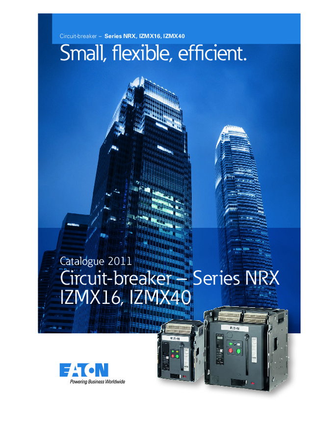
Small, fl exible, effi cient. Catalogue 2011 Circuit-breaker – Series NRX IZMX16, IZMX40 Circuit-breaker – Series NRX, IZMX16, IZMX40 11-10577-Leistungsschalter_US_EN.indd 1 11-10577-Leistungsschalter_US_EN.indd 1 20.09.11 13:06 20.09.11 13:06
CA01305001Z-EN www.eaton.com NRX Series Rated operational current from 630 to 4000 A, switching capacity 440 V AC, I cu = I cs from 42 to 105 kA, 3 or 4 pole, fixed mounted or withdrawable, electronic releases for system protection, selective, universal protection, professional protection.Extensive mounting accessories for fixed mounting and withdrawable units Motor operator IZMX…M… +++ Shunt release IZMX…ST… +++ Closing release IZMX…-SR… +++ Undervoltage release IZMX…-UV… +++ Auxiliary contact ON-OFF IZMX…-AS… +++ Latch check switch IZMX…LCS… +++ Overload trip switch IZMX…-OTS +++ Mechanical interlocks.Extensive range of control units and communication The Digitrip TM control unit offers the most extensive range of functions in its class. It covers all requirements: from simple system protection to professional protection with additional parameter, protection, measuring, analysis, diagnostics and event memory functions that can be shown on an LCD color display or transferred remotely via a communication module, displayed on a web page or sent worldwide by email. Unique in this range: the LCD color display. Digitrip can be integrated in different data networks together with Eaton’s plug & play communication modules: MODBUS, PROFIBUS or Ethernet. Circuit-breakers can then be monitored directly via the Internet.Worldwide novelty ARMS TM – greater safety for maintenance personnel In the event of an arc fault the patented ARMS TM (Arcflash Reduction Maintenance System) trips faster than a short-circuit release. In conjunction with the NRX (IZMX) series, additional components of the ARCON TM arc fault protection system offer additional arc fault protection. Eaton's NRX series is a new line of circuit-breakers up to 4000 A. Engineering and mounting requirements are reduced thanks to only two compact sizes, the modular design and standard accessories. The highlight of the NRX series: The Digitrip 1150 P trip electronics. It covers all possible applications. And in conjunction with a communica-tion module ensures that operation can be monitored from all round the globe. The innovative IZMX16 enables two circuit-breakers with a width of only 600 mm to be mounted in a switch cabinet. IZMX circuit-breakers, INX switch-disconnectors, from the NRX series up to 4000 A CA01305001Z_U2_EN.indd 2 26.09.2011 14:23:53
IZMX circuit-breakers, INX switch-disconnectors CA01305001Z-EN www.eaton.com Circuit-breakers IZMX16, switch-disconnectors INX16Circuit-breakers IZMX40, switch-disconnectors INX40up to 4000 A Technical overview Switching Capacity 2 Type code for EMEA 3 Global type code (non-EMEA) 4 Electronic releases 6 Zone selective interlocking 8 System overview IZMX16 circuit-breakers and accessories 9 IZMX40 circuit-breakers and accessories 10 Key to type references 11 Description System features 12 System features, Instruction Leaflets References 13 Components for communication 14 Ordering Basic devices Circuit-breakers IZMX16, 3 and 4 pole 15 Switch-disconnectors INX16, 3 and 4 pole 22 Circuit-breakers IZMX40, 3 and 4 pole 23 Switch-disconnectors INX40, 3 and 4 pole 33 Withdrawable units Cassettes 35 Safety shutters, Cell switches 36 Secondary terminal block kit 36 Mechanical interlock, drawout mounting 37 Replacement hand lever 37 Drawout Door Interlocks 37 Door gasket IP41, Door cover IP55 37 Electronic Releases Trip unit for system protection Type A 38 Trip unit for selective protection Type V 38 Trip unit for universal protection Type U 39 Trip unit for power measurement Type P 40 Power supply, Test device 41 Communication modules 41 PROFIBUS-DP bus connector plug 41 Rating plugs Rating plugs (Rate current modules) 42 Current sensor for neutral conductor 44 Ground Source/Zero Sequence Sensor 44 Electrical accessories Motor operator 45 Shunt releases 46 Closing releases, Latch check switches 47 Undervoltage releases 48 Time delay modules 48 Ordering Electrical accessories Auxiliary contacts 48 Overcurrent Trip switches 49 Interlocked Trip Indicators 49 Remote reset 49 Mechanical accessories Operation counters 50 Locking ON/OFF buttons 50 Key locking in safe Off 50 Door keylock 50 Mechanical interlock, fixed mounting 51 Cable kits for mechanical interlock 51 Door gasket IP41, door cover IP55 51 Terminals Main terminal sets 52 Control circuit terminal units, fixed mounting 52 General accessories Replacement coding, basic device to cassette 53 Phase barrier 53 Lifting yoke for fitting 53 Engineering Terminal assignment of control circuit terminals 54 Terminal assignment of communication wiring 56 Mechanical Interlock configurations 57 Tripping characteristics 58 Rating-plug combinations 71 Selectivity tables 72 Technical data Circuit-breakers IZMX16 76 Switch-disconnectors INX16 78 Circuit-breakers IZMX40 80 Switch-disconnectors INX40 84 Electrical accessories 88 Motor operators, altitude rating factors 89 Communication modules 90 Dimensions Circuit-breaker IZMX16, switch-disconnector INX16 Fixed mounted 91 Withdrawable units 91 Circuit-breaker IZMX40, switch-disconnector INX40 Fixed mounted 92 Withdrawable units 94 Minimum clearances 97 30˚ 30˚
Powering Business Worldwide Discover Eaton – a leader in the power management field Since 1911, when our company began trading as a small truck parts supplier, Eaton ® Corporation has come a long way. Today, as a diversified power management company, Eaton has sales of $13.7 billion USD (FY 2010), employs 70,000 people and has customers in more than 150 countries. Everyday, we help companies across the world to manage power, and do more, while consuming less energy. Eaton’s innovative products, solutions and technologies are designed to help customers to manage power and conserve resources while working more productively, safely and sustainably. Our integrated and diversified business strategy ensures that we remain at the forefront of our industry, decade after decade. Aerospace A leading global supplier to commercial and military aviation and aerospace industries. An extensive technology portfolio includes hydraulic systems, fuel systems, motion control systems, propulsion sub-systems, cockpit controls and displays and fluid health monitoring systems. Our products improve fuel economy, aircraft performance, reliability and safety. Truck A leader in the design, manufacture and marketing of complete line of drivetrain systems and components for medium- and heavy-duty commercial vehicles. Under the “Roadranger” brand, Eaton also markets lubricants, safety products and service tools. Eaton’s hybrid power systems have earned the company recognition as a global leader in alternative power for commercial vehicles. Electrical A global leader in electrical control, power distribution, uninterruptible power supply and industrial automation products and services. Our products provide customer-driven PowerChain Management ® solutions to serve the power system needs of the industrial, institutional, government, utility, commercial, residential, IT, mission critical and OEM markets worldwide. Aerospace Truck 11-10092_PUE_Vor-Nachspann_EN.indd 2 11-10092_PUE_Vor-Nachspann_EN.indd 2 19.07.11 15:55 19.07.11 15:55
Buildings Information Technology • Data centers • Telecommunication • Networks • Computer rooms • World’s most efficient line of UPSs to reduce footprint and save energy • Reliable power systems with inherent redundancy to improve availability • Power metering and monitoring to diagnose problems and lower costs • Local service and support for quick response Powering electrical systems worldwide • Residential • Healthcare • Education • Commercial offices • Retail • Public sector • Airports • Electrical distribution solutions for safe and efficient power delivery • Power quality systems for uptime and reliability • Power metering and monitoring to add intelligence and save costs • Industrial control products for HVAC applications 11-10092_PUE_Vor-Nachspann_EN.indd 4 11-10092_PUE_Vor-Nachspann_EN.indd 4 19.07.11 15:55 19.07.11 15:55
In order to meet the needs of increasingly mobile customers and employees, Eaton is offering a mobile solution for communication and product information from June 2011. Clearly designed shelf view The Eaton Catalogs app offers an outstandingly clear user interface and several fully developed functions. In the form of a shelf view, the user is provided with a clear overview of Eaton's latest product catalogues. These can be leafed through on the fly or downloaded to the device – for situations when there is no Internet access. Choose for yourself which catalogues are of interest and keep up-to-date using the Update function. Intuitive browsing, searching and finding Users can simply browse through the catalogues with intuitive navigation ensured. A linked table of contents, thumbnail views and a rapid search function are also provided for finding information quickly and conveniently. Linked data sheets It is often the case that product information is required which is not available in the product catalogues. The “Eaton Catalogs” contain article numbers and type designations that are linked to the Online Catalogue. This enables the user to access highly detailed production information in the form of a technical data sheet. From here other documents such as installation instructions and technical publications can be called up. Whether on the building site, at the customer, on the train or at home – “Eaton Catalogs” make sure that all product information is close to hand. Eaton Catalogs in the App Store – all catalogues close at hand! In the App Store from June 2011 Scan the QR code with your iPhone or iPad and you will immediately access “Eaton Catalogs“. 11-10092_PUE_Vor-Nachspann_EN.indd 22 11-10092_PUE_Vor-Nachspann_EN.indd 22 19.07.11 15:57 19.07.11 15:57
The Eaton online catalogue The catalogue portal is the entry page to the Online Catalogue. Important elements include the powerful search function and the graphical navigation. The clearly designed user interface makes the application particularly easy to use. Continuous updating ensures that you will always find the latest product data and news. http://ecat.moeller.net SELECTION AIDS THE PRODUCT GROUP TREE The product group tree:Clear layout of the Eaton productsin product groups. The one-dimensional product structure ensures the user can easily locate the product with a few clicks. The selection tools:3 clicks to product Selection-relevant features allow users to locate their products easily, without problems. From general to specifi c to product – 3 clicks! Search/result list: high performance search with suggestion list by “Entry”. A suggestion list brings the search an above-average success rate, because nothing makes less sense than a 0-hit result. THE SEARCH Eaton Appstore_Online.indd 23 Eaton Appstore_Online.indd 23 21.07.11 11:22 21.07.11 11:22
2 IZMX circuit-breakers, INX switch-disconnectors Switching capacity CA01305001Z-EN www.eaton.com Switching capacity Type code for Eaton IEC-ACB for EMEA (Europe, Middle-East, Africa) IZMX16, INX16 IZMX40, INX40 I cu /I cs at U e = 440/690 V AC Basic switching capacity (B) Normal switching capacity (N) High switching capacity (H) I cu : Rated ultimate short-circuit breaking capacity at rated operational voltage U e I cs : Rated service short-circuit breaking capacity at rated operational voltage U e Circuit-breakerSeries NRX Rated operational current I n A 440 V AC I cu / I cs kA/kA 690 V AC I cu / I cs kA/kA 440 V AC I cu / I cs kA/kA 690 V AC I cu / I cs kA/kA 440 V AC I cu / I cs kA/kA 690 V AC I cu / I cs kA/kA IZMX16 NF-Frame 630 - 1600 42/42 42/42 50/50 42/42 65/50 42/42 IZMX40 RF-Frame 800 - 4000 66/66 66/66 85/85 75/75 105/105 85/85 I cw at U e = 440/690 V AC Basic switching capacity (B) Normal switching capacity (N) High switching capacity (H) I cw at t = 1 s I cw : Rated short-time withstand current Circuit-breaker,switch-disconnector Rated operational current I n A 440/690 V AC I cw kA 440/690 V AC I cw kA 440/690 V AC I cw kA IZMX16 NF-Frame 630 - 1600 42 42 42 IZMX40 RF-Frame 800 - 4000 66 75 85 I cm at U e = 440/690 V AC Basic switching capacity (B) Normal switching capacity (N) High switching capacity (H) I cm : Rated short-circuit making capacity (Peak value) at rated operational voltage U e Switch-disconnectorsSeries NRX Rated operational current I n A 440/690 V AC I cm kA 440/690 V AC I cm kA 440/690 V AC I cm kA INX 16 NF-Frame 630 - 1600 88 – – INX 40 RF-Frame 800 - 4000 144 165 – IZMX16, INX16, IZMX40, INX40
IZM circuit-breakers, IN switch-disconnectors Type code for Eaton IEC-ACB for EMEA (Europe, Middle-East, Africa) CA01305001Z-EN www.eaton.com 3 IZMX 16 B 3 - A 06 W INX 40 N 4 V 08 F H U 10 P 121620253240 IZMX = IEC circuit-breakerINX = IEC switch-disconnectors Frame size16: IZMX16, INX16, 630-1600 A40: IZMX40, INX40, 800-4000 A Switching capacityB = BasicN = NormalH = High Number of poles3: 3 pole4: 4 pole CharacteristicA = System protectionDigitrip 520 LIV = Selective protectionDigitrip 520 LSIU = Universal protectionDigitrip 520M LSIP = U + Power MeasurementDigitrip 1150i LSI Rated current06: 630 A08: 800 A10: 1000 A12: 1250 A16: 1600 A20: 2000 A25: 2500 A32: 3200 A40: 4000 A ModelW = WithdrawableF = Fixed IZMX16, INX16, IZMX40, INX40
4 IZMX circuit-breakers, INX switch-disconnectors Type Code for Eaton IEC-ACB global (non-EMEA) CA01305001Z-EN www.eaton.com Type Code for Eaton IEC-ACB global (non-EMEA) Position 1-8 Basic Device Selection Position 9-11Overcurrent Protection Position 12-20 Options & Accessories Pos: 1 2 3 4 5 6 7 8 9 10 11 12 13 14 15 16 17 18 19 20 Type Code Example: R E S 8 4 0 3 W 5 2 G A B A N 4 X N D X Basic Device Selection Overcurrent Protection, Rating Plug Selection Postion 1-8 Position 9, 10 Electronic Trip Unit Selection Position Protection ZSI ARMS Position 1 - Breaker Frame Size No Protection - Switch Disconnector N Type NF 630 to 1600 A SW None R Type RF 800 to 4000 A Digitrip 520 - System Protection Position 2 - Industry Standard 22 LI protection only LI E IEC 60947-2 Digitrip 520 - Selective Protection Position 3, 4 - Switching Capacity 52 LSI (G) LSI – at 440 V AC (IEC) 53 - ZSI Optional LSI ZSI S4 42 kA 5G LSIG – S5 65 kA 5H LSIG ZSI S6 65/66 kA S8 85 kA Digitrip 520M - Universal Protection SC 105 kA M2 LSI – – M3 LSI(G/A) LSI ZSI – Position 5, 6 - Rated Operational Current MA - Metering LSIA- Communications Ready- Ext. Power Ready 24V DC- ZSI Optional- ARMS Optional LSIA – – 07 630 A Frame MB LSIA ZSI – 08 800 A Frame MG LSIG – – 10 1000 A Frame MH LSIG ZSI – 13 1250 A Frame R2 LSI – ARMS 16 1600 A Frame R3 LSI ZSI ARMS 20 2000 A Frame RA LSIA – ARMS 25 2500 A Frame RB LSIA ZSI ARMS 32 3200 A Frame RG LSIG – ARMS 40 4000 A Frame RH LSIG ZSI ARMS Position 7 - Poles & Phasing 3 3-Pole ABC 4 4-Pole NABC Digitrip 1150i - Power Measurement 12 520M Protection + LCD Color DisplayAdvanced metering & protective features LSI – – Position 8 - Mounting Configuration 13 LSI ZSI – B Fixed 14 LSIGA – – W Withdrawable 15 LSIGA ZSI – 16 LSI – ARMS 17 LSI ZSI ARMS 18 LSIGA – ARMS 19 LSIGA ZSI ARMS Position 11Rating Plug [A] 0 Non-Auto Switch 1 200 2 250 3 300 4 400 5 500 7 630 8 800 A 1000 C 1250 D 1600 M 2000 N 2500 Q 3200 R 4000
IZMX circuit-breakers, INX switch-disconnectors Type Code for Eaton IEC-ACB global (non-EMEA) CA01305001Z-EN www.eaton.com 5 Position 1-8 Basic Device Selection Position 9-11Overcurrent Protection Position 12-20 Options & Accessories Pos: 1 2 3 4 5 6 7 8 9 10 11 12 13 14 15 16 17 18 19 20 Type Code Example: R E S 8 4 0 3 W 5 2 G A B A N 4 X N D X Options & Accessories Position 17 Postion 9-20 Trip Indicator Bell Alarm/OTS Secondary Terminal Blocks Remote Reset Position 12 - Shunt Trip N None None Per Breaker Options – N No Shunt Trip X Trip Indicator None Per Breaker Options – A 110-127 V AC/DC Z Trip Indicator 2 Form C Per Breaker Options – R 208-240 V AC/DC M Interlock Trip Indicator None Per Breaker Options – L 24 V DC A Interlock Trip Indicator None Per Breaker Options 24 V AC H 48 V DC B Interlock Trip Indicator None Per Breaker Options 120 V AC S 60 V DC C Interlock Trip Indicator None Per Breaker Options 240 V AC Y Interlock Trip Indicator 2 Form C Per Breaker Options – Position 13 - Motor Operator D Interlock Trip Indicator 2 Form C Per Breaker Options 24 V RR M Manually Operated E Interlock Trip Indicator 2 Form C Per Breaker Options 120 V RR B 110-125 V AC/DC F Interlock Trip Indicator 2 Form C Per Breaker Options 240 V RR T 208-250 V AC/DC 1 None None Full-Compliment – L 24 V DC 2 Trip Indicator None Full-Compliment – H 48 V DC 3 Trip Indicator 2 Form C Full-Compliment – S 60 V DC 4 Interlock Trip Indicator No OTS Full-Compliment – J Interlock Trip Indicator No OTS Full-Compliment 24 V RR Position 14 K Interlock Trip Indicator No OTS Full-Compliment 120 V RR Spring Release Latch Check Switch L Interlock Trip Indicator No OTS Full-Compliment 240 V RR S Interlock Trip Indicator 2 Form C Full-Compliment – N No Spring Release No LCS R Interlock Trip Indicator 2 Form C Full-Compliment 24 V RR A 110-127 V AC/DC No LCS S Interlock Trip Indicator 2 Form C Full-Compliment 120 V RR B 110-127 V AC/DC Spring Release LCS T Interlock Trip Indicator 2 Form C Full-Compliment 240 V RR C 110-127 V AC/DC LCS Wired External R 208-240 V AC/DC No LCS Position 18 - PadLocking, Operations Counter S 208-240 V AC/DC Spring Release LCS N No PB Covers No Counter T 208-240 V AC/DC LCS Wired External A No PB Covers Counter Provided L 24 V DC No LCS B PB Covers (plastic/plastic) No Counter P 24 V DC Spring Release LCS J PB Covers (plastic/plastic) Counter Provided Q 24 V DC LCS Wired External K PB Covers (metal/metal) No Counter H 48 V DC No LCS L PB Covers (metal/metal) Counter Provided J 48 V DC Spring Release LCS 5 PB Covers (metal/metal), Safe-Off No Counter K 48 V DC LCS Wired External 6 PB Covers (metal/metal), Safe-Off Counter Provided 1 60 V DC No LCS 2 60 V DC Spring Release LCS Position 19 - Drawout Breaker Options 3 60 V DC LCS Wired External Breaker configuration Shutters Terminal Adapters D Drawout Breaker Shipping Alone n/a None Position 15 - UVR / Second Shunt Trip C Drawout Breaker in Cassette None No Terminals N None 1 Drawout Breaker in Cassette None Vertical A 110-125 V AC/DC UVR 2 Drawout Breaker in Cassette None Horizontal R 220-250 V AC/DC UVR 8 Drawout Breaker in Cassette None Front Connect L 24 V DC UVR H 48 V DC UVR 9 Drawout Breaker in Cassette Shutters No Terminals S 60 V DC UVR 4 Drawout Breaker in Cassette Shutters Vertical 1 110-127 V AC/DC Second Shunt Trip 5 Drawout Breaker in Cassette Shutters Horizontal 2 208-240 V AC/DC Second Shunt Trip 7 Drawout Breaker in Cassette Shutters Front Connect 4 24 V DC Second Shunt Trip 8 48 V DC Second Shunt Trip Position 19 - Fixed-Mount - Terminal Adapater Options 9 60 V DC Second Shunt Trip K None (Terminals recomended for 4000A frame) F Vertical Position 16 - Auxiliary Switches H Horizontal N No Aux Switches B Front Connect 2 2 Form C 4 4 Form C Position 20 6 6 Form C X Future 8 8 Form C A 10 Form C W 12 Form C
6 IZMX circuit-breakers, INX switch-disconnectors Electronic releases CA01305001Z-EN www.eaton.com Electronic releases Standard protection Standard plus selectivity Universal protection Professional protection Type Coding Digitrip 520 LIIZMX-DTA Digitrip 520 LSIIZMX-DTV Digitrip 520M LSIIZMX-DTU Digitrip 1150i LSIIZMX-DTP Current Range 200 - 4000 A 200 - 4000 A 200 - 4000 A 200 - 4000 A RMS Value Monitoring ● ● ● ● Protective functions General Ordering options LI LSI; LSIG LSI; LSIG; LSIA LSI; LSIG Rating plug (I n ) ● ● ● ● Overtemperature trip ● ● ● ● Overload protection L Overload trip I r (0.5 - 1.0) x I n (0.5 - 1.0) x I n (0.5 - 1.0) x I n (0.5 - 1.0) x I n Long delay time at 6 x I r (I 2 t Curve) t r 2 - 24 s 2 - 24 s 2 - 24 s 2 - 24 s Long delay time at 6 x I r (I 4 t Curve) t r – – – 1 - 5 s IEC Type A, B, C curves – – – – ● High load alarm – – – ● 2) Off, 0.5 - 1.0 x I r Thermal memory (enable / disable) – ● ● ● ● Short-time delayedShort-circuit protection S Short delayed pickup short-circuit protection I SD – (2 - 10) x I r (2 - 10) x I r (2 - 10) x I r Short delay time at 8 x I r (I 2 t Curve) t SD – 100 - 500 ms 100 - 500 ms 100 - 500 ms Short delay time, flat characteristic curve t SD – 100 - 500 ms 100 - 500 ms 100 - 500 ms Zone selectivity ZSI – – ○ ○ ○ Non-delayed short-circuit protection I Non-delayed short-circuit protection (2 - 12) x I n (2 - 12) x I n (2 - 12) x I n (2 - 12) x I n Switch-off function – ● ● ● Closing releases MCR ● ● ● ● Optional ground fault protection G – ○ ○ ○ Ground/Earth fault alarm – A – – ○ 1) ○ 1) Ground/Earth fault protection release Ig – (0.25 - 1.0) x I n 3) (0.25 - 1.0) x I n 3) (0.24 - 1.0) x I n Short delay time at 0.625 x I n (I 2 t curve) tg – 100 - 500 ms 100 - 500 ms 100 - 500 ms Short delay time, flat characteristic curve tg – 100 - 500 ms 100 - 500 ms 100 - 500 ms Zone selectivity ZSI – – ○ ○ ○ Thermal memory – – ● ● ● Disable ground fault protection – – – – ● Neutral protection N ● ● ● ● Notes l n = rating plug (rate current module) = rated operational current transformer l r = Set value overload trip (= rated operational current of system) 1) Requires external 24 V DC control voltage supply. 2) High load alarm available only on LSI styles, active at 85% of I r 3) Limited to 1200 A 4) Hand-held kits available for basic verification or advanced testing 5) Captures fault current of latest event when control power is supplied ● Standard○ Optional– not available IZMX16, INX16, IZMX40, INX40
IZMX circuit-breakers, INX switch-disconnectors Electronic releases CA01305001Z-EN www.eaton.com 7 Standard protection Standard plus selectivity Universal protection Professional protection Type Coding Digitrip 520 LIIZMX-DTA Digitrip 520 LSIIZMX-DTV Digitrip 520M LSIIZMX-DTU Digitrip 1150i LSIIZMX-DTP Current Range 200 - 4000 A 200 - 4000 A 200 - 4000 A 200 - 4000 A RMS Value Monitoring ● ● ● ● Protective functions System diagnostic Status/Overload LED ● ● ● ● Cause of trip LEDs ● ● ● ● Current at trip point (display indication) – – ● 1) ● 1) Ground fault release/alarm remote signaling (relay contact) – – ● 1) ● 1) Overload alarm monitoring – – ● 1) ● 1) Programmable contacts – – – ● System monitor Digital display – – 4-digit LCD LCD Color Graphic Metering Accuracy – – ● +/- 2%, full scale 6) ● +/- 1% of reading Voltage (%) L to L – – – ● +/- 1% of reading Power and energy (%) – – – ● +/- 2% of reading Apparent power kVA and demand – – – ● Reative power kVAR – – – ● Power factor – – – ● Crest factor – – – ● Power quality - harmonics – – – ● % THD – – – ● Communications Field Bus Type – – Optional: Profibus, Modbus, INCOM, Ethernet Optional: Profibus, Modbus, INCOM, Ethernet Power supply requirement +24 V DC, optional +24 V DC, optional +24 V DC +24 V DC Additional funtions Test Capability 4) – Hand-Held Test Kit Hand-Held Test Kit Integral, Hand-Held Test Kit Maintenance Mode ARMS(Arc Flash Reduction Maintenance System TM ) – – ○ 1) ○ 1) Trip log – – ● 5) ● Electronic operations counter – – – ● Waveform capture – – – ● Breaker health monitor – – – ● Protective relay functions – – – ● Notes l n = rating plug (rate current module) = rated operational current transformer l r = Set value overload trip (= rated operational current of system) 1) Requires external 24 V DC control voltage supply. 2) High load alarm available only on LSI styles, active at 85% of I r 3) Limited to 1200 A 4) Hand-held kits available for basic verification or advanced testing 5) Captures fault current of latest event when control power is supplied 6) IZMX16 (NF-Frame) Full Scale = 1600 A IZMX40 (RF-Frame) Full Scale = 4000 A● Standard○ Optional– not available IZMX16, INX16, IZMX40, INX40
CA01305001Z-EN www.eaton.com IZMX circuit-breakers, INX switch-disconnectors IZMX circuit-breakers, INX switch-disconnectors 8 IZMX circuit-breakers, INX switch-disconnectors Zone Selective Interlocking 3 2 1 ZSI ZSI ZSI ZSI ZSI Zone 1 Zone 2 Zone 3 CB 2 t sd = 200 ms t sd = 300 ms t sd = 200 ms t sd = 100 ms t sd = 100 ms CB 3 CB 5 CB 4 CB 1 M CB = Circuit BreakerZSI = Zone Selective Interlocking Zone Selective Interlocking • Zone Selective Interlocking (ZSI) is described in the soon to be pub-lished standard IEC 61912-2 Low voltage switchgear and controlgear. • The term zone selective interlocking is used to describe a method of con-trolling circuit breakers to provide selectivity with very short interrup-tion times for the breaker closest to the fault. • There are different levels (zones) of protection that isolate the fault in the distribution system. • ZSI may be applied for faults be- tween phases or earth-faults or both. • ZSI is applied to the short time faults where time selectivity can be achieved with the breakers be-tween the zones. • Because ZSI does not require auxil- iary power or additional modules to operate set up time is minimal and application is easy. Zone Selective Interlocking Example Example A – Short-circuit at position 3• Circuit-breakers CB1, CB3, CB4 all see the short circuit current and register a short delay pick-up. • Circuit breaker CB4 sends a ZSI out- put blocking signal to CB3 ZSI input. CB3 sends a ZSI output blocking sig-nal to CB1 ZSI input. CB1 sends a ZSI output signal that is not wired. This signal could be wired to a MV relay on the other side of the trans-former with a compatible ZSI cir-cuitry. • CB1 registers the ZSI input signal and starts its timer for 300ms. CB3 registers the ZSI input signal and starts its timer for 200ms. CB4 gets no input from any lower zone circuit breaker. This breaker will then trip immediately without any time delay. CB4 interrupts the fault and CB1 and CB3 stop short delay timing because the fault current is gone. • If for some reason CB4 does not open and interrupt the fault then at the end of the its short delay time CB3 will open and interrupt the fault. Example B – Short-circuit at position 2• Circuit-breakers CB1, CB3, see the short circuit current and register a short delay pick-up. CB4 and CB5 do not see the fault current and do not send a ZSI output. • Circuit breaker CB3 sends a ZSI out- put blocking signal to CB1 ZSI input. CB1 sends a ZSI output signal. In this example that signal is not wired. • CB1 registers the ZSI input signal and starts a timer for 300ms. CB3 gets no input from any lower zone circuit breaker. This breaker will then trip immediately without any time delay. CB3 interrupts the fault and CB1 stops short delay timing be-cause the fault current is gone. The clearance time is reduced by ap-proximately 150ms. Example C – Short-circuit at position 1• Only Circuit breaker CB1sees the short circuit current and registers a short delay pick-up. CB2, CB3, CB4 and CB5 do not see the fault current and do not send ZSI outputs. • CB1 sends a ZSI output signal. In this example that signal is not wired. • CB1 gets no input from any lower zone circuit breaker. This breaker will then trip immediately without any time delay. CB1 interrupts the fault and the clearance time is re-duced by approximately 250ms. IZMX16, INX16, IZMX40, INX40
9 IZMX circuit-breakers, INX switch-disconnectors CA01305001Z-EN www.eaton.com CA01305001Z-EN www.eaton.com IZMX circuit-breakers, INX switch-disconnectors 5 10 11 12 8 1 13 2 3 3 6 21 27 20 16 17 14 15 18 25 26 24 23 7 3 4 9 19 IZMX40 6 9 7 5 1 3 4 2 8 IZMX16 22 22 10 IZMX16, INX16, IZMX40, INX40 IZMX16, INX16, IZMX40, INX40
CA01305001Z-EN www.eaton.com IZMX circuit-breakers, INX switch-disconnectors 11 IZMX Circuit-breaker 1 IZMX16: 630 - 1600 AIZMX40: 2000 - 4000 A→ page 15 Cassette for withdrawable units 2 With and without control circuit terminals→ page 35 Main terminal sets 3 Universal terminals, 3- and 4-polehorizontal/vertical→ page 52 Cassette safety shutters 4 Shutter for 3- and 4-pole→ page 36 Motor operator 5 Automatic charging of the spring force storage for remote or local operations→ page 45 Current sensor for neutral conductor 6 Current sensor for sensing the neutral-conductor-current.→ page 44 Levering tool 7 Convenient collapsible lev-in tool for lev-in and out operation of the Breaker in and out of the Cassette. The lev-in tool is stored inside the breaker.→ page 53 Position cell switches 8 Cell switch signals the position of the breaker inside of the cassette. Con-nect, Test and Disconnect Position.→ page 36 Door escutcheon 9 Closes the gap between Breaker and Switchgear-door. IP41.→ page 51 Communication modules 10 Profibus DP, Modbus, Ethernet→ page 41 Control circuit terminal units 11 Either 8, 20 or 30 units→ page 52 Latch check switch 12 For use with closing release.→ page 47 Latch check switch 13 For external application usage.→ page 47 Closing releases 14 Closes the breaker by an electrical signal.→ page 47 Key locking 15 Locking of the breaker by a keylock.→ page 50 Shunt releases 16 Opens the breaker by an electrical signal.→ page 46 Undervoltage releases 17 Opens the breaker by a voltage-drop in the control-circuit.→ page 48 Red-pop trip indicator 18 Red-pop trip indicator signals a trip of the breaker by the trip unit.→ page 49 Trip indicator switches 19 Overcurrent trip switch (OTS) signals a trip by the trip unit.→ page 49 Switching operations counters 20 Counts the number of operations.→ page 50 Auxiliary contacts 21 Signalling switch ON-OFF→ page 48 Locking facilities 22 Padlockable plastic or metal front covers for ON-OFF pushbuttons.→ page 50 Spare trip unit 23 Digitrip 520; A-type→ page 38 Spare trip unit 24 Digitrip 520LSI; V-type→ page 38 Spare trip unit 25 Digitrip 520M; U-type→ page 39 Spare trip unit 26 Digitrip 1150i; P-type→ page 40 Rating plug 27 Reduces the Rated Current of the breaker.→ page 42 IZMX16, INX16, IZMX40, INX40
CA01305001Z-EN www.eaton.com 12 IZMX circuit-breakers, INX switch-disconnectors IZMX circuit-breakers, INX switch-disconnectors IZMX circuit-breakers, INX switch-disconnectors Space-saving circuit-breakers with useful accessories Eaton Introduces Series NRX! The new NRX series from Eaton is a new series of air circuit-breakers with an extensive range of accessories. The new range provides users with two compact frame sizes up to 4000A, modular design, common accessories, easy to integrate communications and a full range of trip units including the new powerful high end 1150 Digitrip trip unit with a full color LCD display. The innovative concept of the IZMX16 makes it possible to install two with-drawable circuit-breakers in a 600 mm wide section. This enables more eco-nomical section design and also saves operating space. The compact modu-lar design of the IZMX40 offers cus-tomers a full range of high performance ratings in a single frame size simplifying the integration pro-cess into panel boards and switch boards. Series NRX, a new generation and new standard in circuit protection. Applications The circuit breakers can be used in four main application areas depending on the type of equipment to be protect-ed:• System protection• Motor protection• Transformer protection• Generator protectionThese key applications make different demands on the switches, which are met with a range of control units. Switches with closing releaseThey are particularly suitable for syn-chronization tasks.Coupler switchesIn addition to the circuit-breakers, switch-disconnectors are also avail-able. These are used, for example, as coupler switches between different power supplies. The switch-discon-nectors are used as coupler switches for different sections of a network in conjunction with our automatic net-work switching device. Modular Design, Common Accessories The retrofitting of accessories is made considerably easy thanks to the effi-cient “plug & work” technology. Ac-cessory drawers and snap-fit mechanisms make it possible to fit the latest accessories with virtually no tools. This flexibility allows you to re-spond easily to changing requirements within your system. Most accessories for Series NRX are common to both the compact and standard frame sizes. Standard scope of delivery • With the new Series NRX range, you select a basic device that is already fitted with an electronic release. • The standard mounting for both frames is on a horizontal mounting plate or on horizontal traverses in the switching cabinet. The IZMX16 can also be fastened to vertical mounting plates. • With four-pole devices, the neutral conductor is arranged on the left (front view). • The neutral conductor can be load- ed 100% like the phase conductors. • The circuit-breakers are provided with a standard mechanical reclos-ing lockout. After an overload trip, the fault is usually examined first. After the fault is identified and recti-fied, the mechanical reclosing lock-out is reset by pressing the red mechanical trip indicator on the front of the circuit-breaker. • A “remote-reset” feature and an “automatic reset” are offered as ad-ditional ordering options. The re-mote reset enables resetting the breaker after an over current trip via a control voltage. The automatic re-set option enables the circuit break-er to be restored to normal operation immediately after an over current trip (i.e. there is no mechan-ical reclosing lockout). In these ap-plications compulsory fault analysis is intentionally avoided. • The number of secondary control cable terminals depends on the ac-cessories fitted. • If a cassette is ordered without the basic device, this can be already fit- ted with the maximum number of control cable terminals. For greater economy in large plants, the cas-sette is also offered without control circuit terminals so that fitting can be carried out later at the installa-tion or when accessories are re-quired at a later time.. • The withdrawable basic device in- cludes the primary finger clusters and levering-in mechanism. NOTE: Some manufacturers mount the pri-mary finger clusters inside the cas-sette cell, which requiring shutdown of the panel board for inspection and maintenance. • 2 changeover contacts are provided as standard for ON/OFF status indi-cation. • A coding mechanism between the basic device and the cassette pre-vents impermissible combinations (“Rejection Interlock”). • The door escutcheon is always in- cluded in the scope of delivery. With withdrawable designs this is sup-plied with the cassette (withrawable unit). • On withdrawable units the circuit breaker can be pulled out to inspect the arc chutes. With fixed units, it is recommended that sufficient space is provided above the circuit break-er to enable inspection. An addi-tional cover is not required. • All basic devices that are provided with universal protection (Digitrip 520M), feature a 4-digit LCD display, and all devices provided with power measurement protection feature a full color LCD display. • On each circuit-breaker the inte- grated Digitrip electronic release is factory fitted with a sealable protec-tive cover. • If a motor operator is ordered, the “Spring-operated stored energy mechanism tensioned” indicator switch is automatically provided. Additional benefits Series NRX • The “universal” design of the main terminal offers maximum flexibility. The horizontal terminal can be rotat-ed simply at the installation so that it can also be used as a vertical con-nection. With withdrawable units, additional terminal pieces can even be dispensed with. Both the Series NRX breaker and the cas-sette offer an integrated flange ter-minal to which the system busbars can be connected directly. For this reason, the main terminal pieces for Series NRX are not part of the stan-dard scope of delivery. Don’t forget to order additionally required termi-nal pieces if required. • Thanks to the separate mounting position, a switching operations counter can now be used also inde-pendently of a motor operator. • Withdrawable unit operation: The unit is actuated with a hand crank supplied as a standard feature and has a secure position in the basic device. External 24 V supply • The standard protection functions of Series NRX operate independently of an external control voltage sup-ply. The power supply of the elec-tronics unit, for example for overload and short-circuit protec-tion, is implemented via the current transformers integrated in the cir-cuit-breaker. • The universal and power measure- ment release units with display can be fed with a 24 V DC supply so that the display function can be used without a load. An external 24 V DC power supply is needed if communi-cation functions are required CurveSelect characteristics program Display characteristic curves accord-ing to specific settings and assess their interaction effectively: www.moeller.net/de/support
CA01305001Z-EN www.eaton.com IZMX circuit-breakers, INX switch-disconnectors IZMX circuit-breakers, INX switch-disconnectors 13 Communication capability The communication-capability of Se-ries NRX circuit-breakers open up new possibilities in power distribution. The trip unit provides all important op-eration information and passes this on via one of the various communication adapter modules. This increases sys-tem transparency and shortens the re-sponse times to states such as overcurrent, phase asymmetry and overvoltage. A rapid intervention in a process can, for example, prevent downtimes and help to schedule main-tenance activities and therefore boost plant availability. Series NRX offers interface modules to support protocols such as Modbus RTU, Profibus, and INCOM. In addition Eaton also offers a direct connect Ethernet Communica-tions module that provides web en-abled monitoring and control of the trip unit metering, logging, alarms, and control functions using a standard web browser. Greater safety for maintenance personnel with ARMS™ Personnel safety is of paramount im-portance in today’s work environment. Of recent concern is the potential for serious injury due to exposure to elec-trical arcs. Eaton’s Series NRX trip units offer the patented ARMS system (Arcflash Reduction Maintenance System™), which offers a non-delayed immediate disconnection is in the event of an arc fault. This disconnec-tion is even faster than that of a non-delayed short-circuit release. This function can be activated directly on the circuit-breaker or via an external switch, such as when maintenance personnel enter a hazardous area. Major Benefits of ARMS:• Increased personnel safety – by lim- iting the available arc flash energy • Simple to operate• Enabled with circuit breaker door closed by a door mounted lockable switch • Enabled only for the time required to perform the desired maintenance work • Preserves overcurrent coordination under normal conditions • Reduction in incident energy levels may permit reduced levels of Per-sonal Protective Equipment (PPE), therefore improving worker comfort and mobility Other components of the ARCON arc fault protection system, in conjunction with Series NRX, enable an expansion of arc fault protection in stages. ARCON on the Internet: www.moeller.net/arcon Selection criteria for circuit-breakers Fundamental criteria for the selection of circuit-breakers:• Max short-circuit current I k max at the circuit-breaker’ point of installa-tion: this value determines the short-circuit breaking capacity or the short-circuit current carrying ca-pacity of the circuit-breaker. It is compared with the I cu , I cs and I cw values of the switch and essentially determines its size (see technical data). • Rated operational current I n which should flow through the respective branch circuit: This value must not be greater than the maximum switch rated operational current of the cir-cuit-breaker. The rated operational current can be adjusted down using additional rated operational current modules. • Ambient temperature of the circuit breaker: This is generally the inter-nal temperature in the control panel. Observe the derating values with in-creased ambient temperature (see Technical data). • Circuit-breaker type: fixed mounted or withdrawable units, 3 or 4 pole. • Minimum short-circuit current, which flows through the switching device: The release must recognize this value as a short-circuit and may react with a trip. • Protection functions of the circuit breaker: This is determined by the selection of the respective overcur-rent release. For additional resources and tools for selecting Eaton Air Circuit Breakers please visit us as www.eaton.com/seriesnrx. IL Reference Listing Description Frame Publication Number Description Frame Publication Number Description Frame Number Description Frame Number IL for rating plug NF and RF 70C1592 IL for cassette extension rails RF IL01301047E IL for drawout circuit breaker cassette rejection interlocks NF and RF IL01301006E IL for breaker and cassette interphase barriers RF IL01301048E IL for auxiliary switch in right accessory tray NF IL01301007E IL for CES key lock NF IL01301049E IL for UVR/ST/OTS in left accessory tray NF and RF IL01301008E IL for Castell key lock NF IL01301050E IL for spring release, latch check switch and motor operator NF and RF IL01301010E IL for Digitrip 520 and 520M NF and RF IL01301051E IL for operation counter NF IL01301011E IL for Ethernet communications adapter module NF and RF IL01301052E IL for door escutcheon and gasket kit NF and RF IL01301012E IL for rear primary adapters RF IL01301053E IL for drawout cassette IP20 safety shutters NF IL01301013E IL for cassette cell switch RF IL01301054E IL for fixed breaker arc hood NF IL01301014E IL for operation counter RF IL01301055E IL for fixed breaker primary adapters NF IL01301015E IL for front primary adapters RF IL01301056E IL for drawout breaker primary adapters NF IL01301016E IL for auxiliary switch in right accessory tray RF IL01301057E IL for drawout levering (racking) mechanism NF and RF IL01301018E IL for mechanical pop-out indicator and inter-locked indicator NF and RF IL01301058E IL for mechanical pop-out indicator and inter-locked indicator NF IL01301019E IL for CES key lock RF IL01301059E IL for breaker and cassette interphase barriers NF IL01301019E IL for Ronis key lock RF IL01301060E IL for cassette extension rails NF IL01301025E IL for Castell key lock RF IL01301061E IL for mounting feet NF IL01301030E IL for Kirk Key Lock RF IL01301062E IL for source ground/zero sequence ground sen-sor NF and RF IL01301031E IL for 1150 trip unit NF and RF IL01301064E IL for neutral current sensor NF IL01301032E IL for pushbutton cover kit RF IL01301065E IL for INCOM communications adapter module NF and RF IL01301033E IL for handheld test kit NF and RF IL01301067E IL for Modbus communications adapter module NF and RF IL01301034E IL for drawout circuit breaker 2-way cable inter-lock kit NF IL01301069E IL for PROFIBUS communications adapter module NF and RF IL01301035E IL for drawout circuit breaker 3-way cable inter-lock kit NF IL01301070E IL for surface mount NF IL01301036E IL for fixed circuit breaker 2-way cable interlock kit NF IL01301071E IL for fixed and drawout breaker secondary termi-nal blocks NF and RF IL01301037E IL for fixed circuit breaker 3-way cable interlock kit NF IL01301072E IL for IP55 cover NF and RF IL01301038E IL for cassette door interlock NF IL01301073E IL for Kirk key lock NF IL01301039E IL for handheld test kit NF and RF IL5721B13 IL for ronis key lock NF IL01301040E IL for time delay undervoltage module NF and RF IL5721B33 IL for pushbutton cover kit NF IL01301041E Series NRX low voltage power (air) circuit break-ers NF MN01301001E IL for cassette cell switch NF IL01301043E Series NRX low voltage power (air) circuit break-ers RF MN01301003E IL for drawout cassette IP20 safety shutters RF IL01301044E IL for Lev-In key locks (Kirk, CES, Ronis, Castell) RF IL01301063E IL for neutral current sensor RF IL01301046E IL for remote reset RF IL01301068E Note For more information on Series NRX, please visit www.eaton.com/seriesnrx.
CA01305001Z-EN www.eaton.com 14 IZMX circuit-breakers, INX switch-disconnectors IZMX circuit-breakers, INX switch-disconnectors Communication Options for Series NRX For the Series NRX range, PROFIBUS-DP or Modbus RTU communication protocols are supported by optional fieldbus connection accessories. Communication adapter modules are compact units for direct mounting in the auxiliary terminal strip. When retrofitting, four auxiliary terminals are replaced with one communication module. The terminals provide all data available in the trip unit to the fieldbus, including switching state, current, voltage, power, energy, and diagnostic information such as overcurrent, phase asymmetry and overvoltage as measured by trip unit. Through the communication module the trip unit maintenance mode can be enabled and the breaker can also be opened and closed via the Spring Release and Shunt Trip when wired accordingly. In addition to PROFIBUS-DP and Modbus RTU, Series NRX also offers an additional communication module for direct Ethernet connection to the circuit breaker. The Ethernet adapter module supports web enabled browsing direct from the module and supports Simple Network Mail Protocol (SNMP) for alarm or event notifications. Requirements The communication adapter modules can be used in combination in both NF and RF Frame breakers (IZMX16/40) and in combination with Digitrip trip units with Metering and Power Measurement capability:• Digitrip 520M (… -U Types)• Digitrip 1150i (…-P Types) Configuration PROFIBUS-DP configuration Communications module IZMX-PCAM has a 9-pin D-Sub socket for connection to PROFIBUS. The module works as a slave on PROFIBUS-DP; the data is defined through a standardized device master data file, which permits smooth integration of IZMX in a DP line.• On the PROFIBUS-DP side the module supports automatic baud rate detection; the PROFIBUS-DP bus address is set through the trip unit’s display. The maximum cable length is 2.4 km. • To operate the IZMX-PCAM, a supply voltage of 24 V DC is required.• The data connection to the circuit-breaker is implemented internally through a serial highspeed data connection. Data access via PROFIBUS-DPThe data on PROFIBUS-DP are offered according to the profile for low-voltage switchgear (LVSG) of PROFIBUS International (PROFIBUS and PROFINET User Group). Five different data structures with varying numbers of parameters are available through the device master data file. This allows a data filter to be easily implemented, which simplifies integration of the Series NRX data into the control system. ① ② ③ ② IZMX-PCAM: PROFIBUS-DP ① IZMX-MCAM: Modbus ③ IZMX-ECAM: Ethernet PROFIBUS Control Source Ground EnableDisable Series NRX PROFIBUS Communications Adapter Module Cat. PCAM Modbus Control Source Ground EnableDisable Modbus Communications Adapter Module Cat. MCAM Ethernet Control Source Ground EnableDisable Series NRX Ethernet Communications Adapter Module Cat. ECAM alternative NF frame, IZMX16RF frame, IZMX40 with U or P release Modbus configuration Communications module IZMX-MCAM has a plug-in screw terminal for connection to Modbus. The module operates as a Modbus slave.• Baud rate, data format and address (max. 247) for Modbus are set with the input keys of the trip unit. The maximum cable length is 1.2 km. • The Modbus must be terminated with a 120 Ω terminating resistor.• To operate the IZMX-MCAM, a supply voltage of 24 V DC is required.• The data connection to the circuit-breaker is implemented internally through a serial highspeed data connection. Data access via ModbusThe data is contained in comprehensive data tables. Each data point is available as floating-point (IEEE) or fixed-point value. This variance allows the integration of the IZMX to be adapted to the Modbus architecture. This enables a simple means of implementing a data filter, which facilitates the integration of IZMX data in the control system. Ethernet configuration Communications module IZMX-ECAM has standard RJ45 socket for connection to Ethernet. This module has a configured web server on board and supports Simple Network Mail Protocol (SNMP) for alarm or event notifications.• IP address and related parameters are set through the trip unit’s display.• The data connection to the circuit-breaker is implemented internally through a serial high speed data connection. • To operate the IZMX-ECAM, a supply voltage of 24 V DC is required. Data access via EthernetThe data is contained in different web pages structured according to the topics „Data View”, „Alarms”, „Logs” and „Configuration”. This variance allows the integration of the IZMX to be adapted to all Ethernet networks supporting http protocol. An „around the world access” to the breaker becomes reality and using the SNMP protocol alarm messages can be transported everywhere. Documentation All instruction leaflets can be found online at www.eaton.com/seriesnrx/ Installation and general usage instruction leaflet forIZMX-MCAM: IL01301034E (deutsch/english)IZMX-PCAM: IL01301035E (deutsch/english)IZMX-ECAM: IL01301052E (deutsch/english)
IZMX circuit-breakers, INX switch-disconnectors Basic devices CA01305001Z-EN www.eaton.com 15 Basic devices Ordering Switching capacity Rated current Setting range Fixed WithdrawableCassettes need to be ordered separately. Overload releases Short-circuit releases I cu /I cs I n = I u I r Delayed Non-delayed Cat. No.Part no.Article no. Pricesee price list Cat. No.Part no.Article no. Pricesee price list Std. pack kA/kA A A I sd = I r x … I i = I n x … Circuit-breaker for system protection Main Terminals are not included, need to be selected separately. 3 pole 42/42 630 315 - 630 – 2 - 12 NES4073B227NMNN2MNKXIZMX16B3-A06F123341 NES4073W227NMNN2MNDXIZMX16B3-A06W122818 1 800 400 - 800 NES4083B228NMNN2MNKXIZMX16B3-A08F123342 NES4083W228NMNN2MNDXIZMX16B3-A08W122819 1 1000 500 - 1000 NES4103B22ANMNN2MNKXIZMX16B3-A10F123343 NES4103W22ANMNN2MNDXIZMX16B3-A10W122820 1 1250 625 - 1250 NES4133B22CNMNN2MNKXIZMX16B3-A12F123344 NES4133W22CNMNN2MNDXIZMX16B3-A12W122849 1 1600 800 - 1600 NES4163B22DNMNN2MNKXIZMX16B3-A16F123345 NES4163W22DNMNN2MNDXIZMX16B3-A16W122850 1 50/50 630 315 - 630 NES5073B227NMNN2MNKXIZMX16N3-A06F123366 NES5073W227NMNN2MNDXIZMX16N3-A06W123085 1 800 400 - 800 NES5083B228NMNN2MNKXIZMX16N3-A08F123367 NES5083W228NMNN2MNDXIZMX16N3-A08W123087 1 1000 500 - 1000 NES5103B22ANMNN2MNKXIZMX16N3-A10F123368 NES5103W22ANMNN2MNDXIZMX16N3-A10W123090 1 1250 625 - 1250 NES5133B22CNMNN2MNKXIZMX16N3-A12F123369 NES5133W22CNMNN2MNDXIZMX16N3-A12W123092 1 1600 800 - 1600 NES5163B22DNMNN2MNKXIZMX16N3-A16F123370 NES5163W22DNMNN2MNDXIZMX16N3-A16W123094 1 65/50 630 315 - 630 NES6073B227NMNN2MNKXIZMX16H3-A06F123391 NES6073W227NMNN2MNDXIZMX16H3-A06W123141 1 800 400 - 800 NES6083B228NMNN2MNKXIZMX16H3-A08F123392 NES6083W228NMNN2MNDXIZMX16H3-A08W123142 1 1000 500 - 1000 NES6103B22ANMNN2MNKXIZMX16H3-A10F123393 NES6103W22ANMNN2MNDXIZMX16H3-A10W123143 1 1250 625 - 1250 NES6133B22CNMNN2MNKXIZMX16H3-A12F123394 NES6133W22CNMNN2MNDXIZMX16H3-A12W123144 1 1600 800 - 1600 NES6163B22DNMNN2MNKXIZMX16H3-A16F123395 NES6163W22DNMNN2MNDXIZMX16H3-A16W123145 1 I I IZMX16…A…
16 IZMX circuit-breakers, INX switch-disconnectors Basic devices CA01305001Z-EN www.eaton.com Circuit-breaker for system protection Main Terminals are not included, need to be selected separately. 4 pole 42/42 630 315 - 630 – 2 - 12 NES4074B227NMNN2MNKXIZMX16B4-A06F123466 NES4074W227NMNN2MNDXIZMX16B4-A06W123201 1 800 400 - 800 NES4084B228NMNN2MNKXIZMX16B4-A08F123467 NES4084W228NMNN2MNDXIZMX16B4-A08W123207 1 1000 500 - 1000 NES4104B22ANMNN2MNKXIZMX16B4-A10F123468 NES4104W22ANMNN2MNDXIZMX16B4-A10W123213 1 1250 625 - 1250 NES4134B22CNMNN2MNKXIZMX16B4-A12F123469 NES4134W22CNMNN2MNDXIZMX16B4-A12W123219 1 1600 800 - 1600 NES4164B22DNMNN2MNKXIZMX16B4-A16F123470 NES4164W22DNMNN2MNDXIZMX16B4-A16W123220 1 50/50 630 315 - 630 NES5074B227NMNN2MNKXIZMX16N4-A06F123491 NES5074W227NMNN2MNDXIZMX16N4-A06W123241 1 800 400 - 800 NES5084B228NMNN2MNKXIZMX16N4-A08F123492 NES5084W228NMNN2MNDXIZMX16N4-A08W123242 1 1000 500 - 1000 NES5104B22ANMNN2MNKXIZMX16N4-A10F123493 NES5104W22ANMNN2MNDXIZMX16N4-A10W123243 1 1250 625 - 1250 NES5134B22CNMNN2MNKXIZMX16N4-A12F123494 NES5134W22CNMNN2MNDXIZMX16N4-A12W123244 1 1600 800 - 1600 NES5164B22DNMNN2MNKXIZMX16N4-A16F123495 NES5164W22DNMNN2MNDXIZMX16N4-A16W123245 1 65/50 630 315 - 630 NES6074B227NMNN2MNKXIZMX16H4-A06F123516 NES6074W227NMNN2MNDXIZMX16H4-A06W123266 1 800 400 - 800 NES6084B228NMNN2MNKXIZMX16H4-A08F123517 NES6084W228NMNN2MNDXIZMX16H4-A08W123267 1 1000 500 - 1000 NES6104B22ANMNN2MNKXIZMX16H4-A10F123518 NES6104W22ANMNN2MNDXIZMX16H4-A10W123268 1 1250 625 - 1250 NES6134B22CNMNN2MNKXIZMX16H4-A12F123519 NES6134W22CNMNN2MNDXIZMX16H4-A12W123269 1 1600 800 - 1600 NES6164B22DNMNN2MNKXIZMX16H4-A16F123525 NES6164W22DNMNN2MNDXIZMX16H4-A16W123270 1 Switching capacity Rated current Setting range Fixed WithdrawableCassettes need to be ordered separately. Overload releases Short-circuit releases I cu /I cs I n = I u I r Delayed Non-delayed Cat. No.Part no.Article no. Pricesee price list Cat. No.Part no.Article no. Pricesee price list Std. pack kA/kA A A I sd = I r x … I i = I n x … I I IZMX16…A…
IZMX circuit-breakers, INX switch-disconnectors Basic devices CA01305001Z-EN www.eaton.com 17 Circuit-breaker for selective operation Main Terminals are not included, need to be selected separately. 3 pole 42/42 630 315 - 630 2 - 10 2 - 12, OFF NES4073B527NMNN2MNKXIZMX16B3-V06F123346 NES4073W527NMNN2MNDXIZMX16B3-V06W122851 1 800 400 - 800 NES4083B528NMNN2MNKXIZMX16B3-V08F123347 NES4083W528NMNN2MNDXIZMX16B3-V08W122918 1 1000 500 - 1000 NES4103B52ANMNN2MNKXIZMX16B3-V10F123348 NES4103W52ANMNN2MNDXIZMX16B3-V10W122920 1 1250 625 - 1250 NES4133B52CNMNN2MNKXIZMX16B3-V12F123349 NES4133W52CNMNN2MNDXIZMX16B3-V12W122922 1 1600 800 - 1600 NES4163B52DNMNN2MNKXIZMX16B3-V16F123350 NES4163W52DNMNN2MNDXIZMX16B3-V16W122924 1 50/50 630 315 - 630 NES5073B527NMNN2MNKXIZMX16N3-V06F123371 NES5073W527NMNN2MNDXIZMX16N3-V06W123097 1 800 400 - 800 NES5083B528NMNN2MNKXIZMX16N3-V08F123372 NES5083W528NMNN2MNDXIZMX16N3-V08W123099 1 1000 500 - 1000 NES5103B52ANMNN2MNKXIZMX16N3-V10F123373 NES5103W52ANMNN2MNDXIZMX16N3-V10W123101 1 1250 625 - 1250 NES5133B52CNMNN2MNKXIZMX16N3-V12F123374 NES5133W52CNMNN2MNDXIZMX16N3-V12W123103 1 1600 800 - 1600 NES5163B52DNMNN2MNKXIZMX16N3-V16F123375 NES5163W52DNMNN2MNDXIZMX16N3-V16W123106 1 65/50 630 315 - 630 NES6073B527NMNN2MNKXIZMX16H3-V06F123396 NES6073W527NMNN2MNDXIZMX16H3-V06W123146 1 800 400 - 800 NES6083B528NMNN2MNKXIZMX16H3-V08F123397 NES6083W528NMNN2MNDXIZMX16H3-V08W123147 1 1000 500 - 1000 NES6103B52ANMNN2MNKXIZMX16H3-V10F123398 NES6103W52ANMNN2MNDXIZMX16H3-V10W123148 1 1250 625 - 1250 NES6133B52CNMNN2MNKXIZMX16H3-V12F123399 NES6133W52CNMNN2MNDXIZMX16H3-V12W123149 1 1600 800 - 1600 NES6163B52DNMNN2MNKXIZMX16H3-V16F123405 NES6163W52DNMNN2MNDXIZMX16H3-V16W123150 1 Switching capacity Rated current Setting range Fixed WithdrawableCassettes need to be ordered separately. Overload releases Short-circuit releases I cu /I cs I n = I u I r Delayed Non-delayed Cat. No.Part no.Article no. Pricesee price list Cat. No.Part no.Article no. Pricesee price list Std. pack kA/kA A A I sd = I r x … I i = I n x … I I IZMX16…V…
18 IZMX circuit-breakers, INX switch-disconnectors Basic devices CA01305001Z-EN www.eaton.com Circuit-breaker for selective operation Main Terminals are not included, need to be selected separately. 4 pole 42/42 630 315 - 630 2 - 10 2 - 12, OFF NES4074B527NMNN2MNKXIZMX16B4-V06F123471 NES4074W527NMNN2MNDXIZMX16B4-V06W123221 1 800 400 - 800 NES4084B528NMNN2MNKXIZMX16B4-V08F123472 NES4084W528NMNN2MNDXIZMX16B4-V08W123222 1 1000 500 - 1000 NES4104B52ANMNN2MNKXIZMX16B4-V10F123473 NES4104W52ANMNN2MNDXIZMX16B4-V10W123223 1 1250 625 - 1250 NES4134B52CNMNN2MNKXIZMX16B4-V12F123474 NES4134W52CNMNN2MNDXIZMX16B4-V12W123224 1 1600 800 - 1600 NES4164B52DNMNN2MNKXIZMX16B4-V16F123475 NES4164W52DNMNN2MNDXIZMX16B4-V16W123225 1 50/50 630 315 - 630 NES5074B527NMNN2MNKXIZMX16N4-V06F123496 NES5074W527NMNN2MNDXIZMX16N4-V06W123246 1 800 400 - 800 NES5084B528NMNN2MNKXIZMX16N4-V08F123497 NES5084W528NMNN2MNDXIZMX16N4-V08W123247 1 1000 500 - 1000 NES5104B52ANMNN2MNKXIZMX16N4-V10F123498 NES5104W52ANMNN2MNDXIZMX16N4-V10W123248 1 1250 625 - 1250 NES5134B52CNMNN2MNKXIZMX16N4-V12F123499 NES5134W52CNMNN2MNDXIZMX16N4-V12W123249 1 1600 800 - 1600 NES5164B52DNMNN2MNKXIZMX16N4-V16F123500 NES5164W52DNMNN2MNDXIZMX16N4-V16W123250 1 65/50 630 315 - 630 NES6074B527NMNN2MNKXIZMX16H4-V06F123531 NES6074W527NMNN2MNDXIZMX16H4-V06W123271 1 800 400 - 800 NES6084B528NMNN2MNKXIZMX16H4-V08F123537 NES6084W528NMNN2MNDXIZMX16H4-V08W123272 1 1000 500 - 1000 NES6104B52ANMNN2MNKXIZMX16H4-V10F123543 NES6104W52ANMNN2MNDXIZMX16H4-V10W123273 1 1250 625 - 1250 NES6134B52CNMNN2MNKXIZMX16H4-V12F123549 NES6134W52CNMNN2MNDXIZMX16H4-V12W123274 1 1600 800 - 1600 NES6164B52DNMNN2MNKXIZMX16H4-V16F123555 NES6164W52DNMNN2MNDXIZMX16H4-V16W123275 1 Switching capacity Rated current Setting range Fixed WithdrawableCassettes need to be ordered separately. Overload releases Short-circuit releases I cu /I cs I n = I u I r Delayed Non-delayed Cat. No.Part no.Article no. Pricesee price list Cat. No.Part no.Article no. Pricesee price list Std. pack kA/kA A A I sd = I r x … I i = I n x … I I IZMX16…V…
IZMX circuit-breakers, INX switch-disconnectors Basic devices CA01305001Z-EN www.eaton.com 19 Circuit-breaker for universal protection Main Terminals are not included, need to be selected separately. 3 pole 42/42 630 315 - 630 2 - 10 2 - 12, OFF NES4073BM27NMNN2MNKXIZMX16B3-U06F123351 NES4073WM27NMNN2MNDXIZMX16B3-U06W122940 1 800 400 - 800 NES4083BM28NMNN2MNKXIZMX16B3-U08F123352 NES4083WM28NMNN2MNDXIZMX16B3-U08W122941 1 1000 500 - 1000 NES4103BM2ANMNN2MNKXIZMX16B3-U10F123353 NES4103WM2ANMNN2MNDXIZMX16B3-U10W122979 1 1250 625 - 1250 NES4133BM2CNMNN2MNKXIZMX16B3-U12F123354 NES4133WM2CNMNN2MNDXIZMX16B3-U12W122984 1 1600 800 - 1600 NES4163BM2DNMNN2MNKXIZMX16B3-U16F123355 NES4163WM2DNMNN2MNDXIZMX16B3-U16W123020 1 50/50 630 315 - 630 NES5073BM27NMNN2MNKXIZMX16N3-U06F123376 NES5073WM27NMNN2MNDXIZMX16N3-U06W123109 1 800 400 - 800 NES5083BM28NMNN2MNKXIZMX16N3-U08F123377 NES5083WM28NMNN2MNDXIZMX16N3-U08W123111 1 1000 500 - 1000 NES5103BM2ANMNN2MNKXIZMX16N3-U10F123378 NES5103WM2ANMNN2MNDXIZMX16N3-U10W123114 1 1250 625 - 1250 NES5133BM2CNMNN2MNKXIZMX16N3-U12F123379 NES5133WM2CNMNN2MNDXIZMX16N3-U12W123129 1 1600 800 - 1600 NES5163BM2DNMNN2MNKXIZMX16N3-U16F123380 NES5163WM2DNMNN2MNDXIZMX16N3-U16W123130 1 65/50 630 315 - 630 NES6073BM27NMNN2MNKXIZMX16H3-U06F123411 NES6073WM27NMNN2MNDXIZMX16H3-U06W123151 1 800 400 - 800 NES6083BM28NMNN2MNKXIZMX16H3-U08F123417 NES6083WM28NMNN2MNDXIZMX16H3-U08W123152 1 1000 500 - 1000 NES6103BM2ANMNN2MNKXIZMX16H3-U10F123423 NES6103WM2ANMNN2MNDXIZMX16H3-U10W123153 1 1250 625 - 1250 NES6133BM2CNMNN2MNKXIZMX16H3-U12F123429 NES6133WM2CNMNN2MNDXIZMX16H3-U12W123154 1 1600 800 - 1600 NES6163BM2DNMNN2MNKXIZMX16H3-U16F123435 NES6163WM2DNMNN2MNDXIZMX16H3-U16W123155 1 4 pole 42/42 630 315 - 630 2 - 10 2 - 12, OFF NES4074BM27NMNN2MNKXIZMX16B4-U06F123476 NES4074WM27NMNN2MNDXIZMX16B4-U06W123226 1 800 400 - 800 NES4084BM28NMNN2MNKXIZMX16B4-U08F123477 NES4084WM28NMNN2MNDXIZMX16B4-U08W123227 1 1000 500 - 1000 NES4104BM2ANMNN2MNKXIZMX16B4-U10F123478 NES4104WM2ANMNN2MNDXIZMX16B4-U10W123228 1 1250 625 - 1250 NES4134BM2CNMNN2MNKXIZMX16B4-U12F123479 NES4134WM2CNMNN2MNDXIZMX16B4-U12W123229 1 1600 800 - 1600 NES4164BM2DNMNN2MNKXIZMX16B4-U16F123480 NES4164WM2DNMNN2MNDXIZMX16B4-U16W123230 1 Switching capacity Rated current Setting range Fixed WithdrawableCassettes need to be ordered separately. Overload releases Short-circuit releases I cu /I cs I n = I u I r Delayed Non-delayed Cat. No.Part no.Article no. Pricesee price list Cat. No.Part no.Article no. Pricesee price list Std. pack kA/kA A A I sd = I r x … I i = I n x … I I IZMX16…U…
20 IZMX circuit-breakers, INX switch-disconnectors Basic devices CA01305001Z-EN www.eaton.com 4 pole 50/50 630 315 - 630 2 - 10 2 - 12, OFF NES5074BM27NMNN2MNKXIZMX16N4-U06F123501 NES5074WM27NMNN2MNDXIZMX16N4-U06W123251 1 800 400 - 800 NES5084BM28NMNN2MNKXIZMX16N4-U08F123502 NES5084WM28NMNN2MNDXIZMX16N4-U08W123252 1 1000 500 - 1000 NES5104BM2ANMNN2MNKXIZMX16N4-U10F123503 NES5104WM2ANMNN2MNDXIZMX16N4-U10W123253 1 1250 625 - 1250 NES5134BM2CNMNN2MNKXIZMX16N4-U12F123504 NES5134WM2CNMNN2MNDXIZMX16N4-U12W123254 1 1600 800 - 1600 NES5164BM2DNMNN2MNKXIZMX16N4-U16F123505 NES5164WM2DNMNN2MNDXIZMX16N4-U16W123255 1 65/50 630 315 - 630 NES6074BM27NMNN2MNKXIZMX16H4-U06F123561 NES6074WM27NMNN2MNDXIZMX16H4-U06W123276 1 800 400 - 800 NES6084BM28NMNN2MNKXIZMX16H4-U08F123567 NES6084WM28NMNN2MNDXIZMX16H4-U08W123277 1 1000 500 - 1000 NES6104BM2ANMNN2MNKXIZMX16H4-U10F123573 NES6104WM2ANMNN2MNDXIZMX16H4-U10W123278 1 1250 625 - 1250 NES6134BM2CNMNN2MNKXIZMX16H4-U12F123579 NES6134WM2CNMNN2MNDXIZMX16H4-U12W123279 1 1600 800 - 1600 NES6164BM2DNMNN2MNKXIZMX16H4-U16F123580 NES6164WM2DNMNN2MNDXIZMX16H4-U16W123285 1 Circuit-breaker for professional protection with power measurement Main Terminals are not included, need to be selected separately. 3 pole 42/42 630 315 - 630 2 - 10 2 - 12, OFF NES4073B127NMNN2MNKXIZMX16B3-P06F123356 NES4073W127NMNN2MNDXIZMX16B3-P06W123021 1 800 400 - 800 NES4083B128NMNN2MNKXIZMX16B3-P08F123357 NES4083W128NMNN2MNDXIZMX16B3-P08W123022 1 1000 500 - 1000 NES4103B12ANMNN2MNKXIZMX16B3-P10F123358 NES4103W12ANMNN2MNDXIZMX16B3-P10W123051 1 1250 625 - 1250 NES4133B12CNMNN2MNKXIZMX16B3-P12F123359 NES4133W12CNMNN2MNDXIZMX16B3-P12W123052 1 1600 800 - 1600 NES4163B12DNMNN2MNKXIZMX16B3-P16F123360 NES4163W12DNMNN2MNDXIZMX16B3-P16W123053 1 50/50 630 315 - 630 NES5073B127NMNN2MNKXIZMX16N3-P06F123381 NES5073W127NMNN2MNDXIZMX16N3-P06W123131 1 800 400 - 800 NES5083B128NMNN2MNKXIZMX16N3-P08F123382 NES5083W128NMNN2MNDXIZMX16N3-P08W123132 1 1000 500 - 1000 NES5103B12ANMNN2MNKXIZMX16N3-P10F123383 NES5103W12ANMNN2MNDXIZMX16N3-P10W123133 1 1250 625 - 1250 NES5133B12CNMNN2MNKXIZMX16N3-P12F123384 NES5133W12CNMNN2MNDXIZMX16N3-P12W123134 1 1600 800 - 1600 NES5163B12DNMNN2MNKXIZMX16N3-P16F123385 NES5163W12DNMNN2MNDXIZMX16N3-P16W123135 1 Switching capacity Rated current Setting range Fixed WithdrawableCassettes need to be ordered separately. Overload releases Short-circuit releases I cu /I cs I n = I u I r Delayed Non-delayed Cat. No.Part no.Article no. Pricesee price list Cat. No.Part no.Article no. Pricesee price list Std. pack kA/kA A A I sd = I r x … I i = I n x … I I IZMX16…U…, IZMX16…P…
IZMX circuit-breakers, INX switch-disconnectors Basic devices CA01305001Z-EN www.eaton.com 21 Circuit-breaker for professional protection with power measurement Main Terminals are not included, need to be selected separately. 3 pole 65/50 630 315 - 630 2 - 10 2 - 12, OFF NES6073B127NMNN2MNKXIZMX16H3-P06F123441 NES6073W127NMNN2MNDXIZMX16H3-P06W123156 1 800 400 - 800 NES6083B128NMNN2MNKXIZMX16H3-P08F123447 NES6083W128NMNN2MNDXIZMX16H3-P08W123157 1 1000 500 - 1000 NES6103B12ANMNN2MNKXIZMX16H3-P10F123453 NES6103W12ANMNN2MNDXIZMX16H3-P10W123158 1 1250 625 - 1250 NES6133B12CNMNN2MNKXIZMX16H3-P12F123459 NES6133W12CNMNN2MNDXIZMX16H3-P12W123159 1 1600 800 - 1600 NES6163B12DNMNN2MNKXIZMX16H3-P16F123460 NES6163W12DNMNN2MNDXIZMX16H3-P16W123165 1 4 pole 42/42 630 315 - 630 2 - 10 2 - 12, OFF NES4074B127NMNN2MNKXIZMX16B4-P06F123481 NES4074W127NMNN2MNDXIZMX16B4-P06W123231 1 800 400 - 800 NES4084B128NMNN2MNKXIZMX16B4-P08F123482 NES4084W128NMNN2MNDXIZMX16B4-P08W123232 1 1000 500 - 1000 NES4104B12ANMNN2MNKXIZMX16B4-P10F123483 NES4104W12ANMNN2MNDXIZMX16B4-P10W123233 1 1250 625 - 1250 NES4134B12CNMNN2MNKXIZMX16B4-P12F123484 NES4134W12CNMNN2MNDXIZMX16B4-P12W123234 1 1600 800 - 1600 NES4164B12DNMNN2MNKXIZMX16B4-P16F123485 NES4164W12DNMNN2MNDXIZMX16B4-P16W123235 1 50/50 630 315 - 630 NES5074B127NMNN2MNKXIZMX16N4-P06F123506 NES5074W127NMNN2MNDXIZMX16N4-P06W123256 1 800 400 - 800 NES5084B128NMNN2MNKXIZMX16N4-P08F123507 NES5084W128NMNN2MNDXIZMX16N4-P08W123257 1 1000 500 - 1000 NES5104B12ANMNN2MNKXIZMX16N4-P10F123508 NES5104W12ANMNN2MNDXIZMX16N4-P10W123258 1 1250 625 - 1250 NES5134B12CNMNN2MNKXIZMX16N4-P12F123509 NES5134W12CNMNN2MNDXIZMX16N4-P12W123259 1 1600 800 - 1600 NES5164B12DNMNN2MNKXIZMX16N4-P16F123510 NES5164W12DNMNN2MNDXIZMX16N4-P16W123260 1 65/50 630 315 - 630 NES6074B127NMNN2MNKXIZMX16H4-P06F123581 NES6074W127NMNN2MNDXIZMX16H4-P06W123291 1 800 400 - 800 NES6084B128NMNN2MNKXIZMX16H4-P08F123582 NES6084W128NMNN2MNDXIZMX16H4-P08W123297 1 1000 500 - 1000 NES6104B12ANMNN2MNKXIZMX16H4-P10F123583 NES6104W12ANMNN2MNDXIZMX16H4-P10W123303 1 1250 625 - 1250 NES6134B12CNMNN2MNKXIZMX16H4-P12F123584 NES6134W12CNMNN2MNDXIZMX16H4-P12W123309 1 1600 800 - 1600 NES6164B12DNMNN2MNKXIZMX16H4-P16F123585 NES6164W12DNMNN2MNDXIZMX16H4-P16W123315 1 Switching capacity Rated current Setting range Fixed WithdrawableCassettes need to be ordered separately. Overload releases Short-circuit releases I cu /I cs I n = I u I r Delayed Non-delayed Cat. No.Part no.Article no. Pricesee price list Cat. No.Part no.Article no. Pricesee price list Std. pack kA/kA A A I sd = I r x … I i = I n x … I I IZMX16…P…
22 IZMX circuit-breakers, INX switch-disconnectors Basic devices CA01305001Z-EN www.eaton.com Basic devices Fixed Withdrawable Rated short-circuit making capacity Rated current = rated uninterrupted current Rated short-time withstand current 50/60 Hz Cassettes need to be ordered separately. up to 440 V 50/60 Hz I n = I u t = 1 s Cat. No.Part no.Article no. Pricesee price list Cat. No.Part no.Article no. Pricesee price list Std. pack I cm A I cw kA kA Switch disconnectors INX16 Main Terminals are not included, need to be selected separately. 3 pole 88 630 42 NES4073BSW0NMNN2NNKXINX16B3-06F123361 NES4073WSW0NMNN2NNDXINX16B3-06W123073 1 800 NES4083BSW0NMNN2NNKXINX16B3-08F123362 NES4083WSW0NMNN2NNDXINX16B3-08W123076 1 1000 NES4103BSW0NMNN2NNKXINX16B3-10F123363 NES4103WSW0NMNN2NNDXINX16B3-10W123078 1 1250 NES4133BSW0NMNN2NNKXINX16B3-12F123364 NES4133WSW0NMNN2NNDXINX16B3-12W123080 1 1600 NES4163BSW0NMNN2NNKXINX16B3-16F123365 NES4163WSW0NMNN2NNDXINX16B3-16W123083 1 4 pole 88 630 42 NES4074BSW0NMNN2NNKXINX16B4-06F123486 NES4074WSW0NMNN2NNDXINX16B4-06W123236 1 800 NES4084BSW0NMNN2NNKXINX16B4-08F123487 NES4084WSW0NMNN2NNDXINX16B4-08W123237 1 1000 NES4104BSW0NMNN2NNKXINX16B4-10F123488 NES4104WSW0NMNN2NNDXINX16B4-10W123238 1 1250 NES4134BSW0NMNN2NNKXINX16B4-12F123489 NES4134WSW0NMNN2NNDXINX16B4-12W123239 1 1600 NES4164BSW0NMNN2NNKXINX16B4-16F123490 NES4164WSW0NMNN2NNDXINX16B4-16W123240 1 INX16…
IZMX circuit-breakers, INX switch-disconnectors Basic devices CA01305001Z-EN www.eaton.com 23 Basic devices Switching capacity Rated current Setting range Fixed WithdrawableCassettes need to be ordered separately. Overload releases Short-circuit releases Delayed Non-delayed I cu /I cs I n = I u I r I sd = I r x … I i = I n x … Cat. No.Part no.Article no. Pricesee price list Cat. No.Part no.Article no. Pricesee price list Std. pack kA/kA A A Circuit-breaker for system protection Main Terminals are not included, need to be selected separately. 3 pole 66/66 800 400 - 800 – 2 - 12 RES6083B228NMNN2MNKXIZMX40B3-A08F149421 RES6083W228NMNN2MNDXIZMX40B3-A08W149757 1 1000 500 - 1000 RES6103B22ANMNN2MNKXIZMX40B3-A10F149422 RES6103W22ANMNN2MNDXIZMX40B3-A10W149758 1 1250 625 - 1250 RES6133B22CNMNN2MNKXIZMX40B3-A12F149423 RES6133W22CNMNN2MNDXIZMX40B3-A12W149759 1 1600 800 - 1600 RES6163B22DNMNN2MNKXIZMX40B3-A16F149424 RES6163W22DNMNN2MNDXIZMX40B3-A16W149760 1 2000 1000 - 2000 RES6203B22MNMNN2MNKXIZMX40B3-A20F149425 RES6203W22MNMNN2MNDXIZMX40B3-A20W149761 1 2500 1250 - 2500 RES6253B22NNMNN2MNKXIZMX40B3-A25F149426 RES6253W22NNMNN2MNDXIZMX40B3-A25W149762 1 3200 1600 - 3200 RES6323B22QNMNN2MNKXIZMX40B3-A32F149427 RES6323W22QNMNN2MNDXIZMX40B3-A32W149763 1 4000 2000 - 4000 RES6403B22RNMNN2MNKXIZMX40B3-A40F149428 RES6403W22RNMNN2MNDXIZMX40B3-A40W149764 1 85/85 800 400 - 800 RES8083B228NMNN2MNKXIZMX40N3-A08F149693 RES8083W228NMNN2MNDXIZMX40N3-A08W149789 1 1000 500 - 1000 RES8103B22ANMNN2MNKXIZMX40N3-A10F149694 RES8103W22ANMNN2MNDXIZMX40N3-A10W149790 1 1250 625 - 1250 RES8133B22CNMNN2MNKXIZMX40N3-A12F149695 RES8133W22CNMNN2MNDXIZMX40N3-A12W149791 1 1600 800 - 1600 RES8163B22DNMNN2MNKXIZMX40N3-A16F149696 RES8163W22DNMNN2MNDXIZMX40N3-A16W149792 1 2000 1000 - 2000 RES8203B22MNMNN2MNKXIZMX40N3-A20F149697 RES8203W22MNMNN2MNDXIZMX40N3-A20W149793 1 2500 1250 - 2500 RES8253B22NNMNN2MNKXIZMX40N3-A25F149698 RES8253W22NNMNN2MNDXIZMX40N3-A25W149794 1 3200 1600 - 3200 RES8323B22QNMNN2MNKXIZMX40N3-A32F149699 RES8323W22QNMNN2MNDXIZMX40N3-A32W149795 1 4000 2000 - 4000 RES8403B22RNMNN2MNKXIZMX40N3-A40F149700 RES8403W22RNMNN2MNDXIZMX40N3-A40W149796 1 105/105 800 400 - 800 RESC083B228NMNN2MNKXIZMX40H3-A08F149725 RESC083W228NMNN2MNDXIZMX40H3-A08W149821 1 1000 500 - 1000 RESC103B22ANMNN2MNKXIZMX40H3-A10F149726 RESC103W22ANMNN2MNDXIZMX40H3-A10W149822 1 1250 625 - 1250 RESC133B22CNMNN2MNKXIZMX40H3-A12F149727 RESC133W22CNMNN2MNDXIZMX40H3-A12W149823 1 1600 800 - 1600 RESC163B22DNMNN2MNKXIZMX40H3-A16F149728 RESC163W22DNMNN2MNDXIZMX40H3-A16W149824 1 2000 1000 - 2000 RESC203B22MNMNN2MNKXIZMX40H3-A20F149729 RESC203W22MNMNN2MNDXIZMX40H3-A20W149825 1 I I IZMX40…A…
24 IZMX circuit-breakers, INX switch-disconnectors Basic devices CA01305001Z-EN www.eaton.com Circuit-breaker for system protection Main Terminals are not included, need to be selected separately. 3 pole 105/105 2500 1250 - 2500 – 2 - 12 RESC253B22NNMNN2MNKXIZMX40H3-A25F149730 RESC253W22NNMNN2MNDXIZMX40H3-A25W149826 1 3200 1600 - 3200 RESC323B22QNMNN2MNKXIZMX40H3-A32F149731 RESC323W22QNMNN2MNDXIZMX40H3-A32W149827 1 4000 2000 - 4000 RESC403B22RNMNN2MNKXIZMX40H3-A40F149732 RESC403W22RNMNN2MNDXIZMX40H3-A40W149828 1 4 pole 66/66 800 400 - 800 – 2 - 12 RES6084B228NMNN2MNKXIZMX40B4-A08F149853 RES6084W228NMNN2MNDXIZMX40B4-A08W149949 1 1000 500 - 1000 RES6104B22ANMNN2MNKXIZMX40B4-A10F149854 RES6104W22ANMNN2MNDXIZMX40B4-A10W149950 1 1250 625 - 1250 RES6134B22CNMNN2MNKXIZMX40B4-A12F149855 RES6134W22CNMNN2MNDXIZMX40B4-A12W149951 1 1600 800 - 1600 RES6164B22DNMNN2MNKXIZMX40B4-A16F149856 RES6164W22DNMNN2MNDXIZMX40B4-A16W149952 1 2000 1000 - 2000 RES6204B22MNMNN2MNKXIZMX40B4-A20F149857 RES6204W22MNMNN2MNDXIZMX40B4-A20W149953 1 2500 1250 - 2500 RES6254B22NNMNN2MNKXIZMX40B4-A25F149858 RES6254W22NNMNN2MNDXIZMX40B4-A25W149954 1 3200 1600 - 3200 RES6324B22QNMNN2MNKXIZMX40B4-A32F149859 RES6324W22QNMNN2MNDXIZMX40B4-A32W149955 1 4000 2000 - 4000 RES6404B22RNMNN2MNKXIZMX40B4-A40F149860 RES6404W22RNMNN2MNDXIZMX40B4-A40W149956 1 85/85 800 400 - 800 RES8084B228NMNN2MNKXIZMX40N4-A08F149885 RES8084W228NMNN2MNDXIZMX40N4-A08W149981 1 1000 500 - 1000 RES8104B22ANMNN2MNKXIZMX40N4-A10F149886 RES8104W22ANMNN2MNDXIZMX40N4-A10W149982 1 1250 625 - 1250 RES8134B22CNMNN2MNKXIZMX40N4-A12F149887 RES8134W22CNMNN2MNDXIZMX40N4-A12W149983 1 1600 800 - 1600 RES8164B22DNMNN2MNKXIZMX40N4-A16F149888 RES8164W22DNMNN2MNDXIZMX40N4-A16W149984 1 2000 1000 - 2000 RES8204B22MNMNN2MNKXIZMX40N4-A20F149889 RES8204W22MNMNN2MNDXIZMX40N4-A20W149985 1 2500 1250 - 2500 RES8254B22NNMNN2MNKXIZMX40N4-A25F149890 RES8254W22NNMNN2MNDXIZMX40N4-A25W149986 1 3200 1600 - 3200 RES8324B22QNMNN2MNKXIZMX40N4-A32F149891 RES8324W22QNMNN2MNDXIZMX40N4-A32W149987 1 4000 2000 - 4000 RES8404B22RNMNN2MNKXIZMX40N4-A40F149892 RES8404W22RNMNN2MNDXIZMX40N4-A40W149988 1 Switching capacity Rated current Setting range Fixed WithdrawableCassettes need to be ordered separately. Overload releases Short-circuit releases Delayed Non-delayed I cu /I cs I n = I u I r I sd = I r x … I i = I n x … Cat. No.Part no.Article no. Pricesee price list Cat. No.Part no.Article no. Pricesee price list Std. pack kA/kA A A I I IZMX40…A…
IZMX circuit-breakers, INX switch-disconnectors Basic devices CA01305001Z-EN www.eaton.com 25 Circuit-breaker for system protection Main Terminals are not included, need to be selected separately. 4 pole 105/105 800 400 - 800 – 2 - 12 RESC084B228NMNN2MNKXIZMX40H4-A08F149917 RESC084W228NMNN2MNDXIZMX40H4-A08W150013 1 1000 500 - 1000 RESC104B22ANMNN2MNKXIZMX40H4-A10F149918 RESC104W22ANMNN2MNDXIZMX40H4-A10W150014 1 1250 625 - 1250 RESC134B22CNMNN2MNKXIZMX40H4-A12F149919 RESC134W22CNMNN2MNDXIZMX40H4-A12W150015 1 1600 800 - 1600 RESC164B22DNMNN2MNKXIZMX40H4-A16F149920 RESC164W22DNMNN2MNDXIZMX40H4-A16W150016 1 2000 1000 - 2000 RESC204B22MNMNN2MNKXIZMX40H4-A20F149921 RESC204W22MNMNN2MNDXIZMX40H4-A20W150017 1 2500 1250 - 2500 RESC254B22NNMNN2MNKXIZMX40H4-A25F149922 RESC254W22NNMNN2MNDXIZMX40H4-A25W150018 1 3200 1600 - 3200 RESC324B22QNMNN2MNKXIZMX40H4-A32F149923 RESC324W22QNMNN2MNDXIZMX40H4-A32W150019 1 4000 2000 - 4000 RESC404B22RNMNN2MNKXIZMX40H4-A40F149924 RESC404W22RNMNN2MNDXIZMX40H4-A40W150020 1 Circuit-breaker for selective operation Main Terminals are not included, need to be selected separately. 3 pole 66/66 800 400 - 800 2 - 10 2 - 12, OFF RES6083B528NMNN2MNKXIZMX40B3-V08F149429 RES6083W528NMNN2MNDXIZMX40B3-V08W149765 1 1000 500 - 1000 RES6103B52ANMNN2MNKXIZMX40B3-V10F149670 RES6103W52ANMNN2MNDXIZMX40B3-V10W149766 1 1250 625 - 1250 RES6133B52CNMNN2MNKXIZMX40B3-V12F149671 RES6133W52CNMNN2MNDXIZMX40B3-V12W149767 1 1600 800 - 1600 RES6163B52DNMNN2MNKXIZMX40B3-V16F149672 RES6163W52DNMNN2MNDXIZMX40B3-V16W149768 1 2000 1000 - 2000 RES6203B52MNMNN2MNKXIZMX40B3-V20F149673 RES6203W52MNMNN2MNDXIZMX40B3-V20W149769 1 2500 1250 - 2500 RES6253B52NNMNN2MNKXIZMX40B3-V25F149674 RES6253W52NNMNN2MNDXIZMX40B3-V25W149770 1 3200 1600 - 3200 RES6323B52QNMNN2MNKXIZMX40B3-V32F149675 RES6323W52QNMNN2MNDXIZMX40B3-V32W149771 1 4000 2000 - 4000 RES6403B52RNMNN2MNKXIZMX40B3-V40F149676 RES6403W52RNMNN2MNDXIZMX40B3-V40W149772 1 85/85 800 400 - 800 RES8083B528NMNN2MNKXIZMX40N3-V08F149701 RES8083W528NMNN2MNDXIZMX40N3-V08W149797 1 1000 500 - 1000 RES8103B52ANMNN2MNKXIZMX40N3-V10F149702 RES8103W52ANMNN2MNDXIZMX40N3-V10W149798 1 1250 625 - 1250 RES8133B52CNMNN2MNKXIZMX40N3-V12F149703 RES8133W52CNMNN2MNDXIZMX40N3-V12W149799 1 1600 800 - 1600 RES8163B52DNMNN2MNKXIZMX40N3-V16F149704 RES8163W52DNMNN2MNDXIZMX40N3-V16W149800 1 Switching capacity Rated current Setting range Fixed WithdrawableCassettes need to be ordered separately. Overload releases Short-circuit releases Delayed Non-delayed I cu /I cs I n = I u I r I sd = I r x … I i = I n x … Cat. No.Part no.Article no. Pricesee price list Cat. No.Part no.Article no. Pricesee price list Std. pack kA/kA A A I I IZMX40…A…, IZMX40…V…
26 IZMX circuit-breakers, INX switch-disconnectors Basic devices CA01305001Z-EN www.eaton.com Circuit-breaker for selective operation Main Terminals are not included, need to be selected separately. 3 pole 85/85 2000 1000 - 2000 2 - 10 2 - 12, OFF RES8203B52MNMNN2MNKXIZMX40N3-V20F149705 RES8203W52MNMNN2MNDXIZMX40N3-V20W149801 1 2500 1250 - 2500 RES8253B52NNMNN2MNKXIZMX40N3-V25F149706 RES8253W52NNMNN2MNDXIZMX40N3-V25W149802 1 3200 1600 - 3200 RES8323B52QNMNN2MNKXIZMX40N3-V32F149707 RES8323W52QNMNN2MNDXIZMX40N3-V32W149803 1 4000 2000 - 4000 RES8403B52RNMNN2MNKXIZMX40N3-V40F149708 RES8403W52RNMNN2MNDXIZMX40N3-V40W149804 1 105/105 800 400 - 800 RESC083B528NMNN2MNKXIZMX40H3-V08F149733 RESC083W528NMNN2MNDXIZMX40H3-V08W149829 1 1000 500 - 1000 RESC103B52ANMNN2MNKXIZMX40H3-V10F149734 RESC103W52ANMNN2MNDXIZMX40H3-V10W149830 1 1250 625 - 1250 RESC133B52CNMNN2MNKXIZMX40H3-V12F149735 RESC133W52CNMNN2MNDXIZMX40H3-V12W149831 1 1600 800 - 1600 RESC163B52DNMNN2MNKXIZMX40H3-V16F149736 RESC163W52DNMNN2MNDXIZMX40H3-V16W149832 1 2000 1000 - 2000 RESC203B52MNMNN2MNKXIZMX40H3-V20F149737 RESC203W52MNMNN2MNDXIZMX40H3-V20W149833 1 2500 1250 - 2500 RESC253B52NNMNN2MNKXIZMX40H3-V25F149738 RESC253W52NNMNN2MNDXIZMX40H3-V25W149834 1 3200 1600 - 3200 RESC323B52QNMNN2MNKXIZMX40H3-V32F149739 RESC323W52QNMNN2MNDXIZMX40H3-V32W149835 1 4000 2000 - 4000 RESC403B52RNMNN2MNKXIZMX40H3-V40F149740 RESC403W52RNMNN2MNDXIZMX40H3-V40W149836 1 4 pole 66/66 800 400 - 800 2 - 10 2 - 12, OFF RES6084B528NMNN2MNKXIZMX40B4-V08F149861 RES6084W528NMNN2MNDXIZMX40B4-V08W149957 1 1000 500 - 1000 RES6104B52ANMNN2MNKXIZMX40B4-V10F149862 RES6104W52ANMNN2MNDXIZMX40B4-V10W149958 1 1250 625 - 1250 RES6134B52CNMNN2MNKXIZMX40B4-V12F149863 RES6134W52CNMNN2MNDXIZMX40B4-V12W149959 1 1600 800 - 1600 RES6164B52DNMNN2MNKXIZMX40B4-V16F149864 RES6164W52DNMNN2MNDXIZMX40B4-V16W149960 1 2000 1000 - 2000 RES6204B52MNMNN2MNKXIZMX40B4-V20F149865 RES6204W52MNMNN2MNDXIZMX40B4-V20W149961 1 2500 1250 - 2500 RES6254B52NNMNN2MNKXIZMX40B4-V25F149866 RES6254W52NNMNN2MNDXIZMX40B4-V25W149962 1 3200 1600 - 3200 RES6324B52QNMNN2MNKXIZMX40B4-V32F149867 RES6324W52QNMNN2MNDXIZMX40B4-V32W149963 1 4000 2000 - 4000 RES6404B52RNMNN2MNKXIZMX40B4-V40F149868 RES6404W52RNMNN2MNDXIZMX40B4-V40W149964 1 Switching capacity Rated current Setting range Fixed WithdrawableCassettes need to be ordered separately. Overload releases Short-circuit releases Delayed Non-delayed I cu /I cs I n = I u I r I sd = I r x … I i = I n x … Cat. No.Part no.Article no. Pricesee price list Cat. No.Part no.Article no. Pricesee price list Std. pack kA/kA A A I I IZMX40…V…
IZMX circuit-breakers, INX switch-disconnectors Basic devices CA01305001Z-EN www.eaton.com 27 Circuit-breaker for selective operation Main Terminals are not included, need to be selected separately. 4 pole 85/85 800 400 - 800 2 - 10 2 - 12, OFF RES8084B528NMNN2MNKXIZMX40N4-V08F149893 RES8084W528NMNN2MNDXIZMX40N4-V08W149989 1 1000 500 - 1000 RES8104B52ANMNN2MNKXIZMX40N4-V10F149894 RES8104W52ANMNN2MNDXIZMX40N4-V10W149990 1 1250 625 - 1250 RES8134B52CNMNN2MNKXIZMX40N4-V12F149895 RES8134W52CNMNN2MNDXIZMX40N4-V12W149991 1 1600 800 - 1600 RES8164B52DNMNN2MNKXIZMX40N4-V16F149896 RES8164W52DNMNN2MNDXIZMX40N4-V16W149992 1 2000 1000 - 2000 RES8204B52MNMNN2MNKXIZMX40N4-V20F149897 RES8204W52MNMNN2MNDXIZMX40N4-V20W149993 1 2500 1250 - 2500 RES8254B52NNMNN2MNKXIZMX40N4-V25F149898 RES8254W52NNMNN2MNDXIZMX40N4-V25W149994 1 3200 1600 - 3200 RES8324B52QNMNN2MNKXIZMX40N4-V32F149899 RES8324W52QNMNN2MNDXIZMX40N4-V32W149995 1 4000 2000 - 4000 RES8404B52RNMNN2MNKXIZMX40N4-V40F149900 RES8404W52RNMNN2MNDXIZMX40N4-V40W149996 1 105/105 800 400 - 800 RESC084B528NMNN2MNKXIZMX40H4-V08F149925 RESC084W528NMNN2MNDXIZMX40H4-V08W150021 1 1000 500 - 1000 RESC104B52ANMNN2MNKXIZMX40H4-V10F149926 RESC104W52ANMNN2MNDXIZMX40H4-V10W150022 1 1250 625 - 1250 RESC134B52CNMNN2MNKXIZMX40H4-V12F149927 RESC134W52CNMNN2MNDXIZMX40H4-V12W150023 1 1600 800 - 1600 RESC164B52DNMNN2MNKXIZMX40H4-V16F149928 RESC164W52DNMNN2MNDXIZMX40H4-V16W150024 1 2000 1000 - 2000 RESC204B52MNMNN2MNKXIZMX40H4-V20F149929 RESC204W52MNMNN2MNDXIZMX40H4-V20W150025 1 2500 1250 - 2500 RESC254B52NNMNN2MNKXIZMX40H4-V25F149930 RESC254W52NNMNN2MNDXIZMX40H4-V25W150026 1 3200 1600 - 3200 RESC324B52QNMNN2MNKXIZMX40H4-V32F149931 RESC324W52QNMNN2MNDXIZMX40H4-V32W150027 1 4000 2000 - 4000 RESC404B52RNMNN2MNKXIZMX40H4-V40F149932 RESC404W52RNMNN2MNDXIZMX40H4-V40W150028 1 Circuit-breaker for universal protection Main Terminals are not included, need to be selected separately. 3 pole 66/66 800 400 - 800 2 - 10 2 - 12, OFF RES6083BM28NMNN2MNKXIZMX40B3-U08F149677 RES6083WM28NMNN2MNDXIZMX40B3-U08W149773 1 1000 500 - 1000 RES6103BM2ANMNN2MNKXIZMX40B3-U10F149678 RES6103WM2ANMNN2MNDXIZMX40B3-U10W149774 1 1250 625 - 1250 RES6133BM2CNMNN2MNKXIZMX40B3-U12F149679 RES6133WM2CNMNN2MNDXIZMX40B3-U12W149775 1 Switching capacity Rated current Setting range Fixed WithdrawableCassettes need to be ordered separately. Overload releases Short-circuit releases Delayed Non-delayed I cu /I cs I n = I u I r I sd = I r x … I i = I n x … Cat. No.Part no.Article no. Pricesee price list Cat. No.Part no.Article no. Pricesee price list Std. pack kA/kA A A I I IZMX40…V…, IZMX40…U…
28 IZMX circuit-breakers, INX switch-disconnectors Basic devices CA01305001Z-EN www.eaton.com Circuit-breaker for universal protection Main Terminals are not included, need to be selected separately. 3 pole 66/66 1600 800 - 1600 2 - 10 2 - 12, OFF RES6163BM2DNMNN2MNKXIZMX40B3-U16F149680 RES6163WM2DNMNN2MNDXIZMX40B3-U16W149776 1 2000 1000 - 2000 RES6203BM2MNMNN2MNKXIZMX40B3-U20F149681 RES6203WM2MNMNN2MNDXIZMX40B3-U20W149777 1 2500 1250 - 2500 RES6253BM2NNMNN2MNKXIZMX40B3-U25F149682 RES6253WM2NNMNN2MNDXIZMX40B3-U25W149778 1 3200 1600 - 3200 RES6323BM2QNMNN2MNKXIZMX40B3-U32F149683 RES6323WM2QNMNN2MNDXIZMX40B3-U32W149779 1 4000 2000 - 4000 RES6403BM2RNMNN2MNKXIZMX40B3-U40F149684 RES6403WM2RNMNN2MNDXIZMX40B3-U40W149780 1 85/85 800 400 - 800 RES8083BM28NMNN2MNKXIZMX40N3-U08F149709 RES8083WM28NMNN2MNDXIZMX40N3-U08W149805 1 1000 500 - 1000 RES8103BM2ANMNN2MNKXIZMX40N3-U10F149710 RES8103WM2ANMNN2MNDXIZMX40N3-U10W149806 1 1250 625 - 1250 RES8133BM2CNMNN2MNKXIZMX40N3-U12F149711 RES8133WM2CNMNN2MNDXIZMX40N3-U12W149807 1 1600 800 - 1600 RES8163BM2DNMNN2MNKXIZMX40N3-U16F149712 RES8163WM2DNMNN2MNDXIZMX40N3-U16W149808 1 2000 1000 - 2000 RES8203BM2MNMNN2MNKXIZMX40N3-U20F149713 RES8203WM2MNMNN2MNDXIZMX40N3-U20W149809 1 2500 1250 - 2500 RES8253BM2NNMNN2MNKXIZMX40N3-U25F149714 RES8253WM2NNMNN2MNDXIZMX40N3-U25W149810 1 3200 1600 - 3200 RES8323BM2QNMNN2MNKXIZMX40N3-U32F149715 RES8323WM2QNMNN2MNDXIZMX40N3-U32W149811 1 4000 2000 - 4000 RES8403BM2RNMNN2MNKXIZMX40N3-U40F149716 RES8403WM2RNMNN2MNDXIZMX40N3-U40W149812 1 105/105 800 400 - 800 RESC083BM28NMNN2MNKXIZMX40H3-U08F149741 RESC083WM28NMNN2MNDXIZMX40H3-U08W149837 1 1000 500 - 1000 RESC103BM2ANMNN2MNKXIZMX40H3-U10F149742 RESC103WM2ANMNN2MNDXIZMX40H3-U10W149838 1 1250 625 - 1250 RESC133BM2CNMNN2MNKXIZMX40H3-U12F149743 RESC133WM2CNMNN2MNDXIZMX40H3-U12W149839 1 1600 800 - 1600 RESC163BM2DNMNN2MNKXIZMX40H3-U16F149744 RESC163WM2DNMNN2MNDXIZMX40H3-U16W149840 1 2000 1000 - 2000 RESC203BM2MNMNN2MNKXIZMX40H3-U20F149745 RESC203WM2MNMNN2MNDXIZMX40H3-U20W149841 1 2500 1250 - 2500 RESC253BM2NNMNN2MNKXIZMX40H3-U25F149746 RESC253WM2NNMNN2MNDXIZMX40H3-U25W149842 1 3200 1600 - 3200 RESC323BM2QNMNN2MNKXIZMX40H3-U32F149747 RESC323WM2QNMNN2MNDXIZMX40H3-U32W149843 1 4000 2000 - 4000 RESC403BM2RNMNN2MNKXIZMX40H3-U40F149748 RESC403WM2RNMNN2MNDXIZMX40H3-U40W149844 1 Switching capacity Rated current Setting range Fixed WithdrawableCassettes need to be ordered separately. Overload releases Short-circuit releases Delayed Non-delayed I cu /I cs I n = I u I r I sd = I r x … I i = I n x … Cat. No.Part no.Article no. Pricesee price list Cat. No.Part no.Article no. Pricesee price list Std. pack kA/kA A A I I IZMX40…U…
IZMX circuit-breakers, INX switch-disconnectors Basic devices CA01305001Z-EN www.eaton.com 29 Circuit-breaker for universal protection Main Terminals are not included, need to be selected separately. 4 pole 66/66 800 400 - 800 2 - 10 2 - 12, OFF RES6084BM28NMNN2MNKXIZMX40B4-U08F149869 RES6084WM28NMNN2MNDXIZMX40B4-U08W149965 1 1000 500 - 1000 RES6104BM2ANMNN2MNKXIZMX40B4-U10F149870 RES6104WM2ANMNN2MNDXIZMX40B4-U10W149966 1 1250 625 - 1250 RES6134BM2CNMNN2MNKXIZMX40B4-U12F149871 RES6134WM2CNMNN2MNDXIZMX40B4-U12W149967 1 1600 800 - 1600 RES6164BM2DNMNN2MNKXIZMX40B4-U16F149872 RES6164WM2DNMNN2MNDXIZMX40B4-U16W149968 1 2000 1000 - 2000 RES6204BM2MNMNN2MNKXIZMX40B4-U20F149873 RES6204WM2MNMNN2MNDXIZMX40B4-U20W149969 1 2500 1250 - 2500 RES6254BM2NNMNN2MNKXIZMX40B4-U25F149874 RES6254WM2NNMNN2MNDXIZMX40B4-U25W149970 1 3200 1600 - 3200 RES6324BM2QNMNN2MNKXIZMX40B4-U32F149875 RES6324WM2QNMNN2MNDXIZMX40B4-U32W149971 1 4000 2000 - 4000 RES6404BM2RNMNN2MNKXIZMX40B4-U40F149876 RES6404WM2RNMNN2MNDXIZMX40B4-U40W149972 1 85/85 800 400 - 800 RES8084BM28NMNN2MNKXIZMX40N4-U08F149901 RES8084WM28NMNN2MNDXIZMX40N4-U08W149997 1 1000 500 - 1000 RES8104BM2ANMNN2MNKXIZMX40N4-U10F149902 RES8104WM2ANMNN2MNDXIZMX40N4-U10W149998 1 1250 625 - 1250 RES8134BM2CNMNN2MNKXIZMX40N4-U12F149903 RES8134WM2CNMNN2MNDXIZMX40N4-U12W149999 1 1600 800 - 1600 RES8164BM2DNMNN2MNKXIZMX40N4-U16F149904 RES8164WM2DNMNN2MNDXIZMX40N4-U16W150000 1 2000 1000 - 2000 RES8204BM2MNMNN2MNKXIZMX40N4-U20F149905 RES8204WM2MNMNN2MNDXIZMX40N4-U20W150001 1 2500 1250 - 2500 RES8254BM2NNMNN2MNKXIZMX40N4-U25F149906 RES8254WM2NNMNN2MNDXIZMX40N4-U25W150002 1 3200 1600 - 3200 RES8324BM2QNMNN2MNKXIZMX40N4-U32F149907 RES8324WM2QNMNN2MNDXIZMX40N4-U32W150003 1 4000 2000 - 4000 RES8404BM2RNMNN2MNKXIZMX40N4-U40F149908 RES8404WM2RNMNN2MNDXIZMX40N4-U40W150004 1 105/105 800 400 - 800 RESC084BM28NMNN2MNKXIZMX40H4-U08F149933 RESC084WM28NMNN2MNDXIZMX40H4-U08W150029 1 1000 500 - 1000 RESC104BM2ANMNN2MNKXIZMX40H4-U10F149934 RESC104WM2ANMNN2MNDXIZMX40H4-U10W150030 1 1250 625 - 1250 RESC134BM2CNMNN2MNKXIZMX40H4-U12F149935 RESC134WM2CNMNN2MNDXIZMX40H4-U12W150031 1 1600 800 - 1600 RESC164BM2DNMNN2MNKXIZMX40H4-U16F149936 RESC164WM2DNMNN2MNDXIZMX40H4-U16W150032 1 2000 1000 - 2000 RESC204BM2MNMNN2MNKXIZMX40H4-U20F149937 RESC204WM2MNMNN2MNDXIZMX40H4-U20W150033 1 Switching capacity Rated current Setting range Fixed WithdrawableCassettes need to be ordered separately. Overload releases Short-circuit releases Delayed Non-delayed I cu /I cs I n = I u I r I sd = I r x … I i = I n x … Cat. No.Part no.Article no. Pricesee price list Cat. No.Part no.Article no. Pricesee price list Std. pack kA/kA A A I I IZMX40…U…
30 IZMX circuit-breakers, INX switch-disconnectors Basic devices CA01305001Z-EN www.eaton.com Circuit-breaker for universal protection Main Terminals are not included, need to be selected separately. 4 pole 105/105 2500 1250 - 2500 2 - 10 2 - 12, OFF RESC254BM2NNMNN2MNKXIZMX40H4-U25F149938 RESC254WM2NNMNN2MNDXIZMX40H4-U25W150034 1 3200 1600 - 3200 RESC324BM2QNMNN2MNKXIZMX40H4-U32F149939 RESC324WM2QNMNN2MNDXIZMX40H4-U32W150035 1 4000 2000 - 4000 RESC404BM2RNMNN2MNKXIZMX40H4-U40F149940 RESC404WM2RNMNN2MNDXIZMX40H4-U40W150036 1 Circuit-breaker for professional protection with power measurement Main Terminals are not included, need to be selected separately. 3 pole 66/66 800 400 - 800 2 - 10 2 - 12, OFF RES6083B128NMNN2MNKXIZMX40B3-P08F149685 RES6083W128NMNN2MNDXIZMX40B3-P08W149781 1 1000 500 - 1000 RES6103B12ANMNN2MNKXIZMX40B3-P10F149686 RES6103W12ANMNN2MNDXIZMX40B3-P10W149782 1 1250 625 - 1250 RES6133B12CNMNN2MNKXIZMX40B3-P12F149687 RES6133W12CNMNN2MNDXIZMX40B3-P12W149783 1 1600 800 - 1600 RES6163B12DNMNN2MNKXIZMX40B3-P16F149688 RES6163W12DNMNN2MNDXIZMX40B3-P16W149784 1 2000 1000 - 2000 RES6203B12MNMNN2MNKXIZMX40B3-P20F149689 RES6203W12MNMNN2MNDXIZMX40B3-P20W149785 1 2500 1250 - 2500 RES6253B12NNMNN2MNKXIZMX40B3-P25F149690 RES6253W12NNMNN2MNDXIZMX40B3-P25W149786 1 3200 1600 - 3200 RES6323B12QNMNN2MNKXIZMX40B3-P32F149691 RES6323W12QNMNN2MNDXIZMX40B3-P32W149787 1 4000 2000 - 4000 RES6403B12RNMNN2MNKXIZMX40B3-P40F149692 RES6403W12RNMNN2MNDXIZMX40B3-P40W149788 1 85/85 800 400 - 800 RES8083B128NMNN2MNKXIZMX40N3-P08F149717 RES8083W128NMNN2MNDXIZMX40N3-P08W149813 1 1000 500 - 1000 RES8103B12ANMNN2MNKXIZMX40N3-P10F149718 RES8103W12ANMNN2MNDXIZMX40N3-P10W149814 1 1250 625 - 1250 RES8133B12CNMNN2MNKXIZMX40N3-P12F149719 RES8133W12CNMNN2MNDXIZMX40N3-P12W149815 1 1600 800 - 1600 RES8163B12DNMNN2MNKXIZMX40N3-P16F149720 RES8163W12DNMNN2MNDXIZMX40N3-P16W149816 1 2000 1000 - 2000 RES8203B12MNMNN2MNKXIZMX40N3-P20F149721 RES8203W12MNMNN2MNDXIZMX40N3-P20W149817 1 2500 1250 - 2500 RES8253B12NNMNN2MNKXIZMX40N3-P25F149722 RES8253W12NNMNN2MNDXIZMX40N3-P25W149818 1 3200 1600 - 3200 RES8323B12QNMNN2MNKXIZMX40N3-P32F149723 RES8323W12QNMNN2MNDXIZMX40N3-P32W149819 1 4000 2000 - 4000 RES8403B12RNMNN2MNKXIZMX40N3-P40F149724 RES8403W12RNMNN2MNDXIZMX40N3-P40W149820 1 Switching capacity Rated current Setting range Fixed WithdrawableCassettes need to be ordered separately. Overload releases Short-circuit releases Delayed Non-delayed I cu /I cs I n = I u I r I sd = I r x … I i = I n x … Cat. No.Part no.Article no. Pricesee price list Cat. No.Part no.Article no. Pricesee price list Std. pack kA/kA A A I I IZMX40…U…, IZMX40…P…
IZMX circuit-breakers, INX switch-disconnectors Basic devices CA01305001Z-EN www.eaton.com 31 Circuit-breaker for professional protection with power measurement Main Terminals are not included, need to be selected separately. 3 pole 105/105 800 400 - 800 2 - 10 2 - 12, OFF RESC083B128NMNN2MNKXIZMX40H3-P08F149749 RESC083W128NMNN2MNDXIZMX40H3-P08W149845 1 1000 500 - 1000 RESC103B12ANMNN2MNKXIZMX40H3-P10F149750 RESC103W12ANMNN2MNDXIZMX40H3-P10W149846 1 1250 625 - 1250 RESC133B12CNMNN2MNKXIZMX40H3-P12F149751 RESC133W12CNMNN2MNDXIZMX40H3-P12W149847 1 1600 800 - 1600 RESC163B12DNMNN2MNKXIZMX40H3-P16F149752 RESC163W12DNMNN2MNDXIZMX40H3-P16W149848 1 2000 1000 - 2000 RESC203B12MNMNN2MNKXIZMX40H3-P20F149753 RESC203W12MNMNN2MNDXIZMX40H3-P20W149849 1 2500 1250 - 2500 RESC253B12NNMNN2MNKXIZMX40H3-P25F149754 RESC253W12NNMNN2MNDXIZMX40H3-P25W149850 1 3200 1600 - 3200 RESC323B12QNMNN2MNKXIZMX40H3-P32F149755 RESC323W12QNMNN2MNDXIZMX40H3-P32W149851 1 4000 2000 - 4000 RESC403B12RNMNN2MNKXIZMX40H3-P40F149756 RESC403W12RNMNN2MNDXIZMX40H3-P40W149852 1 4 pole 66/66 800 400 - 800 2 - 10 2 - 12, OFF RES6084B128NMNN2MNKXIZMX40B4-P08F149877 RES6084W128NMNN2MNDXIZMX40B4-P08W149973 1 1000 500 - 1000 RES6104B12ANMNN2MNKXIZMX40B4-P10F149878 RES6104W12ANMNN2MNDXIZMX40B4-P10W149974 1 1250 625 - 1250 RES6134B12CNMNN2MNKXIZMX40B4-P12F149879 RES6134W12CNMNN2MNDXIZMX40B4-P12W149975 1 1600 800 - 1600 RES6164B12DNMNN2MNKXIZMX40B4-P16F149880 RES6164W12DNMNN2MNDXIZMX40B4-P16W149976 1 2000 1000 - 2000 RES6204B12MNMNN2MNKXIZMX40B4-P20F149881 RES6204W12MNMNN2MNDXIZMX40B4-P20W149977 1 2500 1250 - 2500 RES6254B12NNMNN2MNKXIZMX40B4-P25F149882 RES6254W12NNMNN2MNDXIZMX40B4-P25W149978 1 3200 1600 - 3200 RES6324B12QNMNN2MNKXIZMX40B4-P32F149883 RES6324W12QNMNN2MNDXIZMX40B4-P32W149979 1 4000 2000 - 4000 RES6404B12RNMNN2MNKXIZMX40B4-P40F149884 RES6404W12RNMNN2MNDXIZMX40B4-P40W149980 1 85/85 800 400 - 800 RES8084B128NMNN2MNKXIZMX40N4-P08F149909 RES8084W128NMNN2MNDXIZMX40N4-P08W150005 1 1000 500 - 1000 RES8104B12ANMNN2MNKXIZMX40N4-P10F149910 RES8104W12ANMNN2MNDXIZMX40N4-P10W150006 1 1250 625 - 1250 RES8134B12CNMNN2MNKXIZMX40N4-P12F149911 RES8134W12CNMNN2MNDXIZMX40N4-P12W150007 1 1600 800 - 1600 RES8164B12DNMNN2MNKXIZMX40N4-P16F149912 RES8164W12DNMNN2MNDXIZMX40N4-P16W150008 1 Switching capacity Rated current Setting range Fixed WithdrawableCassettes need to be ordered separately. Overload releases Short-circuit releases Delayed Non-delayed I cu /I cs I n = I u I r I sd = I r x … I i = I n x … Cat. No.Part no.Article no. Pricesee price list Cat. No.Part no.Article no. Pricesee price list Std. pack kA/kA A A I I IZMX40…P…
32 IZMX circuit-breakers, INX switch-disconnectors Basic devices CA01305001Z-EN www.eaton.com Circuit-breaker for professional protection with power measurement Main Terminals are not included, need to be selected separately. 4 pole 85/85 2000 1000 - 2000 2 - 10 2 - 12, OFF RES8204B12MNMNN2MNKXIZMX40N4-P20F149913 RES8204W12MNMNN2MNDXIZMX40N4-P20W150009 1 2500 1250 - 2500 RES8254B12NNMNN2MNKXIZMX40N4-P25F149914 RES8254W12NNMNN2MNDXIZMX40N4-P25W150010 1 3200 1600 - 3200 RES8324B12QNMNN2MNKXIZMX40N4-P32F149915 RES8324W12QNMNN2MNDXIZMX40N4-P32W150011 1 4000 2000 - 4000 RES8404B12RNMNN2MNKXIZMX40N4-P40F149916 RES8404W12RNMNN2MNDXIZMX40N4-P40W150012 1 105/105 800 400 - 800 RESC084B128NMNN2MNKXIZMX40H4-P08F149941 RESC084W128NMNN2MNDXIZMX40H4-P08W150037 1 1000 500 - 1000 RESC104B12ANMNN2MNKXIZMX40H4-P10F149942 RESC104W12ANMNN2MNDXIZMX40H4-P10W150038 1 1250 625 - 1250 RESC134B12CNMNN2MNKXIZMX40H4-P12F149943 RESC134W12CNMNN2MNDXIZMX40H4-P12W150039 1 1600 800 - 1600 RESC164B12DNMNN2MNKXIZMX40H4-P16F149944 RESC164W12DNMNN2MNDXIZMX40H4-P16W150040 1 2000 1000 - 2000 RESC204B12MNMNN2MNKXIZMX40H4-P20F149945 RESC204W12MNMNN2MNDXIZMX40H4-P20W150041 1 2500 1250 - 2500 RESC254B12NNMNN2MNKXIZMX40H4-P25F149946 RESC254W12NNMNN2MNDXIZMX40H4-P25W150042 1 3200 1600 - 3200 RESC324B12QNMNN2MNKXIZMX40H4-P32F149947 RESC324W12QNMNN2MNDXIZMX40H4-P32W150043 1 4000 2000 - 4000 RESC404B12RNMNN2MNKXIZMX40H4-P40F149948 RESC404W12RNMNN2MNDXIZMX40H4-P40W150044 1 Switching capacity Rated current Setting range Fixed WithdrawableCassettes need to be ordered separately. Overload releases Short-circuit releases Delayed Non-delayed I cu /I cs I n = I u I r I sd = I r x … I i = I n x … Cat. No.Part no.Article no. Pricesee price list Cat. No.Part no.Article no. Pricesee price list Std. pack kA/kA A A I I IZMX40…P…
IZMX circuit-breakers, INX switch-disconnectors Basic devices CA01305001Z-EN www.eaton.com 33 Basic devices Rated short-circuit making capacity Rated current = rated uninterrupted current Rated short-time withstand current 50/60 Hz Fixed WithdrawableCassettes need to be ordered separately. up to 440 V 50/60 Hz I n = I u t = 1 s Cat. No.Part no.Article no. Pricesee price list Cat. No.Part no.Article no. Pricesee price list Std. pack I cm A I cw kA kA Switch disconnectors INX40 Main Terminals are not included, need to be selected separately. 3 pole 144 800 66 RES6083BSW0NMNN2NNKXINX40B3-08F150045 RES6083WSW0NMNN2NNDXINX40B3-08W150069 1 1000 RES6103BSW0NMNN2NNKXINX40B3-10F150046 RES6103WSW0NMNN2NNDXINX40B3-10W150070 1 1250 RES6133BSW0NMNN2NNKXINX40B3-12F150047 RES6133WSW0NMNN2NNDXINX40B3-12W150071 1 1600 RES6163BSW0NMNN2NNKXINX40B3-16F150048 RES6163WSW0NMNN2NNDXINX40B3-16W150072 1 2000 RES6203BSWMNMNN2MNKXINX40B3-20F150049 RES6203WSWMNMNN2MNDXINX40B3-20W150073 1 2500 RES6253BSWNNMNN2MNKXINX40B3-25F150050 RES6253WSWNNMNN2MNDXINX40B3-25W150074 1 3200 RES6323BSWQNMNN2MNKXINX40B3-32F150051 RES6323WSWQNMNN2MNDXINX40B3-32W150075 1 4000 RES6403BSWRNMNN2MNKXINX40B3-40F150052 RES6403WSWRNMNN2MNDXINX40B3-40W150076 1 185 800 85 RES8083BSW0NMNN2MN1XINX40N3-08F150053 RES8083WSW0NMNN2MNDXINX40N3-08W150077 1 1000 RES8103BSW0NMNN2MN1XINX40N3-10F150054 RES8103WSW0NMNN2MNDXINX40N3-10W150078 1 1250 RES8133BSW0NMNN2MN1XINX40N3-12F150055 RES8133WSW0NMNN2MNDXINX40N3-12W150079 1 1600 RES8163BSW0NMNN2MN1XINX40N3-16F150056 RES8163WSW0NMNN2MNDXINX40N3-16W150080 1 2000 RES8203BSW0NMNN2MN1XINX40N3-20F150057 RES8203WSW0NMNN2MNDXINX40N3-20W150081 1 2500 RES8253BSW0NMNN2MN1XINX40N3-25F150058 RES8253WSW0NMNN2MNDXINX40N3-25W150082 1 3200 RES8323BSW0NMNN2MN1XINX40N3-32F150059 RES8323WSW0NMNN2MNDXINX40N3-32W150083 1 4000 RES8403BSW0NMNN2MN1XINX40N3-40F150060 RES8403WSW0NMNN2MNDXINX40N3-40W150084 1 INX…40
34 IZMX circuit-breakers, INX switch-disconnectors Basic devices CA01305001Z-EN www.eaton.com Switch disconnectors INX40 Main Terminals are not included, need to be selected separately. 4 pole 144 800 66 RES6084BSW0NMNN2NNKXINX40B4-08F150093 RES6084WSW0NMNN2NNDXINX40B4-08W150117 1 1000 RES6104BSW0NMNN2NNKXINX40B4-10F150094 RES6104WSW0NMNN2NNDXINX40B4-10W150118 1 1250 RES6134BSW0NMNN2NNKXINX40B4-12F150095 RES6134WSW0NMNN2NNDXINX40B4-12W150119 1 1600 RES6164BSW0NMNN2NNKXINX40B4-16F150096 RES6164WSW0NMNN2NNDXINX40B4-16W150120 1 2000 RES6204BSWMNMNN2MNKXINX40B4-20F150097 RES6204WSWMNMNN2MNDXINX40B4-20W150121 1 2500 RES6254BSWNNMNN2MNKXINX40B4-25F150098 RES6254WSWNNMNN2MNDXINX40B4-25W150122 1 3200 RES6324BSWQNMNN2MNKXINX40B4-32F150099 RES6324WSWQNMNN2MNDXINX40B4-32W150123 1 4000 RES6404BSWRNMNN2MNKXINX40B4-40F150100 RES6404WSWRNMNN2MNDXINX40B4-40W150124 1 185 800 85 RES8084BSW0NMNN2MN1XINX40N4-08F150101 RES8084WSW0NMNN2MNDXINX40N4-08W150125 1 1000 RES8104BSW0NMNN2MN1XINX40N4-10F150102 RES8104WSW0NMNN2MNDXINX40N4-10W150126 1 1250 RES8134BSW0NMNN2MN1XINX40N4-12F150103 RES8134WSW0NMNN2MNDXINX40N4-12W150127 1 1600 RES8164BSW0NMNN2MN1XINX40N4-16F150104 RES8164WSW0NMNN2MNDXINX40N4-16W150128 1 2000 RES8204BSW0NMNN2MN1XINX40N4-20F150105 RES8204WSW0NMNN2MNDXINX40N4-20W150129 1 2500 RES8254BSW0NMNN2MN1XINX40N4-25F150106 RES8254WSW0NMNN2MNDXINX40N4-25W150130 1 3200 RES8324BSW0NMNN2MN1XINX40N4-32F150107 RES8324WSW0NMNN2MNDXINX40N4-32W150131 1 4000 RES8404BSW0NMNN2MN1XINX40N4-40F150108 RES8404WSW0NMNN2MNDXINX40N4-40W150132 1 Rated short-circuit making capacity Rated current = rated uninterrupted current Rated short-time withstand current 50/60 Hz Fixed WithdrawableCassettes need to be ordered separately. up to 440 V 50/60 Hz I n = I u t = 1 s Cat. No.Part no.Article no. Pricesee price list Cat. No.Part no.Article no. Pricesee price list Std. pack I cm A I cw kA kA INX…40
IZMX circuit-breakers, INX switch-disconnectors Withdrawable units CA01305001Z-EN www.eaton.com 35 Withdrawable units Pole For use with Cat. No.Part no.Article no. Pricesee price list Std. pack Instructions Cassettes Equipment supplied: arcing chamber cover, Safety coding for basic device 3 IZMX16…3-…WINX16…3-…W +IZMX-CAS163-1600101536 1 With control circuit terminals according to ordered options. 3 IZMX16…3-…WINX16…3-…W IZMX-CAS163-1600-SEC123986 1 With control conductor terminals fully fitted. 4 IZMX16…4-…WINX16…4-…W +IZMX-CAS164-1600101538 1 With control circuit terminals according to ordered options. 4 IZMX16…4-…WINX16…4-…W IZMX-CAS164-1600-SEC124175 1 Fully equipped with control circuit terminals 3 IZMX40…3-…WINX40…3-…W +IZMX-CAS403-2000150067 1 With control circuit terminals according to ordered options. 3 IZMX40…3-…WINX40…3-…W IZMX-CAS403-2000-SEC150085 1 With control conductor terminals fully fitted. 4 IZMX40…4-…WINX40…4-…W +IZMX-CAS404-2000150086 1 With control circuit terminals according to ordered options. 4 IZMX40…4-…WINX40…4-…W IZMX-CAS404-2000-SEC150088 1 With control conductor terminals fully fitted. 3 IZMX40…3-…WINX40…3-…W +IZMX-CAS403-2500122787 1 With control circuit terminals according to ordered options. 3 IZMX40…3-…WINX40…3-…W IZMX-CAS403-2500-SEC122884 1 With control conductor terminals fully fitted. 4 IZMX40…4-…WINX40…4-…W +IZMX-CAS404-2500122890 1 With control circuit terminals according to ordered options. 4 IZMX40…4-…WINX40…4-…W IZMX-CAS404-2500-SEC122898 1 With control conductor terminals fully fitted. 3 IZMX40…3-…WINX40…3-…W +IZMX-CAS403-3200150061 1 With control circuit terminals according to ordered options. 3 IZMX40…3-…WINX40…3-…W IZMX-CAS403-3200-SEC150063 1 With control conductor terminals fully fitted. 4 IZMX40…4-…WINX40…4-…W +IZMX-CAS404-3200150064 1 With control circuit terminals according to ordered options. 4 IZMX40…4-…WINX40…4-…W IZMX-CAS404-3200-SEC150066 1 With control conductor terminals fully fitted. 3 IZMX40…3-…WINX40…3-…W +IZMX-CAS403-4000122886 1 With control circuit terminals according to ordered options. 3 IZMX40…3-…WINX40…3-…W IZMX-CAS403-4000-SEC122888 1 With control conductor terminals fully fitted. 4 IZMX40…4-…WINX40…4-…W +IZMX-CAS404-4000122900 1 With control circuit terminals according to ordered options. 4 IZMX40…4-…WINX40…4-…W IZMX-CAS404-4000-SEC122904 1 With control conductor terminals fully fitted. IZMX-CAS…
36 IZMX circuit-breakers, INX switch-disconnectors Withdrawable units CA01305001Z-EN www.eaton.com Cassette safety shutters When the breaker is withdrawn from its connected position, the shutters automatically cover the cassette’s live main terminals. 3 IZMX-CAS163… IZMX-SH163101542 1 – 3 IZMX-CAS163… +IZMX-SH163101541 1 – 4 IZMX-CAS164… IZMX-SH164101544 1 – 4 IZMX-CAS164… +IZMX-SH164101543 1 – 3 IZMX-CAS403… IZMX-SH403122907 1 – 3 IZMX-CAS403… +IZMX-SH403122905 1 – 4 IZMX-CAS404… IZMX-SH404122909 1 – 4 IZMX-CAS404… +IZMX-SH404122908 1 – Cell switches One changeover contact for position Disconnected, Test, Connected. Installation on left in the cassette IZMX-CAS16… IZMX-CS16-1108251 1 Installation on left in the cassette IZMX-CAS40… IZMX-CS40-L124285 1 Installation on right in the cassette IZMX-CAS40… IZMX-CS40-R124287 1 Secondary terminal block kit One changeover contact each switches in the position Disconnected, Test, Connec-tedControl circuit terminals, 8 units IZMX-CAS… IZMX-SEC-TB8-W156590 1 – Control circuit terminals, 20 units IZMX-CAS… IZMX-SEC-TB20-W156591 1 – Control circuit terminals, 30 units IZMX-CAS… IZMX-SEC-TB30-W156592 1 – Pole For use with Cat. No.Part no.Article no. Pricesee price list Std. pack Instructions IZMX-SH…, IZMX-CS…, IZMX-SEC-TB…
IZMX circuit-breakers, INX switch-disconnectors Withdrawable units CA01305001Z-EN www.eaton.com 37 For use with Cat. No.Part no.Article no. Pricesee price list Std. pack Mechanical interlock, drawout mounting Cable kit for mechanical interlock → 51 Type 2, for 2 circuit-breakers: A normal power supply (A) and an emergency network supply (B). 1 set of cables also required in addition. IZMX16...IMX16... IZMX-MIL2C-W16153585 1 IZMX40...IMX40... IZMX-MIL2C-W40153593 1 Type 31, for 3 circuit-breakers: Two normal power supplies(A, C) and an emergency network supply (B). When B in Off, A and C can be switched on. B can be switched on only when A and C are in Off. Two sets of cables required in addition. IZMX16...IMX16... IZMX-MIL31C-W16153586 1 IZMX40...IMX40... IZMX-MIL31C-W40153594 1 Type 32, for 3 circuit-breakers: Two normal incoming units (A, C) and one coupling (B). Any one or two circuit-breakers can be closed at the same time. Three sets of cables are required in addition. IZMX16...IMX16... IZMX-MIL32C-W16153587 1 IZMX40...IMX40... IZMX-MIL32C-W40153595 1 Type 33, for 3 circuit-breakers: Three incoming units (A, B, C), normal or emergency network. Only one of the three circuit-breakers can be switched on at any one time. Three sets of cables are required in addition. IZMX16...IMX16... IZMX-MIL33C-W16153588 1 IZMX40...IMX40... IZMX-MIL33C-W40153596 1 Replacement hand lever This is a spare part. The hand lever is supplied as standard with withdrawable switches. IZMX16…-…WINX16…-…W IZMX-LT16124174 1 IZMX40…-…WINX40…-…W IZMX-LT40156667 1 Drawout Door Interlocks Door keylock IZMX16…WINX16…W IZMX-DI16-W156671 1 IZMX40…WINX40…W IZMX-DI40-W156672 1 Door gasket, IP41 Replacement door escutcheon with gasket IP41 IZMX16…WINX16…W IZMX-DEG16-W124390 1 IZMX40…WINX40…W IZMX-DEG40-W156666 1 Door cover, IP55 The protective cover allows a higher protection type.IP55 IZMX16…WINX16…W IZMX-DC16-W124288 1 IZMX40…WINX40…W IZMX-DC40-W156663 1 IZMX-MIL…W…, IZMX-LT…, IZMX-DI…
38 IZMX circuit-breakers, INX switch-disconnectors Electronic releases CA01305001Z-EN www.eaton.com Electronic releases Type For use with Ground Earth-Fault Alarm Ground Earth-Fault Protection ARMS Zone Selective Interlocking (ZSI) Cat. No.Part no.Article no. Pricesee price list Std. pack (A) (G) (M) (Z) Spare trip unit for system protection Type A (Digitrip 520 LI) 520LI – – – – – IZMX-DTA124012 1 Spare trip unit for selective protection Type V (Digitrip 520 LSI) 520LSI – – – – – IZMX-DTV124013 1 Add-on functions for selective protection Type V (Digitrip 520 LSI)External power supply is not required for all listed functions.No alarm contacts available 520 LSIG Ground Earth-Fault Protection IZMX-DTV – ● – – IZMX-DTV-G156651 1 520 LSIG IZMX-DTV – ● – – +IZMX-DTV-G126421 1 520 LSI ZSI IZMX-DTV – – – ● +IZMX-DTV-Z126422 1 520 LSIG IZMX-DTV – ● – ● +IZMX-DTV-GZ126423 1 IZMX-DTA…, IZMX-DTV…
IZMX circuit-breakers, INX switch-disconnectors Electronic releases CA01305001Z-EN www.eaton.com 39 Type For use with Ground Earth-Fault Alarm Ground Earth-Fault Protection ARMS Zone Selective Interlocking (ZSI) Cat. No.Part no.Article no. Pricesee price list Std. pack (A) (G) (M) (Z) Spare trip unit for universal protection Type U (Digitrip 520M LSI) 520M LSI – – – – – IZMX-DTU124014 1 Further functions for universal protection Type U (Digitrip 520M)Communikation capabilityHigh Load Alarm with contactExternal power supply is not required for all listed functions. 520M LSI ZSI IZMX-DTU – – – ● +IZMX-DTU-Z155563 1 520M LSIA Ground Earth-Fault Alarm IZMX-DTU ● – – – IZMX-DTU-A156652 1 520M LSIA IZMX-DTU ● – – – +IZMX-DTU-A155560 1 520M LSIA Ground Earth-Fault Alarm and ZSI IZMX-DTU ● – – ● +IZMX-DTU-AZ155565 1 520M LSIG Ground Earth-Fault Protection IZMX-DTU – ● – – IZMX-DTU-G156653 1 520M LSIG IZMX-DTU – ● – – +IZMX-DTU-G155561 1 520M LSI ARMS IZMX-DTU – – ● – IZMX-DTU-M156654 1 520M LSI IZMX-DTU – – ● – +IZMX-DTU-M155562 1 520M LSI ARMS and ZSI IZMX-DTU – – ● ● +IZMX-DTU-MZ155568 1 520M LSIA Ground Earth-Fault Alarm and ARMS IZMX-DTU ● – ● – IZMX-DTU-AM156655 1 520M LSIA IZMX-DTU ● – ● – +IZMX-DTU-AM155564 1 520M LSIA Ground Earth-Fault Alarm, ARMS and ZSI IZMX-DTU ● – ● ● +IZMX-DTU-AMZ155569 1 520M LSIG Ground Earth-Fault Protection and ARMS IZMX-DTU – ● ● – IZMX-DTU-GM156656 1 520M LSIG IZMX-DTU – ● ● – +IZMX-DTU-GM155566 1 520M LSIG Ground Earth-Fault Protection and ZSI IZMX-DTU – ● – ● +IZMX-DTU-GZ155567 1 520M LSIG Ground Earth-Fault Protection, ARMS and ZSI IZMX-DTU – ● ● ● +IZMX-DTU-GMZ155570 1 IZMX-DTU…
40 IZMX circuit-breakers, INX switch-disconnectors Electronic releases CA01305001Z-EN www.eaton.com Type For use with Ground Earth-Fault Alarm Ground Earth-Fault Protection ARMS Zone Selective Interlocking (ZSI) Cat. No.Part no.Article no. Pricesee price list Std. pack (A) (G) (M) (Z) Spare trip unit for professional protection Type P (Digitrip 1150i LSI) 1) 1150i LSI – – – – – IZMX-DTP124015 1 Further functions for professional protection Type P (Digitrip 1150i LSI)External power supply is not required for the stated functionsDisplay using large LCD graphic color displayExtended parameter, protection, measuring, analysis, diagnostics and event memory functionsCommunication-enabled with communication module 1150i LSI ZSI IZMX-DTP – – – ● +IZMX-DTP-Z155571 1 1150i LSIG Ground Earth-Fault Protection is programable and can be set to alarm or protection) IZMX-DTP – ● – – IZMX-DTP-G156657 1 1150i LSIG IZMX-DTP – ● – – +IZMX-DTP-G155572 1 1150i LSIG Ground Earth-Fault Protection is programable and can be set to alarm or protection.ZSI included. IZMX-DTP – ● – ● +IZMX-DTP-GZ155573 1 1150i LSI ARMS IZMX-DTP – – ● – IZMX-DTP-M156658 1 1150i LSI IZMX-DTP – – ● – +IZMX-DTP-M155574 1 1150i LSI ARMS and ZSI IZMX-DTP – – ● ● +IZMX-DTP-MZ155575 1 1150i LSIG Ground Earth-Fault Protection is programable and can be set to alarm or protection. IZMX-DTP – ● ● – IZMX-DTP-GM156659 1 1150i LSIG IZMX-DTP – ● ● – +IZMX-DTP-GM155576 1 1150i LSIG Ground Earth-Fault Protection is programable and can be set to alarm or protection.ZSI included. IZMX-DTP – ● ● ● +IZMX-DTP-GMZ155577 1 Notes 1) If it is used for an upgrade from A, V, U (520… trip unit and external voltage measurement modul type has to be ordered separately. One module can supply voltage for up to 20 breakers. IZMX-DTP…
IZMX circuit-breakers, INX switch-disconnectors Accessories for electronic releases CA01305001Z-EN www.eaton.com 41 Accessories for electronic releases Description For use with Rated control voltage Cat. No.Part no.Article no. Pricesee price list Std. pack U s V Power supply Required for the control unit depending on the additional function – IZMX16…IZMX40… 24 V DC IZMX-DT-PS156662 1 Externally mounted vol-tage transformer to pro-vide voltage sensing input to P-Type trip unit. – IZMX16…-P…IZMX40…-P… – IZMX-DTP-PTM113923 1 Test devices Hand-held tester Portable device to test basic trip unit functionality IZMX16…IZMX40… 100 - 240 V AC IZM-TEST-KIT124161 1 Communication modules Communication module Ethernet – – – IZMX-ECAM124164 1 Communication module MODBus – – – IZMX-MCAM122892 1 Communication module PROFIBUS – – – IZMX-PCAM122913 1 PROFIBUS-DP bus connector plug Metallized insulated housingMaximum transfer rate 12 MBit/sIntegrated switch (accessible from the outside) for the bus terminating resistorsTerminal block for two cable entries, with straight or 90° angled cable entry, as required EASY204-DPIZMX-PCAM – ZB4-209-DS3217820 1 TwistedWithout plug2-wire2 x 0.64 mm 2 (only suitable for fixed wiring) EASY204-DPPS416-NET…IZMX-PCAM – ZB4-900-KB1206983 100 m Notes Trip unit options and accessoriesCommunication: The communication interface is integrated in the secondary place.Combination of Earth-Fault Protection and ARMS: In the case both options are used in combination the Earth-Fault Protection is limited to 1200 A.The TM ARMS arc fault reduction system for maintenance reduces the time required for rectifying faults in a simple and reliable way, thus increasing safety. The ARMS module is provided with an isolated tripping circuit that responds faster than the non-delayed trip used for standard protection. During maintenance work in areas downstream of the circuit-breaker, the energy (radiation, temperature and pressure) released in the event of an accident is considerably reduced by the ARMS function.If LED or other signaling informations are required while the breaker is in OFF, an external power supply 24 V DC is necessary.
42 IZMX circuit-breakers, INX switch-disconnectors Rating plugs CA01305001Z-EN www.eaton.com Rating plugs Rated current Reduction range Cat. No.Part no.Article no. Pricesee price list Std. pack I n A Rating plugs (Rate current modules), 3 pole, 4 pole. → page 71 The rated current can be reduced by changing the rating plug, for example, in order to adapt to changed conditions in the application.The rating plug’s nominal value must be less than or equal to the basic device’s rated current.The rating plug can be replaced on site without replacing the transformer.200 A, 250 A and 300 A rating plugs cannot be combined with P-trip units. for IZMX16 200 I u ≦ 800 A IZMX-RP16A-200124027 1 200 I u ≦ 800 A +IZMX-RP16-200124026 1 250 I u ≦ 800 A IZMX-RP16A-250124029 1 250 I u ≦ 800 A +IZMX-RP16-250124028 1 300 I u ≦ 800 A IZMX-RP16A-300124031 1 300 I u ≦ 800 A +IZMX-RP16-300124030 1 400 I u ≦ 800 A IZMX-RP16A-400124033 1 400 1000 A ≦ I u ≦ 1250 A IZMX-RP16B-400124034 1 400 I u ≦ 1250 A +IZMX-RP16-400124032 1 500 I u ≦ 800 A IZMX-RP16A-500124036 1 500 1000 A ≦ I u ≦ 1250 A IZMX-RP16B-500124037 1 500 I u ≦ 1250 A +IZMX-RP16-500124035 1 630 I u ≦ 800 A IZMX-RP16A-630124039 1 630 1000 A ≦ I u ≦ 1250 A IZMX-RP16B-630124040 1 630 800 A ≤ I u ≤ 1250 A +IZMX-RP16-630124038 1 800 I u ≦ 800 A IZMX-RP16A-800124042 1 800 1000 A ≦ I u ≦ 1250 A IZMX-RP16B-800124043 1 800 I u = 1600 A IZMX-RP16C-800124051 1 800 1000 A ≦ I u ≦ 1600 A +IZMX-RP16-800124041 1 1000 1000 A ≦ I u ≦ 1250 A IZMX-RP16B-1000124131 1 IZMX-RP…
IZMX circuit-breakers, INX switch-disconnectors Rating plugs CA01305001Z-EN www.eaton.com 43 Rating plugs (Rate current modules), 3 pole, 4 pole. → page 71 The rated current can be reduced by changing the rating plug, for example, in order to adapt to changed conditions in the application.The rating plug’s nominal value must be less than or equal to the basic device’s rated current.The rating plug can be replaced on site without replacing the transformer.200 A, 250 A and 300 A rating plugs cannot be combined with P-trip units. for IZMX16 1000 I u = 1600 A IZMX-RP16C-1000124156 1 1000 1250 A ≦ I u ≦ 1600 A +IZMX-RP16-1000124091 1 1250 I u ≦ 1250 A IZMX-RP16B-1250124158 1 1250 I u = 1600 A IZMX-RP16C-1250124159 1 1250 I u = 1600 A +IZMX-RP16-1250124157 1 1600 I u = 1600 A IZMX-RP16C-1600124160 1 for IZMX40 800 800 A ≤ I u ≤ 1000 A IZMX-RP40D-800156630 1 800 1250 A ≤ I u ≤ 1600 A IZMX-RP40E-800156632 1 800 1000 A ≤ I u ≤ 1250 A +IZMX-RP40-800155591 1 1000 I u = 1000 A IZMX-RP40D-1000156631 1 1000 1250 A ≤ I u ≤ 1600 A IZMX-RP40E-1000156633 1 1000 I u = 1250 A +IZMX-RP40-1000155592 1 1250 1250 A ≤ I u ≤ 1600 A IZMX-RP40E-1250124402 1 1250 2000 A ≤ I u ≤ 2500 A IZMX-RP40F-1250124406 1 1250 3200 A ≤ I u ≤ 4000 A IZMX-RP40G-1250126410 1 1250 1600 A ≤ I u ≤ 4000 A +IZMX-RP40-1250126416 1 1600 I u = 1600 A IZMX-RP40E-1600124403 1 1600 2000 A ≤ I u ≤ 2500 A IZMX-RP40F-1600124407 1 1600 3200 A ≤ I u ≤ 4000 A IZMX-RP40G-1600126411 1 1600 2000 A ≤ I u ≤ 4000 A +IZMX-RP40-1600126417 1 Rated current Reduction range Cat. No.Part no.Article no. Pricesee price list Std. pack I n A IZMX-RP…
44 IZMX circuit-breakers, INX switch-disconnectors Rating plugs, current sensors CA01305001Z-EN www.eaton.com Rating plugs, current sensors Rated current Reduction range Cat. No.Part no.Article no. Pricesee price list Std. pack I n A Rating plugs (Rate current modules), 3 pole, 4 pole. → page 71 The rated current can be reduced by changing the rating plug, for example, in order to adapt to changed conditions in the application.The rating plug’s nominal value must be less than or equal to the basic device’s rated current. for IZMX40 2000 2000 A ≤ I u ≤ 2500 A IZMX-RP40F-2000124408 1 2000 3200 A ≤ I u ≤ 4000 A IZMX-RP40G-2000126412 1 2000 2500 A ≤ I u ≤ 4000 A +IZMX-RP40-2000126418 1 2500 I u = 2500 A IZMX-RP40F-2500126408 1 2500 3200 A ≤ I u ≤ 4000 A IZMX-RP40G-2500126413 1 2500 3200 A ≤ I u ≤ 4000 A +IZMX-RP40-2500126419 1 3200 3200 A ≤ I u ≤ 4000 A IZMX-RP40G-3200126414 1 3200 I u = 4000 A +IZMX-RP40-3200126420 1 4000 I u = 4000 A IZMX-RP40G-4000126415 1 Current sensor for neutral conductor on 3-pole circuit-breakers Externally mounted neutral sensor for residual ground. – – IZMX-CT16-N124188 1 Externally mounted neutral sensor for residual ground. – – IZMX-CT40-N156660 1 Ground Source/Zero Sequence Sensor Ground source sensor/Zero sequence sensor. Ground source only for RF/IZMX40 size. – – IZMX-CT-NGS156661 1 IZMX-RP…, IZMX-CT…
IZMX circuit-breakers, INX switch-disconnectors Motor operator CA01305001Z-EN www.eaton.com 45 Motor operator Rated control voltage For use with Cat. No.Part no.Article no. Pricesee price list Std. pack Instructions U s V Motor operators The motor automatically tensions the spring force storage mechanism for remote or local actuation.A signaling switch for the „Spring force storage charged” message is included as standard.for IZMX16 24 V DC IZMX16…INX16… IZMX-M16-24DC123594 1 For retrofitting, two additional control circuit terminal units are required. → page 36, 52 24 V DC IZMX16…INX16… +IZMX-M16-24DC123593 1 48 V DC IZMX16…INX16… IZMX-M16-48DC123596 1 48 V DC IZMX16…INX16… +IZMX-M16-48DC123595 1 60 V DC IZMX16…INX16… IZMX-M16-60DC123994 1 60 V DC IZMX16…INX16… +IZMX-M16-60DC123978 1 110 - 127 V AC 50/60 Hz110 - 125 V DC IZMX16…INX16… IZMX-M16-110AD124247 1 110 - 127 V AC 50/60 Hz110 - 125 V DC IZMX16…INX16… +IZMX-M16-110AD124265 1 220 - 240 V AC 50/60 Hz220 - 250 V DC IZMX16…INX16… IZMX-M16-230AD124266 1 220 - 240 V AC 50/60 Hz220 - 250 V DC IZMX16…INX16… +IZMX-M16-230AD124267 1 for IZMX40 24 V DC IZMX40…INX40… IZMX-M40-24DC124291 1 24 V DC IZMX40…INX40… +IZMX-M40-24DC124290 1 48 V DC IZMX40…INX40… IZMX-M40-48DC124293 1 48 V DC IZMX40…INX40… +IZMX-M40-48DC124292 1 60 V DC IZMX40…INX40… IZMX-M40-60DC124295 1 60 V DC IZMX40…INX40… +IZMX-M40-60DC124294 1 110 - 127 V AC 50/60 Hz110 - 125 V DC IZMX40…INX40… IZMX-M40-110AD124297 1 110 - 127 V AC 50/60 Hz110 - 125 V DC IZMX40…INX40… +IZMX-M40-110AD124296 1 220 - 240 V AC 50/60 Hz220 - 250 V DC IZMX40…INX40… IZMX-M40-230AD156648 – 220 - 240 V AC 50/60 Hz220 - 250 V DC IZMX40…INX40… +IZMX-M40-230AD156647 – IZMX-M…
46 IZMX circuit-breakers, INX switch-disconnectors Releases CA01305001Z-EN www.eaton.com Releases Rated control voltage For use with Cat. No.Part no.Article no. Pricesee price list Std. pack Instructions U s V Shunt releases Can be combined with an undervoltage release or a second shunt release. 24 V DC IZMX16..., IZMX40...INX16..., INX40... IZMX-ST24DC123608 1 An additional control circuit terminal block is required for retrofitting. → page 36, 52 24 V DC IZMX16..., IZMX40...INX16..., INX40... +IZMX-ST24DC123607 1 48 V DC IZMX16..., IZMX40...INX16..., INX40... IZMX-ST48DC123656 1 48 V DC IZMX16..., IZMX40...INX16..., INX40... +IZMX-ST48DC123616 1 60 V DC IZMX16..., IZMX40...INX16..., INX40... IZMX-ST60DC124010 1 60 V DC IZMX16..., IZMX40...INX16..., INX40... +IZMX-ST60DC124002 1 110 - 127 V AC 50/60 Hz110 - 125 V DC IZMX16..., IZMX40...INX16..., INX40... IZMX-ST110AD123728 1 110 - 127 V AC 50/60 Hz110 - 125 V DC IZMX16..., IZMX40...INX16..., INX40... +IZMX-ST110AD123696 1 208 - 240 V AC 50/60 Hz208 - 250 V DC IZMX16..., IZMX40...INX16..., INX40... IZMX-ST230AD123730 1 208 - 240 V AC 50/60 Hz208 - 250 V DC IZMX16..., IZMX40...INX16..., INX40... +IZMX-ST230AD123729 1 Second shunt release Cannot be combined with an undervoltage release. 24 V DC IZMX16..., IZMX40...INX16..., INX40... +IZMX-STS24DC123731 1 An additional control circuit terminal block is required for retrofitting. → page 36, 52 48 V DC IZMX16..., IZMX40...INX16..., INX40... +IZMX-STS48DC123732 1 60 V DC IZMX16..., IZMX40...INX16..., INX40... +IZMX-STS60DC124059 1 110 - 127 V AC 50/60 Hz110 - 125 V DC IZMX16..., IZMX40...INX16..., INX40... +IZMX-STS110AD123733 1 208 - 240 V AC 50/60 Hz208 - 250 V DC IZMX16..., IZMX40...INX16..., INX40... +IZMX-STS230AD123734 1 IZMX-ST…, IZMX-STS…
IZMX circuit-breakers, INX switch-disconnectors Releases CA01305001Z-EN www.eaton.com 47 Closing releases Without latch check switch. 24 V DC IZMX16..., IZMX40...INX16..., INX40... IZMX-SR24DC123736 1 An additional control circuit terminal block is required for retrofitting. → page 36, 52 24 V DC IZMX16..., IZMX40...INX16..., INX40... +IZMX-SR24DC123735 1 48 V DC IZMX16..., IZMX40...INX16..., INX40... IZMX-SR48DC123738 1 48 V DC IZMX16..., IZMX40...INX16..., INX40... +IZMX-SR48DC123737 1 60 V DC IZMX16..., IZMX40...INX16..., INX40... IZMX-SR60DC124075 1 60 V DC IZMX16..., IZMX40...INX16..., INX40... +IZMX-SR60DC124067 1 110 - 127 V AC 50/60 Hz110 - 125 V DC IZMX16..., IZMX40...INX16..., INX40... IZMX-SR110AD123740 1 110 - 127 V AC 50/60 Hz110 - 125 V DC IZMX16..., IZMX40...INX16..., INX40... +IZMX-SR110AD123739 1 208 - 240 V AC 50/60 Hz208 - 250 V DC IZMX16..., IZMX40...INX16..., INX40... IZMX-SR230AD123742 1 208 - 240 V AC 50/60 Hz208 - 250 V DC IZMX16..., IZMX40...INX16..., INX40... +IZMX-SR230AD123741 1 Latch check switches 1 changeover contactOnly in combination with closing release – IZMX16...INX16... IZMX-LCS16123885 1 An additional control circuit terminal block is required for retrofitting. → page 36, 52For external application – IZMX40...INX40... IZMX-LCS40124348 1 – IZMX16..., IZMX40...INX16..., INX40... +IZMX-LCS124347 1 Automatic closing after readi-ness for operation.Only in combination with clo-sing release. – IZMX16...INX16... IZMX-LCS16-SR123887 1 An additional control circuit terminal block is required for retrofitting. → page 36, 52for use with closing release IZMX16-SR… – IZMX40...INX40... IZMX-LCS40-SR124350 1 for use with closing release IZMX40-SR… – IZMX16..., IZMX40...INX16..., INX40... +IZMX-LCS-SR124349 1 for use with closing release IZMX16(40)-SR… Rated control voltage For use with Cat. No.Part no.Article no. Pricesee price list Std. pack Instructions U s V IZMX-SR…, IZMX-LCS…
48 IZMX circuit-breakers, INX switch-disconnectors Electrical accessories CA01305001Z-EN www.eaton.com Electrical accessories Rated control voltage For use with Cat. No.Part no.Article no. Pricesee price list Std. pack Instructions U s V Undervoltage releases Cannot be combined with a second shunt release. 24 V DC IZMX16..., IZMX40...INX16..., INX40... IZMX-UVR24DC123744 1 An additional control circuit terminal block is required for retrofitting. → page 36, 52 24 V DC IZMX16..., IZMX40...INX16..., INX40... +IZMX-UVR24DC123743 1 48 V DC IZMX16..., IZMX40...INX16..., INX40... IZMX-UVR48DC123748 1 48 V DC IZMX16..., IZMX40...INX16..., INX40... +IZMX-UVR48DC123747 1 60 V DC IZMX16..., IZMX40...INX16..., INX40... IZMX-UVR60DC124099 1 60 V DC IZMX16..., IZMX40...INX16..., INX40... +IZMX-UVR60DC124083 1 110 - 127 V AC 50/60 Hz110 - 125 V DC IZMX16..., IZMX40...INX16..., INX40... IZMX-UVR110AD123801 1 110 - 127 V AC 50/60 Hz110 - 125 V DC IZMX16..., IZMX40...INX16..., INX40... +IZMX-UVR110AD123761 1 208 - 240 V AC 50/60 Hz208 - 250 V DC IZMX16..., IZMX40...INX16..., INX40... IZMX-UVR220AD123873 1 208 - 240 V AC 50/60 Hz208 - 250 V DC IZMX16..., IZMX40...INX16..., INX40... +IZMX-UVR220AD123841 1 Time delay modules For combination with an undervoltage release.Delay times: 0.1 s, 0.5 s, 1.0 s, 2.0 s. 120 V AC IZMX16..., IZMX40...INX16..., INX40... IZM-UVR-TD-120AC122956 1 Only in combination with undervoltage release IZMX-UVR110AD. 230 V AC IZMX16..., IZMX40...INX16..., INX40... IZM-UVR-TD-230AC122957 1 Only in combination with undervoltage release IZMX-UVR220AD. Auxiliary contacts Standard auxiliary switch for On-Off signaling.The basic device already contains two changeover contacts.IZMX16 (NF): Two additional changeover contacts possible.IZMX40 (RF): up to 10 additional changeover contacts possible. Additionally 2 NO / NC contacts IZMX16...INX16... IZMX-AS22-16156598 1 – Additionally 2 NO / NC contacts IZMX40...INX40... IZMX-AS22-40156599 1 – Additionally 2 NO / NC contacts IZMX16..., IZMX40...INX16..., INX40... +IZMX-AS22123880 1 – Additionally 4 NO / NC contacts IZMX40...INX40... +IZMX-AS44123882 1 – Additionally 6 NO / NC contacts IZMX40...INX40... +IZMX-AS66124344 1 – Additionally 8 NO / NC contacts IZMX40...INX40... +IZMX-AS88124345 1 – Additionally 10 NO / NC contacts IZMX40...INX40... +IZMX-AS1010124346 1 – IZMX-UVR(-TD)…, IZMX-AS…
IZMX circuit-breakers, INX switch-disconnectors Electrical accessories CA01305001Z-EN www.eaton.com 49 Overcurrent trip switches Overcurrent trip switch (OTS) with two changeover contacts. – IZMX16...INX16... IZMX-OTS16156601 1 – – IZMX40...INX40... IZMX-OTS40156603 1 – – IZMX16..., IZMX40...INX16..., INX40... +IZMX-OTS123888 1 – Interlocked Trip Indicators Can be used in combination with Overcurrent Trip Switches and Remote Reset function. – IZMX16...INX16... IZMX-TI16156634 1 Standard delivery. – IZMX40...INX40... IZMX-TI40156600 1 Standard delivery. Non-Interlocked Trip Indicators The switch does contain the mechanical trip-indicator (red pin).Does not interlock with mechanism, allowing for automatic reset of breaker.Can be used in combination with Overcurrent Trip Switches.Cannot be combined with remote reset. – IZMX16...INX16... IZMX-RA16155590 1 Instead of standard delivery. – IZMX40...INX40... IZMX-RA40156602 1 – IZMX16..., IZMX40...INX16..., INX40... +IZMX-RA123897 1 Remote reset The breaker can be switched on after a trip as far the trip indicator is resetted manually.The remote reset allows resetting remotely by an electrical signal. 220 - 250 V DC IZMX40...INX40... IZMX-RR24DC-16124298 1 – 220 - 250 V DC IZMX40...INX40... IZMX-RR24DC-40124300 1 – 24 V DC IZMX16..., IZMX40...INX16..., INX40... +IZMX-RR24DC123890 1 – 110 - 127 V AC 50/60 Hz110 - 125 V DC IZMX16...INX16... IZMX-RR110AD-16124301 1 – 110 - 127 V AC 50/60 Hz110 - 125 V DC IZMX40...INX40... IZMX-RR110AD-40124302 1 – 110 - 127 V AC 50/60 Hz110 - 125 V DC IZMX16..., IZMX40...INX16..., INX40... +IZMX-RR110AD123892 1 – 208 - 240 V AC 50/60 Hz208 - 250 V DC IZMX16...INX16... IZMX-RR230AD-16124339 1 – 208 - 240 V AC 50/60 Hz208 - 250 V DC IZMX40...INX40... IZMX-RR230AD-40124340 1 – 208 - 240 V AC 50/60 Hz208 - 250 V DC IZMX16..., IZMX40...INX16..., INX40... +IZMX-RR230AD123895 1 – Rated control voltage For use with Cat. No.Part no.Article no. Pricesee price list Std. pack Instructions U s V IZMX-OTS…, IZMX-TI…, IZMX-RA…, IZMX-RR…
50 IZMX circuit-breakers, INX switch-disconnectors Mechanical accessories CA01305001Z-EN www.eaton.com Mechanical accessories For use with Cat. No.Part no.Article no. Pricesee price list Std. pack Operation counters Counts the number of ON-OFF operations. Can also be installed without motor operator. IZMX16…INX16… IZMX-OC16123606 1 IZMX40…INX40… IZMX-OC40124342 1 IZMX16…, IZMX40…INX16…, INX40… +IZMX-OC124341 1 Locking ON/OFF buttons Padlockable front cover for ON-OFF pushbutton. P = Insulated material IZMX16…INX16… IZMX-PLPC16-P156649 1 IZMX40…INX40… IZMX-PLPC40-P124375 1 IZMX16…, IZMX40…INX16…, INX40… +IZMX-PLPC-P124357 1 M = Metal IZMX16…INX16… IZMX-PLPC16-M156650 1 IZMX40…INX40… IZMX-PLPC40-M124353 1 IZMX16…, IZMX40…INX16…, INX40… +IZMX-PLPC-M124352 1 OFF = Safe OFF; then it is also impossible to switch on via the closing release IZMX40…INX40… IZMX-PLPC40-M-OFF124356 1 IZMX40…INX40… +IZMX-PLPC-M-OFF124355 1 Safe OFF lock mechanism for cylinder locks The “Safe OFF” interlock prevents switching on. Neither remote nor local switching on is possible.For corresponding typ of lock cylinder see installation instructions.Lock cylinder and key are required for installation. CES installation kit without lock cylinder and key. IZMX16…, IZMX40…INX16…, INX40… IZMX-KLP-SO-CES124376 1 Kirk installation kit without lock cylinder and key. IZMX16…, IZMX40…INX16…, INX40… IZMX-KLP-SO-KIRK124377 1 Ronis installation kit without lock cylinder and key. IZMX16…, IZMX40…INX16…, INX40… IZMX-KLP-SO-RONIS124394 1 Castell installation kit without lock cylinder and key. IZMX16…, IZMX40…INX16…, INX40… IZMX-KLP-SO-CASTELL124395 1 IZMX-OC…, IZMX-PLPC…, IZMX-KLP-SO…
IZMX circuit-breakers, INX switch-disconnectors Mechanical accessories CA01305001Z-EN www.eaton.com 51 Mechanical interlock, fixed mounting Type 2, for 2 circuit-breakers: A normal power supply (A) and an emergency network supply (B). 1 set of cables also required in addition. IZMX16…, INX16… IZMX-MIL2C-F16153581 1 IZMX40…, INX40… IZMX-MIL2C-F40153589 1 Type 31, for 3 circuit-breakers: Two normal power supplies(A, C) and an emergency network supply (B). When B in Off, A and C can be switched on. B can be switched on only when A and C are in Off. Two sets of cables required in addition. IZMX16…, INX16… IZMX-MIL31C-F16153582 1 IZMX40…, INX40… IZMX-MIL31C-F40153590 1 Type 32, for 3 circuit-breakers: Two normal incoming units (A, C) and one coupling (B). Any one or two circuit-breakers can be closed at the same time. Three sets of cables are required in addition. IZMX16…, INX16… IZMX-MIL32C-F16153583 1 IZMX40…, INX40… IZMX-MIL32C-F40153591 1 Type 33, for 3 circuit-breakers: Three incoming units (A, B, C), normal or emergency network. Only one of the three circuit-breakers can be switched on at any one time. Three sets of cables are required in addition. IZMX16…, INX16… IZMX-MIL33C-F16153584 1 IZMX40…, INX40… IZMX-MIL33C-F40153592 1 Cable kits for mechanical interlock Depending on the type of interlock, a particular number of cable connectors is required. With the flexible cable connectors, various different switch arrangements can be implemented.One set contains two cables. 1520 mm long IZMX-MIL...C-F...IZMX-MIL...C-W... IZMX-MIL-CAB1520153597 1 1830 mm long IZMX-MIL...C-F...IZMX-MIL...C-W... IZMX-MIL-CAB1830153598 1 2440 mm long IZMX-MIL...C-F...IZMX-MIL...C-W... IZMX-MIL-CAB2440153599 1 3050 mm long IZMX-MIL...C-F...IZMX-MIL...C-W... IZMX-MIL-CAB3050153600 1 For use with Cat. No.Part no.Article no. Pricesee price list Std. pack Instructions Door gasket, IP41 Replacement door escutcheon with gasket IP41 IZMX16…FINX16…F IZMX-DEG16-F124335 1 Spare part; supplied as standard with every breaker. IZMX40…FINX40…F IZMX-DEG40-F156665 1 Door cover, IP55 The protective cover allows a higher protection type.IP55 IZMX16…FINX16…F IZMX-DC16-F124289 1 – IZMX40…FINX40…F IZMX-DC40-F156664 1 – For use with Cat. No.Part no.Article no. Pricesee price list Std. pack IZMX-MIL…-F…, IZMX-MIL-CAB…, IZMX-DC…, IZMX-DEG…
52 IZMX circuit-breakers, INX switch-disconnectors Terminals CA01305001Z-EN www.eaton.com Terminals Connection Rated current Pole For use with Cat. No.Part no.Article no. Pricesee price list Std. pack I n A Main terminal component adapter Basic cassettes are delivered with flange terminals as standard. Following adapters are optional and for INX16, IZMX16 fixed version requested.Each set contains the connections for top and bottom. 3 pole = 6 off; 4 pole = 8 off Universal connectionhorizontal, vertical 800 - 1600 3 IZMX16…INX16… IZMX-THV163124181 1 Universal connectionhorizontal, vertical 800 - 1600 4 IZMX16…INX16… IZMX-THV164124177 1 Universal connectionhorizontal, vertical, long 800 - 1600 3 IZMX16…INX16… IZMX-THVL163124233 1 Universal connectionhorizontal, vertical, long 800 - 1600 4 IZMX16…INX16… IZMX-THVL164124234 1 Universal connectionhorizontal, vertical 800 - 3200 3 IZMX40…INX40… IZMX-THV403-3200122911 1 Connectionhorizontal 4000 3 IZMX40…INX40… IZMX-TH403122917 1 Connectionvertical 4000 3 IZMX40…INX40… IZMX-TV403122919 1 Universal connectionhorizontal, vertical 800 - 3200 4 IZMX40…INX40… IZMX-THV404-3200122921 1 Connectionhorizontal 4000 4 IZMX40…INX40… IZMX-TH404122923 1 Connectionvertical 4000 4 IZMX40…INX40… IZMX-TV404123591 1 Connectionfront 800 - 3200 3 IZMX40…INX40… IZMX-TF403-3200156635 1 Connectionfront 800 - 3200 4 IZMX40…INX40… IZMX-TF404-3200156636 1 Control circuit terminal units for fixed mounting Control circuit terminals, 8 units – – IZMX16…, INX16…IZMX40…, INX40… IZMX-SEC-TB8-F156593 1 Control circuit terminals, 20 units – – IZMX16…, INX16…IZMX40…, INX40… IZMX-SEC-TB20-F156594 1 Control circuit terminals, 30 units – – IZMX16…, INX16…IZMX40…, INX40… IZMX-SEC-TB30-F156595 1 IZMX-T(H)(F)(V)…, IZMX-SEC…
IZMX circuit-breakers, INX switch-disconnectors General accessories CA01305001Z-EN www.eaton.com 53 General accessories Connection For use with Cat. No.Part no.Article no. Pricesee price list Std. pack Replacement coding, basic device to cassette This is a spare part. The coding is supplied as standard with withdrawable switches.The user-defined coding ensures that a cassette can only accommodate the circuit-breaker assigned to it. IZMX16…WINX16…WIZMX40…WINX40…W IZMX-CRB156670 1 Phase barrier This is a spare part. IZMX40…INX40… IZMX-IB40156668 1 Lifting yoke for fitting Consists of two specially shaped steel hooks that engage in the molded lifting handles in the basic unit of the switch closure. IZMX40…INX40… IZMX-LH40156669 1 IZMX-CRB…, IZMX-IB…, IZMX-LH…,
54 IZMX circuit-breakers, INX switch-disconnectors Terminal assignment of control circuit terminals CA01305001Z-EN www.eaton.com Terminal assignment of control circuit terminals Engineering Internal Terminals(Front view from left to right)) Shunt release Undervoltage release (2. Shunt releases) Overload trip switch 1 (OTS) Overload trip switch 2 (OTS) Co ntr o l un it D ig itr ip Alarm Current transformer, Neutral conductor Core-balance transformer, transformer Enable transformer star point signal Communicationwiring ECAM,MCAM, PCAM Control voltage supply 24 V DC Communication Zone selectivity ZSI Activation Maintenance mode (ARMS) Closing releases Motor operator Message “Spring energy store tensioned“ Latch check switch Auxiliary contacts on/off 2 ST2 M 4 UV2 (STS2) 6 OT1M 8 OT2B 10 OT2M 12 ALM1 14 16 N2 18 G2 20 SGF1 22 AGND 24 CMM2 26 CMM4 28 ZCOM 30 32 34 ARMS1 36 SR2 38 E02 40 LCB 42 LCM 44 A1 46 B2 48 A2 50 A3 52 B4 54 A4 1 ST1 3 UV1 (STS1) 5 OT1C 7 OT1B 9 OT2C 11 ALMC 13 ALM2 15 N1 17 G1 19 SGF2 21 +24V 23 CMM1 25 CMM3 27 ZOUT 29 ZIN 31 33 ARMS2 35 SR1 37 E01 39 SC 41 LCC 43 C1 45 B1 47 C2 49 C3 51 B3 53 C4 IZMX16
IZMX circuit-breakers, INX switch-disconnectors Terminal assignment of control circuit terminals CA01305001Z-EN www.eaton.com 55 Te rm in al a ssi gnm ent o f co nt ro l c ir c ui t t er m in al s Inter n al Term inals (Front view f rom left to right)) Sh un t r el e as es U nde rvol tag e r e lease (Shu nt r e lease s 2) O ver lo ad tri p swi tch 1 (OT S ) O ver lo ad tri p swi tch 2 (OT S ) Control unit Digitrip Al ar m Cu rr ent tr an sf orme r, Neut ra l co ndu cto r Core-balance transfor m er , transformer st ar point En abl e tra n sfor me r star po in t sig nal Co mmu ni c ati on wiring ECA M , MCAM, PCAM Co n tro l vo lta g e su pp ly 24 V DC Communi ca tion Zo ne sel e cti vi ty ZSI A c tiva tion Mai n te nan ce mode 2 ST2 4 UV2 (STS2) 6 OT1M 8 OT2B 10 OT2M 12 ALM1 16 N2 14 PTVN 18 G2 20 SGF1 22 AGND 24 CMM2 26 CMM4 28 ZCOM 30 32 34 ARMS1 1 ST1 3 UV1 (STS1) 5 OT1C 7 OT1B 9 OT2C 11 ALMC 13 ALM2 15 N1 17 G1 19 SGF2 21 +24V 23 CMM1 25 CMM3 27 ZOUT 29 ZIN 31 33 ARMS2 RR2 RR1 36 38 35 37 44 46 43 45 40 ARCON1 42 ARCON3 39 41 ARCON2 PTVC PTVA PTVB Cl osin g re lea ses Mot or ope ra to r Messag e “Spr ing ene rg y stor e tensio ne d“ Latc h c hec k switch Au xi liar y co ntac ts on /off Au xi liar y co ntac ts on /off Au xi liar y co ntac ts on /off 48 47 M 50 SR2 52 E02 54 LCB 56 LCM 49 SR1 51 E01 53 SC 55 LCC 70 A5 72 B6 74 A6 76 A6 78 B8 80 A8 69 C5 71 B5 73 C6 75 C7 77 B7 79 C8 82 A9 84 B10 86 A10 88 A11 90 B12 92 A12 81 C9 83 B9 85 C10 87 C11 89 B11 91 C12 58 A1 60 B2 62 A2 64 A3 66 B4 68 A4 57 C1 59 B1 61 C2 63 C3 65 B3 67 C4 IZMX40
56 IZMX circuit-breakers, INX switch-disconnectors Terminal assignment of control circuit terminals CA01305001Z-EN www.eaton.com Terminal assignment of control circuit terminals Front View of MCAM Top View of a mounted MCAM on IZMX Front View of PCAM Top View of a mounted PCAM on IZMX Front View of ECAM Top View of a mounted ECAM on IZMX Modbus Control Source Ground EnableDisable Modbus Communications Adapter Module Cat. MCAM 5 4 3 2 1 Close Open 36 28 26 24 22 20 18 2 35 27 25 23 21 19 17 1 22 20 18 2 1 SR 2 CMM4 CMM2 AG N D SG F1 ST 2 SR 1 ST 1 S T2 CMM3 CMM1 +24V SG F2 ST 1 54 53 COM -R -24 V DC +24 V DC 0 V +24 V DV 4 3 2 1 Shield COM -C A ( T x / Rx -) B ( T x / Rx+) MCAM Tx / R x + Tx / R x - Modbus RTU Master GND RS485 Modbus Integrated Status (ON/OFF) sensors in breaker CAM Supply Remote Reset control voltage non- invertin g invertin g Wiring for re mote control (Shunt trip and spring releas e) PROFIBUS Control Source Ground EnableDisable Series NRX PROFIBUS Communications Adapter Module Cat. PCAM 5 4 3 2 1 Close Open COM -R 36 28 26 24 22 20 18 2 35 27 25 23 21 19 17 1 SR 2 CMM4 CMM2 A G ND SG F1 ST 2 SR 1 CMM3 CMM1 +24 V SG F2 ST 1 54 53 0 V PCAM PROFIBUS-DP Master RS485 PROFIBUS-DP -24 V DC +24 V DC +24 V DV Wiring for re mote control (Shunt trip and spring releas e) CAM Supply Remote Reset control voltage Integrated Status (ON/OFF) sensors in breaker Ethernet Control Source Ground EnableDisable Series NRX Ethernet Communications Adapter Module Cat. ECAM 5 4 3 2 1 Close Open 36 28 26 24 22 20 18 2 35 27 25 23 21 19 17 1 22 20 18 2 1 SR 2 CMM4 CMM2 AG N D SG F1 ST 2 SR 1 ST 1 S T2 CMM3 CMM1 +24V SG F2 ST 1 54 53 ECAM COM -R 0 V -24 V DC +24 V DC +24 V DV Integrated Status (ON/OFF) sensors in breaker Ethernet Netw ork, Sw itch, or PC Connectio n CAM Supply Remote Reset control voltage Wiring for re mote control (Shunt trip and spring releas e) IZMX16, IZMX40
IZMX circuit-breakers, INX switch-disconnectors Mechanical Interlock configurations CA01305001Z-EN www.eaton.com 57 Mechanical Interlock configurations Type of interlock Typical circuit Interlocks possible Mechanical Interlock configurations Type 2 Across Two Circuit BreakersOne normal power supply and one emergency power supply. Circuit breaker A can only be closed if B is open and vice versa. A = Normal power supply.B = Emergency power supply. A B 0 0 1 0 0 1 Interlock: A against B Type 31 Across Three Circuit BreakersTwo normal power supplies and one emergency power supply. Circuit breaker A and C can only be closed if B is open. B can only be closed when A and C are open. A B C 0 0 0 1 0 0 0 1 0 0 0 1 1 0 1 Interlock: A, C against B Type 32 Across Three Circuit BreakersThe two half-bus bars can be pow-ered by a single transformer (bus-tie closed) or by both at the same time (bus-tie open). One of two circuit breakers out of three can be closed at the same time. A B C 0 0 0 1 0 0 0 1 0 0 0 1 1 1 0 0 1 1 Interlock: 2 against 1 or max. 2 of 3 1 0 1 Type 33 Across Three Circuit BreakersThree power supplies (generators or transformers) on the same bus bar, making operation in parallel impossible. Only one of three circuit breakers can be closed. A B C 0 0 0 1 0 0 0 1 0 0 0 1 Interlock: 1 against 2 or max. 1 of 3 A TR B A B TR1 TR2 C A B TR1 TR2 C A B TR1 C IZMX16, INX16, IZMX40, INX40
58 IZMX circuit-breakers, INX switch-disconnectors Tripping characteristics CA01305001Z-EN www.eaton.com Tripping characteristics IZMX16(40)…A… Tripping characteristics for standard protectionOverload protection (L) and non-delayed short-circuit protection (I)L-protection: AdjustableSee Notes 1, 2, 3 → page 62. I-protection: AdjustableSee Notes 2, 6, 7, 8 → page 62. E Set values for non-delayed short-circuit protection A Set values for overload protection B Maximum total opening delay C Minimum total opening delay D Set values for long delay I-protection: For high short-circuit protection for IZMX40 onlySee Notes 2, 6, 11 → page 62. I-protection: For high short-circuit protection for IZMX16 onlySee Notes 2, 6, 10, 11 → page 62. 2 h 1 h 5 4 3 6 7 8 9 10 20 30 40 50 60 80 100 0.5 0.7 0.9 2 0.6 0.8 1 I/I r 1 min 1 2 3 4 5 6 7 8 9 10 20 30 40 50 60 70 80 90 100 1000 900 800 700 600500400 300 200 2000 3000 4000 5000 6000 7000 8000 9000 10000 t [s] A 0.5 - 1 x I n = I r (0.5, 0.6, 0.7, 0.75, 0.8, 0.9, 0.95, 1.0) B C 4 7 24 15 2 D t r @ 6 x I r (2, 4, 7, 10, 12, 15, 20, 24 s + 0/- 30 ) 1230DIA-132 (5722B13) 3 4 6 8 10 2 12 E 0.6 0.8 8 9 5 4 76 1 2 3 0.01 0.5 0.7 0.9 1 0.02 0.08 0.09 0.05 0.04 0.03 0.070.06 0.2 0.8 0.9 0.5 0.4 0.3 0.70.6 5 4 3 6 7 8 9 10 20 30 40 50 60 70 2 I/I n t [s] 0.1 10 1230DIA-147 Available Adjustable Instantaneous Setting 2 to 12 x I n ±10% 100 kA 85 kA 65 kA 0.01 10 20 30 40 50 60 70 90 0.02 0.08 0.09 0.05 0.04 0.03 0.070.06 t [s] 0.1 1230DIA-148 100 200 900 1000 700 800 500 600 300 400 80 I RMS [kA] 10 20 30 40 100 200 300 400 500 50 60 70 80 90 1000 600 700 800 900 t [s] I RMS [kA] 0.02 0.08 0.09 0.05 0.04 0.03 0.070.06 0.1 0.01 1230DIA-149 IZMX16(40)…A…
IZMX circuit-breakers, INX switch-disconnectors Tripping characteristics CA01305001Z-EN www.eaton.com 59 IZMX16(40)…V(U)… Tripping characteristics for selectivity protection and universal protectionOverload protection (L) and short-time delayed short-circuit protection (S)L-Protection: I 2 t-Characteristic curve and S-Protection: flat characteristic curve S-Protection with: I 2 t-Characteristic curve ON See Notes 1, 2, 3, 4, 6, 7 → page 62. See Notes 1 to 7 → page 62. A Set values for overload protection B Maximum total opening delay C Minimum total opening delay D Set values for long delay E Set value for delayed short-circuit protection I SD F Set values for short-time delayed short-circuit protection G The end of the characteristic curve is determined by the type of application and the switching capacity of the selected switch. 5 4 3 6 7 8 9 10 20 30 40 50 60 80 100 0.5 0.7 0.9 2 1 min 0.6 0.8 1 I/I r t [s] 0.01 2 5 6 7 8 9 10 20 30 40 50 60 70 80 90 100 1000 900 800 700 600500400 300 200 2000 3000 4000 5000 6000 7000 8000 9000 10000 0.02 0.03 0.04 0.05 0.06 0.07 0.08 0.09 0.1 0.2 0.3 0.4 0.5 0.6 0.7 0.8 0.9 1 3 4 2 h 1 h 4 7 24 15 2 0.2 0.1 0.3 0.4 0.5 A 0.5 - 1 x I n = I r (0.5, 0.6, 0.7, 0.75, 0.8, 0.9, 0.95, 1.0) B C D t r @ 6 x I r (2, 4, 7, 10, 12, 15, 20, 24 s + 0/- 30 ) E (I sd : 2 - 10 x I r g 10 ) F (0.1 - 0.5 s) f j h e d b c G 1230DIA-67 (5722B19) 0.1 0.3 0.5 5 4 3 6 7 8 9 10 20 30 40 50 60 80 100 2 1 t [s] 0.01 2 5 6 7 8 9 10 0.02 0.03 0.04 0.05 0.06 0.07 0.08 0.09 0.1 0.2 0.3 0.4 0.5 0.6 0.7 0.8 0.9 1 3 4 0.1 , 0.3 , 0.5 s b c I/I r 1230DIA-96 (5722B19) IZMX16(40)…V(U)…
60 IZMX circuit-breakers, INX switch-disconnectors Tripping characteristics CA01305001Z-EN www.eaton.com IZMX16(40)…V(U)… Tripping characteristics for selectivity protection and universal protectionNon-delayed short-circuit protection (I)I-protection: Adjustable I-protection: For high short-circuit protection for IZMX16 only See Notes 2, 6, 8, 9, 11 → page 62. See Notes 2, 6, 10, 11 → page 62. I Available set values for non-delayed short-circuit protection I sd I-protection: For high short-circuit protection for IZMX40 onlySee notes 2, 6, 10, 11 → page 62. 2 3 4 8 7 6 5 10 20 30 40 50 0.5 0.7 0.9 0.6 0.8 1 9 I n t [s] 0.01 2 5 6 7 8 9 10 0.02 0.03 0.04 0.05 0.06 0.07 0.08 0.09 0.1 0.2 0.3 0.4 0.5 0.6 0.7 0.8 0.9 1 3 4 I 2 - 12 x I n g 10 d f h l j c b 1230DIA-97 (5722B20) 1230DIA-98 (5722B20) t [s] 0.01 2 5 6 7 8 9 10 0.02 0.03 0.04 0.05 0.06 0.07 0.08 0.09 0.1 0.2 0.3 0.4 0.5 0.6 0.7 0.8 0.9 1 3 4 50 40 30 60 70 80 90 100 200 300 400 600 800 1000 20 10 I RMS [kA] 100 kA 85 kA 65 kA 0.01 10 20 30 40 50 60 70 90 0.02 0.08 0.09 0.05 0.04 0.03 0.070.06 t [s] 0.1 1230DIA-152 100 200 900 700 500 300 80 1000 800 600 400 I RMS [kA] IZMX16(40)…V(U)…
IZMX circuit-breakers, INX switch-disconnectors Tripping characteristics CA01305001Z-EN www.eaton.com 61 IZMX16(40)…V(U)… Option Ground fault protection +IZMX-DTV(U)-G G: Ground fault protection G: Ground fault protection, I 2 t-Characteristic curve See Notes 2, 6, 12, 13, 14, 15, 16 → page 62. See Notes 2, 6, 12, 13, 14, 15, 16 → page 62. K Set values for ground-fault protection N I 2 t characteristic curve for the delay time and ground fault protection L Set values for ground-fault protection delay at flat Characteristic curve O Set values for I 2 t characteristic for ground-fault protection delay time 0.25 0.5 0.35 0.75 1.0 1230DIA-99 (5722B21) 0.2 0.1 0.3 0.4 0.5 0.2 0.3 0.4 0.7 0.5 2 5 4 3 8 9 7 6 0.05 0.07 0.09 0.06 0.08 0.1 0.6 0.8 1 0.9 I n t [s] 0.01 2 5 6 7 8 9 10 20 0.02 0.03 0.04 0.05 0.06 0.07 0.08 0.09 0.1 0.2 0.3 0.4 0.5 0.6 0.7 0.8 0.9 1 3 4 L 0.1 - 0.5 s K 0.25 - 1.0 x I n g 10 0.3 0.25 0.4 0.6 0.1 0.3 0.5 0.2 0.3 0.4 0.5 0.7 0.9 2 3 4 5 6 7 8 910 0.6 0.8 1 I n t [s] 0.01 2 5 6 7 8 9 10 20 0.02 0.03 0.04 0.05 0.06 0.07 0.08 0.09 0.1 0.2 0.3 0.4 0.5 0.6 0.7 0.8 0.9 1 3 4 O N 0.1 , 0.3 , 0.5 s 1230DIA-100 (5722B21) IZMX16(40)…U…
62 IZMX circuit-breakers, INX switch-disconnectors Tripping characteristics, key to curves CA01305001Z-EN www.eaton.com Tripping characteristics, key to curves IZMX16(40)…U… Option Maintenance mode option +IZMX-DTU-M ARMS-maintenance mode, characteristic curveSee Notes 2, 6, 11, 17, 18, 19, 20 → page 62. A Maintenance mode trip IZMX16 B Maintenance mode trip IZMX40 Notes: 1 The trip unit has a thermal memory, which can shorten the value in the overload range. This function plays a role whenever a current is higher than the overload release’s value and which is then isolated by a down-stream circuit-breaker or the circuit-breaker itself. On a subsequent over-load current the circuit-breaker will trip more quickly than normal. The reduced value is inversely proportional to the time expired since the last overload. After about five minutes the thermal memory is reset. 11 The listed overall switch-off times are conservative and take into account the trip unit’s maximum response times, the circuit-breaker’s maximum opening delays and the longest current interruption times with regard to factors that contribute to worst-case conditions, such as maximum rated operational voltage, single-phase interruptions and minimum power -fac-tor. Fast breaking times are possible but depend on the system -conditions and the circuit-breaker model. 2 The end of the characteristic curve is determined by the type of -applica-tion and the switching capacity of the selected switch. 12 The ground-fault release is activated at a response value of -convention- ally 100 % with a tolerance of ±10 %. 3 The overload release trips at 110 % I r with a tolerance of ±10 % (indicated by the “Status” LED). The short-time delayed short-circuit release I sd is activated at a pick-up time of conventionally 100 % with a tolerance of ±10 %. 13 Unless otherwise specified, the current value tolerances are ±10 % of the values shown in the diagram. 4 When zone selectivity (ZSI) is activated in the short-time delayed short-circuit release and no blocking signal is applied, the minimum time value (0.10 s) applies irrespective of the short-time delay settings. 14 In combination with ARMS function, ground-fault protection is limited to 1200 A. 5 The upper lines of the I 2 t characteristic curves are horizontal from a value of 8 × I r (indicated by the points). 15 When zone selectivity (ZSI) is activated in ground-fault protection and no blocking signal is applied, the minimum time value (flat characteristic curve) applies irrespective of the settings. 6 The listed overall switch-off times include the response times of the trip unit, the opening times of the switch and the time required to switch off the current. 16 The upper lines of the I 2 t characteristic curves are horizontal from a value of 0.625 × I r (indicated by the points). 7 The characteristic curves apply to applications in a temperature range from -20 °C to +55 °C. Temperatures over +85 °C cause automatic tripping, indicated by an orange-colored LED. The circuit-breaker must be selected according to the temperature-dependent derating values from the table in the technical data. 17 The maintenance mode function (ARMS) must be activated with a switch or through the communications terminals for these characteristic curves to apply. A blue LED indicates that the maintenance mode settings are active. 8 The non-delayed short-circuit release is activated at a response value of conventionally 100 % with a tolerance of ±10 %. 18 The shown switch-off times apply for connection to an additional auxiliary power supply. 9 The non-delayed short-circuit release can be disabled by the user with an additional OFF position. This ensures that short-circuit currents are disconnected exclusively by the short-time delayed short-circuit release. Total selectivity - Seite 72. 19 Tripping by the ARMS Maintenance Mode Trip is indicated by the non-delayed short-circuit protection LED. 10 All trip units feature an additional, permanently set non-delayed short- circuit release, which becomes active at a peak value of 90 kA. Tripping by this short-circuit release is indicated by a flashing INST LED. This -pro-tective function remains active when non-delayed tripping is set to Off. 20 The tolerance is ±15 %. 2000 A 8000 A 0.6 0.8 1 0.01 0.5 0.7 0.9 1 0.02 0.08 0.09 0.05 0.04 0.03 0.070.06 0.2 0.8 0.9 0.5 0.4 0.3 0.70.6 5 4 3 6 7 8 9 10 20 30 40 50 2 t [s] 0.1 1230DIA-150 A B Current x 1000 Amperes (RMS) IZMX16(40)…U…
IZMX circuit-breakers, INX switch-disconnectors Tripping characteristics CA01305001Z-EN www.eaton.com 63 Tripping characteristics IZMX16(40)…P… Tripping characteristics for professional protection Digitrip 1150/1150i - L, S and S with I 2 t Curves Apply to Series NRX Type IZMX16 (NF) and IZMX40 (RF) circuit-breakers.Long Delay (I 2 t) & Short Delay Trip (FLAT & I 2 t) This curve is for 50 Hz or 60 Hz applications.Notes:1. This curve shown as a multiple of the LONG PU Setting (I r ). The actual pickup point (indicated by rapid flashing of Unit Status LED on the product) occurs at 110 % of the Ir, current, with a ±10 % tolerance.The SHORT TIME function and the LONGTIME function act independently and the entire set of LONGTIME curves continue to be active even after the curves intersect.2. If Long Delay Memory is enabled, trip times may be shorter than indicated on this chart.3. With zone interlocking on Short Delay utilized and no restraining signal, the minimum SHORT TIME band (0.10 s) applies regardless of the SHORT TIME set-ting.4. The SHORT PU points have 100 % ± 10 % tolerance.5. SHORT SLOPE: FLATTolerance is +0 / -90 ms for all settings except0.10 s setting is 0.05 to 0.130.15 s setting is 0.09 to 0.176. SHORT SLOPE: I 2 t I 2 t slope flattens out at 8 x I r for top of band with FLAT time minimum value pre- vailing for bottom of band.The tolerance is+0 / -40 % for settings 0.1 to 0.25+0 / -30 % for settings 0.3 to 0.507. The end of the curve is determined by the interrupting rating of the circuit breaker.8. Curve applies from -20 °C to +55 °C ambient. Temperatures above +85 °C of the Trip Unit cause automatic trip. Notes The total Instantaneous clearing times shown are conservative and consider the maximum response times of the trip unit, the circuit breaker open-ing, and the interruption of the current under factors that contribute to worst case conditions, like: maximum rated voltages, single phase interrup-tion, and minimum power factor. Faster clearing times are possible depending on the specific system conditions, the type of circuit breaker applied, and if any arc reduction settings are employed. 500 10 20 24 10 4 2 0.50 s 0.6 0.8 9000 8000 800 900 400 4000 2000 600 3000 1000 700 5000 6000 7000 8 9 5 4 30 76 100 200 80 90 50 40 300 7060 1 2 3 0.01 0.5 0.7 0.9 1 0.02 0.08 0.09 0.05 0.04 0.03 0.070.06 0.2 0.8 0.9 0.5 0.4 0.3 0.70.6 5 4 3 6 7 8 9 10 20 30 40 50 60 70 2 1 min I/I r t [s] 2 h 1 h 10000 0.1 1230DIA-133 Adjustable LONG TIME 2-24 s (+0 -30%) @ 6 x I r with 0.5 s increments See Note 7 Adjustable LONG PU 0.5 to 1.0 x I n = I r with 0.05 s increments See Note 1 Minimum persistence Adjustable SHORT TIME 0.1 s to 0.5 s with 0.05 steps See Note 5 AdjustableSHORT PU 2.0 x to 10 x I r with 0.5 s increments 8 9 5 4 76 2 3 10 t [s] 5 4 3 6 7 8 9 10 2 20 30 40 50 60 80 100 I/I r 1 0.02 0.08 0.09 0.05 0.04 0.03 0.070.06 0.2 0.8 0.9 0.5 0.4 0.3 0.70.6 0.1 0.10 s 0.20 s 0.50 s 0.01 1230DIA-134 Max clearing time Break point @ 8 x I r to FLAT Minimum persistence for 0.10 s setting 2 Adjustable I t response SHORT TIME 0.1 to 0.5 s with 0.05 s increments See Note 6 IZMX16(40)...P...
64 IZMX circuit-breakers, INX switch-disconnectors Tripping characteristics CA01305001Z-EN www.eaton.com IZMX16…P… Tripping characteristics for professional protection Digitrip 1150/1150i - I-Instantaneous Curves Apply to Series NRX Type IZMX16 (NF) and IZMX40 (RF) circuit-breakers.Instantaneous TripThis curve is for 50 Hz and 60 Hz applications. Notes:1. The end of the curve is determined by the interrupting rating of the circuit breaker. 2. This curve is shown as a multiple of the Rating Plug (I n ). 3. The Instantaneous settings have conventional 100 % ±10 % as the pickup points. 4. Total clearing times shown include the response times of the trip unit, the breaker opening and the interruption of the current. 5. An additional, fixed High Instantaneous Trip function is provided in the circuit breaker set to pickup at 90 kA Instantaneous peak current level. This protection is functional even when the Instantaneous is set to the OFF position. I-protection: For high short-circuit-protection for IZMX16 onlySee Notes 5 → Page 62. I-protection: For high short-circuit-protection for IZMX40 onlySee Notes 5 → Page 62. Notes The total Instantaneous clearing times shown are conservative and consider the maximum response times of the trip unit, the circuit breaker open-ing, and the interruption of the current under factors that contribute to worst case conditions, like: maximum rated voltages, single phase interrup-tion, and minimum power factor. Faster clearing times are possible depending on the specific system conditions, the type of circuit breaker applied, and if any arc reduction settings are employed. 3 4 6 8 10 2 12 0.6 0.8 8 9 5 4 76 1 2 3 0.01 0.5 0.7 0.9 1 0.02 0.08 0.09 0.05 0.04 0.03 0.070.06 0.2 0.8 0.9 0.5 0.4 0.3 0.70.6 5 4 3 6 7 8 9 10 20 30 40 50 60 70 2 I/I n t [s] 0.1 10 1230DIA-135 Available Adjustable Instantaneous Setting 2 to 12 x I n ±10% See Notes 1, 2, 3, 4 10 20 30 40 100 200 300 400 500 50 60 70 80 90 1000 600 700 800 900 t [s] I RMS [kA] 0.02 0.08 0.09 0.05 0.04 0.03 0.070.06 0.1 0.01 1230DIA-136 100 kA 85 kA 65 kA 0.01 10 20 30 40 50 60 70 90 0.02 0.08 0.09 0.05 0.04 0.03 0.070.06 t [s] 0.1 1230DIA-152 100 200 900 700 500 300 80 1000 800 600 400 I RMS [kA] IZMX16...P...
IZMX circuit-breakers, INX switch-disconnectors Tripping characteristics CA01305001Z-EN www.eaton.com 65 IZMX16…P… Tripping characteristics for professional protection IZMX40…P… Tripping characteristic for professional protection Digitrip 1150/1150i - Maintenance Mode Curves (ARMS) Digitrip 1150/1150i - Maintenance Mode Curves (ARMS) Notes The total Instantaneous clearing times shown are conservative and consider the maximum response times of the trip unit, the circuit breaker open-ing, and the interruption of the current under factors that contribute to worst case conditions, like: maximum rated voltages, single phase interrup-tion, and minimum power factor. Faster clearing times are possible depending on the specific system conditions, the type of circuit breaker applied, and if any arc reduction settings are employed. 4.0 5.0 2.0 3.0 1.0 0.6 0.8 8 9 5 4 76 1 2 3 0.01 0.5 0.7 0.9 1 0.02 0.08 0.09 0.05 0.04 0.03 0.070.06 0.2 0.8 0.9 0.5 0.4 0.3 0.70.6 5 4 3 6 7 8 9 10 2 RMS Current (kA) t [s] 0.1 10 1230DIA-137 Minimum Available Arc Flash Reduction Setting 5.0 kA Maximum Available Arc Flash Reduction Setting 1.0 kA 20.0 8.0 12.0 16.0 4.0 0.6 0.8 100 8 9 5 4 76 1 2 3 0.01 0.5 0.7 0.9 1 0.02 0.08 0.09 0.05 0.04 0.03 0.070.06 0.2 0.8 0.9 0.5 0.4 0.3 0.70.6 5 4 3 6 7 8 9 10 20 30 40 50 60 70 90 2 t [s] 0.1 10 1230DIA-151 80 RMS Current (kA) Minimum Available Arc Flash Reduction Setting 20.0 kA Maximum Available Arc Flash Reduction Setting 4.0 kA IZMX16(40)...P...
66 IZMX circuit-breakers, INX switch-disconnectors Tripping characteristics CA01305001Z-EN www.eaton.com IZMX16(40)…P… Tripping characteristics for professional protection Digitrip 1150/1150i - G-Ground (Earth) Curves Apply to Series NRX Type IZMX16 (NF) and IZMX40 (RF) Circuit Breakers.This curve is for 50 Hz or 60 Hz applications. Notes:1. The end of the curve is determined by the interrupting rating of the circuit breaker. 2. The curve is shown as a multiple of the Rating Plug (I n ). 3. The Ground Fault settings have conventional 100 % ± 10 % as their pick up points. 4. Except as noted, tolerances on current levels are ± 10 % of values shown in chart. 5. The Ground Fault Pickup is limited to 1200 A setting for the Digitrip 1150 unit. The Digitrip 1150i unit only has a minimum Earth Pickup setting starting at 0.1 x I n . 6. Ground Slope: FLATTolerance is +0 / -80 ms except0.10 s setting band is 0.05 to 0.130.15 s setting band is 0.09 to 0.17 7. Ground Slope: I 2 T I 2 t slope flattens out at 0.625 x I n for top of band with FLAT time minimum value n prevailing for bottom of band.The tolerance is +0 / -30 % for all settings except0.10 s is +30 % -25%0.15 s is +20 % -25%0.20 s is +10 % -25% Notes The total Instantaneous clearing times shown are conservative and consider the maximum response times of the trip unit, the circuit breaker open-ing, and the interruption of the current under factors that contribute to worst case conditions, like: maximum rated voltages, single phase interrup-tion, and minimum power factor. Faster clearing times are possible depending on the specific system conditions, the type of circuit breaker applied, and if any arc reduction settings are employed. 8 9 5 4 76 2 3 10 t [s] 0.5 0.4 0.3 0.6 0.7 0.8 0.9 1 0.2 2 3 4 5 6 8 10 I/I n 1 0.02 0.08 0.09 0.05 0.04 0.03 0.070.06 0.2 0.8 0.9 0.5 0.4 0.3 0.70.6 0.1 0.01 0.50 s 0.10 s 1230DIA-139 Max clearing time Break point @ 0.625 x I n to FLAT Available GND PU Setting 0.24 to 1.0 x I n ±10% with steps of 0.01 See Note 5 Min clearing time for 0.1 s setting See Note 7 2 Available I t Response GROUND TIME 0.1 s to 0.5 s with 0.01 s increments 0.06 0.08 8 9 5 4 76 1 2 3 0.01 0.05 0.07 0.09 0.1 0.02 0.08 0.09 0.05 0.04 0.03 0.070.06 0.2 0.8 0.9 0.5 0.4 0.3 0.70.6 0.5 0.4 0.3 0.6 0.7 0.8 0.9 1 2 3 4 5 6 7 0.2 I/I n t [s] 0.1 10 0.50 s 1230DIA-138 Available GND PU Setting 0.24 to 1. 0 x I n ±10% with steps of 0.01 See Note 5 FLAT response for GROUND TIME See Note 6 Available FLAT response GROUND TIME 0.1 s to 0.5 s with 0.05 s increments IZMX16(40)...P...
IZMX circuit-breakers, INX switch-disconnectors Tripping characteristics CA01305001Z-EN www.eaton.com 67 IZMX16(40)…P… Tripping characteristics for professional protection Digitrip 1150/1150i - I 4 t Curves Apply to Series NRX Type IZMX16 (NF) and IZMX40 (RF) Circuit Breakers.Long Delay (I 4 t) & Short Delay Trip This curve is for 50 Hz or 60 Hz applications.Notes:1. This curve is shown as a multiple of LONG PU Setting (I r ). The actual Pickup point occurs at 110 % of I r , with a ±10 % tolerance. 2. If Long Delay Memory is enabled, trip times may be shorter than indicated on this chart. 3. In this time region ≤ 0.5 seconds the I 4 T LONGTIME function will flatten out and be no faster than the Short TIME setting. This is to avoid a notch in graph. 4. The SHORT PU points have conventional 100 % ± 10 % tolerance. 5. SHORT TIME: FLAT only - setting 0.1 s through 0.5 s in .05 s increments. Tol-erance is +0 / -80 ms of setting except0.10 s setting is 0.05 to 0.130.15 s setting is 0.09 to 0.17 6. The end of the curve is determined by the interrupting rating of the circuit breaker. 7. Curve applies from -20 °C to +55 °C ambient. Temperatures above +85 °C cause automatic trip. 8. Minimum persistence refers to the time at which the breaker will not trip for a given setting. Notes The total Instantaneous clearing times shown are conservative and consider the maximum response times of the trip unit, the circuit breaker open-ing, and the interruption of the current under factors that contribute to worst case conditions, like: maximum rated voltages, single phase interrup-tion, and minimum power factor. Faster clearing times are possible depending on the specific system conditions, the type of circuit breaker applied, and if any arc reduction settings are employed. 500 10 20 0.6 0.8 9000 8000 800 900 400 4000 2000 600 3000 1000 700 5000 6000 7000 8 9 5 4 30 76 100 200 80 90 50 40 300 7060 1 2 3 0.01 0.5 0.7 0.9 1 0.02 0.08 0.09 0.05 0.04 0.03 0.070.06 0.2 0.8 0.9 0.5 0.4 0.3 0.70.6 5 4 3 6 7 8 9 10 20 30 40 50 60 70 2 1 min I/I r t [s] 2 h 1 h 10000 0.1 0.10 s 0.50 s 5 1 1230DIA-140 Adjustable LONG PU 0.5 to 1 x I n = I r Settings( I r ) with 0.05 s increments Adjustable SHORT TIME 0.1 s to 0.5 s with 0.05 steps See note 5 See Note 3 Minimum persistence See Note 8 Adjustable Long TIME 1-5 s (+10 -40%) @ 6 x I r with 0.5 s increments See Note 6 Adjustable SHORT PU 2.0 x to 10 x I r with 0.5 s increments IZMX16(40)...P...
68 IZMX circuit-breakers, INX switch-disconnectors Tripping characteristics CA01305001Z-EN www.eaton.com IZMX16(40)…P… Tripping characteristics for professional protection Digitrip 1150i - IEC-A Curves (Normal Inverse) Apply to Series NRX Type IZMX16 (NF) and IZMX40 (RF) Circuit Breakers.Normal Inverse & Short Delay TripThis curve is for 50 Hz or 60 Hz applications.Notes:1. This curve is shown as a multiple of the PICKUP setting (I r ). The TimeDial set- ting combined with SHORT PU and SHORT TIME setting (shown in heavy lines) depict the IEC-A response. The Instantaneous, shown as a separate response, can be set to OFF. 2. For current 1.2 x I r tolerance is (±15 %) or (-15 %, +90 ms), whichever is larger. TimeDial curve goes to flat response at 14 x I r with a shorter time of TimeDial function or SHORT TIME function prevailing if curves overlap.The ShortTime function and the TimeDial function act independently and the entire TimeDial curves continue to be active even after the curves intersect. 3. The actual pick up point occurs at 110 % of I r current, with a ±10 % tolerance. The actual pick up point is indicated by rapid flashing of Unit Status LED on the product. The SHORT PU settings have conventional 100 % ± 10 % at their pick up point. 4. The end of the curve is determined by the interrupting rating of the circuit breaker. 5. SHORT TIME: FLAT onlyTolerance is +0 / -80 ms of setting except0.10 s setting is 0.06 to 0.130.15 s setting is 0.10 to 0.17 6. Curve applies from -20 °C to +55 °C ambient. Temperatures above 85 °C cause automatic trip. 7. Minimum persistence refers to the time at which the breaker will not trip for a given setting. Notes These curves are comprehensive for IZMX40 = Series NRX - Type NF frame circuit breakers, including all frame sizes, ratings, and constructions. The total Instantaneous clearing times shown are conservative and consider the maximum response times of the trip unit, the circuit breaker open-ing, and the interruption of the current under factors that contribute to worst case conditions, like: maximum rated voltages, single phase interrup-tion, and minimum power factor. Faster clearing times are possible depending on the specific system conditions, the type of circuit breaker applied, and if any arc reduction settings are employed. 10 20 0.6 0.8 8 9 5 4 30 76 80 90 50 40 7060 1 2 3 0.01 0.5 0.7 0.9 1 0.02 0.08 0.09 0.05 0.04 0.03 0.070.06 0.2 0.8 0.9 0.5 0.4 0.3 0.70.6 5 4 3 6 7 8 9 10 20 30 40 50 60 70 2 1 min I/I r 0.1 0.50 s 1.00 0.70 0.900.80 0.60 0.50 0.20 0.30 0.15 0.40 0.10 0.05 100 1230DIA-141 Adjustable PICKUP 0.5 to 1.0 x I n = I r with 0.05 increments See Note 3 Adjustable TimeDial Setting 0.05 to 1.00 With 0.05 increments See Note 2 t [s] Minimum persistence See Notes 5, 7 Adjustable SHORT PU 2.0 x to 10 x I r With 0.5 increments Adjustable SHORT TIME 0.10 s to 0.50 s With 0.05 increments See Note 5 IZMX16(40)...P...
IZMX circuit-breakers, INX switch-disconnectors Tripping characteristics CA01305001Z-EN www.eaton.com 69 IZMX16(40)…P… Tripping characteristics for professional protection Digitrip 1150i - IEC-B Curves (Very Inverse) Apply to Series NRX Type IZMX16 (NF) and IZMX40 (RF) Circuit Breakers.Very Inverse & Short Delay TripThis curve is for 50 Hz or 60 Hz applications.Notes:1. This curve is shown as a multiple of the PICKUP setting (I r ). The TimeDial set- ting combined with SHORT PU and SHORT TIME setting (shown in heavy lines) depict the IEC-B response. The Instantaneous, shown as a separate response, can be set to OFF. 2. For current 1.2 x I r tolerance is (±15%) or (-15%, +90 ms), whichever is larger. TimeDial curve goes to flat response at 14 x I r with a shorter time of TimeDial function or SHORT TIME function prevailing if curves overlap.The ShortTime function and the TimeDial function act independently and the entire TimeDial curves continue to be active even after the curves intersect. 3. The actual pick up point (indicated by rapid flashing of Unit Status LED on the product) occurs at 110 % of the I r , current, with a ±10 % tolerance. The SHORT PU settings have conventional 100 % ± 10 % at their pick up point. 4. The end of the curve is determined by the interrupting rating of the circuit breaker. 5. SHORT TIME: FLAT onlyTolerance is +0 / -80 ms of setting except0.10 s setting is 0.06 to 0.130.15 s setting is 0.10 to 0.17 6. Curve applies from -20 °C to +55 °C ambient. Temperatures above +85 °C cause automatic trip. 7. Minimum persistence refers to the time at which the breaker will not trip for a given setting Notes The total Instantaneous clearing times shown are conservative and consider the maximum response times of the trip unit, the circuit breaker open-ing, and the interruption of the current under factors that contribute to worst case conditions, like: maximum rated voltages, single phase interrup-tion, and minimum power factor. Faster clearing times are possible depending on the specific system conditions, the type of circuit breaker applied, and if any arc reduction settings are employed. 10 20 0.6 0.8 8 9 5 4 30 76 80 90 50 40 7060 1 2 3 0.01 0.5 0.7 0.9 1 0.02 0.08 0.09 0.05 0.04 0.03 0.070.06 0.2 0.8 0.9 0.5 0.4 0.3 0.70.6 5 4 3 6 7 8 9 10 20 30 40 50 60 70 2 1 min I/I r 0.1 0.50 s 1.00 0.70 0.900.80 0.60 0.50 0.30 0.40 0.20 0.15 0.10 100 1230DIA-142 Adjustable PICKUP 0.5 to 1.0 x I = I n r with 0.05 increments See Note 3 Adjustable TimeDialSetting 0.10 to 1.00 With 0.05 increments See Note 2 Adjustable SHORT PU 2.0 x to 10 x I With 0.5 increments Minimum persistence See Notes 5, 7 r Adjustable SHORT TIME 0.10 s to 0.50 s With 0.05 increments See Note 5 t [s] IZMX16(40)...P...
70 IZMX circuit-breakers, INX switch-disconnectors Tripping characteristics CA01305001Z-EN www.eaton.com IZMX16(40)…P… Tripping characteristics for professional protection Digitrip 1150i - IEC-C Curves (Extremely Inverse) Apply to Series NRX Type IZMX16 (NF) and IZMX40 (RF) Circuit Breakers.Extremely Inverse & Short Delay TripThis curve is for 50 Hz or 60 Hz applications.Notes:1. This curve is shown as a multiple of the PICKUP setting (I r ). The TimeDial set- ting combined with SHORT PU and SHORT TIME setting (shown in heavy lines) depict the IEC-C response. The Instantaneous, shown as a separate response, can be set to OFF. 2. For current 1.2 x I r tolerance is (±15 %) or (-15 %, +90 ms), whichever is larger. TimeDial curve goes to flat response at 14 x I r with a shorter time of Time- Dial function or SHORT TIME function prevailing if curves overlap. The Short-Time function and the TimeDial function act independently and the entire TimeDial curves continue to be active even after the curves intersect. 3. The actual pick up point (indicated by rapid flashing of Unit Status LED on the product) occurs at 110 % of I r current, with a ±10 % tolerance. The SHORT PU settings have conventional 100 % ± 10 % as their pick up point. 4. The end of the curve is determined by the interrupting rating of the breaker. 5. SHORT TIME: FLAT onlyTolerance is +0 / -80 ms of setting except0.10 s setting is 0.06 to 0.130.15 s setting is 0.10 to 0.17 6. Curve applies from -20 °C to +55 °C ambient; temperatures above 85 °C cause automatic trip. 7. Minimum persistence refers to the time at which the breaker will not trip for a given setting. Notes The total Instantaneous clearing times shown are conservative and consider the maximum response times of the trip unit, the circuit breaker open-ing, and the interruption of the current under factors that contribute to worst case conditions, like: maximum rated voltages, single phase interrup-tion, and minimum power factor. Faster clearing times are possible depending on the specific system conditions, the type of circuit breaker applied, and if any arc reduction settings are employed. 0.50 s 500 10 20 0.6 0.8 800 900 400 600 700 8 9 5 4 30 76 100 200 80 90 50 40 300 7060 1 2 3 0.01 0.5 0.7 0.9 1 0.02 0.08 0.09 0.05 0.04 0.03 0.070.06 0.2 0.8 0.9 0.5 0.4 0.3 0.70.6 5 4 3 6 7 8 9 10 20 30 40 50 60 70 80 2 1 min I/I r t [s] 0.1 1.00 0.70 0.900.80 0.60 0.50 0.30 0.20 0.40 1000 1230DIA-143 Minimum persistence See Notes 5, 7 Adjustable SHORT PU 2.0 x to 10 x I With 0.5 increments r Adjustable PICKUP 0.5 to 1.0 x I = I n r See Note 3 Adjustable TimeDial Setting 0.15 to 1.00 With 0.05 increments See Note 2 with 0.05 increments Adjustable SHORT TIME 0.10 s to 0.50 s With 0.05 increments See Note 5 IZMX16(40)…P…
IZMX circuit-breakers, INX switch-disconnectors Rating-plug combinations CA01305001Z-EN www.eaton.com 71 Rating-plug combinations IZMX16, Rating plugs (plus types) IZMX16, Rating plugs (single types) IZMX40, Rating plugs (plus types) IZMX40, Rating plugs (single types) I u [A] 630 800 1000 1250 1600 I n [A] 200 +IZMX-RP16-200 250 +IZMX-RP16-250 300 +IZMX-RP16-300 400 +IZMX-RP16-400 500 +IZMX-RP16-500 630 Standard +IZMX-RP16-630 800 Standard +IZMX-RP16-800 1000 Standard +IZMX-RP16-1000 1250 Standard +IZMX-RP16-1250 1600 Standard I u [A] 630 800 1000 1250 1600 I n [A] 200 IZMX-RP16A-200 250 IZMX-RP16A-250 300 IZMX-RP16A-300 400 IZMX-RP16A-400 IZMX-RP16B-400 500 IZMX-RP16A-500 IZMX-RP16B-500 630 IZMX-RP16A-630 IZMX-RP16B-630 800 IZMX-RP16A-800 IZMX-RP16B-800 IZMX-RP16C-800 1000 IZMX-RP16B-1000 IZMX-RP16C-1000 1250 IZMX-RP16B-1250 IZMX-RP16C-1250 1600 IZMX-RP16C-1600 I u [A] 800 1000 1250 1600 2000 2500 3200 4000 I n [A] 800 Standard +IZMX-RP40-800 155591 1000 Standard +IZMX-RP40-1000 155592 1250 Standard +IZMX-RP40-1250 126416 1600 Standard +IZMX-RP40-1600 126417 2000 Standard +IZMX-RP40-2000 126418 2500 Standard +IZMX-RP40-2500 126419 3200 Standard +IZMX-RP40-3200 126420 4000 Standard I u [A] 800 1000 1250 1600 2000 2500 3200 4000 I n [A] 800 IZMX-RP40D-800 156630 IZMX-RP40E-800 156632 1000 IZMX-RP40D-1000 156631 IZMX-RP40E-1000 156633 1250 IZMX-RP40E-1250 124402 IZMX-RP40F-1250 124406 IZMX-RP40G-1250 125410 1600 IZMX-RP40E-1600 124403 IZMX-RP40F-1600 124407 IZMX-RP40G-1600 125411 2000 IZMX-RP40F-2000 124408 IZMX-RP40G-2000 125412 2500 IZMX-RP40F-2500 126408 IZMX-RP40G-2500 125413 3200 IZMX-RP40F-3200 126409 IZMX-RP40G-3200 125414 4000 IZMX-RP40G-4000 125415 IZMX16, IZMX40
72 IZMX circuit-breakers, INX switch-disconnectors Selectivity: incoming circuit-breaker, outgoing circuit-breaker CA01305001Z-EN www.eaton.com CA01305001Z-EN www.eaton.com IZMX circuit-breakers, INX switch-disconnectors Selectivity: incoming circuit-breaker, outgoing circuit-breaker Selectivity: incoming circuit-breaker, outgoing circuit-breaker I n : Rated operational current I u : Rated uninterrupted current I Icu : Rated short-circuit breaking capacityI i : Set value non-delayed short-circuit releases Selectivity 415 V ACSelectivity exists between incoming circuit-breaker 1 and outgoing circuit-breaker 2 if, only outgoing breaker 2 trips at position 2 -during a short-circuit.System sections 3 and 4 remain operational. Selection:Provided that the short-circuit current does not exceed those -values specified (I cc rms ). These details represent the limits of selectivity.Both circuit-breakers will switch off with higher short-circuit -cur-rents.On IZM circuit-breakers with V, U, P releases, the delay time t sd must be at least 100 ms longer than the delay time of the next downstream levels (2, 3, 4). 2 1 3 4 Incoming circuit-breaker (1) IZMX16...-A... IZMX40...-A... I n [A] 630 630 630 800 800 800 1.000 1.000 1.000 1.250 1.250 1.250 1.600 1.600 1.600 800 800 800 1.000 1.000 1.000 1.250 1.250 1.250 1.600 1.600 1.600 2.000 2.000 2.000 2.500 2.500 2.500 3.200 3.200 3.200 4.000 4.000 4.000 I cu [kA] 42 50 65 42 50 65 42 50 65 42 50 65 42 50 65 66 85 105 66 85 105 66 85 105 66 85 105 66 85 105 66 85 105 66 85 105 66 85 105 I i [A] 6.300 6.300 6.300 8.000 8.000 8.000 10.000 10.000 10.000 12.500 12.500 12.500 16.000 16.000 16.000 8000 8000 8000 10000 10000 10000 12500 12500 12500 16000 16000 16000 20000 20000 20000 25000 25000 25000 32000 32000 32000 40000 40000 40000 Outgoing circuit-breaker (2) I u [A] I cu2(415V) [kA] B N H B N H B N H B N H B N H B N H B N H B N H B N H B N H B N H B N H B N H Prospective short-circuit current (I cc rms in kA) Prospective short-circuit current (I cc rms in kA) NZMB(C)(N)(H)1-A(M)... 20 25 - 100 6 6 6 9 9 9 15 15 15 T(25) T(25) T(25) T T T(50) 9 9 9 15 15 15 T(25) T(25) T(25) T(50) T(50) T(50) T T T(85) T T T T T T T T T 25 25 - 100 6 6 6 9 9 9 15 15 15 T(25) T(25) T(25) T T T(50) 9 9 9 15 15 15 T(25) T(25) T(25) T(50) T(50) T(50) T T T(85) T T T T T T T T T 32 25 - 100 6 6 6 9 9 9 15 15 15 T(25) T(25) T(25) T T T(50) 9 9 9 15 15 15 T(25) T(25) T(25) T(50) T(50) T(50) T T T(85) T T T T T T T T T 40 25 - 100 6 6 6 9 9 9 15 15 15 T(25) T(25) T(25) T T T(50) 9 9 9 15 15 15 T(25) T(25) T(25) T(50) T(50) T(50) T T T(85) T T T T T T T T T 50 25 - 100 6 6 6 9 9 9 15 15 15 T(25) T(25) T(25) T T T(50) 9 9 9 15 15 15 T(25) T(25) T(25) T(50) T(50) T(50) T T T(85) T T T T T T T T T 63 25 - 100 6 6 6 9 9 9 15 15 15 T(25) T(25) T(25) T T T(50) 9 9 9 15 15 15 T(25) T(25) T(25) T(50) T(50) T(50) T T T(85) T T T T T T T T T 80 25 - 100 6 6 6 9 9 9 15 15 15 T(25) T(25) T(25) T T T(50) 9 9 9 15 15 15 T(25) T(25) T(25) T(50) T(50) T(50) T T T(85) T T T T T T T T T 100 25 - 100 6 6 6 9 9 9 15 15 15 T(25) T(25) T(25) T T T(50) 9 9 9 15 15 15 T(25) T(25) T(25) T(50) T(50) T(50) T T T(85) T T T T T T T T T 125 25 - 100 6 6 6 9 9 9 15 15 15 T(25) T(25) T(25) T T T(50) 9 9 9 15 15 15 T(25) T(25) T(25) T(50) T(50) T(50) T T T(85) T T T T T T T T T 160 25 - 100 6 6 6 9 9 9 15 15 15 T(25) T(25) T(25) T T T(50) 9 9 9 15 15 15 T(25) T(25) T(25) T(50) T(50) T(50) T T T(85) T T T T T T T T T NZMB(C)(N)(H)2-A(M)(V)... 20 25 - 150 8 8 8 10 10 10 18 18 18 T(30) T(30) T(30) T T T 10 10 10 18 18 18 T(30) T(30) T(30) T T T(85) T T T T T T T T T T T T 25 25 - 150 8 8 8 10 10 10 18 18 18 T(30) T(30) T(30) T T T 10 10 10 18 18 18 T(30) T(30) T(30) T T T(85) T T T T T T T T T T T T 32 25 - 150 8 8 8 10 10 10 18 18 18 T(30) T(30) T(30) T T T 10 10 10 18 18 18 T(30) T(30) T(30) T T T(85) T T T T T T T T T T T T 40 25 - 150 8 8 8 10 10 10 18 18 18 T(30) T(30) T(30) T T T 10 10 10 18 18 18 T(30) T(30) T(30) T T T(85) T T T T T T T T T T T T 50 25 - 150 8 8 8 10 10 10 18 18 18 T(30) T(30) T(30) T T T 10 10 10 18 18 18 T(30) T(30) T(30) T T T(85) T T T T T T T T T T T T 63 25 - 150 8 8 8 10 10 10 18 18 18 T(30) T(30) T(30) T T T 10 10 10 18 18 18 T(30) T(30) T(30) T T T(85) T T T T T T T T T T T T 80 25 - 150 8 8 8 10 10 10 18 18 18 T(30) T(30) T(30) T T T 10 10 10 18 18 18 T(30) T(30) T(30) T T T(85) T T T T T T T T T T T T 90 25 - 150 8 8 8 10 10 10 18 18 18 T(30) T(30) T(30) T T T 10 10 10 18 18 18 T(30) T(30) T(30) T T T(85) T T T T T T T T T T T T 100 25 - 150 8 8 8 10 10 10 18 18 18 T(30) T(30) T(30) T T T 10 10 10 18 18 18 T(30) T(30) T(30) T T T(85) T T T T T T T T T T T T 125 25 - 150 8 8 8 10 10 10 18 18 18 T(30) T(30) T(30) T T T 10 10 10 18 18 18 T(30) T(30) T(30) T T T(85) T T T T T T T T T T T T 140 25 - 150 8 8 8 10 10 10 18 18 18 T(30) T(30) T(30) T T T 10 10 10 18 18 18 T(30) T(30) T(30) T T T(85) T T T T T T T T T T T T 160 25 - 150 8 8 8 10 10 10 18 18 18 T(30) T(30) T(30) T T T 10 10 10 18 18 18 T(30) T(30) T(30) T T T(85) T T T T T T T T T T T T 200 25 - 150 8 8 8 10 10 10 18 18 18 T(30) T(30) T(30) T T T 10 10 10 18 18 18 T(30) T(30) T(30) T T T(85) T T T T T T T T T T T T 220 25 - 150 8 8 8 10 10 10 18 18 18 T(30) T(30) T(30) T T T 10 10 10 18 18 18 T(30) T(30) T(30) T T T(85) T T T T T T T T T T T T 250 25 - 150 8 8 8 10 10 10 18 18 18 T(30) T(30) T(30) T T T 10 10 10 18 18 18 T(30) T(30) T(30) T T T(85) T T T T T T T T T T T T 300 25 - 150 8 8 8 10 10 10 18 18 18 T(30) T(30) T(30) T T T 10 10 10 18 18 18 T(30) T(30) T(30) T T T(85) T T T T T T T T T T T T NZMC(N)(H)3-A(M)(V)... 220 36 - 150 6 6 6 7 7 7 9 9 9 12 12 12 18 18 18 7 7 7 9 9 9 12 12 12 18 18 18 20 20 20 T(40) T(40) T(40) T(60) T(60) T(60) T(60) T(60) T(60) 250 36 - 150 6 6 6 7 7 7 9 9 9 12 12 12 18 18 18 7 7 7 9 9 9 12 12 12 18 18 18 20 20 20 T(40) T(40) T(40) T(60) T(60) T(60) T(60) T(60) T(60) 320 36 - 150 6 6 6 7 7 7 9 9 9 12 12 12 18 18 18 7 7 7 9 9 9 12 12 12 18 18 18 20 20 20 T(40) T(40) T(40) T(60) T(60) T(60) T(60) T(60) T(60) 350 36 - 150 6 6 6 7 7 7 9 9 9 12 12 12 18 18 18 7 7 7 9 9 9 12 12 12 18 18 18 20 20 20 T(40) T(40) T(40) T(60) T(60) T(60) T(60) T(60) T(60) 400 36 - 150 6 6 6 7 7 7 9 9 9 12 12 12 18 18 18 7 7 7 9 9 9 12 12 12 18 18 18 20 20 20 T(40) T(40) T(40) T(60) T(60) T(60) T(60) T(60) T(60) 450 36 - 150 6 6 6 7 7 7 9 9 9 12 12 12 18 18 18 7 7 7 9 9 9 12 12 12 18 18 18 20 20 20 T(40) T(40) T(40) T(60) T(60) T(60) T(60) T(60) T(60) 500 36 - 150 6 6 6 7 7 7 9 9 9 12 12 12 18 18 18 7 7 7 9 9 9 12 12 12 18 18 18 20 20 20 T(40) T(40) T(40) T(60) T(60) T(60) T(60) T(60) T(60) 630 36 - 150 – – – 7 7 7 9 9 9 12 12 12 18 18 18 7 7 7 9 9 9 12 12 12 18 18 18 20 20 20 T(40) T(40) T(40) T(60) T(60) T(60) T(60) T(60) T(60) NZMN(H)4-A(M)(V)... 550 50 - 100 6 6 6 7 7 7 9 9 9 12 12 12 15 15 15 7 7 7 9 9 9 12 12 12 15 15 15 18 18 18 22 22 22 29 29 29 36 36 36 630 50 - 100 – – – 7 7 7 9 9 9 12 12 12 15 15 15 7 7 7 9 9 9 12 12 12 15 15 15 18 18 18 22 22 22 29 29 29 36 36 36 800 50 - 100 – – – – – – 9 9 9 12 12 12 15 15 15 – – – 9 9 9 12 12 12 15 15 15 18 18 18 22 22 22 29 29 29 36 36 36 875 50 - 100 – – – – – – 9 9 9 12 12 12 15 15 15 – – – 9 9 9 12 12 12 15 15 15 18 18 18 22 22 22 29 29 29 36 36 36 1000 50 - 100 – – – – – – – – – 12 12 12 15 15 15 – – – – – – 12 12 12 15 15 15 18 18 18 22 22 22 29 29 29 36 36 36 1250 50 - 100 – – – – – – – – – – – – 15 15 15 – – – – – – – – – 15 15 15 18 18 18 22 22 22 29 29 29 36 36 36 1400 50 - 100 – – – – – – – – – – – – 15 15 15 – – – – – – – – – 15 15 15 18 18 18 22 22 22 29 29 29 36 36 36 1600 50 - 100 – – – – – – – – – – – – – – – – – – – – – – – – – – – 18 18 18 22 22 22 29 29 29 36 36 36 Notes B = Basic switching capacity, N = Normal switching capacity, H = High switching capacity, T = Total selectivity 73 IZMX16... IZMX40...
74 IZMX circuit-breakers, INX switch-disconnectors Selectivity: incoming circuit-breaker, outgoing circuit-breaker CA01305001Z-EN www.eaton.com CA01305001Z-EN www.eaton.com IZMX circuit-breakers, INX switch-disconnectors Selectivity: incoming circuit-breaker, outgoing circuit-breaker I n : Rated operational current I u : Rated uninterrupted current I Icu : Rated short-circuit breaking capacityI i : Set value non-delayed short-circuit releases Selectivity 415 V ACSelectivity exists between incoming circuit-breaker 1 and outgoing circuit-breaker 2 if, only outgoing breaker 2 trips at position 2 -during a short-circuit.System sections 3 and 4 remain operational. Selection:Provided that the short-circuit current does not exceed those -values specified (I cc rms ). These details represent the limits of selectivity.Both circuit-breakers will switch off with higher short-circuit -cur-rents.On IZM circuit-breakers with V, U, P releases, the delay time t sd must be at least 100 ms longer than the delay time of the next downstream levels (2, 3, 4). 2 1 3 4 Incoming circuit-breaker (1) IZMX16...-V...(-U...)(-P...) IZMX40...–V...(-U...)(-P...) I n [A] 630 630 630 800 800 800 1.000 1.000 1.000 1.250 1.250 1.250 1.600 1.600 1.600 800 800 800 1.000 1.000 1.000 1.250 1.250 1.250 1.600 1.600 1.600 2.000 2.000 2.000 2.500 2.500 2.500 3.200 3.200 3.200 4.000 4.000 4.000 I cu [kA] 42 50 65 42 50 65 42 50 65 42 50 65 42 50 65 66 85 105 66 85 105 66 85 105 66 85 105 66 85 105 66 85 105 66 85 105 66 85 105 I i [A] 7.560 7.560 7.560 9.600 9.600 9.600 12.000 12.000 12.000 15.000 15.000 15.000 19.200 19.200 19.200 11200 11200 11200 14000 14000 14000 17500 17500 17500 19200 19200 19200 24000 24000 24000 30000 30000 30000 32000 32000 32000 40000 40000 40000 Outgoing circuit-breaker (2) I u [A] I cu2(415V) [kA] B N H B N H B N H B N H B N H B N H B N H B N H B N H B N H B N H B N H B N H Prospective short-circuit current (I cc rms in kA) Prospective short-circuit current (I cc rms in kA) NZMB(C)(N)(H)1-A(M)... 20 25 - 100 T T T T T T T T T T T T T T T T T T T T T T T T T T T T T T T T T T T T T T T 25 25 - 100 T T T T T T T T T T T T T T T T T T T T T T T T T T T T T T T T T T T T T T T 32 25 - 100 T T T T T T T T T T T T T T T T T T T T T T T T T T T T T T T T T T T T T T T 40 25 - 100 T T T T T T T T T T T T T T T T T T T T T T T T T T T T T T T T T T T T T T T 50 25 - 100 T T T T T T T T T T T T T T T T T T T T T T T T T T T T T T T T T T T T T T T 63 25 - 100 T T T T T T T T T T T T T T T T T T T T T T T T T T T T T T T T T T T T T T T 80 25 - 100 T T T T T T T T T T T T T T T T T T T T T T T T T T T T T T T T T T T T T T T 100 25 - 100 T T T T T T T T T T T T T T T T T T T T T T T T T T T T T T T T T T T T T T T 125 25 - 100 T T T T T T T T T T T T T T T T T T T T T T T T T T T T T T T T T T T T T T T 160 25 - 100 T T T T T T T T T T T T T T T T T T T T T T T T T T T T T T T T T T T T T T T NZMB(C)(N)(H)2-A(M)(V)... 20 25 - 150 T T T T T T T T T T T T T T T T T T T T T T T T T T T T T T T T T T T T T T T 25 25 - 150 T T T T T T T T T T T T T T T T T T T T T T T T T T T T T T T T T T T T T T T 32 25 - 150 T T T T T T T T T T T T T T T T T T T T T T T T T T T T T T T T T T T T T T T 40 25 - 150 T T T T T T T T T T T T T T T T T T T T T T T T T T T T T T T T T T T T T T T 50 25 - 150 T T T T T T T T T T T T T T T T T T T T T T T T T T T T T T T T T T T T T T T 63 25 - 150 T T T T T T T T T T T T T T T T T T T T T T T T T T T T T T T T T T T T T T T 80 25 - 150 T T T T T T T T T T T T T T T T T T T T T T T T T T T T T T T T T T T T T T T 90 25 - 150 T T T T T T T T T T T T T T T T T T T T T T T T T T T T T T T T T T T T T T T 100 25 - 150 T T T T T T T T T T T T T T T T T T T T T T T T T T T T T T T T T T T T T T T 125 25 - 150 T T T T T T T T T T T T T T T T T T T T T T T T T T T T T T T T T T T T T T T 140 25 - 150 T T T T T T T T T T T T T T T T T T T T T T T T T T T T T T T T T T T T T T T 160 25 - 150 T T T T T T T T T T T T T T T T T T T T T T T T T T T T T T T T T T T T T T T 200 25 - 150 T T T T T T T T T T T T T T T T T T T T T T T T T T T T T T T T T T T T T T T 220 25 - 150 T T T T T T T T T T T T T T T T T T T T T T T T T T T T T T T T T T T T T T T 250 25 - 150 T T T T T T T T T T T T T T T T T T T T T T T T T T T T T T T T T T T T T T T 300 25 - 150 T T T T T T T T T T T T T T T T T T T T T T T T T T T T T T T T T T T T T T T NZMC(N)(H)3-A(M)(V)... 220 36 - 150 T T T T T T T T T T T T T T T T T T T T T T T T T T T T T T T T T T T T T T T 250 36 - 150 T T T T T T T T T T T T T T T T T T T T T T T T T T T T T T T T T T T T T T T 320 36 - 150 T T T T T T T T T T T T T T T T T T T T T T T T T T T T T T T T T T T T T T T 350 36 - 150 T T T T T T T T T T T T T T T T T T T T T T T T T T T T T T T T T T T T T T T 400 36 - 150 T T T T T T T T T T T T T T T T T T T T T T T T T T T T T T T T T T T T T T T 450 36 - 150 T T T T T T T T T T T T T T T T T T T T T T T T T T T T T T T T T T T T T T T 500 36 - 150 T T T T T T T T T T T T T T T T T T T T T T T T T T T T T T T T T T T T T T T 630 36 - 150 – – – T T T T T T T T T T T T T T T T T T T T T T T T T T T T T T T T T T T T NZMN(H) 4-A(M)(V)... 550 50 - 100 T T T T T T T T T T T T T T T T T T T T T T T T T T T T T T T T T T T T T T T 630 50 - 100 – – – T T T T T T T T T T T T T T T T T T T T T T T T T T T T T T T T T T T T 800 50 - 100 – – – – – – T T T T T T T T T – – – T T T T T T T T T T T T T T T T T T T T T 875 50 - 100 – – – – – – T T T T T T T T T – – – T T T T T T T T T T T T T T T T T T T T T 1000 50 - 100 – – – – – – – – – T T T T T T – – – – – – T T T T T T T T T T T T T T T T T T 1250 50 - 100 – – – – – – – – – – – – T T T – – – – – – – – – T T T T T T T T T T T T T T T 1400 50 - 100 – – – – – – – – – – – – T T T – – – – – – – – – T T T T T T T T T T T T T T T 1600 50 - 100 – – – – – – – – – – – – – – – – – – – – – – – – – – – T T T T T T T T T T T T Notes B = Basic switching capacity, N = Normal switching capacity, H = High switching capacity, T = Total selectivity 75 IZMX16... IZMX40...
76 IZMX circuit-breakers, INX switch-disconnectors IZMX circuit-breakers CA01305001Z-EN www.eaton.com CA01305001Z-EN www.eaton.com IZMX circuit-breakers, INX switch-disconnectors IZMX circuit-breakers IZMX circuit-breakers Technical data NES407...IZMX16B…06… NES408...IZMX16B…08… NES410...IZMX16B…10… NES413...IZMX16B…12… NES416...IZMX16B…16… NES507...IZMX16N…06… NES508...IZMX16N…08… NES510...IZMX16N…10… NES513...IZMX16N…12… NES516...IZMX16N…16… NES607...IZMX16H…06… NES608...IZMX16H…08… NES610...IZMX16H…10… NES613...IZMX16H…12… NES616...IZMX16H…16… General Standards IEC/EN 60947 IEC/EN 60947 Ambient temperature Storage °C -40 - +70 (device with LCD-display -20 - +70) -40 - +70 (device with LCD-display -20 - +70) Operating (open) °C -25 - +70 (device with LCD-display -20 - +70) -25 - +70 (device with LCD-display -20 - +70) Mounting position Utilization category B B B B B B B B B B B B B B B Protection type IP20, IP55 with protective cover, IP41 with door sealing frame IP20, IP55 with protective cover, IP41 with door sealing frame Direction of incoming supply As required As required As required As required As required As required As required As required As required As required As required As required As required As required As required Main conducting paths Rated current = rated uninterrupted current I n = I u A 630 800 1000 1250 1600 630 800 1000 1250 1600 630 800 1000 1250 1600 Rated uninterrupted current at 50 °C 1) I u A 630 800 1000 1250 1500 630 800 1000 1250 1500 630 800 1000 1250 1500 Rated uninterrupted current at 60 °C 1) I u A 630 800 1000 1250 1400 630 800 1000 1250 1400 630 800 1000 1250 1400 Rated uninterrupted current at 70 °C 1) I u A 630 800 1000 1250 1350 630 800 1000 1250 1350 630 800 1000 1250 1350 Rated impulse withstand voltage U imp V AC 8000 8000 8000 8000 8000 8000 8000 8000 8000 8000 8000 8000 8000 8000 8000 Rated operational voltage, max. Ue V DC 690 690 690 690 690 690 690 690 690 690 690 690 690 690 690 Use in IT electrical power networks up to U = 440 V I IT kA 21 21 21 21 21 21 21 21 21 21 21 21 21 21 21 Overvoltage category/pollution degree III/3 III/3 III/3 III/3 III/3 III/3 III/3 III/3 III/3 III/3 III/3 III/3 III/3 III/3 III/3 Rated insulation voltage U i V 1000 1000 1000 1000 1000 1000 1000 1000 1000 1000 1000 1000 1000 1000 1000 Switching capacity Rated short-circuit making capacity up to 440 V 50/60 Hz I cm kA 88 88 88 88 88 105 105 105 105 105 137 137 137 137 137 up to 690 V 50/60 Hz I cm kA 88 88 88 88 88 88 88 88 88 88 88 88 88 88 88 Rated short-time withstand current 50/60 Hz t = 1 s I cw kA 42 42 42 42 42 42 42 42 42 42 42 42 42 42 42 Rated short-circuit breaking capacity I cn IEC/EN 60947 operating sequence I cu O-t-CO up to 240 V 50/60 Hz I cu kA 42 42 42 42 42 50 50 50 50 50 85 85 85 85 85 up to 440 V 50/60 Hz I cu kA 42 42 42 42 42 50 50 50 50 50 65 65 65 65 65 up to 690 V 50/60 Hz I cu kA 42 42 42 42 42 42 42 42 42 42 42 42 42 42 42 up to 1100 V 50/60 Hz I cu kA – – – – – – – – – – – – – – – IEC/EN 60947 operating sequence I cs O-t-CO-t-CO up to 240 V 50/60 Hz I cs kA 42 42 42 42 42 50 50 50 50 50 65 65 65 65 65 up to 440 V 50/60 Hz I cs kA 42 42 42 42 42 50 50 50 50 50 50 50 50 50 50 up to 690 V 50/60 Hz I cs kA 42 42 42 42 42 42 42 42 42 42 42 42 42 42 42 up to 1100 V 50/60 Hz I cs kA – – – – – – – – – – – – – – – Operating delays Total opening delay ms 20 20 20 20 20 20 20 20 20 20 20 20 20 20 20 Closing delay ms 25 25 25 25 25 25 25 25 25 25 25 25 25 25 25 Closing delay electrical (via closing release) ms 30 30 30 30 30 30 30 30 30 30 30 30 30 30 30 Opening delay electrical (via shunt release) ms 25 25 25 25 25 25 25 25 25 25 25 25 25 25 25 Opening delay electrical (via undervoltage release) ms 50 50 50 50 50 50 50 50 50 50 50 50 50 50 50 Opening delay via trip electronics (non-delayed short-circuit release) 25 25 25 25 25 25 25 25 25 25 25 25 25 25 25 Lifespan mechanical, without maintenance Operations 12500 12500 12500 12500 12500 12500 12500 12500 12500 12500 12500 12500 12500 12500 12500 mechanical, with maintenance Operations 20000 20000 20000 20000 20000 20000 20000 20000 20000 20000 20000 20000 20000 20000 20000 electrical, without maintenance Operations 10000 10000 10000 10000 10000 10000 10000 10000 10000 10000 10000 10000 10000 10000 10000 electrical, with maintenance Operations 10000 10000 10000 10000 10000 10000 10000 10000 10000 10000 10000 10000 10000 10000 10000 Maximum operating frequency Operations/h 60 60 60 60 60 60 60 60 60 60 60 60 60 60 60 Heat dissipation at rated current I n Fixed mounting W 36 59 92 132 235 36 59 92 132 235 36 59 92 132 235 Withdrawable units W 50 80 125 180 320 50 80 125 180 320 50 80 125 180 320 Weight Fixed mounting 3-pole kg 15 15 15 15 15 15 15 15 15 15 15 15 15 15 15 4-pole kg 20 20 20 20 20 20 20 20 20 20 20 20 20 20 20 Withdrawable 3-pole kg 39 39 39 39 39 39 39 39 39 39 39 39 39 39 39 (CB only) 4-pole kg 47 47 47 47 47 47 47 47 47 47 47 47 47 47 47 Cassette 3 pole kg 18 18 18 18 18 18 18 18 18 18 18 18 18 18 18 4 pole kg 21 21 21 21 21 21 21 21 21 21 21 21 21 21 21 Notes 1) Permissible continuous current for circuit-breakers used at increased temperatures within a switchgear assembly. The expected internal temperatures can be estimated according to the applicable IEC standards. 30˚ 30˚ 30˚ 30˚ 30˚ 30˚ 30˚ 30˚ 77 IZMX16… IZMX16…
78 IZMX circuit-breakers, INX switch-disconnectors INX switch-disconnectors CA01305001Z-EN www.eaton.com CA01305001Z-EN www.eaton.com IZMX circuit-breakers, INX switch-disconnectors INX switch-disconnectors INX switch-disconnectors NES607...SW...INX16B…06… NES608...SW...INX16B…08… NES610...SW...INX16B…10… NES613...SW...INX16B…12… NES616...SW...INX16B…16… General Standards IEC/EN 60947 IEC/EN 60947 Ambient temperature Storage °C -40 - +70 -40 - +70 Operating (open) °C -25 - +70 (device with LCD-display -20 - +70) -25 - +70 (device with LCD-display -20 - +70) Mounting position Utilization category B B B B B Protection type IP20, IP55 with protective cover, IP41 with door sealing frame IP20, IP55 with protective cover, IP41 with door sealing frame Direction of incoming supply As required As required Main conducting paths Rated current = rated uninterrupted current I n = I u A 630 800 1000 1250 1600 Rated uninterrupted current at 50 °C 1) I u A 630 800 1000 1250 1500 Rated uninterrupted current at 60 °C 1) I u A 630 800 1000 1250 1400 Rated uninterrupted current at 70 °C 1) I u A 630 800 1000 1250 1350 Rated impulse withstand voltage U imp V AC 8000 8000 8000 8000 8000 Rated operational voltage, max. Ue V DC 690 690 690 690 690 Use in IT electrical power networks up to U = 440 V I IT kA 21 21 21 21 21 Overvoltage category/pollution degree III/3 III/3 III/3 III/3 III/3 Rated insulation voltage U i V 1000 1000 1000 1000 1000 Switching capacity Rated short-circuit making capacity up to 440 V 50/60 Hz I cm kA 88 88 88 88 88 up to 690 V 50/60 Hz I cm kA 88 88 88 88 88 Rated short-time withstand current 50/60 Hz t = 1 s I cw kA 42 42 42 42 42 Operating delays Total opening delay ms 20 20 20 20 20 Closing delay ms 25 25 25 25 25 Closing delay electrical (via closing release) ms 30 30 30 30 30 Opening delay electrical (via shunt release) ms 25 25 25 25 25 Opening delay electrical (via undervoltage release) ms 50 50 50 50 50 Lifespan mechanical, without maintenance Operations 12500 12500 12500 12500 12500 mechanical, with maintenance Operations 20000 20000 20000 20000 20000 electrical, without maintenance Operations 10000 10000 10000 10000 10000 electrical, with maintenance Operations 10000 10000 10000 10000 10000 Maximum operating frequency Operations/h 60 60 60 60 60 Heat dissipation at rated current I n with 3- phase symmetrical load Fixed mounting W 36 59 92 132 235 Withdrawable units W 50 80 125 180 320 Weight Fixed mounting 3-pole kg 15 15 15 15 15 4-pole kg 20 20 20 20 20 Withdrawable (CB only) 3-pole kg 39 39 39 39 39 4-pole kg 47 47 47 47 47 Cassette 3 pole kg 18 18 18 18 18 4 pole kg 21 21 21 21 21 Notes 1) Permissible continuous current for circuit-breakers used at increased temperatures within a switchgear assembly. The expected internal temperatures can be estimated according to the applicable IEC standards. 30˚ 30˚ 30˚ 30˚ 30˚ 30˚ 30˚ 30˚ 79 INX16… INX16…
80 IZMX circuit-breakers, INX switch-disconnectors IZMX circuit-breakers CA01305001Z-EN www.eaton.com CA01305001Z-EN www.eaton.com IZMX circuit-breakers, INX switch-disconnectors IZMX circuit-breakers IZMX circuit-breakers RES608...IZMX40B...08... RES610...IZMX40B...10... RES613…IZMX40B...12... RES616...IZMX40B...16... RES620...IZMX40B...20... RES625...IZMX40B...25... RES632...IZMX40B...32... RES640...IZMX40B...40... RES808...IZMX40N...08... RES810...IZMX40N...10... RES813…IZMX40N...12... RES816...IZMX40N...16... General Standards IEC/EN 60947 IEC/EN 60947 IEC/EN 60947 IEC/EN 60947 IEC/EN 60947 IEC/EN 60947 IEC/EN 60947 IEC/EN 60947 IEC/EN 60947 IEC/EN 60947 Ambient temperature Storage °C -25 - +70 (device with LCD-display -20 - +70) -25 - +70 (device with LCD-display -20 - +70) Operating (open) °C -25 - +70 (device with LCD-display -20 - +70) -25 - +70 (device with LCD-display -20 - +70) Mounting position Utilization category B B B B B B B B B B B B Protection type IP20, IP55 with protective cover, IP41 with door sealing frame IP20, IP55 with protective cover, IP41 with door sealing frame Direction of incoming supply as required as required as required as required as required as required as required as required as required as required as required as required Main conducting paths Rated current = rated uninterrupted current I n = I u A 800 1000 1250 1600 2000 2500 3200 4000 800 1000 1250 1600 Rated uninterrupted current at 50 °C 1) I u A 800 1000 1250 1600 2000 2500 3200 4000 2) 800 1000 1250 1600 Rated uninterrupted current at 60 °C 1) I u A 800 1000 1250 1600 2000 2500 3200 3650 2) 800 1000 1250 1600 Rated uninterrupted current at 70 °C 1) I u A 800 1000 1250 1600 2000 2500 3200 3500 2) 800 1000 1250 1600 Rated impulse withstand voltage U imp V AC 8000 8000 8000 8000 8000 8000 8000 8000 8000 8000 8000 8000 Rated operational voltage, max. Ue V DC 690 690 690 690 690 690 690 690 690 690 690 690 Use in IT electrical power networks up to U = 440 V I IT kA 50 50 50 50 50 50 50 50 50 50 50 50 Overvoltage category/pollution degree III/3 III/3 III/3 III/3 III/3 III/3 III/3 III/3 III/3 III/3 III/3 III/3 Rated insulation voltage U i V 1000 1000 1000 1000 1000 1000 1000 1000 1000 1000 1000 1000 Switching capacity Rated short-circuit making capacity up to 440 V 50/60 Hz I cm kA 144 144 144 144 144 144 144 144 166 166 166 166 Rated short-time withstand current 50/60 Hz t = 1 s I cw kA 66 66 66 66 66 66 66 85 85 85 85 85 Rated short-circuit breaking capacity I cn IEC/EN 60947 operating sequence I cu O-t-CO up to 240 V 50/60 Hz I cu kA 66 66 66 66 66 66 66 66 85 85 85 85 up to 440 V 50/60 Hz I cu kA 66 66 66 66 66 66 66 66 85 85 85 85 up to 690 V 50/60 Hz I cu kA 66 66 66 66 66 66 66 66 75 75 75 75 up to 1100 V 50/60 Hz I cu kA – – – – – – – – – – – – IEC/EN 60947 operating sequence I cs O-t-CO-t-CO up to 240 V 50/60 Hz I cs kA 66 66 66 66 66 66 66 66 85 85 85 85 up to 440 V 50/60 Hz I cs kA 66 66 66 66 66 66 66 66 85 85 85 85 up to 690 V 50/60 Hz I cs kA 66 66 66 66 66 66 66 66 75 75 75 75 up to 1100 V 50/60 Hz I cs kA – – – – – – – – – – – – Operating times for ON ms 30 30 30 30 30 30 30 30 30 30 30 30 Total closing time ms 35 35 35 35 35 35 35 35 35 35 35 35 Operating times for OFF Total opening time with shunt releases ms 22 22 22 22 22 22 22 22 22 22 22 22 Total opening time with undervoltage releases ms 37 37 37 37 37 37 37 37 37 37 37 37 Total trippinig time (until fault is fully cleared) ms 45 45 45 45 45 45 45 45 45 45 45 45 Maximum operating frequency Operations/h 60 60 60 60 60 60 60 60 60 60 60 60 Heat dissipation at rated current I n Fixed mounting W 90 90 135 225 285 300 480 750 90 90 135 225 Withdrawable units W 135 120 180 300 345 450 720 1120 135 120 180 300 Weight Fixed mounting 3-pole kg 45 45 45 45 45 45 45 45 45 45 45 45 4-pole kg 56 56 56 56 56 56 56 56 56 56 56 56 Withdrawable 3-pole kg 69 69 69 69 69 69 69 69 69 69 69 69 (CB only) 4-pole kg 86 86 86 86 86 86 86 86 86 86 86 86 Cassette 3 pole kg 29 29 29 29 29 29 29 29 29 29 29 29 4 pole kg 35 35 35 35 35 35 35 35 35 35 35 35 Notes 1) Permissible continuous current for circuit-breakers operating in switchboards at various internal ambient temperatures. The switchboard’s internal ambient temperature should be estimated using the calculation methods of IEC regulation. 2) Rated continuous current stated applies only with 4 x 120 x 10 mm vertical terminal rails painted black. The values are reduced by 100 A each with 4 x 100 x 10 mm. 30˚ 30˚ 30˚ 30˚ 30˚ 30˚ 30˚ 30˚ 81 IZMX40… IZMX40…
82 IZMX circuit-breakers, INX switch-disconnectors IZMX circuit-breakers CA01305001Z-EN www.eaton.com CA01305001Z-EN www.eaton.com IZMX circuit-breakers, INX switch-disconnectors IZMX circuit-breakers RES820...IZMX40N...20... RES825...IZMX40N...25... RES832...IZMX40N...32... RES840...IZMX40N...40... RESC08...IZMX40H...08... RESC10…IZMX40H...10... RESC13…IZMX40H...12... RESC16…IZMX40H...16... RESC20…IZMX40H...20... RESC25…IZMX40H...25... RESC32…IZMX40H...32... RESC40…IZMX40H...40... General Standards IEC/EN 60947 IEC/EN 60947 Ambient temperature Storage °C -25 - +70 (device with LCD-display -20 - +70) -25 - +70 (device with LCD-display -20 - +70) Operating (open) °C -25 - +70 (device with LCD-display -20 - +70) -25 - +70 (device with LCD-display -20 - +70) Mounting position Utilization category B B B B B B B B B B B B Protection type IP20, IP55 with protective cover, IP41 with door sealing frame IP20, IP55 with protective cover, IP41 with door sealing frame Direction of incoming supply as required as required as required as required as required as required as required as required as required as required as required as required Main conducting paths Rated current = rated uninterrupted current I n = I u A 2000 2500 3200 4000 800 1000 1250 1600 2000 2500 3200 4000 Rated uninterrupted current at 50 °C 1) I u A 2000 2500 3200 4000 2) 800 1000 1250 1600 2000 2500 3200 4000 2) Rated uninterrupted current at 60 °C 1) I u A 2000 2500 3200 3650 2) 800 1000 1250 1600 2000 2500 3200 3650 2) Rated uninterrupted current at 70 °C 1) I u A 2000 2280 3200 3500 2) 800 1000 1250 1600 2000 2500 3200 3500 2) Rated impulse withstand voltage U imp V AC 8000 8000 8000 8000 8000 8000 8000 8000 8000 8000 8000 8000 Rated operational voltage, max. Ue V DC 690 690 690 690 690 690 690 690 690 690 690 690 Use in IT electrical power networks up to U = 440 V I IT kA 50 50 50 50 50 50 50 50 50 50 50 50 Overvoltage category/pollution degree III/3 III/3 III/3 III/3 III/3 III/3 III/3 III/3 III/3 III/3 III/3 III/3 Rated insulation voltage U i V 1000 1000 1000 1000 1000 1000 1000 1000 1000 1000 1000 1000 Switching capacity Rated short-circuit making capacity up to 440 V 50/60 Hz I cm kA 166 166 166 166 231 231 231 231 231 231 231 231 Rated short-time withstand current 50/60 Hz t = 1 s I cw kA 85 85 85 85 85 85 85 85 85 85 85 85 Rated short-circuit breaking capacity I cn IEC/EN 60947 operating sequence I cu O-t-CO up to 240 V 50/60 Hz I cu kA 85 85 85 85 – – – – – – – – up to 440 V 50/60 Hz I cu kA 85 85 85 85 105 105 105 105 105 105 105 105 up to 690 V 50/60 Hz I cu kA 75 75 75 75 – – – – – – – – up to 1100 V 50/60 Hz I cu kA – – – – – – – – – – – – IEC/EN 60947 operating sequence I cs O-t-CO-t-CO up to 240 V 50/60 Hz I cs kA 85 85 85 85 – – – – – – – – up to 440 V 50/60 Hz I cs kA 85 85 85 85 105 105 105 105 105 105 105 105 up to 690 V 50/60 Hz I cs kA 75 75 75 75 – – – – – – – – up to 1100 V 50/60 Hz I cs kA – – – – – – – – – – – – Operating times for ON ms 30 30 30 30 30 30 30 30 30 30 30 30 Total closing time ms 35 35 35 35 35 35 35 35 35 35 35 35 Operating times for OFF Total opening time with shunt releases ms 22 22 22 22 22 22 22 22 22 22 22 22 Total opening time with undervoltage releases ms 37 37 37 37 37 37 37 37 37 37 37 37 Total trippinig time (until fault is fully cleared) ms 45 45 45 45 45 45 45 45 45 45 45 45 Maximum operating frequency Operations/h 60 60 60 60 60 60 60 60 60 60 60 60 Heat dissipation at rated current I n Fixed mounting W 285 300 480 750 90 90 135 225 285 300 480 750 Withdrawable units W 345 450 720 1120 135 120 180 300 345 450 720 1120 Weight Fixed mounting 3-pole kg 45 45 45 45 45 45 45 45 45 45 45 45 4-pole kg 56 56 56 56 56 56 56 56 56 56 56 56 Withdrawable 3-pole kg 69 69 69 69 69 69 69 69 69 69 69 69 (CB only) 4-pole kg 86 86 86 86 86 86 86 86 86 86 86 86 Cassette 3 pole kg 29 29 29 29 29 29 29 29 29 29 29 29 4 pole kg 35 35 35 35 35 35 35 35 35 35 35 35 Notes 1) Permissible continuous current for circuit-breakers operating in switchboards at various internal ambient temperatures. The switchboard’s internal ambient temperature should be estimated using the calculation methods of IEC regulation. 2) Rated continuous current stated applies only with 4 x 120 x 10 mm vertical terminal rails painted black. The values are reduced by 100 A each with 4 x 100 x 10 mm. 30˚ 30˚ 30˚ 30˚ 30˚ 30˚ 30˚ 30˚ 83 IZMX40… IZMX40…
84 IZMX circuit-breakers, INX switch-disconnectors INX switch-disconnectors CA01305001Z-EN www.eaton.com CA01305001Z-EN www.eaton.com IZMX circuit-breakers, INX switch-disconnectors INX switch-disconnectors INX switch-disconnectors RES608...SW...INX40B...08... RES610...SW...INX40B...10... RES613...SW...INX40B...12... RES616...SW...INX40B...16... RES620...SW...INX40B...20... RES625...SW...INX40B...25... RES632...SW...INX40B...32... RES640...SW...INX40B...40... General Standards IEC/EN 60947 IEC/EN 60947 Ambient temperature Storage °C -40 - +70 -40 - +70 Operating (open) °C -25 - +70 -25 - +70 Mounting position Utilization category B B B B B B B B Protection type IP20, IP55 with protective cover, IP41 with door sealing frame IP20, IP55 with protective cover, IP41 with door sealing frame Direction of incoming supply As required As required As required As required As required As required As required As required Main conducting paths Rated current = rated uninterrupted current I n = I u A 800 1000 1250 1600 2000 2500 3200 4000 Rated uninterrupted current at 50 °C 1) I u A 800 1000 1250 1600 2000 2500 3200 4000 2) Rated uninterrupted current at 60 °C 1) I u A 800 1000 1250 1600 2000 2500 3200 3650 2) Rated uninterrupted current at 70 °C 1) I u A 800 1000 1250 1600 2000 2500 3200 3500 2) Rated impulse withstand voltage U imp V AC 8000 8000 8000 8000 8000 8000 8000 8000 Rated operational voltage, max. Ue V DC 690 690 690 690 690 690 690 690 Use in IT electrical power networks up to U = 440 V I IT kA 50 50 50 50 50 50 50 50 Overvoltage category/pollution degree III/3 III/3 III/3 III/3 III/3 III/3 III/3 III/3 Rated insulation voltage U i V 1000 1000 1000 1000 1000 1000 1000 1000 Switching capacity Rated short-circuit making capacity up to 440 V 50/60 Hz I cm kA 144 144 144 144 144 144 144 144 Rated short-time withstand current 50/60 Hz t = 1 s I cw kA 66 66 66 66 66 66 66 66 Operating times ms 30 30 30 30 30 30 30 30 Total closing time ms 35 35 35 35 35 35 35 35 Total opening time with shunt releases ms 22 22 22 22 22 22 22 22 Total opening time with undervoltage releases ms 37 37 37 37 37 37 37 37 Maximum operating frequency Operations/h 60 60 60 60 60 60 60 60 Heat dissipation at rated current I n with 3-phase symmetrical load Fixed mounting W 90 90 135 225 285 300 480 750 Withdrawable units W 135 120 180 300 345 450 720 1120 Weight Fixed mounting 3-pole kg 45 45 45 45 45 45 45 45 4-pole kg 56 56 56 56 56 56 56 56 Withdrawable 3-pole kg 69 69 69 69 69 69 69 69 (CB only) 4-pole kg 86 86 86 86 86 86 86 86 Cassette 3 pole kg 29 29 29 29 29 29 29 29 4 pole kg 35 35 35 35 35 35 35 35 Notes 1) Permissible continuous current for circuit-breakers operating in switchboards at various internal ambient temperatures. The switchboard’s internal ambient temperature should be estimated using the calculation methods of IEC regulation. 2) Rated continuous current stated applies only with 4 x 120 x 10 mm vertical terminal rails painted black. The values are reduced by 100 A each with 4 x 100 x 10 mm. 30˚ 30˚ 30˚ 30˚ 30˚ 30˚ 30˚ 30˚ 85 INX40... INX40...
86 IZMX circuit-breakers, INX switch-disconnectors INX switch-disconnectors CA01305001Z-EN www.eaton.com CA01305001Z-EN www.eaton.com IZMX circuit-breakers, INX switch-disconnectors INX switch-disconnectors RES808...SW...INX40N...08... RES810...SW...INX40N...10... RES813...SW...INX40N...12... RES816...SW...INX40N...16... RES820...SW...INX40N...20... RES825...SW...INX40N...25... RES832...SW...INX40N...32... RES840...SW...INX40N...40... General Standards IEC/EN 60947 IEC/EN 60947 Ambient temperature Storage °C -40 - +70 -40 - +70 Operating (open) °C -25 - +70 -25 - +70 Mounting position Utilization category B B B B B B B B Protection type IP20, IP55 with protective cover IP20, IP55 with protective cover Direction of incoming supply As required As required As required As required As required As required As required As required Main conducting paths Rated current = rated uninterrupted current I n = I u A 800 1000 1250 1600 2000 2500 3200 4000 Rated uninterrupted current at 50 °C 1) I u A 800 1000 1250 1600 2000 2500 3200 4000 2) Rated uninterrupted current at 60 °C 1) I u A 800 1000 1250 1600 2000 2500 3200 3650 2) Rated uninterrupted current at 70 °C 1) I u A 800 1000 1250 1600 2000 2500 3200 3500 2) Rated impulse withstand voltage U imp V AC 8000 8000 8000 8000 8000 8000 8000 8000 Rated operational voltage, max. Ue V DC 690 690 690 690 690 690 690 690 Use in IT electrical power networks up to U = 440 V I IT kA 50 50 50 50 50 50 50 50 Overvoltage category/pollution degree III/3 III/3 III/3 III/3 III/3 III/3 III/3 III/3 Rated insulation voltage U i V 1000 1000 1000 1000 1000 1000 1000 1000 Switching capacity Rated short-circuit making capacity up to 440 V 50/60 Hz I cm kA 185 185 185 185 185 185 185 185 Rated short-time withstand current 50/60 Hz t = 1 s I cw kA 85 85 85 85 85 85 85 85 Operating times ms 30 30 30 30 30 30 30 30 Total closing time ms 35 35 35 35 35 35 35 35 Total opening time with shunt releases ms 22 22 22 22 22 22 22 22 Total opening time with undervoltage releases ms 37 37 37 37 37 37 37 37 Maximum operating frequency Operations/h 60 60 60 60 60 60 60 60 Heat dissipation at rated current I n with 3-phase symmetrical load Fixed mounting W 90 90 135 225 285 300 480 750 Withdrawable units W 135 120 180 300 345 450 720 1120 Weight Fixed mounting 3-pole kg 45 45 45 45 45 45 45 45 4-pole kg 56 56 56 56 56 56 56 56 Withdrawable 3-pole kg 69 69 69 69 69 69 69 69 (CB only) 4-pole kg 86 86 86 86 86 86 86 86 Cassette 3 pole kg 29 29 29 29 29 29 29 29 4 pole kg 35 35 35 35 35 35 35 35 Notes 1) Permissible continuous current for circuit-breakers operating in switchboards at various internal ambient temperatures. The switchboard’s internal ambient temperature should be estimated using the calculation methods of IEC regulation. 2) Rated continuous current stated applies only with 4 x 120 x 10 mm vertical terminal rails painted black. The values are reduced by 100 A each with 4 x 100 x 10 mm. 30˚ 30˚ 30˚ 30˚ 30˚ 30˚ 30˚ 30˚ 87 INX40… INX40…
88 IZMX circuit-breakers, INX switch-disconnectors Electrical accessories CA01305001Z-EN www.eaton.com Electrical accessories Signalling switch ON-OFFIZMX-AS... Tripped signalling contactIZMX-OTS... Latch Check SwitchIZMX-LCS...(SR) Cell switchIZMX-CS... Rated breaking capacity Inductive load 250 V AC A 10 10 10 10 125 V DC A 0.5 0.5 0.5 0.5 250 V DC A 0.25 0.25 0.25 0.25 Shunt releases Closing releases IZMX-ST(S)24DC IZMX-ST(S)48DC IZMX-ST(S)60DC IZMX-ST(S)110AD IZMX-ST(S)230AD IZMX-SR24DC IZMX-SR48DC IZMX-SR60DC IZMX-SR110AD IZMX-SR230AD – – – – – Remote reset – – – – – IZMX-RR24DC – – IZMX-RR110AD IZMX-RR230AD Rated control voltage AC 50/60 Hz U s V – – – 110 - 127 208 - 240 – – – 110 - 127 208 - 240 DC U s V 24 48 60 110 - 125 208 - 250 24 48 60 110 - 125 208 - 250 Power consumption AC VA – – – (pick-up 450) (pick-up 450) – – – (pick-up 450) (pick-up 450) DC W (pick-up 250) (pick-up 250) (pick-up 250) (pick-up 450) (pick-up 450) (pick-up 250) (pick-up 250) (pick-up 250) (pick-up 450) (pick-up 450) Circuit-breaker response time at U s ms 22 22 22 22 22 35 35 35 35 35 Operating range Drop-out voltage AC operated, 50/60 Hz, pick-up Drop-out x U c – – – – – – – – – – Pick-up voltage Pick-up x U c 0.85 - 1.1 0.85 - 1.1 0.85 - 1.1 0.85 - 1.1 0.85 - 1.1 0.85 - 1.1 0.85 - 1.1 0.85 - 1.1 0.85 - 1.1 0.85 - 1.1 Undervoltage releases IZMX-UVR24DC IZMX-UVR48DC IZMX-UVR60DC IZMX-UVR110AD IZMX-UVR220AD Rated control voltage AC 50/60 Hz U s V – – – 110 - 127 208 - 240 DC U s V 24 48 60 110 - 125 208 - 250 Power consumption AC VA – – – 5 (pick-up 890) 5 (pick-up 910) DC W 5 (pick-up 500) 5 (pick-up 850) 5 (pick-up 850) 5 (pick-up 890) 5 (pick-up 910) Circuit-breaker response time at U s ms 37 37 37 37 37 Operating range Drop-out voltage AC operated, 50/60 Hz, pick-up Drop-out x U c 0.35 - 0.7 0.35 - 0.7 0.35 - 0.7 0.35 - 0.7 0.35 - 0.7 Pick-up voltage Pick-up x U c 0.85 - 1.1 0.85 - 1.1 0.85 - 1.1 0.85 - 1.1 0.85 - 1.1 IZMX-AS..., IZMX-OTS, IZMX-S..., IZMX-U...
IZMX circuit-breakers, INX switch-disconnectors Motor operators, Altitude Rating Factors CA01305001Z-EN www.eaton.com 89 Motor operators, Altitude Rating Factors Motor operators IZMX-M16-24DC IZMX-M16-48DC IZMX-M16-60DC IZMX-M16-110AD IZMX-M16-230AD Rated control voltage U s V 24 V DC 48 V DC 60 V DC 110 - 127 V AC 50/60 Hz110 - 125 V DC 220 - 240 V AC 50/60 Hz220 - 250 V DC Necessary time required for charging the spring-operated stored energy mechanism at 1 x U s 3 s 3 s 3 s 3 s AC 50/60 Hz3 s DC 4 s AC 50/60 Hz4 s DC Rated operational current I n A 5 A 3 A 3 A 2 A AC 50/60 Hz1 A DC 1 A AC 50/60 Hz1 A DC Starting current A 25 A 15 A 15 A 6 A AC 50/60 Hz5 A DC 10 A AC 50/60 Hz10 A DC Power consumption 150 W 150 W 150 W 280 VA AC 50/60 Hz150 W DC 280 VA AC 50/60 Hz280 W DC Motor operators IZMX-M40-24DC IZMX-M40-48DC IZMX-M40-60DC IZMX-M40-110AD IZMX-M40-230AD Rated control voltage U s V 24 V DC 48 V DC 60 V DC 110 - 127 V AC 50/60 Hz110 - 125 V DC 220 - 240 V AC 50/60 Hz220 - 250 V DC Necessary time required for charging the spring-operated stored energy mechanism at 1 x U s 3 s DC 3 s DC 3 s DC 3 s AC 50/60 Hz3 s DC 4 s AC 50/60 Hz4 s DC Rated operational current I n A 7 A DC 3 A DC 3 A DC 3 A AC 50/60 Hz2 A DC 3 A AC 50/60 Hz1 A DC Starting current A 14 A DC 12 A DC 12 A DC 6 A AC 50/60 Hz8 A DC 30 A AC 50/60 Hz5 A DC Power consumption 200 W DC 175 W DC 175 W DC 450 VA AC 50/60 Hz200 W DC 750 VA AC 50/60 Hz250 W DC Altitude Rating Factors Altitude [m] VoltageCorrection CurrentCorrection 2000 1.000 1.000 2150 0.989 0.998 2300 0.976 0.995 2450 0.963 0.993 2600 0.950 0.990 2750 0.933 0.987 2900 0.917 0.983 3050 0.900 0.980 3200 0.883 0.977 3350 0.867 0.973 3500 0.850 0.970 3650 0.833 0.967 3800 0.817 0.963 3950 0.800 0.960 5000 0.700 0.940 Notes Series NRX (IZMX) circuit breakers can be applied at their full vol-tage and current ratings up to a maximum altitude of 2000 meters above sea level. When installed at higher altitudes, the ratings are subject to correction factors. Short circuit current is not affected as long as the voltage is rated in accordance with the table. IZMX-M16..., IZMX-M40...
90 IZMX circuit-breakers, INX switch-disconnectors Communication modules CA01305001Z-EN www.eaton.com Communication modules IZMX-PCAM IZMX-MCAM IZMX-ECAM General Dimensions (W x H x D) mm 24 x 105 x 80 24 x 105 x 80 24 x 105 x 80 Mounting Auxiliary terminals Auxiliary terminals Auxiliary terminals Protection type IP20 IP20 IP20 Power supply V DC 24 V DC 24 V DC 24 V DC LED display StatusSFBF StatusTransmitReceive Status Network Ethernet – – RJ45, socket PROFIBUS SUB-D 9 pole, socket – – Modbus – Plug-in screw terminals – Function Slave Slave TCP/IP user Interfaces RS485 RS485 Ethernet Protocol PROFIBUS-DP Modbus-RTU Modbus TCP, http(s), SMTP Baud Rates automatic search up to 12 MBit/s 1200/4800/9600/19200 Bit/s, adjustable via Digitrip automatic search up to 100 MBit/s Bus terminating resistors In plug as required 120 Ω, external – Bus addresses 1 - 127, can be set via Digitrip 1 - 247, can be set via Digitrip IP, can be set via Digitrip Maximum distance 2.4 km 1.2 km 100 m Supported functions Cyclical data transfer Function:03 = read register04 = read word variables08 = connection test16 = write register Webserver on board IZMX-PCAM, IZMX-MCAM, IZMX-ECAM
IZMX circuit-breakers, INX switch-disconnectors Basic devices CA01305001Z-EN www.eaton.com 91 Basic devices Dimensions Fixed mounted IZMX16…F, INX16…F IZMX16…F, INX16…F Door cut-out IZMX16 Fixed mounted units Withdrawable units IZMX16…W, INX16…W Protective coverIZMX-DC16...( Door cut-out → next page ) IZMX16…W, INX16…W Door cut-out IZMX16 Withdrawable units 152 250 114 38 32 9 139.4 239.5 260 190 294 309.4 319.8 190 114 38 32 12 32 12 15 217.3 70 27 51 260 239.5 Ø 13.5 69.85 50.8 69.85 69.85 27 12.5 Ø 13.5 120 309.4 330.2 217.3 139.4 19 38.1 20 263.7 213.1 240.0 101.6 266.7 101.6 12 x ⌀ 4.8 254 360 323 360 219.5 193 226.4 227.4 48 185.7 120.8 249.9 68 17 152 77.7 15 296 b a ① Connect ② Disconnect 266.7 310.4 101.6 213.1 240.0 101.6 12 x ⌀ 4.8 IZMX16…, INX16…
92 IZMX circuit-breakers, INX switch-disconnectors Basic devices CA01305001Z-EN www.eaton.com Basic devices Withdrawable units IZMX16…W, INX16…W Further dimension drawings are available under following link: ftp://ftp.moeller.net/CIRCUIT_BREAKER/ Fixed mounted IZMX40…F, INX40…F IZMX40…F, INX40…F Protective cover IZMX-DC40... 218 140 Ø 8.2 212 70 70 Ø 13.5 205 32 40 12.5 53 49.5 17.5 13 70 17 288 210 Ø 8.2 283 189 32 70 70 70 250 Ø 13.5 205 32 40 12.5 53 49.5 17.5 13 70 17 190 260 298 132 351 4 398 20 48 226.4 253.1 48 185.7 120.8 234 204.1 IZMX16…, INX16…, IZMX40…, INX40…
IZMX circuit-breakers, INX switch-disconnectors Basic devices CA01305001Z-EN www.eaton.com 93 Basic devices Fixed mounted IZMX40…F, INX40…FTerminals 4000 A Terminals 3200 A IZMX40…F, INX40…FTerminals 4000 A Terminals 3200 A Door cut-out IZMX40Fixed mounted units Withdrawable units ① Top edge of mounting plate Ø 11.2 115 115 115 76 25 25 115 137 175 106 17 8.4 15.5 12.5 27 334 410 430 35 35 117 117 25 25 25 25 15 25 25 25 Ø 11.2 Ø 11.2 115 115 76 115 25 25 137 175 106 154 17 8.4 15.5 334 525 545 133 100 12.5 27 133 150 150 150 25 25 25 13.41 101.6 367.51 357.68 13.83 101.6 16 x ⌀ 5.08 241.07 a 13.41 101.6 393.85 357.68 15.47 101.6 16 x ⌀ 5.08 198.73 a IZMX40…, INX40…
94 IZMX circuit-breakers, INX switch-disconnectors Basic devices CA01305001Z-EN www.eaton.com Withdrawable units IZMX40…W, INX40…W IZMX40…W, INX40…W ① Connect ② Disconnect 426 541 132 20 110 456 449 379 9 425 346 25.4 22 73 b a 426 (3-Pole) 541 (4-Pole) 120 98 115 115 456 132 17 17 17 34 12 34 Ø4x10 Ø17 IZMX40…, INX40…
IZMX circuit-breakers, INX switch-disconnectors Basic devices CA01305001Z-EN www.eaton.com 95 Withdrawable units IZMX40…W, INX40…WMounting 97.8 133.4 32.4 9 11 9 11 384.6 Ø 9 97.8 133.4 32.4 9 11 9 11 499.6 Ø 9 IZMX40…, INX40…
96 IZMX circuit-breakers, INX switch-disconnectors Basic devices CA01305001Z-EN www.eaton.com Withdrawable units IZMX40…W, INX40…WTerminals 4000 A Terminals 3200 A IZMX40…W, INX40…WTerminals 4000 A Terminals 3200 A Further dimension drawings are available under following link: ftp://ftp.moeller.net/CIRCUIT_BREAKER/ Ø 11.2 35 35 117 100 117 100 100 334 25 25 25 12.5 390 12.5 27 39 39 76 76 76 25 25 25 25 25 Ø 11.2 100 100 334 390 12.5 27 100 100 100 334 390 12.5 27 Ø 11.2 39 39 39 76 76 76 76 115 115 115 390 12.5 27 25 25 Ø 11.2 133 100 133 150 150 150 25 25 25 IZMX40…, INX40…
IZMX circuit-breakers, INX switch-disconnectors Minimum clearances CA01305001Z-EN www.eaton.com 97 Minimum clearances Recommended safety clearances The following information about safety distances is intended to provide a guideline for the installation of circuit-breakers in an enclosure. Recommended enclosure clearance and ventilation The illustration shows a typical enclosure.The table below lists the associated minimum distances between enclosures and ventilation openings.This information is intended as a guideline for constructing a suitable circuit-breaker enclosure. Ensure the integration complies with IEC 61439. ① Cell switch (optional)② Locking facilities (optional)③ Ventilation openings (do not cover!) Enclosure clearance To insulated surface To grounded metal surface With cell switch or locking facilities mm mm mm Withdrawable units ab 025 025 025/75 Fixed mounted ab 15030 25070 –– Width c Width of cassette + 75 mm Height d 550 mm Depth e 450 mm (front control panel bay) Ventilation holes 160 cm 2 (800 - 3200 A) 320 cm 2 (4000 A) ④ Top or rear vent⑤ Rear or lower vent 100 b b b a a a c e d d e c Top and bottom
98 IZMX circuit-breakers, INX switch-disconnectors Notes CA01305001Z-EN www.eaton.com Notes
There's a certain energy at Eaton. An energy produced by the combina-tion of globally established engineering companies into one brand. One brand that cleverly and effi ciently meets all your requirements in the fi eld of power management and industrial automation. Energy for our customers worldwide – That's what we mean by 'Powering Business Worldwide'. From power distribution and control to industrial automati-on right through to uninterruptible power supply. Eaton helps you to manage your entire power system proactively and effi ciently. For this we offer you electrical solutions that make your applications safer, more reliable and highly effi cient. Visit us at www.eaton.com/electrical. All the above are trademarks of Eaton Corporation or its affi liates. The Westinghouse brand name is used by temporary license in Asia Pacifi c. ©2009 Eaton Corporation. The power of fusion 11-10092_PUE_Vor-Nachspann_EN.indd 7 11-10092_PUE_Vor-Nachspann_EN.indd 7 19.07.11 15:56 19.07.11 15:56
Eaton’s Electrical Sector is a global leader in power distribution, power quality, control and automation, and monitoring products. When combined with Eaton’s full-scale engineering services, these products provide customer-driven PowerChain™ solutions to serve the power system needs of the data center, industrial, institutional, public sector, utility, commercial, residential, IT, mission critical, alternative energy and OEM markets worldwide. PowerChain solutions help enterprises achieve sustainable and competitive advantages through proactive management of the power system as a strategic, integrated asset throughout its life cycle, resulting in enhanced safety, greater reliability and energy effi ciency. For more information, visit www.eaton.com/electrical. E-Mail: [email protected]: www.eaton.com/moellerproducts Publisher: Eaton CorporationElectrical Sector – EMEA Eaton Industries GmbHHein-Moeller-Str. 7–11D-53115 Bonn © 2011 by Eaton CorporationAll rights reservedPrinted in Germany (11/11) THEREDBOX/DFS CA01305001Z-ENArticle No.: 158422 The products presented are part of thecomprehensive Eaton offer.For more information, please contact yourEaton consultant. 11-10686-Leistungsschalter_US_EN.indd 2 11-10686-Leistungsschalter_US_EN.indd 2 17.11.11 12:10 17.11.11 12:10 Document Outline Title System Content Ads Switching capacity Type Code for Eaton IEC-ACB global (non-EMEA) Electronic releases IZMX circuit-breakers, INX switch-disconnectors Ordering IZMX16...A... IN X16... IZMX40 ...A... IN X40... Withdrawable units Electronic releases Accessories for electronic releases Rating plugs Rating plugs, current sensors Motor operator Releases Electrical accessories Mechanical accessories Terminals General accessories Engineering Terminal assignment of control circuit terminals Terminal assignment of control circuit terminals Terminal assignment of control circuit terminals Mechanical Interlock configurations Tripping characteristics Tripping characteristics, key to curves Tripping characteristics Rating-plug combinations Selectivity: incoming circuit-breaker, outgoing circuit-breaker Technical data IZMX circuit-breakers INX switch-disconnectors IZMX circuit-breakers INX switch-disconnectors Electrical accessories Motor operators, Altitude Rating Factors Communication modules Dimensions Basic devices Minimum clearances Imprint
Eaton
Eaton Devre Kesici Serisi NRX IZM16, IZMX40
Yayınlandı: 9 Nisan 2015 · Kategori: Kataloglar
Eaton Devre Kesici Serisi NRX IZM16, IZMX40 katalogu
Small, fl exible, effi cient. Catalogue 2011 Circuit-breaker – Series NRX IZMX16, IZMX40 Circuit-breaker – Series NRX, IZMX16, IZMX40 11-10577-Leistungsschalter_US_EN.indd 1 11-10577-Leistungsschalter_US_EN.indd 1 20.09.11 13:06 20.09.11 13:06
CA01305001Z-EN www.eaton.com NRX Series Rated operational current from 630 to 4000 A, switching capacity 440 V AC, I cu = I cs from 42 to 105 kA, 3 or 4 pole, fixed mounted or withdrawable, electronic releases for system protection, selective, universal protection, professional protection.Extensive mounting accessories for fixed mounting and withdrawable units Motor operator IZMX…M… +++ Shunt release IZMX…ST… +++ Closing release IZMX…-SR… +++ Undervoltage release IZMX…-UV… +++ Auxiliary contact ON-OFF IZMX…-AS… +++ Latch check switch IZMX…LCS… +++ Overload trip switch IZMX…-OTS +++ Mechanical interlocks.Extensive range of control units and communication The Digitrip TM control unit offers the most extensive range of functions in its class. It covers all requirements: from simple system protection to professional protection with additional parameter, protection, measuring, analysis, diagnostics and event memory functions that can be shown on an LCD color display or transferred remotely via a communication module, displayed on a web page or sent worldwide by email. Unique in this range: the LCD color display. Digitrip can be integrated in different data networks together with Eaton’s plug & play communication modules: MODBUS, PROFIBUS or Ethernet. Circuit-breakers can then be monitored directly via the Internet.Worldwide novelty ARMS TM – greater safety for maintenance personnel In the event of an arc fault the patented ARMS TM (Arcflash Reduction Maintenance System) trips faster than a short-circuit release. In conjunction with the NRX (IZMX) series, additional components of the ARCON TM arc fault protection system offer additional arc fault protection. Eaton's NRX series is a new line of circuit-breakers up to 4000 A. Engineering and mounting requirements are reduced thanks to only two compact sizes, the modular design and standard accessories. The highlight of the NRX series: The Digitrip 1150 P trip electronics. It covers all possible applications. And in conjunction with a communica-tion module ensures that operation can be monitored from all round the globe. The innovative IZMX16 enables two circuit-breakers with a width of only 600 mm to be mounted in a switch cabinet. IZMX circuit-breakers, INX switch-disconnectors, from the NRX series up to 4000 A CA01305001Z_U2_EN.indd 2 26.09.2011 14:23:53
IZMX circuit-breakers, INX switch-disconnectors CA01305001Z-EN www.eaton.com Circuit-breakers IZMX16, switch-disconnectors INX16Circuit-breakers IZMX40, switch-disconnectors INX40up to 4000 A Technical overview Switching Capacity 2 Type code for EMEA 3 Global type code (non-EMEA) 4 Electronic releases 6 Zone selective interlocking 8 System overview IZMX16 circuit-breakers and accessories 9 IZMX40 circuit-breakers and accessories 10 Key to type references 11 Description System features 12 System features, Instruction Leaflets References 13 Components for communication 14 Ordering Basic devices Circuit-breakers IZMX16, 3 and 4 pole 15 Switch-disconnectors INX16, 3 and 4 pole 22 Circuit-breakers IZMX40, 3 and 4 pole 23 Switch-disconnectors INX40, 3 and 4 pole 33 Withdrawable units Cassettes 35 Safety shutters, Cell switches 36 Secondary terminal block kit 36 Mechanical interlock, drawout mounting 37 Replacement hand lever 37 Drawout Door Interlocks 37 Door gasket IP41, Door cover IP55 37 Electronic Releases Trip unit for system protection Type A 38 Trip unit for selective protection Type V 38 Trip unit for universal protection Type U 39 Trip unit for power measurement Type P 40 Power supply, Test device 41 Communication modules 41 PROFIBUS-DP bus connector plug 41 Rating plugs Rating plugs (Rate current modules) 42 Current sensor for neutral conductor 44 Ground Source/Zero Sequence Sensor 44 Electrical accessories Motor operator 45 Shunt releases 46 Closing releases, Latch check switches 47 Undervoltage releases 48 Time delay modules 48 Ordering Electrical accessories Auxiliary contacts 48 Overcurrent Trip switches 49 Interlocked Trip Indicators 49 Remote reset 49 Mechanical accessories Operation counters 50 Locking ON/OFF buttons 50 Key locking in safe Off 50 Door keylock 50 Mechanical interlock, fixed mounting 51 Cable kits for mechanical interlock 51 Door gasket IP41, door cover IP55 51 Terminals Main terminal sets 52 Control circuit terminal units, fixed mounting 52 General accessories Replacement coding, basic device to cassette 53 Phase barrier 53 Lifting yoke for fitting 53 Engineering Terminal assignment of control circuit terminals 54 Terminal assignment of communication wiring 56 Mechanical Interlock configurations 57 Tripping characteristics 58 Rating-plug combinations 71 Selectivity tables 72 Technical data Circuit-breakers IZMX16 76 Switch-disconnectors INX16 78 Circuit-breakers IZMX40 80 Switch-disconnectors INX40 84 Electrical accessories 88 Motor operators, altitude rating factors 89 Communication modules 90 Dimensions Circuit-breaker IZMX16, switch-disconnector INX16 Fixed mounted 91 Withdrawable units 91 Circuit-breaker IZMX40, switch-disconnector INX40 Fixed mounted 92 Withdrawable units 94 Minimum clearances 97 30˚ 30˚
Powering Business Worldwide Discover Eaton – a leader in the power management field Since 1911, when our company began trading as a small truck parts supplier, Eaton ® Corporation has come a long way. Today, as a diversified power management company, Eaton has sales of $13.7 billion USD (FY 2010), employs 70,000 people and has customers in more than 150 countries. Everyday, we help companies across the world to manage power, and do more, while consuming less energy. Eaton’s innovative products, solutions and technologies are designed to help customers to manage power and conserve resources while working more productively, safely and sustainably. Our integrated and diversified business strategy ensures that we remain at the forefront of our industry, decade after decade. Aerospace A leading global supplier to commercial and military aviation and aerospace industries. An extensive technology portfolio includes hydraulic systems, fuel systems, motion control systems, propulsion sub-systems, cockpit controls and displays and fluid health monitoring systems. Our products improve fuel economy, aircraft performance, reliability and safety. Truck A leader in the design, manufacture and marketing of complete line of drivetrain systems and components for medium- and heavy-duty commercial vehicles. Under the “Roadranger” brand, Eaton also markets lubricants, safety products and service tools. Eaton’s hybrid power systems have earned the company recognition as a global leader in alternative power for commercial vehicles. Electrical A global leader in electrical control, power distribution, uninterruptible power supply and industrial automation products and services. Our products provide customer-driven PowerChain Management ® solutions to serve the power system needs of the industrial, institutional, government, utility, commercial, residential, IT, mission critical and OEM markets worldwide. Aerospace Truck 11-10092_PUE_Vor-Nachspann_EN.indd 2 11-10092_PUE_Vor-Nachspann_EN.indd 2 19.07.11 15:55 19.07.11 15:55
Buildings Information Technology • Data centers • Telecommunication • Networks • Computer rooms • World’s most efficient line of UPSs to reduce footprint and save energy • Reliable power systems with inherent redundancy to improve availability • Power metering and monitoring to diagnose problems and lower costs • Local service and support for quick response Powering electrical systems worldwide • Residential • Healthcare • Education • Commercial offices • Retail • Public sector • Airports • Electrical distribution solutions for safe and efficient power delivery • Power quality systems for uptime and reliability • Power metering and monitoring to add intelligence and save costs • Industrial control products for HVAC applications 11-10092_PUE_Vor-Nachspann_EN.indd 4 11-10092_PUE_Vor-Nachspann_EN.indd 4 19.07.11 15:55 19.07.11 15:55
In order to meet the needs of increasingly mobile customers and employees, Eaton is offering a mobile solution for communication and product information from June 2011. Clearly designed shelf view The Eaton Catalogs app offers an outstandingly clear user interface and several fully developed functions. In the form of a shelf view, the user is provided with a clear overview of Eaton's latest product catalogues. These can be leafed through on the fly or downloaded to the device – for situations when there is no Internet access. Choose for yourself which catalogues are of interest and keep up-to-date using the Update function. Intuitive browsing, searching and finding Users can simply browse through the catalogues with intuitive navigation ensured. A linked table of contents, thumbnail views and a rapid search function are also provided for finding information quickly and conveniently. Linked data sheets It is often the case that product information is required which is not available in the product catalogues. The “Eaton Catalogs” contain article numbers and type designations that are linked to the Online Catalogue. This enables the user to access highly detailed production information in the form of a technical data sheet. From here other documents such as installation instructions and technical publications can be called up. Whether on the building site, at the customer, on the train or at home – “Eaton Catalogs” make sure that all product information is close to hand. Eaton Catalogs in the App Store – all catalogues close at hand! In the App Store from June 2011 Scan the QR code with your iPhone or iPad and you will immediately access “Eaton Catalogs“. 11-10092_PUE_Vor-Nachspann_EN.indd 22 11-10092_PUE_Vor-Nachspann_EN.indd 22 19.07.11 15:57 19.07.11 15:57
The Eaton online catalogue The catalogue portal is the entry page to the Online Catalogue. Important elements include the powerful search function and the graphical navigation. The clearly designed user interface makes the application particularly easy to use. Continuous updating ensures that you will always find the latest product data and news. http://ecat.moeller.net SELECTION AIDS THE PRODUCT GROUP TREE The product group tree:Clear layout of the Eaton productsin product groups. The one-dimensional product structure ensures the user can easily locate the product with a few clicks. The selection tools:3 clicks to product Selection-relevant features allow users to locate their products easily, without problems. From general to specifi c to product – 3 clicks! Search/result list: high performance search with suggestion list by “Entry”. A suggestion list brings the search an above-average success rate, because nothing makes less sense than a 0-hit result. THE SEARCH Eaton Appstore_Online.indd 23 Eaton Appstore_Online.indd 23 21.07.11 11:22 21.07.11 11:22
2 IZMX circuit-breakers, INX switch-disconnectors Switching capacity CA01305001Z-EN www.eaton.com Switching capacity Type code for Eaton IEC-ACB for EMEA (Europe, Middle-East, Africa) IZMX16, INX16 IZMX40, INX40 I cu /I cs at U e = 440/690 V AC Basic switching capacity (B) Normal switching capacity (N) High switching capacity (H) I cu : Rated ultimate short-circuit breaking capacity at rated operational voltage U e I cs : Rated service short-circuit breaking capacity at rated operational voltage U e Circuit-breakerSeries NRX Rated operational current I n A 440 V AC I cu / I cs kA/kA 690 V AC I cu / I cs kA/kA 440 V AC I cu / I cs kA/kA 690 V AC I cu / I cs kA/kA 440 V AC I cu / I cs kA/kA 690 V AC I cu / I cs kA/kA IZMX16 NF-Frame 630 - 1600 42/42 42/42 50/50 42/42 65/50 42/42 IZMX40 RF-Frame 800 - 4000 66/66 66/66 85/85 75/75 105/105 85/85 I cw at U e = 440/690 V AC Basic switching capacity (B) Normal switching capacity (N) High switching capacity (H) I cw at t = 1 s I cw : Rated short-time withstand current Circuit-breaker,switch-disconnector Rated operational current I n A 440/690 V AC I cw kA 440/690 V AC I cw kA 440/690 V AC I cw kA IZMX16 NF-Frame 630 - 1600 42 42 42 IZMX40 RF-Frame 800 - 4000 66 75 85 I cm at U e = 440/690 V AC Basic switching capacity (B) Normal switching capacity (N) High switching capacity (H) I cm : Rated short-circuit making capacity (Peak value) at rated operational voltage U e Switch-disconnectorsSeries NRX Rated operational current I n A 440/690 V AC I cm kA 440/690 V AC I cm kA 440/690 V AC I cm kA INX 16 NF-Frame 630 - 1600 88 – – INX 40 RF-Frame 800 - 4000 144 165 – IZMX16, INX16, IZMX40, INX40
IZM circuit-breakers, IN switch-disconnectors Type code for Eaton IEC-ACB for EMEA (Europe, Middle-East, Africa) CA01305001Z-EN www.eaton.com 3 IZMX 16 B 3 - A 06 W INX 40 N 4 V 08 F H U 10 P 121620253240 IZMX = IEC circuit-breakerINX = IEC switch-disconnectors Frame size16: IZMX16, INX16, 630-1600 A40: IZMX40, INX40, 800-4000 A Switching capacityB = BasicN = NormalH = High Number of poles3: 3 pole4: 4 pole CharacteristicA = System protectionDigitrip 520 LIV = Selective protectionDigitrip 520 LSIU = Universal protectionDigitrip 520M LSIP = U + Power MeasurementDigitrip 1150i LSI Rated current06: 630 A08: 800 A10: 1000 A12: 1250 A16: 1600 A20: 2000 A25: 2500 A32: 3200 A40: 4000 A ModelW = WithdrawableF = Fixed IZMX16, INX16, IZMX40, INX40
4 IZMX circuit-breakers, INX switch-disconnectors Type Code for Eaton IEC-ACB global (non-EMEA) CA01305001Z-EN www.eaton.com Type Code for Eaton IEC-ACB global (non-EMEA) Position 1-8 Basic Device Selection Position 9-11Overcurrent Protection Position 12-20 Options & Accessories Pos: 1 2 3 4 5 6 7 8 9 10 11 12 13 14 15 16 17 18 19 20 Type Code Example: R E S 8 4 0 3 W 5 2 G A B A N 4 X N D X Basic Device Selection Overcurrent Protection, Rating Plug Selection Postion 1-8 Position 9, 10 Electronic Trip Unit Selection Position Protection ZSI ARMS Position 1 - Breaker Frame Size No Protection - Switch Disconnector N Type NF 630 to 1600 A SW None R Type RF 800 to 4000 A Digitrip 520 - System Protection Position 2 - Industry Standard 22 LI protection only LI E IEC 60947-2 Digitrip 520 - Selective Protection Position 3, 4 - Switching Capacity 52 LSI (G) LSI – at 440 V AC (IEC) 53 - ZSI Optional LSI ZSI S4 42 kA 5G LSIG – S5 65 kA 5H LSIG ZSI S6 65/66 kA S8 85 kA Digitrip 520M - Universal Protection SC 105 kA M2 LSI – – M3 LSI(G/A) LSI ZSI – Position 5, 6 - Rated Operational Current MA - Metering LSIA- Communications Ready- Ext. Power Ready 24V DC- ZSI Optional- ARMS Optional LSIA – – 07 630 A Frame MB LSIA ZSI – 08 800 A Frame MG LSIG – – 10 1000 A Frame MH LSIG ZSI – 13 1250 A Frame R2 LSI – ARMS 16 1600 A Frame R3 LSI ZSI ARMS 20 2000 A Frame RA LSIA – ARMS 25 2500 A Frame RB LSIA ZSI ARMS 32 3200 A Frame RG LSIG – ARMS 40 4000 A Frame RH LSIG ZSI ARMS Position 7 - Poles & Phasing 3 3-Pole ABC 4 4-Pole NABC Digitrip 1150i - Power Measurement 12 520M Protection + LCD Color DisplayAdvanced metering & protective features LSI – – Position 8 - Mounting Configuration 13 LSI ZSI – B Fixed 14 LSIGA – – W Withdrawable 15 LSIGA ZSI – 16 LSI – ARMS 17 LSI ZSI ARMS 18 LSIGA – ARMS 19 LSIGA ZSI ARMS Position 11Rating Plug [A] 0 Non-Auto Switch 1 200 2 250 3 300 4 400 5 500 7 630 8 800 A 1000 C 1250 D 1600 M 2000 N 2500 Q 3200 R 4000
IZMX circuit-breakers, INX switch-disconnectors Type Code for Eaton IEC-ACB global (non-EMEA) CA01305001Z-EN www.eaton.com 5 Position 1-8 Basic Device Selection Position 9-11Overcurrent Protection Position 12-20 Options & Accessories Pos: 1 2 3 4 5 6 7 8 9 10 11 12 13 14 15 16 17 18 19 20 Type Code Example: R E S 8 4 0 3 W 5 2 G A B A N 4 X N D X Options & Accessories Position 17 Postion 9-20 Trip Indicator Bell Alarm/OTS Secondary Terminal Blocks Remote Reset Position 12 - Shunt Trip N None None Per Breaker Options – N No Shunt Trip X Trip Indicator None Per Breaker Options – A 110-127 V AC/DC Z Trip Indicator 2 Form C Per Breaker Options – R 208-240 V AC/DC M Interlock Trip Indicator None Per Breaker Options – L 24 V DC A Interlock Trip Indicator None Per Breaker Options 24 V AC H 48 V DC B Interlock Trip Indicator None Per Breaker Options 120 V AC S 60 V DC C Interlock Trip Indicator None Per Breaker Options 240 V AC Y Interlock Trip Indicator 2 Form C Per Breaker Options – Position 13 - Motor Operator D Interlock Trip Indicator 2 Form C Per Breaker Options 24 V RR M Manually Operated E Interlock Trip Indicator 2 Form C Per Breaker Options 120 V RR B 110-125 V AC/DC F Interlock Trip Indicator 2 Form C Per Breaker Options 240 V RR T 208-250 V AC/DC 1 None None Full-Compliment – L 24 V DC 2 Trip Indicator None Full-Compliment – H 48 V DC 3 Trip Indicator 2 Form C Full-Compliment – S 60 V DC 4 Interlock Trip Indicator No OTS Full-Compliment – J Interlock Trip Indicator No OTS Full-Compliment 24 V RR Position 14 K Interlock Trip Indicator No OTS Full-Compliment 120 V RR Spring Release Latch Check Switch L Interlock Trip Indicator No OTS Full-Compliment 240 V RR S Interlock Trip Indicator 2 Form C Full-Compliment – N No Spring Release No LCS R Interlock Trip Indicator 2 Form C Full-Compliment 24 V RR A 110-127 V AC/DC No LCS S Interlock Trip Indicator 2 Form C Full-Compliment 120 V RR B 110-127 V AC/DC Spring Release LCS T Interlock Trip Indicator 2 Form C Full-Compliment 240 V RR C 110-127 V AC/DC LCS Wired External R 208-240 V AC/DC No LCS Position 18 - PadLocking, Operations Counter S 208-240 V AC/DC Spring Release LCS N No PB Covers No Counter T 208-240 V AC/DC LCS Wired External A No PB Covers Counter Provided L 24 V DC No LCS B PB Covers (plastic/plastic) No Counter P 24 V DC Spring Release LCS J PB Covers (plastic/plastic) Counter Provided Q 24 V DC LCS Wired External K PB Covers (metal/metal) No Counter H 48 V DC No LCS L PB Covers (metal/metal) Counter Provided J 48 V DC Spring Release LCS 5 PB Covers (metal/metal), Safe-Off No Counter K 48 V DC LCS Wired External 6 PB Covers (metal/metal), Safe-Off Counter Provided 1 60 V DC No LCS 2 60 V DC Spring Release LCS Position 19 - Drawout Breaker Options 3 60 V DC LCS Wired External Breaker configuration Shutters Terminal Adapters D Drawout Breaker Shipping Alone n/a None Position 15 - UVR / Second Shunt Trip C Drawout Breaker in Cassette None No Terminals N None 1 Drawout Breaker in Cassette None Vertical A 110-125 V AC/DC UVR 2 Drawout Breaker in Cassette None Horizontal R 220-250 V AC/DC UVR 8 Drawout Breaker in Cassette None Front Connect L 24 V DC UVR H 48 V DC UVR 9 Drawout Breaker in Cassette Shutters No Terminals S 60 V DC UVR 4 Drawout Breaker in Cassette Shutters Vertical 1 110-127 V AC/DC Second Shunt Trip 5 Drawout Breaker in Cassette Shutters Horizontal 2 208-240 V AC/DC Second Shunt Trip 7 Drawout Breaker in Cassette Shutters Front Connect 4 24 V DC Second Shunt Trip 8 48 V DC Second Shunt Trip Position 19 - Fixed-Mount - Terminal Adapater Options 9 60 V DC Second Shunt Trip K None (Terminals recomended for 4000A frame) F Vertical Position 16 - Auxiliary Switches H Horizontal N No Aux Switches B Front Connect 2 2 Form C 4 4 Form C Position 20 6 6 Form C X Future 8 8 Form C A 10 Form C W 12 Form C
6 IZMX circuit-breakers, INX switch-disconnectors Electronic releases CA01305001Z-EN www.eaton.com Electronic releases Standard protection Standard plus selectivity Universal protection Professional protection Type Coding Digitrip 520 LIIZMX-DTA Digitrip 520 LSIIZMX-DTV Digitrip 520M LSIIZMX-DTU Digitrip 1150i LSIIZMX-DTP Current Range 200 - 4000 A 200 - 4000 A 200 - 4000 A 200 - 4000 A RMS Value Monitoring ● ● ● ● Protective functions General Ordering options LI LSI; LSIG LSI; LSIG; LSIA LSI; LSIG Rating plug (I n ) ● ● ● ● Overtemperature trip ● ● ● ● Overload protection L Overload trip I r (0.5 - 1.0) x I n (0.5 - 1.0) x I n (0.5 - 1.0) x I n (0.5 - 1.0) x I n Long delay time at 6 x I r (I 2 t Curve) t r 2 - 24 s 2 - 24 s 2 - 24 s 2 - 24 s Long delay time at 6 x I r (I 4 t Curve) t r – – – 1 - 5 s IEC Type A, B, C curves – – – – ● High load alarm – – – ● 2) Off, 0.5 - 1.0 x I r Thermal memory (enable / disable) – ● ● ● ● Short-time delayedShort-circuit protection S Short delayed pickup short-circuit protection I SD – (2 - 10) x I r (2 - 10) x I r (2 - 10) x I r Short delay time at 8 x I r (I 2 t Curve) t SD – 100 - 500 ms 100 - 500 ms 100 - 500 ms Short delay time, flat characteristic curve t SD – 100 - 500 ms 100 - 500 ms 100 - 500 ms Zone selectivity ZSI – – ○ ○ ○ Non-delayed short-circuit protection I Non-delayed short-circuit protection (2 - 12) x I n (2 - 12) x I n (2 - 12) x I n (2 - 12) x I n Switch-off function – ● ● ● Closing releases MCR ● ● ● ● Optional ground fault protection G – ○ ○ ○ Ground/Earth fault alarm – A – – ○ 1) ○ 1) Ground/Earth fault protection release Ig – (0.25 - 1.0) x I n 3) (0.25 - 1.0) x I n 3) (0.24 - 1.0) x I n Short delay time at 0.625 x I n (I 2 t curve) tg – 100 - 500 ms 100 - 500 ms 100 - 500 ms Short delay time, flat characteristic curve tg – 100 - 500 ms 100 - 500 ms 100 - 500 ms Zone selectivity ZSI – – ○ ○ ○ Thermal memory – – ● ● ● Disable ground fault protection – – – – ● Neutral protection N ● ● ● ● Notes l n = rating plug (rate current module) = rated operational current transformer l r = Set value overload trip (= rated operational current of system) 1) Requires external 24 V DC control voltage supply. 2) High load alarm available only on LSI styles, active at 85% of I r 3) Limited to 1200 A 4) Hand-held kits available for basic verification or advanced testing 5) Captures fault current of latest event when control power is supplied ● Standard○ Optional– not available IZMX16, INX16, IZMX40, INX40
IZMX circuit-breakers, INX switch-disconnectors Electronic releases CA01305001Z-EN www.eaton.com 7 Standard protection Standard plus selectivity Universal protection Professional protection Type Coding Digitrip 520 LIIZMX-DTA Digitrip 520 LSIIZMX-DTV Digitrip 520M LSIIZMX-DTU Digitrip 1150i LSIIZMX-DTP Current Range 200 - 4000 A 200 - 4000 A 200 - 4000 A 200 - 4000 A RMS Value Monitoring ● ● ● ● Protective functions System diagnostic Status/Overload LED ● ● ● ● Cause of trip LEDs ● ● ● ● Current at trip point (display indication) – – ● 1) ● 1) Ground fault release/alarm remote signaling (relay contact) – – ● 1) ● 1) Overload alarm monitoring – – ● 1) ● 1) Programmable contacts – – – ● System monitor Digital display – – 4-digit LCD LCD Color Graphic Metering Accuracy – – ● +/- 2%, full scale 6) ● +/- 1% of reading Voltage (%) L to L – – – ● +/- 1% of reading Power and energy (%) – – – ● +/- 2% of reading Apparent power kVA and demand – – – ● Reative power kVAR – – – ● Power factor – – – ● Crest factor – – – ● Power quality - harmonics – – – ● % THD – – – ● Communications Field Bus Type – – Optional: Profibus, Modbus, INCOM, Ethernet Optional: Profibus, Modbus, INCOM, Ethernet Power supply requirement +24 V DC, optional +24 V DC, optional +24 V DC +24 V DC Additional funtions Test Capability 4) – Hand-Held Test Kit Hand-Held Test Kit Integral, Hand-Held Test Kit Maintenance Mode ARMS(Arc Flash Reduction Maintenance System TM ) – – ○ 1) ○ 1) Trip log – – ● 5) ● Electronic operations counter – – – ● Waveform capture – – – ● Breaker health monitor – – – ● Protective relay functions – – – ● Notes l n = rating plug (rate current module) = rated operational current transformer l r = Set value overload trip (= rated operational current of system) 1) Requires external 24 V DC control voltage supply. 2) High load alarm available only on LSI styles, active at 85% of I r 3) Limited to 1200 A 4) Hand-held kits available for basic verification or advanced testing 5) Captures fault current of latest event when control power is supplied 6) IZMX16 (NF-Frame) Full Scale = 1600 A IZMX40 (RF-Frame) Full Scale = 4000 A● Standard○ Optional– not available IZMX16, INX16, IZMX40, INX40
CA01305001Z-EN www.eaton.com IZMX circuit-breakers, INX switch-disconnectors IZMX circuit-breakers, INX switch-disconnectors 8 IZMX circuit-breakers, INX switch-disconnectors Zone Selective Interlocking 3 2 1 ZSI ZSI ZSI ZSI ZSI Zone 1 Zone 2 Zone 3 CB 2 t sd = 200 ms t sd = 300 ms t sd = 200 ms t sd = 100 ms t sd = 100 ms CB 3 CB 5 CB 4 CB 1 M CB = Circuit BreakerZSI = Zone Selective Interlocking Zone Selective Interlocking • Zone Selective Interlocking (ZSI) is described in the soon to be pub-lished standard IEC 61912-2 Low voltage switchgear and controlgear. • The term zone selective interlocking is used to describe a method of con-trolling circuit breakers to provide selectivity with very short interrup-tion times for the breaker closest to the fault. • There are different levels (zones) of protection that isolate the fault in the distribution system. • ZSI may be applied for faults be- tween phases or earth-faults or both. • ZSI is applied to the short time faults where time selectivity can be achieved with the breakers be-tween the zones. • Because ZSI does not require auxil- iary power or additional modules to operate set up time is minimal and application is easy. Zone Selective Interlocking Example Example A – Short-circuit at position 3• Circuit-breakers CB1, CB3, CB4 all see the short circuit current and register a short delay pick-up. • Circuit breaker CB4 sends a ZSI out- put blocking signal to CB3 ZSI input. CB3 sends a ZSI output blocking sig-nal to CB1 ZSI input. CB1 sends a ZSI output signal that is not wired. This signal could be wired to a MV relay on the other side of the trans-former with a compatible ZSI cir-cuitry. • CB1 registers the ZSI input signal and starts its timer for 300ms. CB3 registers the ZSI input signal and starts its timer for 200ms. CB4 gets no input from any lower zone circuit breaker. This breaker will then trip immediately without any time delay. CB4 interrupts the fault and CB1 and CB3 stop short delay timing because the fault current is gone. • If for some reason CB4 does not open and interrupt the fault then at the end of the its short delay time CB3 will open and interrupt the fault. Example B – Short-circuit at position 2• Circuit-breakers CB1, CB3, see the short circuit current and register a short delay pick-up. CB4 and CB5 do not see the fault current and do not send a ZSI output. • Circuit breaker CB3 sends a ZSI out- put blocking signal to CB1 ZSI input. CB1 sends a ZSI output signal. In this example that signal is not wired. • CB1 registers the ZSI input signal and starts a timer for 300ms. CB3 gets no input from any lower zone circuit breaker. This breaker will then trip immediately without any time delay. CB3 interrupts the fault and CB1 stops short delay timing be-cause the fault current is gone. The clearance time is reduced by ap-proximately 150ms. Example C – Short-circuit at position 1• Only Circuit breaker CB1sees the short circuit current and registers a short delay pick-up. CB2, CB3, CB4 and CB5 do not see the fault current and do not send ZSI outputs. • CB1 sends a ZSI output signal. In this example that signal is not wired. • CB1 gets no input from any lower zone circuit breaker. This breaker will then trip immediately without any time delay. CB1 interrupts the fault and the clearance time is re-duced by approximately 250ms. IZMX16, INX16, IZMX40, INX40
9 IZMX circuit-breakers, INX switch-disconnectors CA01305001Z-EN www.eaton.com CA01305001Z-EN www.eaton.com IZMX circuit-breakers, INX switch-disconnectors 5 10 11 12 8 1 13 2 3 3 6 21 27 20 16 17 14 15 18 25 26 24 23 7 3 4 9 19 IZMX40 6 9 7 5 1 3 4 2 8 IZMX16 22 22 10 IZMX16, INX16, IZMX40, INX40 IZMX16, INX16, IZMX40, INX40
CA01305001Z-EN www.eaton.com IZMX circuit-breakers, INX switch-disconnectors 11 IZMX Circuit-breaker 1 IZMX16: 630 - 1600 AIZMX40: 2000 - 4000 A→ page 15 Cassette for withdrawable units 2 With and without control circuit terminals→ page 35 Main terminal sets 3 Universal terminals, 3- and 4-polehorizontal/vertical→ page 52 Cassette safety shutters 4 Shutter for 3- and 4-pole→ page 36 Motor operator 5 Automatic charging of the spring force storage for remote or local operations→ page 45 Current sensor for neutral conductor 6 Current sensor for sensing the neutral-conductor-current.→ page 44 Levering tool 7 Convenient collapsible lev-in tool for lev-in and out operation of the Breaker in and out of the Cassette. The lev-in tool is stored inside the breaker.→ page 53 Position cell switches 8 Cell switch signals the position of the breaker inside of the cassette. Con-nect, Test and Disconnect Position.→ page 36 Door escutcheon 9 Closes the gap between Breaker and Switchgear-door. IP41.→ page 51 Communication modules 10 Profibus DP, Modbus, Ethernet→ page 41 Control circuit terminal units 11 Either 8, 20 or 30 units→ page 52 Latch check switch 12 For use with closing release.→ page 47 Latch check switch 13 For external application usage.→ page 47 Closing releases 14 Closes the breaker by an electrical signal.→ page 47 Key locking 15 Locking of the breaker by a keylock.→ page 50 Shunt releases 16 Opens the breaker by an electrical signal.→ page 46 Undervoltage releases 17 Opens the breaker by a voltage-drop in the control-circuit.→ page 48 Red-pop trip indicator 18 Red-pop trip indicator signals a trip of the breaker by the trip unit.→ page 49 Trip indicator switches 19 Overcurrent trip switch (OTS) signals a trip by the trip unit.→ page 49 Switching operations counters 20 Counts the number of operations.→ page 50 Auxiliary contacts 21 Signalling switch ON-OFF→ page 48 Locking facilities 22 Padlockable plastic or metal front covers for ON-OFF pushbuttons.→ page 50 Spare trip unit 23 Digitrip 520; A-type→ page 38 Spare trip unit 24 Digitrip 520LSI; V-type→ page 38 Spare trip unit 25 Digitrip 520M; U-type→ page 39 Spare trip unit 26 Digitrip 1150i; P-type→ page 40 Rating plug 27 Reduces the Rated Current of the breaker.→ page 42 IZMX16, INX16, IZMX40, INX40
CA01305001Z-EN www.eaton.com 12 IZMX circuit-breakers, INX switch-disconnectors IZMX circuit-breakers, INX switch-disconnectors IZMX circuit-breakers, INX switch-disconnectors Space-saving circuit-breakers with useful accessories Eaton Introduces Series NRX! The new NRX series from Eaton is a new series of air circuit-breakers with an extensive range of accessories. The new range provides users with two compact frame sizes up to 4000A, modular design, common accessories, easy to integrate communications and a full range of trip units including the new powerful high end 1150 Digitrip trip unit with a full color LCD display. The innovative concept of the IZMX16 makes it possible to install two with-drawable circuit-breakers in a 600 mm wide section. This enables more eco-nomical section design and also saves operating space. The compact modu-lar design of the IZMX40 offers cus-tomers a full range of high performance ratings in a single frame size simplifying the integration pro-cess into panel boards and switch boards. Series NRX, a new generation and new standard in circuit protection. Applications The circuit breakers can be used in four main application areas depending on the type of equipment to be protect-ed:• System protection• Motor protection• Transformer protection• Generator protectionThese key applications make different demands on the switches, which are met with a range of control units. Switches with closing releaseThey are particularly suitable for syn-chronization tasks.Coupler switchesIn addition to the circuit-breakers, switch-disconnectors are also avail-able. These are used, for example, as coupler switches between different power supplies. The switch-discon-nectors are used as coupler switches for different sections of a network in conjunction with our automatic net-work switching device. Modular Design, Common Accessories The retrofitting of accessories is made considerably easy thanks to the effi-cient “plug & work” technology. Ac-cessory drawers and snap-fit mechanisms make it possible to fit the latest accessories with virtually no tools. This flexibility allows you to re-spond easily to changing requirements within your system. Most accessories for Series NRX are common to both the compact and standard frame sizes. Standard scope of delivery • With the new Series NRX range, you select a basic device that is already fitted with an electronic release. • The standard mounting for both frames is on a horizontal mounting plate or on horizontal traverses in the switching cabinet. The IZMX16 can also be fastened to vertical mounting plates. • With four-pole devices, the neutral conductor is arranged on the left (front view). • The neutral conductor can be load- ed 100% like the phase conductors. • The circuit-breakers are provided with a standard mechanical reclos-ing lockout. After an overload trip, the fault is usually examined first. After the fault is identified and recti-fied, the mechanical reclosing lock-out is reset by pressing the red mechanical trip indicator on the front of the circuit-breaker. • A “remote-reset” feature and an “automatic reset” are offered as ad-ditional ordering options. The re-mote reset enables resetting the breaker after an over current trip via a control voltage. The automatic re-set option enables the circuit break-er to be restored to normal operation immediately after an over current trip (i.e. there is no mechan-ical reclosing lockout). In these ap-plications compulsory fault analysis is intentionally avoided. • The number of secondary control cable terminals depends on the ac-cessories fitted. • If a cassette is ordered without the basic device, this can be already fit- ted with the maximum number of control cable terminals. For greater economy in large plants, the cas-sette is also offered without control circuit terminals so that fitting can be carried out later at the installa-tion or when accessories are re-quired at a later time.. • The withdrawable basic device in- cludes the primary finger clusters and levering-in mechanism. NOTE: Some manufacturers mount the pri-mary finger clusters inside the cas-sette cell, which requiring shutdown of the panel board for inspection and maintenance. • 2 changeover contacts are provided as standard for ON/OFF status indi-cation. • A coding mechanism between the basic device and the cassette pre-vents impermissible combinations (“Rejection Interlock”). • The door escutcheon is always in- cluded in the scope of delivery. With withdrawable designs this is sup-plied with the cassette (withrawable unit). • On withdrawable units the circuit breaker can be pulled out to inspect the arc chutes. With fixed units, it is recommended that sufficient space is provided above the circuit break-er to enable inspection. An addi-tional cover is not required. • All basic devices that are provided with universal protection (Digitrip 520M), feature a 4-digit LCD display, and all devices provided with power measurement protection feature a full color LCD display. • On each circuit-breaker the inte- grated Digitrip electronic release is factory fitted with a sealable protec-tive cover. • If a motor operator is ordered, the “Spring-operated stored energy mechanism tensioned” indicator switch is automatically provided. Additional benefits Series NRX • The “universal” design of the main terminal offers maximum flexibility. The horizontal terminal can be rotat-ed simply at the installation so that it can also be used as a vertical con-nection. With withdrawable units, additional terminal pieces can even be dispensed with. Both the Series NRX breaker and the cas-sette offer an integrated flange ter-minal to which the system busbars can be connected directly. For this reason, the main terminal pieces for Series NRX are not part of the stan-dard scope of delivery. Don’t forget to order additionally required termi-nal pieces if required. • Thanks to the separate mounting position, a switching operations counter can now be used also inde-pendently of a motor operator. • Withdrawable unit operation: The unit is actuated with a hand crank supplied as a standard feature and has a secure position in the basic device. External 24 V supply • The standard protection functions of Series NRX operate independently of an external control voltage sup-ply. The power supply of the elec-tronics unit, for example for overload and short-circuit protec-tion, is implemented via the current transformers integrated in the cir-cuit-breaker. • The universal and power measure- ment release units with display can be fed with a 24 V DC supply so that the display function can be used without a load. An external 24 V DC power supply is needed if communi-cation functions are required CurveSelect characteristics program Display characteristic curves accord-ing to specific settings and assess their interaction effectively: www.moeller.net/de/support
CA01305001Z-EN www.eaton.com IZMX circuit-breakers, INX switch-disconnectors IZMX circuit-breakers, INX switch-disconnectors 13 Communication capability The communication-capability of Se-ries NRX circuit-breakers open up new possibilities in power distribution. The trip unit provides all important op-eration information and passes this on via one of the various communication adapter modules. This increases sys-tem transparency and shortens the re-sponse times to states such as overcurrent, phase asymmetry and overvoltage. A rapid intervention in a process can, for example, prevent downtimes and help to schedule main-tenance activities and therefore boost plant availability. Series NRX offers interface modules to support protocols such as Modbus RTU, Profibus, and INCOM. In addition Eaton also offers a direct connect Ethernet Communica-tions module that provides web en-abled monitoring and control of the trip unit metering, logging, alarms, and control functions using a standard web browser. Greater safety for maintenance personnel with ARMS™ Personnel safety is of paramount im-portance in today’s work environment. Of recent concern is the potential for serious injury due to exposure to elec-trical arcs. Eaton’s Series NRX trip units offer the patented ARMS system (Arcflash Reduction Maintenance System™), which offers a non-delayed immediate disconnection is in the event of an arc fault. This disconnec-tion is even faster than that of a non-delayed short-circuit release. This function can be activated directly on the circuit-breaker or via an external switch, such as when maintenance personnel enter a hazardous area. Major Benefits of ARMS:• Increased personnel safety – by lim- iting the available arc flash energy • Simple to operate• Enabled with circuit breaker door closed by a door mounted lockable switch • Enabled only for the time required to perform the desired maintenance work • Preserves overcurrent coordination under normal conditions • Reduction in incident energy levels may permit reduced levels of Per-sonal Protective Equipment (PPE), therefore improving worker comfort and mobility Other components of the ARCON arc fault protection system, in conjunction with Series NRX, enable an expansion of arc fault protection in stages. ARCON on the Internet: www.moeller.net/arcon Selection criteria for circuit-breakers Fundamental criteria for the selection of circuit-breakers:• Max short-circuit current I k max at the circuit-breaker’ point of installa-tion: this value determines the short-circuit breaking capacity or the short-circuit current carrying ca-pacity of the circuit-breaker. It is compared with the I cu , I cs and I cw values of the switch and essentially determines its size (see technical data). • Rated operational current I n which should flow through the respective branch circuit: This value must not be greater than the maximum switch rated operational current of the cir-cuit-breaker. The rated operational current can be adjusted down using additional rated operational current modules. • Ambient temperature of the circuit breaker: This is generally the inter-nal temperature in the control panel. Observe the derating values with in-creased ambient temperature (see Technical data). • Circuit-breaker type: fixed mounted or withdrawable units, 3 or 4 pole. • Minimum short-circuit current, which flows through the switching device: The release must recognize this value as a short-circuit and may react with a trip. • Protection functions of the circuit breaker: This is determined by the selection of the respective overcur-rent release. For additional resources and tools for selecting Eaton Air Circuit Breakers please visit us as www.eaton.com/seriesnrx. IL Reference Listing Description Frame Publication Number Description Frame Publication Number Description Frame Number Description Frame Number IL for rating plug NF and RF 70C1592 IL for cassette extension rails RF IL01301047E IL for drawout circuit breaker cassette rejection interlocks NF and RF IL01301006E IL for breaker and cassette interphase barriers RF IL01301048E IL for auxiliary switch in right accessory tray NF IL01301007E IL for CES key lock NF IL01301049E IL for UVR/ST/OTS in left accessory tray NF and RF IL01301008E IL for Castell key lock NF IL01301050E IL for spring release, latch check switch and motor operator NF and RF IL01301010E IL for Digitrip 520 and 520M NF and RF IL01301051E IL for operation counter NF IL01301011E IL for Ethernet communications adapter module NF and RF IL01301052E IL for door escutcheon and gasket kit NF and RF IL01301012E IL for rear primary adapters RF IL01301053E IL for drawout cassette IP20 safety shutters NF IL01301013E IL for cassette cell switch RF IL01301054E IL for fixed breaker arc hood NF IL01301014E IL for operation counter RF IL01301055E IL for fixed breaker primary adapters NF IL01301015E IL for front primary adapters RF IL01301056E IL for drawout breaker primary adapters NF IL01301016E IL for auxiliary switch in right accessory tray RF IL01301057E IL for drawout levering (racking) mechanism NF and RF IL01301018E IL for mechanical pop-out indicator and inter-locked indicator NF and RF IL01301058E IL for mechanical pop-out indicator and inter-locked indicator NF IL01301019E IL for CES key lock RF IL01301059E IL for breaker and cassette interphase barriers NF IL01301019E IL for Ronis key lock RF IL01301060E IL for cassette extension rails NF IL01301025E IL for Castell key lock RF IL01301061E IL for mounting feet NF IL01301030E IL for Kirk Key Lock RF IL01301062E IL for source ground/zero sequence ground sen-sor NF and RF IL01301031E IL for 1150 trip unit NF and RF IL01301064E IL for neutral current sensor NF IL01301032E IL for pushbutton cover kit RF IL01301065E IL for INCOM communications adapter module NF and RF IL01301033E IL for handheld test kit NF and RF IL01301067E IL for Modbus communications adapter module NF and RF IL01301034E IL for drawout circuit breaker 2-way cable inter-lock kit NF IL01301069E IL for PROFIBUS communications adapter module NF and RF IL01301035E IL for drawout circuit breaker 3-way cable inter-lock kit NF IL01301070E IL for surface mount NF IL01301036E IL for fixed circuit breaker 2-way cable interlock kit NF IL01301071E IL for fixed and drawout breaker secondary termi-nal blocks NF and RF IL01301037E IL for fixed circuit breaker 3-way cable interlock kit NF IL01301072E IL for IP55 cover NF and RF IL01301038E IL for cassette door interlock NF IL01301073E IL for Kirk key lock NF IL01301039E IL for handheld test kit NF and RF IL5721B13 IL for ronis key lock NF IL01301040E IL for time delay undervoltage module NF and RF IL5721B33 IL for pushbutton cover kit NF IL01301041E Series NRX low voltage power (air) circuit break-ers NF MN01301001E IL for cassette cell switch NF IL01301043E Series NRX low voltage power (air) circuit break-ers RF MN01301003E IL for drawout cassette IP20 safety shutters RF IL01301044E IL for Lev-In key locks (Kirk, CES, Ronis, Castell) RF IL01301063E IL for neutral current sensor RF IL01301046E IL for remote reset RF IL01301068E Note For more information on Series NRX, please visit www.eaton.com/seriesnrx.
CA01305001Z-EN www.eaton.com 14 IZMX circuit-breakers, INX switch-disconnectors IZMX circuit-breakers, INX switch-disconnectors Communication Options for Series NRX For the Series NRX range, PROFIBUS-DP or Modbus RTU communication protocols are supported by optional fieldbus connection accessories. Communication adapter modules are compact units for direct mounting in the auxiliary terminal strip. When retrofitting, four auxiliary terminals are replaced with one communication module. The terminals provide all data available in the trip unit to the fieldbus, including switching state, current, voltage, power, energy, and diagnostic information such as overcurrent, phase asymmetry and overvoltage as measured by trip unit. Through the communication module the trip unit maintenance mode can be enabled and the breaker can also be opened and closed via the Spring Release and Shunt Trip when wired accordingly. In addition to PROFIBUS-DP and Modbus RTU, Series NRX also offers an additional communication module for direct Ethernet connection to the circuit breaker. The Ethernet adapter module supports web enabled browsing direct from the module and supports Simple Network Mail Protocol (SNMP) for alarm or event notifications. Requirements The communication adapter modules can be used in combination in both NF and RF Frame breakers (IZMX16/40) and in combination with Digitrip trip units with Metering and Power Measurement capability:• Digitrip 520M (… -U Types)• Digitrip 1150i (…-P Types) Configuration PROFIBUS-DP configuration Communications module IZMX-PCAM has a 9-pin D-Sub socket for connection to PROFIBUS. The module works as a slave on PROFIBUS-DP; the data is defined through a standardized device master data file, which permits smooth integration of IZMX in a DP line.• On the PROFIBUS-DP side the module supports automatic baud rate detection; the PROFIBUS-DP bus address is set through the trip unit’s display. The maximum cable length is 2.4 km. • To operate the IZMX-PCAM, a supply voltage of 24 V DC is required.• The data connection to the circuit-breaker is implemented internally through a serial highspeed data connection. Data access via PROFIBUS-DPThe data on PROFIBUS-DP are offered according to the profile for low-voltage switchgear (LVSG) of PROFIBUS International (PROFIBUS and PROFINET User Group). Five different data structures with varying numbers of parameters are available through the device master data file. This allows a data filter to be easily implemented, which simplifies integration of the Series NRX data into the control system. ① ② ③ ② IZMX-PCAM: PROFIBUS-DP ① IZMX-MCAM: Modbus ③ IZMX-ECAM: Ethernet PROFIBUS Control Source Ground EnableDisable Series NRX PROFIBUS Communications Adapter Module Cat. PCAM Modbus Control Source Ground EnableDisable Modbus Communications Adapter Module Cat. MCAM Ethernet Control Source Ground EnableDisable Series NRX Ethernet Communications Adapter Module Cat. ECAM alternative NF frame, IZMX16RF frame, IZMX40 with U or P release Modbus configuration Communications module IZMX-MCAM has a plug-in screw terminal for connection to Modbus. The module operates as a Modbus slave.• Baud rate, data format and address (max. 247) for Modbus are set with the input keys of the trip unit. The maximum cable length is 1.2 km. • The Modbus must be terminated with a 120 Ω terminating resistor.• To operate the IZMX-MCAM, a supply voltage of 24 V DC is required.• The data connection to the circuit-breaker is implemented internally through a serial highspeed data connection. Data access via ModbusThe data is contained in comprehensive data tables. Each data point is available as floating-point (IEEE) or fixed-point value. This variance allows the integration of the IZMX to be adapted to the Modbus architecture. This enables a simple means of implementing a data filter, which facilitates the integration of IZMX data in the control system. Ethernet configuration Communications module IZMX-ECAM has standard RJ45 socket for connection to Ethernet. This module has a configured web server on board and supports Simple Network Mail Protocol (SNMP) for alarm or event notifications.• IP address and related parameters are set through the trip unit’s display.• The data connection to the circuit-breaker is implemented internally through a serial high speed data connection. • To operate the IZMX-ECAM, a supply voltage of 24 V DC is required. Data access via EthernetThe data is contained in different web pages structured according to the topics „Data View”, „Alarms”, „Logs” and „Configuration”. This variance allows the integration of the IZMX to be adapted to all Ethernet networks supporting http protocol. An „around the world access” to the breaker becomes reality and using the SNMP protocol alarm messages can be transported everywhere. Documentation All instruction leaflets can be found online at www.eaton.com/seriesnrx/ Installation and general usage instruction leaflet forIZMX-MCAM: IL01301034E (deutsch/english)IZMX-PCAM: IL01301035E (deutsch/english)IZMX-ECAM: IL01301052E (deutsch/english)
IZMX circuit-breakers, INX switch-disconnectors Basic devices CA01305001Z-EN www.eaton.com 15 Basic devices Ordering Switching capacity Rated current Setting range Fixed WithdrawableCassettes need to be ordered separately. Overload releases Short-circuit releases I cu /I cs I n = I u I r Delayed Non-delayed Cat. No.Part no.Article no. Pricesee price list Cat. No.Part no.Article no. Pricesee price list Std. pack kA/kA A A I sd = I r x … I i = I n x … Circuit-breaker for system protection Main Terminals are not included, need to be selected separately. 3 pole 42/42 630 315 - 630 – 2 - 12 NES4073B227NMNN2MNKXIZMX16B3-A06F123341 NES4073W227NMNN2MNDXIZMX16B3-A06W122818 1 800 400 - 800 NES4083B228NMNN2MNKXIZMX16B3-A08F123342 NES4083W228NMNN2MNDXIZMX16B3-A08W122819 1 1000 500 - 1000 NES4103B22ANMNN2MNKXIZMX16B3-A10F123343 NES4103W22ANMNN2MNDXIZMX16B3-A10W122820 1 1250 625 - 1250 NES4133B22CNMNN2MNKXIZMX16B3-A12F123344 NES4133W22CNMNN2MNDXIZMX16B3-A12W122849 1 1600 800 - 1600 NES4163B22DNMNN2MNKXIZMX16B3-A16F123345 NES4163W22DNMNN2MNDXIZMX16B3-A16W122850 1 50/50 630 315 - 630 NES5073B227NMNN2MNKXIZMX16N3-A06F123366 NES5073W227NMNN2MNDXIZMX16N3-A06W123085 1 800 400 - 800 NES5083B228NMNN2MNKXIZMX16N3-A08F123367 NES5083W228NMNN2MNDXIZMX16N3-A08W123087 1 1000 500 - 1000 NES5103B22ANMNN2MNKXIZMX16N3-A10F123368 NES5103W22ANMNN2MNDXIZMX16N3-A10W123090 1 1250 625 - 1250 NES5133B22CNMNN2MNKXIZMX16N3-A12F123369 NES5133W22CNMNN2MNDXIZMX16N3-A12W123092 1 1600 800 - 1600 NES5163B22DNMNN2MNKXIZMX16N3-A16F123370 NES5163W22DNMNN2MNDXIZMX16N3-A16W123094 1 65/50 630 315 - 630 NES6073B227NMNN2MNKXIZMX16H3-A06F123391 NES6073W227NMNN2MNDXIZMX16H3-A06W123141 1 800 400 - 800 NES6083B228NMNN2MNKXIZMX16H3-A08F123392 NES6083W228NMNN2MNDXIZMX16H3-A08W123142 1 1000 500 - 1000 NES6103B22ANMNN2MNKXIZMX16H3-A10F123393 NES6103W22ANMNN2MNDXIZMX16H3-A10W123143 1 1250 625 - 1250 NES6133B22CNMNN2MNKXIZMX16H3-A12F123394 NES6133W22CNMNN2MNDXIZMX16H3-A12W123144 1 1600 800 - 1600 NES6163B22DNMNN2MNKXIZMX16H3-A16F123395 NES6163W22DNMNN2MNDXIZMX16H3-A16W123145 1 I I IZMX16…A…
16 IZMX circuit-breakers, INX switch-disconnectors Basic devices CA01305001Z-EN www.eaton.com Circuit-breaker for system protection Main Terminals are not included, need to be selected separately. 4 pole 42/42 630 315 - 630 – 2 - 12 NES4074B227NMNN2MNKXIZMX16B4-A06F123466 NES4074W227NMNN2MNDXIZMX16B4-A06W123201 1 800 400 - 800 NES4084B228NMNN2MNKXIZMX16B4-A08F123467 NES4084W228NMNN2MNDXIZMX16B4-A08W123207 1 1000 500 - 1000 NES4104B22ANMNN2MNKXIZMX16B4-A10F123468 NES4104W22ANMNN2MNDXIZMX16B4-A10W123213 1 1250 625 - 1250 NES4134B22CNMNN2MNKXIZMX16B4-A12F123469 NES4134W22CNMNN2MNDXIZMX16B4-A12W123219 1 1600 800 - 1600 NES4164B22DNMNN2MNKXIZMX16B4-A16F123470 NES4164W22DNMNN2MNDXIZMX16B4-A16W123220 1 50/50 630 315 - 630 NES5074B227NMNN2MNKXIZMX16N4-A06F123491 NES5074W227NMNN2MNDXIZMX16N4-A06W123241 1 800 400 - 800 NES5084B228NMNN2MNKXIZMX16N4-A08F123492 NES5084W228NMNN2MNDXIZMX16N4-A08W123242 1 1000 500 - 1000 NES5104B22ANMNN2MNKXIZMX16N4-A10F123493 NES5104W22ANMNN2MNDXIZMX16N4-A10W123243 1 1250 625 - 1250 NES5134B22CNMNN2MNKXIZMX16N4-A12F123494 NES5134W22CNMNN2MNDXIZMX16N4-A12W123244 1 1600 800 - 1600 NES5164B22DNMNN2MNKXIZMX16N4-A16F123495 NES5164W22DNMNN2MNDXIZMX16N4-A16W123245 1 65/50 630 315 - 630 NES6074B227NMNN2MNKXIZMX16H4-A06F123516 NES6074W227NMNN2MNDXIZMX16H4-A06W123266 1 800 400 - 800 NES6084B228NMNN2MNKXIZMX16H4-A08F123517 NES6084W228NMNN2MNDXIZMX16H4-A08W123267 1 1000 500 - 1000 NES6104B22ANMNN2MNKXIZMX16H4-A10F123518 NES6104W22ANMNN2MNDXIZMX16H4-A10W123268 1 1250 625 - 1250 NES6134B22CNMNN2MNKXIZMX16H4-A12F123519 NES6134W22CNMNN2MNDXIZMX16H4-A12W123269 1 1600 800 - 1600 NES6164B22DNMNN2MNKXIZMX16H4-A16F123525 NES6164W22DNMNN2MNDXIZMX16H4-A16W123270 1 Switching capacity Rated current Setting range Fixed WithdrawableCassettes need to be ordered separately. Overload releases Short-circuit releases I cu /I cs I n = I u I r Delayed Non-delayed Cat. No.Part no.Article no. Pricesee price list Cat. No.Part no.Article no. Pricesee price list Std. pack kA/kA A A I sd = I r x … I i = I n x … I I IZMX16…A…
IZMX circuit-breakers, INX switch-disconnectors Basic devices CA01305001Z-EN www.eaton.com 17 Circuit-breaker for selective operation Main Terminals are not included, need to be selected separately. 3 pole 42/42 630 315 - 630 2 - 10 2 - 12, OFF NES4073B527NMNN2MNKXIZMX16B3-V06F123346 NES4073W527NMNN2MNDXIZMX16B3-V06W122851 1 800 400 - 800 NES4083B528NMNN2MNKXIZMX16B3-V08F123347 NES4083W528NMNN2MNDXIZMX16B3-V08W122918 1 1000 500 - 1000 NES4103B52ANMNN2MNKXIZMX16B3-V10F123348 NES4103W52ANMNN2MNDXIZMX16B3-V10W122920 1 1250 625 - 1250 NES4133B52CNMNN2MNKXIZMX16B3-V12F123349 NES4133W52CNMNN2MNDXIZMX16B3-V12W122922 1 1600 800 - 1600 NES4163B52DNMNN2MNKXIZMX16B3-V16F123350 NES4163W52DNMNN2MNDXIZMX16B3-V16W122924 1 50/50 630 315 - 630 NES5073B527NMNN2MNKXIZMX16N3-V06F123371 NES5073W527NMNN2MNDXIZMX16N3-V06W123097 1 800 400 - 800 NES5083B528NMNN2MNKXIZMX16N3-V08F123372 NES5083W528NMNN2MNDXIZMX16N3-V08W123099 1 1000 500 - 1000 NES5103B52ANMNN2MNKXIZMX16N3-V10F123373 NES5103W52ANMNN2MNDXIZMX16N3-V10W123101 1 1250 625 - 1250 NES5133B52CNMNN2MNKXIZMX16N3-V12F123374 NES5133W52CNMNN2MNDXIZMX16N3-V12W123103 1 1600 800 - 1600 NES5163B52DNMNN2MNKXIZMX16N3-V16F123375 NES5163W52DNMNN2MNDXIZMX16N3-V16W123106 1 65/50 630 315 - 630 NES6073B527NMNN2MNKXIZMX16H3-V06F123396 NES6073W527NMNN2MNDXIZMX16H3-V06W123146 1 800 400 - 800 NES6083B528NMNN2MNKXIZMX16H3-V08F123397 NES6083W528NMNN2MNDXIZMX16H3-V08W123147 1 1000 500 - 1000 NES6103B52ANMNN2MNKXIZMX16H3-V10F123398 NES6103W52ANMNN2MNDXIZMX16H3-V10W123148 1 1250 625 - 1250 NES6133B52CNMNN2MNKXIZMX16H3-V12F123399 NES6133W52CNMNN2MNDXIZMX16H3-V12W123149 1 1600 800 - 1600 NES6163B52DNMNN2MNKXIZMX16H3-V16F123405 NES6163W52DNMNN2MNDXIZMX16H3-V16W123150 1 Switching capacity Rated current Setting range Fixed WithdrawableCassettes need to be ordered separately. Overload releases Short-circuit releases I cu /I cs I n = I u I r Delayed Non-delayed Cat. No.Part no.Article no. Pricesee price list Cat. No.Part no.Article no. Pricesee price list Std. pack kA/kA A A I sd = I r x … I i = I n x … I I IZMX16…V…
18 IZMX circuit-breakers, INX switch-disconnectors Basic devices CA01305001Z-EN www.eaton.com Circuit-breaker for selective operation Main Terminals are not included, need to be selected separately. 4 pole 42/42 630 315 - 630 2 - 10 2 - 12, OFF NES4074B527NMNN2MNKXIZMX16B4-V06F123471 NES4074W527NMNN2MNDXIZMX16B4-V06W123221 1 800 400 - 800 NES4084B528NMNN2MNKXIZMX16B4-V08F123472 NES4084W528NMNN2MNDXIZMX16B4-V08W123222 1 1000 500 - 1000 NES4104B52ANMNN2MNKXIZMX16B4-V10F123473 NES4104W52ANMNN2MNDXIZMX16B4-V10W123223 1 1250 625 - 1250 NES4134B52CNMNN2MNKXIZMX16B4-V12F123474 NES4134W52CNMNN2MNDXIZMX16B4-V12W123224 1 1600 800 - 1600 NES4164B52DNMNN2MNKXIZMX16B4-V16F123475 NES4164W52DNMNN2MNDXIZMX16B4-V16W123225 1 50/50 630 315 - 630 NES5074B527NMNN2MNKXIZMX16N4-V06F123496 NES5074W527NMNN2MNDXIZMX16N4-V06W123246 1 800 400 - 800 NES5084B528NMNN2MNKXIZMX16N4-V08F123497 NES5084W528NMNN2MNDXIZMX16N4-V08W123247 1 1000 500 - 1000 NES5104B52ANMNN2MNKXIZMX16N4-V10F123498 NES5104W52ANMNN2MNDXIZMX16N4-V10W123248 1 1250 625 - 1250 NES5134B52CNMNN2MNKXIZMX16N4-V12F123499 NES5134W52CNMNN2MNDXIZMX16N4-V12W123249 1 1600 800 - 1600 NES5164B52DNMNN2MNKXIZMX16N4-V16F123500 NES5164W52DNMNN2MNDXIZMX16N4-V16W123250 1 65/50 630 315 - 630 NES6074B527NMNN2MNKXIZMX16H4-V06F123531 NES6074W527NMNN2MNDXIZMX16H4-V06W123271 1 800 400 - 800 NES6084B528NMNN2MNKXIZMX16H4-V08F123537 NES6084W528NMNN2MNDXIZMX16H4-V08W123272 1 1000 500 - 1000 NES6104B52ANMNN2MNKXIZMX16H4-V10F123543 NES6104W52ANMNN2MNDXIZMX16H4-V10W123273 1 1250 625 - 1250 NES6134B52CNMNN2MNKXIZMX16H4-V12F123549 NES6134W52CNMNN2MNDXIZMX16H4-V12W123274 1 1600 800 - 1600 NES6164B52DNMNN2MNKXIZMX16H4-V16F123555 NES6164W52DNMNN2MNDXIZMX16H4-V16W123275 1 Switching capacity Rated current Setting range Fixed WithdrawableCassettes need to be ordered separately. Overload releases Short-circuit releases I cu /I cs I n = I u I r Delayed Non-delayed Cat. No.Part no.Article no. Pricesee price list Cat. No.Part no.Article no. Pricesee price list Std. pack kA/kA A A I sd = I r x … I i = I n x … I I IZMX16…V…
IZMX circuit-breakers, INX switch-disconnectors Basic devices CA01305001Z-EN www.eaton.com 19 Circuit-breaker for universal protection Main Terminals are not included, need to be selected separately. 3 pole 42/42 630 315 - 630 2 - 10 2 - 12, OFF NES4073BM27NMNN2MNKXIZMX16B3-U06F123351 NES4073WM27NMNN2MNDXIZMX16B3-U06W122940 1 800 400 - 800 NES4083BM28NMNN2MNKXIZMX16B3-U08F123352 NES4083WM28NMNN2MNDXIZMX16B3-U08W122941 1 1000 500 - 1000 NES4103BM2ANMNN2MNKXIZMX16B3-U10F123353 NES4103WM2ANMNN2MNDXIZMX16B3-U10W122979 1 1250 625 - 1250 NES4133BM2CNMNN2MNKXIZMX16B3-U12F123354 NES4133WM2CNMNN2MNDXIZMX16B3-U12W122984 1 1600 800 - 1600 NES4163BM2DNMNN2MNKXIZMX16B3-U16F123355 NES4163WM2DNMNN2MNDXIZMX16B3-U16W123020 1 50/50 630 315 - 630 NES5073BM27NMNN2MNKXIZMX16N3-U06F123376 NES5073WM27NMNN2MNDXIZMX16N3-U06W123109 1 800 400 - 800 NES5083BM28NMNN2MNKXIZMX16N3-U08F123377 NES5083WM28NMNN2MNDXIZMX16N3-U08W123111 1 1000 500 - 1000 NES5103BM2ANMNN2MNKXIZMX16N3-U10F123378 NES5103WM2ANMNN2MNDXIZMX16N3-U10W123114 1 1250 625 - 1250 NES5133BM2CNMNN2MNKXIZMX16N3-U12F123379 NES5133WM2CNMNN2MNDXIZMX16N3-U12W123129 1 1600 800 - 1600 NES5163BM2DNMNN2MNKXIZMX16N3-U16F123380 NES5163WM2DNMNN2MNDXIZMX16N3-U16W123130 1 65/50 630 315 - 630 NES6073BM27NMNN2MNKXIZMX16H3-U06F123411 NES6073WM27NMNN2MNDXIZMX16H3-U06W123151 1 800 400 - 800 NES6083BM28NMNN2MNKXIZMX16H3-U08F123417 NES6083WM28NMNN2MNDXIZMX16H3-U08W123152 1 1000 500 - 1000 NES6103BM2ANMNN2MNKXIZMX16H3-U10F123423 NES6103WM2ANMNN2MNDXIZMX16H3-U10W123153 1 1250 625 - 1250 NES6133BM2CNMNN2MNKXIZMX16H3-U12F123429 NES6133WM2CNMNN2MNDXIZMX16H3-U12W123154 1 1600 800 - 1600 NES6163BM2DNMNN2MNKXIZMX16H3-U16F123435 NES6163WM2DNMNN2MNDXIZMX16H3-U16W123155 1 4 pole 42/42 630 315 - 630 2 - 10 2 - 12, OFF NES4074BM27NMNN2MNKXIZMX16B4-U06F123476 NES4074WM27NMNN2MNDXIZMX16B4-U06W123226 1 800 400 - 800 NES4084BM28NMNN2MNKXIZMX16B4-U08F123477 NES4084WM28NMNN2MNDXIZMX16B4-U08W123227 1 1000 500 - 1000 NES4104BM2ANMNN2MNKXIZMX16B4-U10F123478 NES4104WM2ANMNN2MNDXIZMX16B4-U10W123228 1 1250 625 - 1250 NES4134BM2CNMNN2MNKXIZMX16B4-U12F123479 NES4134WM2CNMNN2MNDXIZMX16B4-U12W123229 1 1600 800 - 1600 NES4164BM2DNMNN2MNKXIZMX16B4-U16F123480 NES4164WM2DNMNN2MNDXIZMX16B4-U16W123230 1 Switching capacity Rated current Setting range Fixed WithdrawableCassettes need to be ordered separately. Overload releases Short-circuit releases I cu /I cs I n = I u I r Delayed Non-delayed Cat. No.Part no.Article no. Pricesee price list Cat. No.Part no.Article no. Pricesee price list Std. pack kA/kA A A I sd = I r x … I i = I n x … I I IZMX16…U…
20 IZMX circuit-breakers, INX switch-disconnectors Basic devices CA01305001Z-EN www.eaton.com 4 pole 50/50 630 315 - 630 2 - 10 2 - 12, OFF NES5074BM27NMNN2MNKXIZMX16N4-U06F123501 NES5074WM27NMNN2MNDXIZMX16N4-U06W123251 1 800 400 - 800 NES5084BM28NMNN2MNKXIZMX16N4-U08F123502 NES5084WM28NMNN2MNDXIZMX16N4-U08W123252 1 1000 500 - 1000 NES5104BM2ANMNN2MNKXIZMX16N4-U10F123503 NES5104WM2ANMNN2MNDXIZMX16N4-U10W123253 1 1250 625 - 1250 NES5134BM2CNMNN2MNKXIZMX16N4-U12F123504 NES5134WM2CNMNN2MNDXIZMX16N4-U12W123254 1 1600 800 - 1600 NES5164BM2DNMNN2MNKXIZMX16N4-U16F123505 NES5164WM2DNMNN2MNDXIZMX16N4-U16W123255 1 65/50 630 315 - 630 NES6074BM27NMNN2MNKXIZMX16H4-U06F123561 NES6074WM27NMNN2MNDXIZMX16H4-U06W123276 1 800 400 - 800 NES6084BM28NMNN2MNKXIZMX16H4-U08F123567 NES6084WM28NMNN2MNDXIZMX16H4-U08W123277 1 1000 500 - 1000 NES6104BM2ANMNN2MNKXIZMX16H4-U10F123573 NES6104WM2ANMNN2MNDXIZMX16H4-U10W123278 1 1250 625 - 1250 NES6134BM2CNMNN2MNKXIZMX16H4-U12F123579 NES6134WM2CNMNN2MNDXIZMX16H4-U12W123279 1 1600 800 - 1600 NES6164BM2DNMNN2MNKXIZMX16H4-U16F123580 NES6164WM2DNMNN2MNDXIZMX16H4-U16W123285 1 Circuit-breaker for professional protection with power measurement Main Terminals are not included, need to be selected separately. 3 pole 42/42 630 315 - 630 2 - 10 2 - 12, OFF NES4073B127NMNN2MNKXIZMX16B3-P06F123356 NES4073W127NMNN2MNDXIZMX16B3-P06W123021 1 800 400 - 800 NES4083B128NMNN2MNKXIZMX16B3-P08F123357 NES4083W128NMNN2MNDXIZMX16B3-P08W123022 1 1000 500 - 1000 NES4103B12ANMNN2MNKXIZMX16B3-P10F123358 NES4103W12ANMNN2MNDXIZMX16B3-P10W123051 1 1250 625 - 1250 NES4133B12CNMNN2MNKXIZMX16B3-P12F123359 NES4133W12CNMNN2MNDXIZMX16B3-P12W123052 1 1600 800 - 1600 NES4163B12DNMNN2MNKXIZMX16B3-P16F123360 NES4163W12DNMNN2MNDXIZMX16B3-P16W123053 1 50/50 630 315 - 630 NES5073B127NMNN2MNKXIZMX16N3-P06F123381 NES5073W127NMNN2MNDXIZMX16N3-P06W123131 1 800 400 - 800 NES5083B128NMNN2MNKXIZMX16N3-P08F123382 NES5083W128NMNN2MNDXIZMX16N3-P08W123132 1 1000 500 - 1000 NES5103B12ANMNN2MNKXIZMX16N3-P10F123383 NES5103W12ANMNN2MNDXIZMX16N3-P10W123133 1 1250 625 - 1250 NES5133B12CNMNN2MNKXIZMX16N3-P12F123384 NES5133W12CNMNN2MNDXIZMX16N3-P12W123134 1 1600 800 - 1600 NES5163B12DNMNN2MNKXIZMX16N3-P16F123385 NES5163W12DNMNN2MNDXIZMX16N3-P16W123135 1 Switching capacity Rated current Setting range Fixed WithdrawableCassettes need to be ordered separately. Overload releases Short-circuit releases I cu /I cs I n = I u I r Delayed Non-delayed Cat. No.Part no.Article no. Pricesee price list Cat. No.Part no.Article no. Pricesee price list Std. pack kA/kA A A I sd = I r x … I i = I n x … I I IZMX16…U…, IZMX16…P…
IZMX circuit-breakers, INX switch-disconnectors Basic devices CA01305001Z-EN www.eaton.com 21 Circuit-breaker for professional protection with power measurement Main Terminals are not included, need to be selected separately. 3 pole 65/50 630 315 - 630 2 - 10 2 - 12, OFF NES6073B127NMNN2MNKXIZMX16H3-P06F123441 NES6073W127NMNN2MNDXIZMX16H3-P06W123156 1 800 400 - 800 NES6083B128NMNN2MNKXIZMX16H3-P08F123447 NES6083W128NMNN2MNDXIZMX16H3-P08W123157 1 1000 500 - 1000 NES6103B12ANMNN2MNKXIZMX16H3-P10F123453 NES6103W12ANMNN2MNDXIZMX16H3-P10W123158 1 1250 625 - 1250 NES6133B12CNMNN2MNKXIZMX16H3-P12F123459 NES6133W12CNMNN2MNDXIZMX16H3-P12W123159 1 1600 800 - 1600 NES6163B12DNMNN2MNKXIZMX16H3-P16F123460 NES6163W12DNMNN2MNDXIZMX16H3-P16W123165 1 4 pole 42/42 630 315 - 630 2 - 10 2 - 12, OFF NES4074B127NMNN2MNKXIZMX16B4-P06F123481 NES4074W127NMNN2MNDXIZMX16B4-P06W123231 1 800 400 - 800 NES4084B128NMNN2MNKXIZMX16B4-P08F123482 NES4084W128NMNN2MNDXIZMX16B4-P08W123232 1 1000 500 - 1000 NES4104B12ANMNN2MNKXIZMX16B4-P10F123483 NES4104W12ANMNN2MNDXIZMX16B4-P10W123233 1 1250 625 - 1250 NES4134B12CNMNN2MNKXIZMX16B4-P12F123484 NES4134W12CNMNN2MNDXIZMX16B4-P12W123234 1 1600 800 - 1600 NES4164B12DNMNN2MNKXIZMX16B4-P16F123485 NES4164W12DNMNN2MNDXIZMX16B4-P16W123235 1 50/50 630 315 - 630 NES5074B127NMNN2MNKXIZMX16N4-P06F123506 NES5074W127NMNN2MNDXIZMX16N4-P06W123256 1 800 400 - 800 NES5084B128NMNN2MNKXIZMX16N4-P08F123507 NES5084W128NMNN2MNDXIZMX16N4-P08W123257 1 1000 500 - 1000 NES5104B12ANMNN2MNKXIZMX16N4-P10F123508 NES5104W12ANMNN2MNDXIZMX16N4-P10W123258 1 1250 625 - 1250 NES5134B12CNMNN2MNKXIZMX16N4-P12F123509 NES5134W12CNMNN2MNDXIZMX16N4-P12W123259 1 1600 800 - 1600 NES5164B12DNMNN2MNKXIZMX16N4-P16F123510 NES5164W12DNMNN2MNDXIZMX16N4-P16W123260 1 65/50 630 315 - 630 NES6074B127NMNN2MNKXIZMX16H4-P06F123581 NES6074W127NMNN2MNDXIZMX16H4-P06W123291 1 800 400 - 800 NES6084B128NMNN2MNKXIZMX16H4-P08F123582 NES6084W128NMNN2MNDXIZMX16H4-P08W123297 1 1000 500 - 1000 NES6104B12ANMNN2MNKXIZMX16H4-P10F123583 NES6104W12ANMNN2MNDXIZMX16H4-P10W123303 1 1250 625 - 1250 NES6134B12CNMNN2MNKXIZMX16H4-P12F123584 NES6134W12CNMNN2MNDXIZMX16H4-P12W123309 1 1600 800 - 1600 NES6164B12DNMNN2MNKXIZMX16H4-P16F123585 NES6164W12DNMNN2MNDXIZMX16H4-P16W123315 1 Switching capacity Rated current Setting range Fixed WithdrawableCassettes need to be ordered separately. Overload releases Short-circuit releases I cu /I cs I n = I u I r Delayed Non-delayed Cat. No.Part no.Article no. Pricesee price list Cat. No.Part no.Article no. Pricesee price list Std. pack kA/kA A A I sd = I r x … I i = I n x … I I IZMX16…P…
22 IZMX circuit-breakers, INX switch-disconnectors Basic devices CA01305001Z-EN www.eaton.com Basic devices Fixed Withdrawable Rated short-circuit making capacity Rated current = rated uninterrupted current Rated short-time withstand current 50/60 Hz Cassettes need to be ordered separately. up to 440 V 50/60 Hz I n = I u t = 1 s Cat. No.Part no.Article no. Pricesee price list Cat. No.Part no.Article no. Pricesee price list Std. pack I cm A I cw kA kA Switch disconnectors INX16 Main Terminals are not included, need to be selected separately. 3 pole 88 630 42 NES4073BSW0NMNN2NNKXINX16B3-06F123361 NES4073WSW0NMNN2NNDXINX16B3-06W123073 1 800 NES4083BSW0NMNN2NNKXINX16B3-08F123362 NES4083WSW0NMNN2NNDXINX16B3-08W123076 1 1000 NES4103BSW0NMNN2NNKXINX16B3-10F123363 NES4103WSW0NMNN2NNDXINX16B3-10W123078 1 1250 NES4133BSW0NMNN2NNKXINX16B3-12F123364 NES4133WSW0NMNN2NNDXINX16B3-12W123080 1 1600 NES4163BSW0NMNN2NNKXINX16B3-16F123365 NES4163WSW0NMNN2NNDXINX16B3-16W123083 1 4 pole 88 630 42 NES4074BSW0NMNN2NNKXINX16B4-06F123486 NES4074WSW0NMNN2NNDXINX16B4-06W123236 1 800 NES4084BSW0NMNN2NNKXINX16B4-08F123487 NES4084WSW0NMNN2NNDXINX16B4-08W123237 1 1000 NES4104BSW0NMNN2NNKXINX16B4-10F123488 NES4104WSW0NMNN2NNDXINX16B4-10W123238 1 1250 NES4134BSW0NMNN2NNKXINX16B4-12F123489 NES4134WSW0NMNN2NNDXINX16B4-12W123239 1 1600 NES4164BSW0NMNN2NNKXINX16B4-16F123490 NES4164WSW0NMNN2NNDXINX16B4-16W123240 1 INX16…
IZMX circuit-breakers, INX switch-disconnectors Basic devices CA01305001Z-EN www.eaton.com 23 Basic devices Switching capacity Rated current Setting range Fixed WithdrawableCassettes need to be ordered separately. Overload releases Short-circuit releases Delayed Non-delayed I cu /I cs I n = I u I r I sd = I r x … I i = I n x … Cat. No.Part no.Article no. Pricesee price list Cat. No.Part no.Article no. Pricesee price list Std. pack kA/kA A A Circuit-breaker for system protection Main Terminals are not included, need to be selected separately. 3 pole 66/66 800 400 - 800 – 2 - 12 RES6083B228NMNN2MNKXIZMX40B3-A08F149421 RES6083W228NMNN2MNDXIZMX40B3-A08W149757 1 1000 500 - 1000 RES6103B22ANMNN2MNKXIZMX40B3-A10F149422 RES6103W22ANMNN2MNDXIZMX40B3-A10W149758 1 1250 625 - 1250 RES6133B22CNMNN2MNKXIZMX40B3-A12F149423 RES6133W22CNMNN2MNDXIZMX40B3-A12W149759 1 1600 800 - 1600 RES6163B22DNMNN2MNKXIZMX40B3-A16F149424 RES6163W22DNMNN2MNDXIZMX40B3-A16W149760 1 2000 1000 - 2000 RES6203B22MNMNN2MNKXIZMX40B3-A20F149425 RES6203W22MNMNN2MNDXIZMX40B3-A20W149761 1 2500 1250 - 2500 RES6253B22NNMNN2MNKXIZMX40B3-A25F149426 RES6253W22NNMNN2MNDXIZMX40B3-A25W149762 1 3200 1600 - 3200 RES6323B22QNMNN2MNKXIZMX40B3-A32F149427 RES6323W22QNMNN2MNDXIZMX40B3-A32W149763 1 4000 2000 - 4000 RES6403B22RNMNN2MNKXIZMX40B3-A40F149428 RES6403W22RNMNN2MNDXIZMX40B3-A40W149764 1 85/85 800 400 - 800 RES8083B228NMNN2MNKXIZMX40N3-A08F149693 RES8083W228NMNN2MNDXIZMX40N3-A08W149789 1 1000 500 - 1000 RES8103B22ANMNN2MNKXIZMX40N3-A10F149694 RES8103W22ANMNN2MNDXIZMX40N3-A10W149790 1 1250 625 - 1250 RES8133B22CNMNN2MNKXIZMX40N3-A12F149695 RES8133W22CNMNN2MNDXIZMX40N3-A12W149791 1 1600 800 - 1600 RES8163B22DNMNN2MNKXIZMX40N3-A16F149696 RES8163W22DNMNN2MNDXIZMX40N3-A16W149792 1 2000 1000 - 2000 RES8203B22MNMNN2MNKXIZMX40N3-A20F149697 RES8203W22MNMNN2MNDXIZMX40N3-A20W149793 1 2500 1250 - 2500 RES8253B22NNMNN2MNKXIZMX40N3-A25F149698 RES8253W22NNMNN2MNDXIZMX40N3-A25W149794 1 3200 1600 - 3200 RES8323B22QNMNN2MNKXIZMX40N3-A32F149699 RES8323W22QNMNN2MNDXIZMX40N3-A32W149795 1 4000 2000 - 4000 RES8403B22RNMNN2MNKXIZMX40N3-A40F149700 RES8403W22RNMNN2MNDXIZMX40N3-A40W149796 1 105/105 800 400 - 800 RESC083B228NMNN2MNKXIZMX40H3-A08F149725 RESC083W228NMNN2MNDXIZMX40H3-A08W149821 1 1000 500 - 1000 RESC103B22ANMNN2MNKXIZMX40H3-A10F149726 RESC103W22ANMNN2MNDXIZMX40H3-A10W149822 1 1250 625 - 1250 RESC133B22CNMNN2MNKXIZMX40H3-A12F149727 RESC133W22CNMNN2MNDXIZMX40H3-A12W149823 1 1600 800 - 1600 RESC163B22DNMNN2MNKXIZMX40H3-A16F149728 RESC163W22DNMNN2MNDXIZMX40H3-A16W149824 1 2000 1000 - 2000 RESC203B22MNMNN2MNKXIZMX40H3-A20F149729 RESC203W22MNMNN2MNDXIZMX40H3-A20W149825 1 I I IZMX40…A…
24 IZMX circuit-breakers, INX switch-disconnectors Basic devices CA01305001Z-EN www.eaton.com Circuit-breaker for system protection Main Terminals are not included, need to be selected separately. 3 pole 105/105 2500 1250 - 2500 – 2 - 12 RESC253B22NNMNN2MNKXIZMX40H3-A25F149730 RESC253W22NNMNN2MNDXIZMX40H3-A25W149826 1 3200 1600 - 3200 RESC323B22QNMNN2MNKXIZMX40H3-A32F149731 RESC323W22QNMNN2MNDXIZMX40H3-A32W149827 1 4000 2000 - 4000 RESC403B22RNMNN2MNKXIZMX40H3-A40F149732 RESC403W22RNMNN2MNDXIZMX40H3-A40W149828 1 4 pole 66/66 800 400 - 800 – 2 - 12 RES6084B228NMNN2MNKXIZMX40B4-A08F149853 RES6084W228NMNN2MNDXIZMX40B4-A08W149949 1 1000 500 - 1000 RES6104B22ANMNN2MNKXIZMX40B4-A10F149854 RES6104W22ANMNN2MNDXIZMX40B4-A10W149950 1 1250 625 - 1250 RES6134B22CNMNN2MNKXIZMX40B4-A12F149855 RES6134W22CNMNN2MNDXIZMX40B4-A12W149951 1 1600 800 - 1600 RES6164B22DNMNN2MNKXIZMX40B4-A16F149856 RES6164W22DNMNN2MNDXIZMX40B4-A16W149952 1 2000 1000 - 2000 RES6204B22MNMNN2MNKXIZMX40B4-A20F149857 RES6204W22MNMNN2MNDXIZMX40B4-A20W149953 1 2500 1250 - 2500 RES6254B22NNMNN2MNKXIZMX40B4-A25F149858 RES6254W22NNMNN2MNDXIZMX40B4-A25W149954 1 3200 1600 - 3200 RES6324B22QNMNN2MNKXIZMX40B4-A32F149859 RES6324W22QNMNN2MNDXIZMX40B4-A32W149955 1 4000 2000 - 4000 RES6404B22RNMNN2MNKXIZMX40B4-A40F149860 RES6404W22RNMNN2MNDXIZMX40B4-A40W149956 1 85/85 800 400 - 800 RES8084B228NMNN2MNKXIZMX40N4-A08F149885 RES8084W228NMNN2MNDXIZMX40N4-A08W149981 1 1000 500 - 1000 RES8104B22ANMNN2MNKXIZMX40N4-A10F149886 RES8104W22ANMNN2MNDXIZMX40N4-A10W149982 1 1250 625 - 1250 RES8134B22CNMNN2MNKXIZMX40N4-A12F149887 RES8134W22CNMNN2MNDXIZMX40N4-A12W149983 1 1600 800 - 1600 RES8164B22DNMNN2MNKXIZMX40N4-A16F149888 RES8164W22DNMNN2MNDXIZMX40N4-A16W149984 1 2000 1000 - 2000 RES8204B22MNMNN2MNKXIZMX40N4-A20F149889 RES8204W22MNMNN2MNDXIZMX40N4-A20W149985 1 2500 1250 - 2500 RES8254B22NNMNN2MNKXIZMX40N4-A25F149890 RES8254W22NNMNN2MNDXIZMX40N4-A25W149986 1 3200 1600 - 3200 RES8324B22QNMNN2MNKXIZMX40N4-A32F149891 RES8324W22QNMNN2MNDXIZMX40N4-A32W149987 1 4000 2000 - 4000 RES8404B22RNMNN2MNKXIZMX40N4-A40F149892 RES8404W22RNMNN2MNDXIZMX40N4-A40W149988 1 Switching capacity Rated current Setting range Fixed WithdrawableCassettes need to be ordered separately. Overload releases Short-circuit releases Delayed Non-delayed I cu /I cs I n = I u I r I sd = I r x … I i = I n x … Cat. No.Part no.Article no. Pricesee price list Cat. No.Part no.Article no. Pricesee price list Std. pack kA/kA A A I I IZMX40…A…
IZMX circuit-breakers, INX switch-disconnectors Basic devices CA01305001Z-EN www.eaton.com 25 Circuit-breaker for system protection Main Terminals are not included, need to be selected separately. 4 pole 105/105 800 400 - 800 – 2 - 12 RESC084B228NMNN2MNKXIZMX40H4-A08F149917 RESC084W228NMNN2MNDXIZMX40H4-A08W150013 1 1000 500 - 1000 RESC104B22ANMNN2MNKXIZMX40H4-A10F149918 RESC104W22ANMNN2MNDXIZMX40H4-A10W150014 1 1250 625 - 1250 RESC134B22CNMNN2MNKXIZMX40H4-A12F149919 RESC134W22CNMNN2MNDXIZMX40H4-A12W150015 1 1600 800 - 1600 RESC164B22DNMNN2MNKXIZMX40H4-A16F149920 RESC164W22DNMNN2MNDXIZMX40H4-A16W150016 1 2000 1000 - 2000 RESC204B22MNMNN2MNKXIZMX40H4-A20F149921 RESC204W22MNMNN2MNDXIZMX40H4-A20W150017 1 2500 1250 - 2500 RESC254B22NNMNN2MNKXIZMX40H4-A25F149922 RESC254W22NNMNN2MNDXIZMX40H4-A25W150018 1 3200 1600 - 3200 RESC324B22QNMNN2MNKXIZMX40H4-A32F149923 RESC324W22QNMNN2MNDXIZMX40H4-A32W150019 1 4000 2000 - 4000 RESC404B22RNMNN2MNKXIZMX40H4-A40F149924 RESC404W22RNMNN2MNDXIZMX40H4-A40W150020 1 Circuit-breaker for selective operation Main Terminals are not included, need to be selected separately. 3 pole 66/66 800 400 - 800 2 - 10 2 - 12, OFF RES6083B528NMNN2MNKXIZMX40B3-V08F149429 RES6083W528NMNN2MNDXIZMX40B3-V08W149765 1 1000 500 - 1000 RES6103B52ANMNN2MNKXIZMX40B3-V10F149670 RES6103W52ANMNN2MNDXIZMX40B3-V10W149766 1 1250 625 - 1250 RES6133B52CNMNN2MNKXIZMX40B3-V12F149671 RES6133W52CNMNN2MNDXIZMX40B3-V12W149767 1 1600 800 - 1600 RES6163B52DNMNN2MNKXIZMX40B3-V16F149672 RES6163W52DNMNN2MNDXIZMX40B3-V16W149768 1 2000 1000 - 2000 RES6203B52MNMNN2MNKXIZMX40B3-V20F149673 RES6203W52MNMNN2MNDXIZMX40B3-V20W149769 1 2500 1250 - 2500 RES6253B52NNMNN2MNKXIZMX40B3-V25F149674 RES6253W52NNMNN2MNDXIZMX40B3-V25W149770 1 3200 1600 - 3200 RES6323B52QNMNN2MNKXIZMX40B3-V32F149675 RES6323W52QNMNN2MNDXIZMX40B3-V32W149771 1 4000 2000 - 4000 RES6403B52RNMNN2MNKXIZMX40B3-V40F149676 RES6403W52RNMNN2MNDXIZMX40B3-V40W149772 1 85/85 800 400 - 800 RES8083B528NMNN2MNKXIZMX40N3-V08F149701 RES8083W528NMNN2MNDXIZMX40N3-V08W149797 1 1000 500 - 1000 RES8103B52ANMNN2MNKXIZMX40N3-V10F149702 RES8103W52ANMNN2MNDXIZMX40N3-V10W149798 1 1250 625 - 1250 RES8133B52CNMNN2MNKXIZMX40N3-V12F149703 RES8133W52CNMNN2MNDXIZMX40N3-V12W149799 1 1600 800 - 1600 RES8163B52DNMNN2MNKXIZMX40N3-V16F149704 RES8163W52DNMNN2MNDXIZMX40N3-V16W149800 1 Switching capacity Rated current Setting range Fixed WithdrawableCassettes need to be ordered separately. Overload releases Short-circuit releases Delayed Non-delayed I cu /I cs I n = I u I r I sd = I r x … I i = I n x … Cat. No.Part no.Article no. Pricesee price list Cat. No.Part no.Article no. Pricesee price list Std. pack kA/kA A A I I IZMX40…A…, IZMX40…V…
26 IZMX circuit-breakers, INX switch-disconnectors Basic devices CA01305001Z-EN www.eaton.com Circuit-breaker for selective operation Main Terminals are not included, need to be selected separately. 3 pole 85/85 2000 1000 - 2000 2 - 10 2 - 12, OFF RES8203B52MNMNN2MNKXIZMX40N3-V20F149705 RES8203W52MNMNN2MNDXIZMX40N3-V20W149801 1 2500 1250 - 2500 RES8253B52NNMNN2MNKXIZMX40N3-V25F149706 RES8253W52NNMNN2MNDXIZMX40N3-V25W149802 1 3200 1600 - 3200 RES8323B52QNMNN2MNKXIZMX40N3-V32F149707 RES8323W52QNMNN2MNDXIZMX40N3-V32W149803 1 4000 2000 - 4000 RES8403B52RNMNN2MNKXIZMX40N3-V40F149708 RES8403W52RNMNN2MNDXIZMX40N3-V40W149804 1 105/105 800 400 - 800 RESC083B528NMNN2MNKXIZMX40H3-V08F149733 RESC083W528NMNN2MNDXIZMX40H3-V08W149829 1 1000 500 - 1000 RESC103B52ANMNN2MNKXIZMX40H3-V10F149734 RESC103W52ANMNN2MNDXIZMX40H3-V10W149830 1 1250 625 - 1250 RESC133B52CNMNN2MNKXIZMX40H3-V12F149735 RESC133W52CNMNN2MNDXIZMX40H3-V12W149831 1 1600 800 - 1600 RESC163B52DNMNN2MNKXIZMX40H3-V16F149736 RESC163W52DNMNN2MNDXIZMX40H3-V16W149832 1 2000 1000 - 2000 RESC203B52MNMNN2MNKXIZMX40H3-V20F149737 RESC203W52MNMNN2MNDXIZMX40H3-V20W149833 1 2500 1250 - 2500 RESC253B52NNMNN2MNKXIZMX40H3-V25F149738 RESC253W52NNMNN2MNDXIZMX40H3-V25W149834 1 3200 1600 - 3200 RESC323B52QNMNN2MNKXIZMX40H3-V32F149739 RESC323W52QNMNN2MNDXIZMX40H3-V32W149835 1 4000 2000 - 4000 RESC403B52RNMNN2MNKXIZMX40H3-V40F149740 RESC403W52RNMNN2MNDXIZMX40H3-V40W149836 1 4 pole 66/66 800 400 - 800 2 - 10 2 - 12, OFF RES6084B528NMNN2MNKXIZMX40B4-V08F149861 RES6084W528NMNN2MNDXIZMX40B4-V08W149957 1 1000 500 - 1000 RES6104B52ANMNN2MNKXIZMX40B4-V10F149862 RES6104W52ANMNN2MNDXIZMX40B4-V10W149958 1 1250 625 - 1250 RES6134B52CNMNN2MNKXIZMX40B4-V12F149863 RES6134W52CNMNN2MNDXIZMX40B4-V12W149959 1 1600 800 - 1600 RES6164B52DNMNN2MNKXIZMX40B4-V16F149864 RES6164W52DNMNN2MNDXIZMX40B4-V16W149960 1 2000 1000 - 2000 RES6204B52MNMNN2MNKXIZMX40B4-V20F149865 RES6204W52MNMNN2MNDXIZMX40B4-V20W149961 1 2500 1250 - 2500 RES6254B52NNMNN2MNKXIZMX40B4-V25F149866 RES6254W52NNMNN2MNDXIZMX40B4-V25W149962 1 3200 1600 - 3200 RES6324B52QNMNN2MNKXIZMX40B4-V32F149867 RES6324W52QNMNN2MNDXIZMX40B4-V32W149963 1 4000 2000 - 4000 RES6404B52RNMNN2MNKXIZMX40B4-V40F149868 RES6404W52RNMNN2MNDXIZMX40B4-V40W149964 1 Switching capacity Rated current Setting range Fixed WithdrawableCassettes need to be ordered separately. Overload releases Short-circuit releases Delayed Non-delayed I cu /I cs I n = I u I r I sd = I r x … I i = I n x … Cat. No.Part no.Article no. Pricesee price list Cat. No.Part no.Article no. Pricesee price list Std. pack kA/kA A A I I IZMX40…V…
IZMX circuit-breakers, INX switch-disconnectors Basic devices CA01305001Z-EN www.eaton.com 27 Circuit-breaker for selective operation Main Terminals are not included, need to be selected separately. 4 pole 85/85 800 400 - 800 2 - 10 2 - 12, OFF RES8084B528NMNN2MNKXIZMX40N4-V08F149893 RES8084W528NMNN2MNDXIZMX40N4-V08W149989 1 1000 500 - 1000 RES8104B52ANMNN2MNKXIZMX40N4-V10F149894 RES8104W52ANMNN2MNDXIZMX40N4-V10W149990 1 1250 625 - 1250 RES8134B52CNMNN2MNKXIZMX40N4-V12F149895 RES8134W52CNMNN2MNDXIZMX40N4-V12W149991 1 1600 800 - 1600 RES8164B52DNMNN2MNKXIZMX40N4-V16F149896 RES8164W52DNMNN2MNDXIZMX40N4-V16W149992 1 2000 1000 - 2000 RES8204B52MNMNN2MNKXIZMX40N4-V20F149897 RES8204W52MNMNN2MNDXIZMX40N4-V20W149993 1 2500 1250 - 2500 RES8254B52NNMNN2MNKXIZMX40N4-V25F149898 RES8254W52NNMNN2MNDXIZMX40N4-V25W149994 1 3200 1600 - 3200 RES8324B52QNMNN2MNKXIZMX40N4-V32F149899 RES8324W52QNMNN2MNDXIZMX40N4-V32W149995 1 4000 2000 - 4000 RES8404B52RNMNN2MNKXIZMX40N4-V40F149900 RES8404W52RNMNN2MNDXIZMX40N4-V40W149996 1 105/105 800 400 - 800 RESC084B528NMNN2MNKXIZMX40H4-V08F149925 RESC084W528NMNN2MNDXIZMX40H4-V08W150021 1 1000 500 - 1000 RESC104B52ANMNN2MNKXIZMX40H4-V10F149926 RESC104W52ANMNN2MNDXIZMX40H4-V10W150022 1 1250 625 - 1250 RESC134B52CNMNN2MNKXIZMX40H4-V12F149927 RESC134W52CNMNN2MNDXIZMX40H4-V12W150023 1 1600 800 - 1600 RESC164B52DNMNN2MNKXIZMX40H4-V16F149928 RESC164W52DNMNN2MNDXIZMX40H4-V16W150024 1 2000 1000 - 2000 RESC204B52MNMNN2MNKXIZMX40H4-V20F149929 RESC204W52MNMNN2MNDXIZMX40H4-V20W150025 1 2500 1250 - 2500 RESC254B52NNMNN2MNKXIZMX40H4-V25F149930 RESC254W52NNMNN2MNDXIZMX40H4-V25W150026 1 3200 1600 - 3200 RESC324B52QNMNN2MNKXIZMX40H4-V32F149931 RESC324W52QNMNN2MNDXIZMX40H4-V32W150027 1 4000 2000 - 4000 RESC404B52RNMNN2MNKXIZMX40H4-V40F149932 RESC404W52RNMNN2MNDXIZMX40H4-V40W150028 1 Circuit-breaker for universal protection Main Terminals are not included, need to be selected separately. 3 pole 66/66 800 400 - 800 2 - 10 2 - 12, OFF RES6083BM28NMNN2MNKXIZMX40B3-U08F149677 RES6083WM28NMNN2MNDXIZMX40B3-U08W149773 1 1000 500 - 1000 RES6103BM2ANMNN2MNKXIZMX40B3-U10F149678 RES6103WM2ANMNN2MNDXIZMX40B3-U10W149774 1 1250 625 - 1250 RES6133BM2CNMNN2MNKXIZMX40B3-U12F149679 RES6133WM2CNMNN2MNDXIZMX40B3-U12W149775 1 Switching capacity Rated current Setting range Fixed WithdrawableCassettes need to be ordered separately. Overload releases Short-circuit releases Delayed Non-delayed I cu /I cs I n = I u I r I sd = I r x … I i = I n x … Cat. No.Part no.Article no. Pricesee price list Cat. No.Part no.Article no. Pricesee price list Std. pack kA/kA A A I I IZMX40…V…, IZMX40…U…
28 IZMX circuit-breakers, INX switch-disconnectors Basic devices CA01305001Z-EN www.eaton.com Circuit-breaker for universal protection Main Terminals are not included, need to be selected separately. 3 pole 66/66 1600 800 - 1600 2 - 10 2 - 12, OFF RES6163BM2DNMNN2MNKXIZMX40B3-U16F149680 RES6163WM2DNMNN2MNDXIZMX40B3-U16W149776 1 2000 1000 - 2000 RES6203BM2MNMNN2MNKXIZMX40B3-U20F149681 RES6203WM2MNMNN2MNDXIZMX40B3-U20W149777 1 2500 1250 - 2500 RES6253BM2NNMNN2MNKXIZMX40B3-U25F149682 RES6253WM2NNMNN2MNDXIZMX40B3-U25W149778 1 3200 1600 - 3200 RES6323BM2QNMNN2MNKXIZMX40B3-U32F149683 RES6323WM2QNMNN2MNDXIZMX40B3-U32W149779 1 4000 2000 - 4000 RES6403BM2RNMNN2MNKXIZMX40B3-U40F149684 RES6403WM2RNMNN2MNDXIZMX40B3-U40W149780 1 85/85 800 400 - 800 RES8083BM28NMNN2MNKXIZMX40N3-U08F149709 RES8083WM28NMNN2MNDXIZMX40N3-U08W149805 1 1000 500 - 1000 RES8103BM2ANMNN2MNKXIZMX40N3-U10F149710 RES8103WM2ANMNN2MNDXIZMX40N3-U10W149806 1 1250 625 - 1250 RES8133BM2CNMNN2MNKXIZMX40N3-U12F149711 RES8133WM2CNMNN2MNDXIZMX40N3-U12W149807 1 1600 800 - 1600 RES8163BM2DNMNN2MNKXIZMX40N3-U16F149712 RES8163WM2DNMNN2MNDXIZMX40N3-U16W149808 1 2000 1000 - 2000 RES8203BM2MNMNN2MNKXIZMX40N3-U20F149713 RES8203WM2MNMNN2MNDXIZMX40N3-U20W149809 1 2500 1250 - 2500 RES8253BM2NNMNN2MNKXIZMX40N3-U25F149714 RES8253WM2NNMNN2MNDXIZMX40N3-U25W149810 1 3200 1600 - 3200 RES8323BM2QNMNN2MNKXIZMX40N3-U32F149715 RES8323WM2QNMNN2MNDXIZMX40N3-U32W149811 1 4000 2000 - 4000 RES8403BM2RNMNN2MNKXIZMX40N3-U40F149716 RES8403WM2RNMNN2MNDXIZMX40N3-U40W149812 1 105/105 800 400 - 800 RESC083BM28NMNN2MNKXIZMX40H3-U08F149741 RESC083WM28NMNN2MNDXIZMX40H3-U08W149837 1 1000 500 - 1000 RESC103BM2ANMNN2MNKXIZMX40H3-U10F149742 RESC103WM2ANMNN2MNDXIZMX40H3-U10W149838 1 1250 625 - 1250 RESC133BM2CNMNN2MNKXIZMX40H3-U12F149743 RESC133WM2CNMNN2MNDXIZMX40H3-U12W149839 1 1600 800 - 1600 RESC163BM2DNMNN2MNKXIZMX40H3-U16F149744 RESC163WM2DNMNN2MNDXIZMX40H3-U16W149840 1 2000 1000 - 2000 RESC203BM2MNMNN2MNKXIZMX40H3-U20F149745 RESC203WM2MNMNN2MNDXIZMX40H3-U20W149841 1 2500 1250 - 2500 RESC253BM2NNMNN2MNKXIZMX40H3-U25F149746 RESC253WM2NNMNN2MNDXIZMX40H3-U25W149842 1 3200 1600 - 3200 RESC323BM2QNMNN2MNKXIZMX40H3-U32F149747 RESC323WM2QNMNN2MNDXIZMX40H3-U32W149843 1 4000 2000 - 4000 RESC403BM2RNMNN2MNKXIZMX40H3-U40F149748 RESC403WM2RNMNN2MNDXIZMX40H3-U40W149844 1 Switching capacity Rated current Setting range Fixed WithdrawableCassettes need to be ordered separately. Overload releases Short-circuit releases Delayed Non-delayed I cu /I cs I n = I u I r I sd = I r x … I i = I n x … Cat. No.Part no.Article no. Pricesee price list Cat. No.Part no.Article no. Pricesee price list Std. pack kA/kA A A I I IZMX40…U…
IZMX circuit-breakers, INX switch-disconnectors Basic devices CA01305001Z-EN www.eaton.com 29 Circuit-breaker for universal protection Main Terminals are not included, need to be selected separately. 4 pole 66/66 800 400 - 800 2 - 10 2 - 12, OFF RES6084BM28NMNN2MNKXIZMX40B4-U08F149869 RES6084WM28NMNN2MNDXIZMX40B4-U08W149965 1 1000 500 - 1000 RES6104BM2ANMNN2MNKXIZMX40B4-U10F149870 RES6104WM2ANMNN2MNDXIZMX40B4-U10W149966 1 1250 625 - 1250 RES6134BM2CNMNN2MNKXIZMX40B4-U12F149871 RES6134WM2CNMNN2MNDXIZMX40B4-U12W149967 1 1600 800 - 1600 RES6164BM2DNMNN2MNKXIZMX40B4-U16F149872 RES6164WM2DNMNN2MNDXIZMX40B4-U16W149968 1 2000 1000 - 2000 RES6204BM2MNMNN2MNKXIZMX40B4-U20F149873 RES6204WM2MNMNN2MNDXIZMX40B4-U20W149969 1 2500 1250 - 2500 RES6254BM2NNMNN2MNKXIZMX40B4-U25F149874 RES6254WM2NNMNN2MNDXIZMX40B4-U25W149970 1 3200 1600 - 3200 RES6324BM2QNMNN2MNKXIZMX40B4-U32F149875 RES6324WM2QNMNN2MNDXIZMX40B4-U32W149971 1 4000 2000 - 4000 RES6404BM2RNMNN2MNKXIZMX40B4-U40F149876 RES6404WM2RNMNN2MNDXIZMX40B4-U40W149972 1 85/85 800 400 - 800 RES8084BM28NMNN2MNKXIZMX40N4-U08F149901 RES8084WM28NMNN2MNDXIZMX40N4-U08W149997 1 1000 500 - 1000 RES8104BM2ANMNN2MNKXIZMX40N4-U10F149902 RES8104WM2ANMNN2MNDXIZMX40N4-U10W149998 1 1250 625 - 1250 RES8134BM2CNMNN2MNKXIZMX40N4-U12F149903 RES8134WM2CNMNN2MNDXIZMX40N4-U12W149999 1 1600 800 - 1600 RES8164BM2DNMNN2MNKXIZMX40N4-U16F149904 RES8164WM2DNMNN2MNDXIZMX40N4-U16W150000 1 2000 1000 - 2000 RES8204BM2MNMNN2MNKXIZMX40N4-U20F149905 RES8204WM2MNMNN2MNDXIZMX40N4-U20W150001 1 2500 1250 - 2500 RES8254BM2NNMNN2MNKXIZMX40N4-U25F149906 RES8254WM2NNMNN2MNDXIZMX40N4-U25W150002 1 3200 1600 - 3200 RES8324BM2QNMNN2MNKXIZMX40N4-U32F149907 RES8324WM2QNMNN2MNDXIZMX40N4-U32W150003 1 4000 2000 - 4000 RES8404BM2RNMNN2MNKXIZMX40N4-U40F149908 RES8404WM2RNMNN2MNDXIZMX40N4-U40W150004 1 105/105 800 400 - 800 RESC084BM28NMNN2MNKXIZMX40H4-U08F149933 RESC084WM28NMNN2MNDXIZMX40H4-U08W150029 1 1000 500 - 1000 RESC104BM2ANMNN2MNKXIZMX40H4-U10F149934 RESC104WM2ANMNN2MNDXIZMX40H4-U10W150030 1 1250 625 - 1250 RESC134BM2CNMNN2MNKXIZMX40H4-U12F149935 RESC134WM2CNMNN2MNDXIZMX40H4-U12W150031 1 1600 800 - 1600 RESC164BM2DNMNN2MNKXIZMX40H4-U16F149936 RESC164WM2DNMNN2MNDXIZMX40H4-U16W150032 1 2000 1000 - 2000 RESC204BM2MNMNN2MNKXIZMX40H4-U20F149937 RESC204WM2MNMNN2MNDXIZMX40H4-U20W150033 1 Switching capacity Rated current Setting range Fixed WithdrawableCassettes need to be ordered separately. Overload releases Short-circuit releases Delayed Non-delayed I cu /I cs I n = I u I r I sd = I r x … I i = I n x … Cat. No.Part no.Article no. Pricesee price list Cat. No.Part no.Article no. Pricesee price list Std. pack kA/kA A A I I IZMX40…U…
30 IZMX circuit-breakers, INX switch-disconnectors Basic devices CA01305001Z-EN www.eaton.com Circuit-breaker for universal protection Main Terminals are not included, need to be selected separately. 4 pole 105/105 2500 1250 - 2500 2 - 10 2 - 12, OFF RESC254BM2NNMNN2MNKXIZMX40H4-U25F149938 RESC254WM2NNMNN2MNDXIZMX40H4-U25W150034 1 3200 1600 - 3200 RESC324BM2QNMNN2MNKXIZMX40H4-U32F149939 RESC324WM2QNMNN2MNDXIZMX40H4-U32W150035 1 4000 2000 - 4000 RESC404BM2RNMNN2MNKXIZMX40H4-U40F149940 RESC404WM2RNMNN2MNDXIZMX40H4-U40W150036 1 Circuit-breaker for professional protection with power measurement Main Terminals are not included, need to be selected separately. 3 pole 66/66 800 400 - 800 2 - 10 2 - 12, OFF RES6083B128NMNN2MNKXIZMX40B3-P08F149685 RES6083W128NMNN2MNDXIZMX40B3-P08W149781 1 1000 500 - 1000 RES6103B12ANMNN2MNKXIZMX40B3-P10F149686 RES6103W12ANMNN2MNDXIZMX40B3-P10W149782 1 1250 625 - 1250 RES6133B12CNMNN2MNKXIZMX40B3-P12F149687 RES6133W12CNMNN2MNDXIZMX40B3-P12W149783 1 1600 800 - 1600 RES6163B12DNMNN2MNKXIZMX40B3-P16F149688 RES6163W12DNMNN2MNDXIZMX40B3-P16W149784 1 2000 1000 - 2000 RES6203B12MNMNN2MNKXIZMX40B3-P20F149689 RES6203W12MNMNN2MNDXIZMX40B3-P20W149785 1 2500 1250 - 2500 RES6253B12NNMNN2MNKXIZMX40B3-P25F149690 RES6253W12NNMNN2MNDXIZMX40B3-P25W149786 1 3200 1600 - 3200 RES6323B12QNMNN2MNKXIZMX40B3-P32F149691 RES6323W12QNMNN2MNDXIZMX40B3-P32W149787 1 4000 2000 - 4000 RES6403B12RNMNN2MNKXIZMX40B3-P40F149692 RES6403W12RNMNN2MNDXIZMX40B3-P40W149788 1 85/85 800 400 - 800 RES8083B128NMNN2MNKXIZMX40N3-P08F149717 RES8083W128NMNN2MNDXIZMX40N3-P08W149813 1 1000 500 - 1000 RES8103B12ANMNN2MNKXIZMX40N3-P10F149718 RES8103W12ANMNN2MNDXIZMX40N3-P10W149814 1 1250 625 - 1250 RES8133B12CNMNN2MNKXIZMX40N3-P12F149719 RES8133W12CNMNN2MNDXIZMX40N3-P12W149815 1 1600 800 - 1600 RES8163B12DNMNN2MNKXIZMX40N3-P16F149720 RES8163W12DNMNN2MNDXIZMX40N3-P16W149816 1 2000 1000 - 2000 RES8203B12MNMNN2MNKXIZMX40N3-P20F149721 RES8203W12MNMNN2MNDXIZMX40N3-P20W149817 1 2500 1250 - 2500 RES8253B12NNMNN2MNKXIZMX40N3-P25F149722 RES8253W12NNMNN2MNDXIZMX40N3-P25W149818 1 3200 1600 - 3200 RES8323B12QNMNN2MNKXIZMX40N3-P32F149723 RES8323W12QNMNN2MNDXIZMX40N3-P32W149819 1 4000 2000 - 4000 RES8403B12RNMNN2MNKXIZMX40N3-P40F149724 RES8403W12RNMNN2MNDXIZMX40N3-P40W149820 1 Switching capacity Rated current Setting range Fixed WithdrawableCassettes need to be ordered separately. Overload releases Short-circuit releases Delayed Non-delayed I cu /I cs I n = I u I r I sd = I r x … I i = I n x … Cat. No.Part no.Article no. Pricesee price list Cat. No.Part no.Article no. Pricesee price list Std. pack kA/kA A A I I IZMX40…U…, IZMX40…P…
IZMX circuit-breakers, INX switch-disconnectors Basic devices CA01305001Z-EN www.eaton.com 31 Circuit-breaker for professional protection with power measurement Main Terminals are not included, need to be selected separately. 3 pole 105/105 800 400 - 800 2 - 10 2 - 12, OFF RESC083B128NMNN2MNKXIZMX40H3-P08F149749 RESC083W128NMNN2MNDXIZMX40H3-P08W149845 1 1000 500 - 1000 RESC103B12ANMNN2MNKXIZMX40H3-P10F149750 RESC103W12ANMNN2MNDXIZMX40H3-P10W149846 1 1250 625 - 1250 RESC133B12CNMNN2MNKXIZMX40H3-P12F149751 RESC133W12CNMNN2MNDXIZMX40H3-P12W149847 1 1600 800 - 1600 RESC163B12DNMNN2MNKXIZMX40H3-P16F149752 RESC163W12DNMNN2MNDXIZMX40H3-P16W149848 1 2000 1000 - 2000 RESC203B12MNMNN2MNKXIZMX40H3-P20F149753 RESC203W12MNMNN2MNDXIZMX40H3-P20W149849 1 2500 1250 - 2500 RESC253B12NNMNN2MNKXIZMX40H3-P25F149754 RESC253W12NNMNN2MNDXIZMX40H3-P25W149850 1 3200 1600 - 3200 RESC323B12QNMNN2MNKXIZMX40H3-P32F149755 RESC323W12QNMNN2MNDXIZMX40H3-P32W149851 1 4000 2000 - 4000 RESC403B12RNMNN2MNKXIZMX40H3-P40F149756 RESC403W12RNMNN2MNDXIZMX40H3-P40W149852 1 4 pole 66/66 800 400 - 800 2 - 10 2 - 12, OFF RES6084B128NMNN2MNKXIZMX40B4-P08F149877 RES6084W128NMNN2MNDXIZMX40B4-P08W149973 1 1000 500 - 1000 RES6104B12ANMNN2MNKXIZMX40B4-P10F149878 RES6104W12ANMNN2MNDXIZMX40B4-P10W149974 1 1250 625 - 1250 RES6134B12CNMNN2MNKXIZMX40B4-P12F149879 RES6134W12CNMNN2MNDXIZMX40B4-P12W149975 1 1600 800 - 1600 RES6164B12DNMNN2MNKXIZMX40B4-P16F149880 RES6164W12DNMNN2MNDXIZMX40B4-P16W149976 1 2000 1000 - 2000 RES6204B12MNMNN2MNKXIZMX40B4-P20F149881 RES6204W12MNMNN2MNDXIZMX40B4-P20W149977 1 2500 1250 - 2500 RES6254B12NNMNN2MNKXIZMX40B4-P25F149882 RES6254W12NNMNN2MNDXIZMX40B4-P25W149978 1 3200 1600 - 3200 RES6324B12QNMNN2MNKXIZMX40B4-P32F149883 RES6324W12QNMNN2MNDXIZMX40B4-P32W149979 1 4000 2000 - 4000 RES6404B12RNMNN2MNKXIZMX40B4-P40F149884 RES6404W12RNMNN2MNDXIZMX40B4-P40W149980 1 85/85 800 400 - 800 RES8084B128NMNN2MNKXIZMX40N4-P08F149909 RES8084W128NMNN2MNDXIZMX40N4-P08W150005 1 1000 500 - 1000 RES8104B12ANMNN2MNKXIZMX40N4-P10F149910 RES8104W12ANMNN2MNDXIZMX40N4-P10W150006 1 1250 625 - 1250 RES8134B12CNMNN2MNKXIZMX40N4-P12F149911 RES8134W12CNMNN2MNDXIZMX40N4-P12W150007 1 1600 800 - 1600 RES8164B12DNMNN2MNKXIZMX40N4-P16F149912 RES8164W12DNMNN2MNDXIZMX40N4-P16W150008 1 Switching capacity Rated current Setting range Fixed WithdrawableCassettes need to be ordered separately. Overload releases Short-circuit releases Delayed Non-delayed I cu /I cs I n = I u I r I sd = I r x … I i = I n x … Cat. No.Part no.Article no. Pricesee price list Cat. No.Part no.Article no. Pricesee price list Std. pack kA/kA A A I I IZMX40…P…
32 IZMX circuit-breakers, INX switch-disconnectors Basic devices CA01305001Z-EN www.eaton.com Circuit-breaker for professional protection with power measurement Main Terminals are not included, need to be selected separately. 4 pole 85/85 2000 1000 - 2000 2 - 10 2 - 12, OFF RES8204B12MNMNN2MNKXIZMX40N4-P20F149913 RES8204W12MNMNN2MNDXIZMX40N4-P20W150009 1 2500 1250 - 2500 RES8254B12NNMNN2MNKXIZMX40N4-P25F149914 RES8254W12NNMNN2MNDXIZMX40N4-P25W150010 1 3200 1600 - 3200 RES8324B12QNMNN2MNKXIZMX40N4-P32F149915 RES8324W12QNMNN2MNDXIZMX40N4-P32W150011 1 4000 2000 - 4000 RES8404B12RNMNN2MNKXIZMX40N4-P40F149916 RES8404W12RNMNN2MNDXIZMX40N4-P40W150012 1 105/105 800 400 - 800 RESC084B128NMNN2MNKXIZMX40H4-P08F149941 RESC084W128NMNN2MNDXIZMX40H4-P08W150037 1 1000 500 - 1000 RESC104B12ANMNN2MNKXIZMX40H4-P10F149942 RESC104W12ANMNN2MNDXIZMX40H4-P10W150038 1 1250 625 - 1250 RESC134B12CNMNN2MNKXIZMX40H4-P12F149943 RESC134W12CNMNN2MNDXIZMX40H4-P12W150039 1 1600 800 - 1600 RESC164B12DNMNN2MNKXIZMX40H4-P16F149944 RESC164W12DNMNN2MNDXIZMX40H4-P16W150040 1 2000 1000 - 2000 RESC204B12MNMNN2MNKXIZMX40H4-P20F149945 RESC204W12MNMNN2MNDXIZMX40H4-P20W150041 1 2500 1250 - 2500 RESC254B12NNMNN2MNKXIZMX40H4-P25F149946 RESC254W12NNMNN2MNDXIZMX40H4-P25W150042 1 3200 1600 - 3200 RESC324B12QNMNN2MNKXIZMX40H4-P32F149947 RESC324W12QNMNN2MNDXIZMX40H4-P32W150043 1 4000 2000 - 4000 RESC404B12RNMNN2MNKXIZMX40H4-P40F149948 RESC404W12RNMNN2MNDXIZMX40H4-P40W150044 1 Switching capacity Rated current Setting range Fixed WithdrawableCassettes need to be ordered separately. Overload releases Short-circuit releases Delayed Non-delayed I cu /I cs I n = I u I r I sd = I r x … I i = I n x … Cat. No.Part no.Article no. Pricesee price list Cat. No.Part no.Article no. Pricesee price list Std. pack kA/kA A A I I IZMX40…P…
IZMX circuit-breakers, INX switch-disconnectors Basic devices CA01305001Z-EN www.eaton.com 33 Basic devices Rated short-circuit making capacity Rated current = rated uninterrupted current Rated short-time withstand current 50/60 Hz Fixed WithdrawableCassettes need to be ordered separately. up to 440 V 50/60 Hz I n = I u t = 1 s Cat. No.Part no.Article no. Pricesee price list Cat. No.Part no.Article no. Pricesee price list Std. pack I cm A I cw kA kA Switch disconnectors INX40 Main Terminals are not included, need to be selected separately. 3 pole 144 800 66 RES6083BSW0NMNN2NNKXINX40B3-08F150045 RES6083WSW0NMNN2NNDXINX40B3-08W150069 1 1000 RES6103BSW0NMNN2NNKXINX40B3-10F150046 RES6103WSW0NMNN2NNDXINX40B3-10W150070 1 1250 RES6133BSW0NMNN2NNKXINX40B3-12F150047 RES6133WSW0NMNN2NNDXINX40B3-12W150071 1 1600 RES6163BSW0NMNN2NNKXINX40B3-16F150048 RES6163WSW0NMNN2NNDXINX40B3-16W150072 1 2000 RES6203BSWMNMNN2MNKXINX40B3-20F150049 RES6203WSWMNMNN2MNDXINX40B3-20W150073 1 2500 RES6253BSWNNMNN2MNKXINX40B3-25F150050 RES6253WSWNNMNN2MNDXINX40B3-25W150074 1 3200 RES6323BSWQNMNN2MNKXINX40B3-32F150051 RES6323WSWQNMNN2MNDXINX40B3-32W150075 1 4000 RES6403BSWRNMNN2MNKXINX40B3-40F150052 RES6403WSWRNMNN2MNDXINX40B3-40W150076 1 185 800 85 RES8083BSW0NMNN2MN1XINX40N3-08F150053 RES8083WSW0NMNN2MNDXINX40N3-08W150077 1 1000 RES8103BSW0NMNN2MN1XINX40N3-10F150054 RES8103WSW0NMNN2MNDXINX40N3-10W150078 1 1250 RES8133BSW0NMNN2MN1XINX40N3-12F150055 RES8133WSW0NMNN2MNDXINX40N3-12W150079 1 1600 RES8163BSW0NMNN2MN1XINX40N3-16F150056 RES8163WSW0NMNN2MNDXINX40N3-16W150080 1 2000 RES8203BSW0NMNN2MN1XINX40N3-20F150057 RES8203WSW0NMNN2MNDXINX40N3-20W150081 1 2500 RES8253BSW0NMNN2MN1XINX40N3-25F150058 RES8253WSW0NMNN2MNDXINX40N3-25W150082 1 3200 RES8323BSW0NMNN2MN1XINX40N3-32F150059 RES8323WSW0NMNN2MNDXINX40N3-32W150083 1 4000 RES8403BSW0NMNN2MN1XINX40N3-40F150060 RES8403WSW0NMNN2MNDXINX40N3-40W150084 1 INX…40
34 IZMX circuit-breakers, INX switch-disconnectors Basic devices CA01305001Z-EN www.eaton.com Switch disconnectors INX40 Main Terminals are not included, need to be selected separately. 4 pole 144 800 66 RES6084BSW0NMNN2NNKXINX40B4-08F150093 RES6084WSW0NMNN2NNDXINX40B4-08W150117 1 1000 RES6104BSW0NMNN2NNKXINX40B4-10F150094 RES6104WSW0NMNN2NNDXINX40B4-10W150118 1 1250 RES6134BSW0NMNN2NNKXINX40B4-12F150095 RES6134WSW0NMNN2NNDXINX40B4-12W150119 1 1600 RES6164BSW0NMNN2NNKXINX40B4-16F150096 RES6164WSW0NMNN2NNDXINX40B4-16W150120 1 2000 RES6204BSWMNMNN2MNKXINX40B4-20F150097 RES6204WSWMNMNN2MNDXINX40B4-20W150121 1 2500 RES6254BSWNNMNN2MNKXINX40B4-25F150098 RES6254WSWNNMNN2MNDXINX40B4-25W150122 1 3200 RES6324BSWQNMNN2MNKXINX40B4-32F150099 RES6324WSWQNMNN2MNDXINX40B4-32W150123 1 4000 RES6404BSWRNMNN2MNKXINX40B4-40F150100 RES6404WSWRNMNN2MNDXINX40B4-40W150124 1 185 800 85 RES8084BSW0NMNN2MN1XINX40N4-08F150101 RES8084WSW0NMNN2MNDXINX40N4-08W150125 1 1000 RES8104BSW0NMNN2MN1XINX40N4-10F150102 RES8104WSW0NMNN2MNDXINX40N4-10W150126 1 1250 RES8134BSW0NMNN2MN1XINX40N4-12F150103 RES8134WSW0NMNN2MNDXINX40N4-12W150127 1 1600 RES8164BSW0NMNN2MN1XINX40N4-16F150104 RES8164WSW0NMNN2MNDXINX40N4-16W150128 1 2000 RES8204BSW0NMNN2MN1XINX40N4-20F150105 RES8204WSW0NMNN2MNDXINX40N4-20W150129 1 2500 RES8254BSW0NMNN2MN1XINX40N4-25F150106 RES8254WSW0NMNN2MNDXINX40N4-25W150130 1 3200 RES8324BSW0NMNN2MN1XINX40N4-32F150107 RES8324WSW0NMNN2MNDXINX40N4-32W150131 1 4000 RES8404BSW0NMNN2MN1XINX40N4-40F150108 RES8404WSW0NMNN2MNDXINX40N4-40W150132 1 Rated short-circuit making capacity Rated current = rated uninterrupted current Rated short-time withstand current 50/60 Hz Fixed WithdrawableCassettes need to be ordered separately. up to 440 V 50/60 Hz I n = I u t = 1 s Cat. No.Part no.Article no. Pricesee price list Cat. No.Part no.Article no. Pricesee price list Std. pack I cm A I cw kA kA INX…40
IZMX circuit-breakers, INX switch-disconnectors Withdrawable units CA01305001Z-EN www.eaton.com 35 Withdrawable units Pole For use with Cat. No.Part no.Article no. Pricesee price list Std. pack Instructions Cassettes Equipment supplied: arcing chamber cover, Safety coding for basic device 3 IZMX16…3-…WINX16…3-…W +IZMX-CAS163-1600101536 1 With control circuit terminals according to ordered options. 3 IZMX16…3-…WINX16…3-…W IZMX-CAS163-1600-SEC123986 1 With control conductor terminals fully fitted. 4 IZMX16…4-…WINX16…4-…W +IZMX-CAS164-1600101538 1 With control circuit terminals according to ordered options. 4 IZMX16…4-…WINX16…4-…W IZMX-CAS164-1600-SEC124175 1 Fully equipped with control circuit terminals 3 IZMX40…3-…WINX40…3-…W +IZMX-CAS403-2000150067 1 With control circuit terminals according to ordered options. 3 IZMX40…3-…WINX40…3-…W IZMX-CAS403-2000-SEC150085 1 With control conductor terminals fully fitted. 4 IZMX40…4-…WINX40…4-…W +IZMX-CAS404-2000150086 1 With control circuit terminals according to ordered options. 4 IZMX40…4-…WINX40…4-…W IZMX-CAS404-2000-SEC150088 1 With control conductor terminals fully fitted. 3 IZMX40…3-…WINX40…3-…W +IZMX-CAS403-2500122787 1 With control circuit terminals according to ordered options. 3 IZMX40…3-…WINX40…3-…W IZMX-CAS403-2500-SEC122884 1 With control conductor terminals fully fitted. 4 IZMX40…4-…WINX40…4-…W +IZMX-CAS404-2500122890 1 With control circuit terminals according to ordered options. 4 IZMX40…4-…WINX40…4-…W IZMX-CAS404-2500-SEC122898 1 With control conductor terminals fully fitted. 3 IZMX40…3-…WINX40…3-…W +IZMX-CAS403-3200150061 1 With control circuit terminals according to ordered options. 3 IZMX40…3-…WINX40…3-…W IZMX-CAS403-3200-SEC150063 1 With control conductor terminals fully fitted. 4 IZMX40…4-…WINX40…4-…W +IZMX-CAS404-3200150064 1 With control circuit terminals according to ordered options. 4 IZMX40…4-…WINX40…4-…W IZMX-CAS404-3200-SEC150066 1 With control conductor terminals fully fitted. 3 IZMX40…3-…WINX40…3-…W +IZMX-CAS403-4000122886 1 With control circuit terminals according to ordered options. 3 IZMX40…3-…WINX40…3-…W IZMX-CAS403-4000-SEC122888 1 With control conductor terminals fully fitted. 4 IZMX40…4-…WINX40…4-…W +IZMX-CAS404-4000122900 1 With control circuit terminals according to ordered options. 4 IZMX40…4-…WINX40…4-…W IZMX-CAS404-4000-SEC122904 1 With control conductor terminals fully fitted. IZMX-CAS…
36 IZMX circuit-breakers, INX switch-disconnectors Withdrawable units CA01305001Z-EN www.eaton.com Cassette safety shutters When the breaker is withdrawn from its connected position, the shutters automatically cover the cassette’s live main terminals. 3 IZMX-CAS163… IZMX-SH163101542 1 – 3 IZMX-CAS163… +IZMX-SH163101541 1 – 4 IZMX-CAS164… IZMX-SH164101544 1 – 4 IZMX-CAS164… +IZMX-SH164101543 1 – 3 IZMX-CAS403… IZMX-SH403122907 1 – 3 IZMX-CAS403… +IZMX-SH403122905 1 – 4 IZMX-CAS404… IZMX-SH404122909 1 – 4 IZMX-CAS404… +IZMX-SH404122908 1 – Cell switches One changeover contact for position Disconnected, Test, Connected. Installation on left in the cassette IZMX-CAS16… IZMX-CS16-1108251 1 Installation on left in the cassette IZMX-CAS40… IZMX-CS40-L124285 1 Installation on right in the cassette IZMX-CAS40… IZMX-CS40-R124287 1 Secondary terminal block kit One changeover contact each switches in the position Disconnected, Test, Connec-tedControl circuit terminals, 8 units IZMX-CAS… IZMX-SEC-TB8-W156590 1 – Control circuit terminals, 20 units IZMX-CAS… IZMX-SEC-TB20-W156591 1 – Control circuit terminals, 30 units IZMX-CAS… IZMX-SEC-TB30-W156592 1 – Pole For use with Cat. No.Part no.Article no. Pricesee price list Std. pack Instructions IZMX-SH…, IZMX-CS…, IZMX-SEC-TB…
IZMX circuit-breakers, INX switch-disconnectors Withdrawable units CA01305001Z-EN www.eaton.com 37 For use with Cat. No.Part no.Article no. Pricesee price list Std. pack Mechanical interlock, drawout mounting Cable kit for mechanical interlock → 51 Type 2, for 2 circuit-breakers: A normal power supply (A) and an emergency network supply (B). 1 set of cables also required in addition. IZMX16...IMX16... IZMX-MIL2C-W16153585 1 IZMX40...IMX40... IZMX-MIL2C-W40153593 1 Type 31, for 3 circuit-breakers: Two normal power supplies(A, C) and an emergency network supply (B). When B in Off, A and C can be switched on. B can be switched on only when A and C are in Off. Two sets of cables required in addition. IZMX16...IMX16... IZMX-MIL31C-W16153586 1 IZMX40...IMX40... IZMX-MIL31C-W40153594 1 Type 32, for 3 circuit-breakers: Two normal incoming units (A, C) and one coupling (B). Any one or two circuit-breakers can be closed at the same time. Three sets of cables are required in addition. IZMX16...IMX16... IZMX-MIL32C-W16153587 1 IZMX40...IMX40... IZMX-MIL32C-W40153595 1 Type 33, for 3 circuit-breakers: Three incoming units (A, B, C), normal or emergency network. Only one of the three circuit-breakers can be switched on at any one time. Three sets of cables are required in addition. IZMX16...IMX16... IZMX-MIL33C-W16153588 1 IZMX40...IMX40... IZMX-MIL33C-W40153596 1 Replacement hand lever This is a spare part. The hand lever is supplied as standard with withdrawable switches. IZMX16…-…WINX16…-…W IZMX-LT16124174 1 IZMX40…-…WINX40…-…W IZMX-LT40156667 1 Drawout Door Interlocks Door keylock IZMX16…WINX16…W IZMX-DI16-W156671 1 IZMX40…WINX40…W IZMX-DI40-W156672 1 Door gasket, IP41 Replacement door escutcheon with gasket IP41 IZMX16…WINX16…W IZMX-DEG16-W124390 1 IZMX40…WINX40…W IZMX-DEG40-W156666 1 Door cover, IP55 The protective cover allows a higher protection type.IP55 IZMX16…WINX16…W IZMX-DC16-W124288 1 IZMX40…WINX40…W IZMX-DC40-W156663 1 IZMX-MIL…W…, IZMX-LT…, IZMX-DI…
38 IZMX circuit-breakers, INX switch-disconnectors Electronic releases CA01305001Z-EN www.eaton.com Electronic releases Type For use with Ground Earth-Fault Alarm Ground Earth-Fault Protection ARMS Zone Selective Interlocking (ZSI) Cat. No.Part no.Article no. Pricesee price list Std. pack (A) (G) (M) (Z) Spare trip unit for system protection Type A (Digitrip 520 LI) 520LI – – – – – IZMX-DTA124012 1 Spare trip unit for selective protection Type V (Digitrip 520 LSI) 520LSI – – – – – IZMX-DTV124013 1 Add-on functions for selective protection Type V (Digitrip 520 LSI)External power supply is not required for all listed functions.No alarm contacts available 520 LSIG Ground Earth-Fault Protection IZMX-DTV – ● – – IZMX-DTV-G156651 1 520 LSIG IZMX-DTV – ● – – +IZMX-DTV-G126421 1 520 LSI ZSI IZMX-DTV – – – ● +IZMX-DTV-Z126422 1 520 LSIG IZMX-DTV – ● – ● +IZMX-DTV-GZ126423 1 IZMX-DTA…, IZMX-DTV…
IZMX circuit-breakers, INX switch-disconnectors Electronic releases CA01305001Z-EN www.eaton.com 39 Type For use with Ground Earth-Fault Alarm Ground Earth-Fault Protection ARMS Zone Selective Interlocking (ZSI) Cat. No.Part no.Article no. Pricesee price list Std. pack (A) (G) (M) (Z) Spare trip unit for universal protection Type U (Digitrip 520M LSI) 520M LSI – – – – – IZMX-DTU124014 1 Further functions for universal protection Type U (Digitrip 520M)Communikation capabilityHigh Load Alarm with contactExternal power supply is not required for all listed functions. 520M LSI ZSI IZMX-DTU – – – ● +IZMX-DTU-Z155563 1 520M LSIA Ground Earth-Fault Alarm IZMX-DTU ● – – – IZMX-DTU-A156652 1 520M LSIA IZMX-DTU ● – – – +IZMX-DTU-A155560 1 520M LSIA Ground Earth-Fault Alarm and ZSI IZMX-DTU ● – – ● +IZMX-DTU-AZ155565 1 520M LSIG Ground Earth-Fault Protection IZMX-DTU – ● – – IZMX-DTU-G156653 1 520M LSIG IZMX-DTU – ● – – +IZMX-DTU-G155561 1 520M LSI ARMS IZMX-DTU – – ● – IZMX-DTU-M156654 1 520M LSI IZMX-DTU – – ● – +IZMX-DTU-M155562 1 520M LSI ARMS and ZSI IZMX-DTU – – ● ● +IZMX-DTU-MZ155568 1 520M LSIA Ground Earth-Fault Alarm and ARMS IZMX-DTU ● – ● – IZMX-DTU-AM156655 1 520M LSIA IZMX-DTU ● – ● – +IZMX-DTU-AM155564 1 520M LSIA Ground Earth-Fault Alarm, ARMS and ZSI IZMX-DTU ● – ● ● +IZMX-DTU-AMZ155569 1 520M LSIG Ground Earth-Fault Protection and ARMS IZMX-DTU – ● ● – IZMX-DTU-GM156656 1 520M LSIG IZMX-DTU – ● ● – +IZMX-DTU-GM155566 1 520M LSIG Ground Earth-Fault Protection and ZSI IZMX-DTU – ● – ● +IZMX-DTU-GZ155567 1 520M LSIG Ground Earth-Fault Protection, ARMS and ZSI IZMX-DTU – ● ● ● +IZMX-DTU-GMZ155570 1 IZMX-DTU…
40 IZMX circuit-breakers, INX switch-disconnectors Electronic releases CA01305001Z-EN www.eaton.com Type For use with Ground Earth-Fault Alarm Ground Earth-Fault Protection ARMS Zone Selective Interlocking (ZSI) Cat. No.Part no.Article no. Pricesee price list Std. pack (A) (G) (M) (Z) Spare trip unit for professional protection Type P (Digitrip 1150i LSI) 1) 1150i LSI – – – – – IZMX-DTP124015 1 Further functions for professional protection Type P (Digitrip 1150i LSI)External power supply is not required for the stated functionsDisplay using large LCD graphic color displayExtended parameter, protection, measuring, analysis, diagnostics and event memory functionsCommunication-enabled with communication module 1150i LSI ZSI IZMX-DTP – – – ● +IZMX-DTP-Z155571 1 1150i LSIG Ground Earth-Fault Protection is programable and can be set to alarm or protection) IZMX-DTP – ● – – IZMX-DTP-G156657 1 1150i LSIG IZMX-DTP – ● – – +IZMX-DTP-G155572 1 1150i LSIG Ground Earth-Fault Protection is programable and can be set to alarm or protection.ZSI included. IZMX-DTP – ● – ● +IZMX-DTP-GZ155573 1 1150i LSI ARMS IZMX-DTP – – ● – IZMX-DTP-M156658 1 1150i LSI IZMX-DTP – – ● – +IZMX-DTP-M155574 1 1150i LSI ARMS and ZSI IZMX-DTP – – ● ● +IZMX-DTP-MZ155575 1 1150i LSIG Ground Earth-Fault Protection is programable and can be set to alarm or protection. IZMX-DTP – ● ● – IZMX-DTP-GM156659 1 1150i LSIG IZMX-DTP – ● ● – +IZMX-DTP-GM155576 1 1150i LSIG Ground Earth-Fault Protection is programable and can be set to alarm or protection.ZSI included. IZMX-DTP – ● ● ● +IZMX-DTP-GMZ155577 1 Notes 1) If it is used for an upgrade from A, V, U (520… trip unit and external voltage measurement modul type has to be ordered separately. One module can supply voltage for up to 20 breakers. IZMX-DTP…
IZMX circuit-breakers, INX switch-disconnectors Accessories for electronic releases CA01305001Z-EN www.eaton.com 41 Accessories for electronic releases Description For use with Rated control voltage Cat. No.Part no.Article no. Pricesee price list Std. pack U s V Power supply Required for the control unit depending on the additional function – IZMX16…IZMX40… 24 V DC IZMX-DT-PS156662 1 Externally mounted vol-tage transformer to pro-vide voltage sensing input to P-Type trip unit. – IZMX16…-P…IZMX40…-P… – IZMX-DTP-PTM113923 1 Test devices Hand-held tester Portable device to test basic trip unit functionality IZMX16…IZMX40… 100 - 240 V AC IZM-TEST-KIT124161 1 Communication modules Communication module Ethernet – – – IZMX-ECAM124164 1 Communication module MODBus – – – IZMX-MCAM122892 1 Communication module PROFIBUS – – – IZMX-PCAM122913 1 PROFIBUS-DP bus connector plug Metallized insulated housingMaximum transfer rate 12 MBit/sIntegrated switch (accessible from the outside) for the bus terminating resistorsTerminal block for two cable entries, with straight or 90° angled cable entry, as required EASY204-DPIZMX-PCAM – ZB4-209-DS3217820 1 TwistedWithout plug2-wire2 x 0.64 mm 2 (only suitable for fixed wiring) EASY204-DPPS416-NET…IZMX-PCAM – ZB4-900-KB1206983 100 m Notes Trip unit options and accessoriesCommunication: The communication interface is integrated in the secondary place.Combination of Earth-Fault Protection and ARMS: In the case both options are used in combination the Earth-Fault Protection is limited to 1200 A.The TM ARMS arc fault reduction system for maintenance reduces the time required for rectifying faults in a simple and reliable way, thus increasing safety. The ARMS module is provided with an isolated tripping circuit that responds faster than the non-delayed trip used for standard protection. During maintenance work in areas downstream of the circuit-breaker, the energy (radiation, temperature and pressure) released in the event of an accident is considerably reduced by the ARMS function.If LED or other signaling informations are required while the breaker is in OFF, an external power supply 24 V DC is necessary.
42 IZMX circuit-breakers, INX switch-disconnectors Rating plugs CA01305001Z-EN www.eaton.com Rating plugs Rated current Reduction range Cat. No.Part no.Article no. Pricesee price list Std. pack I n A Rating plugs (Rate current modules), 3 pole, 4 pole. → page 71 The rated current can be reduced by changing the rating plug, for example, in order to adapt to changed conditions in the application.The rating plug’s nominal value must be less than or equal to the basic device’s rated current.The rating plug can be replaced on site without replacing the transformer.200 A, 250 A and 300 A rating plugs cannot be combined with P-trip units. for IZMX16 200 I u ≦ 800 A IZMX-RP16A-200124027 1 200 I u ≦ 800 A +IZMX-RP16-200124026 1 250 I u ≦ 800 A IZMX-RP16A-250124029 1 250 I u ≦ 800 A +IZMX-RP16-250124028 1 300 I u ≦ 800 A IZMX-RP16A-300124031 1 300 I u ≦ 800 A +IZMX-RP16-300124030 1 400 I u ≦ 800 A IZMX-RP16A-400124033 1 400 1000 A ≦ I u ≦ 1250 A IZMX-RP16B-400124034 1 400 I u ≦ 1250 A +IZMX-RP16-400124032 1 500 I u ≦ 800 A IZMX-RP16A-500124036 1 500 1000 A ≦ I u ≦ 1250 A IZMX-RP16B-500124037 1 500 I u ≦ 1250 A +IZMX-RP16-500124035 1 630 I u ≦ 800 A IZMX-RP16A-630124039 1 630 1000 A ≦ I u ≦ 1250 A IZMX-RP16B-630124040 1 630 800 A ≤ I u ≤ 1250 A +IZMX-RP16-630124038 1 800 I u ≦ 800 A IZMX-RP16A-800124042 1 800 1000 A ≦ I u ≦ 1250 A IZMX-RP16B-800124043 1 800 I u = 1600 A IZMX-RP16C-800124051 1 800 1000 A ≦ I u ≦ 1600 A +IZMX-RP16-800124041 1 1000 1000 A ≦ I u ≦ 1250 A IZMX-RP16B-1000124131 1 IZMX-RP…
IZMX circuit-breakers, INX switch-disconnectors Rating plugs CA01305001Z-EN www.eaton.com 43 Rating plugs (Rate current modules), 3 pole, 4 pole. → page 71 The rated current can be reduced by changing the rating plug, for example, in order to adapt to changed conditions in the application.The rating plug’s nominal value must be less than or equal to the basic device’s rated current.The rating plug can be replaced on site without replacing the transformer.200 A, 250 A and 300 A rating plugs cannot be combined with P-trip units. for IZMX16 1000 I u = 1600 A IZMX-RP16C-1000124156 1 1000 1250 A ≦ I u ≦ 1600 A +IZMX-RP16-1000124091 1 1250 I u ≦ 1250 A IZMX-RP16B-1250124158 1 1250 I u = 1600 A IZMX-RP16C-1250124159 1 1250 I u = 1600 A +IZMX-RP16-1250124157 1 1600 I u = 1600 A IZMX-RP16C-1600124160 1 for IZMX40 800 800 A ≤ I u ≤ 1000 A IZMX-RP40D-800156630 1 800 1250 A ≤ I u ≤ 1600 A IZMX-RP40E-800156632 1 800 1000 A ≤ I u ≤ 1250 A +IZMX-RP40-800155591 1 1000 I u = 1000 A IZMX-RP40D-1000156631 1 1000 1250 A ≤ I u ≤ 1600 A IZMX-RP40E-1000156633 1 1000 I u = 1250 A +IZMX-RP40-1000155592 1 1250 1250 A ≤ I u ≤ 1600 A IZMX-RP40E-1250124402 1 1250 2000 A ≤ I u ≤ 2500 A IZMX-RP40F-1250124406 1 1250 3200 A ≤ I u ≤ 4000 A IZMX-RP40G-1250126410 1 1250 1600 A ≤ I u ≤ 4000 A +IZMX-RP40-1250126416 1 1600 I u = 1600 A IZMX-RP40E-1600124403 1 1600 2000 A ≤ I u ≤ 2500 A IZMX-RP40F-1600124407 1 1600 3200 A ≤ I u ≤ 4000 A IZMX-RP40G-1600126411 1 1600 2000 A ≤ I u ≤ 4000 A +IZMX-RP40-1600126417 1 Rated current Reduction range Cat. No.Part no.Article no. Pricesee price list Std. pack I n A IZMX-RP…
44 IZMX circuit-breakers, INX switch-disconnectors Rating plugs, current sensors CA01305001Z-EN www.eaton.com Rating plugs, current sensors Rated current Reduction range Cat. No.Part no.Article no. Pricesee price list Std. pack I n A Rating plugs (Rate current modules), 3 pole, 4 pole. → page 71 The rated current can be reduced by changing the rating plug, for example, in order to adapt to changed conditions in the application.The rating plug’s nominal value must be less than or equal to the basic device’s rated current. for IZMX40 2000 2000 A ≤ I u ≤ 2500 A IZMX-RP40F-2000124408 1 2000 3200 A ≤ I u ≤ 4000 A IZMX-RP40G-2000126412 1 2000 2500 A ≤ I u ≤ 4000 A +IZMX-RP40-2000126418 1 2500 I u = 2500 A IZMX-RP40F-2500126408 1 2500 3200 A ≤ I u ≤ 4000 A IZMX-RP40G-2500126413 1 2500 3200 A ≤ I u ≤ 4000 A +IZMX-RP40-2500126419 1 3200 3200 A ≤ I u ≤ 4000 A IZMX-RP40G-3200126414 1 3200 I u = 4000 A +IZMX-RP40-3200126420 1 4000 I u = 4000 A IZMX-RP40G-4000126415 1 Current sensor for neutral conductor on 3-pole circuit-breakers Externally mounted neutral sensor for residual ground. – – IZMX-CT16-N124188 1 Externally mounted neutral sensor for residual ground. – – IZMX-CT40-N156660 1 Ground Source/Zero Sequence Sensor Ground source sensor/Zero sequence sensor. Ground source only for RF/IZMX40 size. – – IZMX-CT-NGS156661 1 IZMX-RP…, IZMX-CT…
IZMX circuit-breakers, INX switch-disconnectors Motor operator CA01305001Z-EN www.eaton.com 45 Motor operator Rated control voltage For use with Cat. No.Part no.Article no. Pricesee price list Std. pack Instructions U s V Motor operators The motor automatically tensions the spring force storage mechanism for remote or local actuation.A signaling switch for the „Spring force storage charged” message is included as standard.for IZMX16 24 V DC IZMX16…INX16… IZMX-M16-24DC123594 1 For retrofitting, two additional control circuit terminal units are required. → page 36, 52 24 V DC IZMX16…INX16… +IZMX-M16-24DC123593 1 48 V DC IZMX16…INX16… IZMX-M16-48DC123596 1 48 V DC IZMX16…INX16… +IZMX-M16-48DC123595 1 60 V DC IZMX16…INX16… IZMX-M16-60DC123994 1 60 V DC IZMX16…INX16… +IZMX-M16-60DC123978 1 110 - 127 V AC 50/60 Hz110 - 125 V DC IZMX16…INX16… IZMX-M16-110AD124247 1 110 - 127 V AC 50/60 Hz110 - 125 V DC IZMX16…INX16… +IZMX-M16-110AD124265 1 220 - 240 V AC 50/60 Hz220 - 250 V DC IZMX16…INX16… IZMX-M16-230AD124266 1 220 - 240 V AC 50/60 Hz220 - 250 V DC IZMX16…INX16… +IZMX-M16-230AD124267 1 for IZMX40 24 V DC IZMX40…INX40… IZMX-M40-24DC124291 1 24 V DC IZMX40…INX40… +IZMX-M40-24DC124290 1 48 V DC IZMX40…INX40… IZMX-M40-48DC124293 1 48 V DC IZMX40…INX40… +IZMX-M40-48DC124292 1 60 V DC IZMX40…INX40… IZMX-M40-60DC124295 1 60 V DC IZMX40…INX40… +IZMX-M40-60DC124294 1 110 - 127 V AC 50/60 Hz110 - 125 V DC IZMX40…INX40… IZMX-M40-110AD124297 1 110 - 127 V AC 50/60 Hz110 - 125 V DC IZMX40…INX40… +IZMX-M40-110AD124296 1 220 - 240 V AC 50/60 Hz220 - 250 V DC IZMX40…INX40… IZMX-M40-230AD156648 – 220 - 240 V AC 50/60 Hz220 - 250 V DC IZMX40…INX40… +IZMX-M40-230AD156647 – IZMX-M…
46 IZMX circuit-breakers, INX switch-disconnectors Releases CA01305001Z-EN www.eaton.com Releases Rated control voltage For use with Cat. No.Part no.Article no. Pricesee price list Std. pack Instructions U s V Shunt releases Can be combined with an undervoltage release or a second shunt release. 24 V DC IZMX16..., IZMX40...INX16..., INX40... IZMX-ST24DC123608 1 An additional control circuit terminal block is required for retrofitting. → page 36, 52 24 V DC IZMX16..., IZMX40...INX16..., INX40... +IZMX-ST24DC123607 1 48 V DC IZMX16..., IZMX40...INX16..., INX40... IZMX-ST48DC123656 1 48 V DC IZMX16..., IZMX40...INX16..., INX40... +IZMX-ST48DC123616 1 60 V DC IZMX16..., IZMX40...INX16..., INX40... IZMX-ST60DC124010 1 60 V DC IZMX16..., IZMX40...INX16..., INX40... +IZMX-ST60DC124002 1 110 - 127 V AC 50/60 Hz110 - 125 V DC IZMX16..., IZMX40...INX16..., INX40... IZMX-ST110AD123728 1 110 - 127 V AC 50/60 Hz110 - 125 V DC IZMX16..., IZMX40...INX16..., INX40... +IZMX-ST110AD123696 1 208 - 240 V AC 50/60 Hz208 - 250 V DC IZMX16..., IZMX40...INX16..., INX40... IZMX-ST230AD123730 1 208 - 240 V AC 50/60 Hz208 - 250 V DC IZMX16..., IZMX40...INX16..., INX40... +IZMX-ST230AD123729 1 Second shunt release Cannot be combined with an undervoltage release. 24 V DC IZMX16..., IZMX40...INX16..., INX40... +IZMX-STS24DC123731 1 An additional control circuit terminal block is required for retrofitting. → page 36, 52 48 V DC IZMX16..., IZMX40...INX16..., INX40... +IZMX-STS48DC123732 1 60 V DC IZMX16..., IZMX40...INX16..., INX40... +IZMX-STS60DC124059 1 110 - 127 V AC 50/60 Hz110 - 125 V DC IZMX16..., IZMX40...INX16..., INX40... +IZMX-STS110AD123733 1 208 - 240 V AC 50/60 Hz208 - 250 V DC IZMX16..., IZMX40...INX16..., INX40... +IZMX-STS230AD123734 1 IZMX-ST…, IZMX-STS…
IZMX circuit-breakers, INX switch-disconnectors Releases CA01305001Z-EN www.eaton.com 47 Closing releases Without latch check switch. 24 V DC IZMX16..., IZMX40...INX16..., INX40... IZMX-SR24DC123736 1 An additional control circuit terminal block is required for retrofitting. → page 36, 52 24 V DC IZMX16..., IZMX40...INX16..., INX40... +IZMX-SR24DC123735 1 48 V DC IZMX16..., IZMX40...INX16..., INX40... IZMX-SR48DC123738 1 48 V DC IZMX16..., IZMX40...INX16..., INX40... +IZMX-SR48DC123737 1 60 V DC IZMX16..., IZMX40...INX16..., INX40... IZMX-SR60DC124075 1 60 V DC IZMX16..., IZMX40...INX16..., INX40... +IZMX-SR60DC124067 1 110 - 127 V AC 50/60 Hz110 - 125 V DC IZMX16..., IZMX40...INX16..., INX40... IZMX-SR110AD123740 1 110 - 127 V AC 50/60 Hz110 - 125 V DC IZMX16..., IZMX40...INX16..., INX40... +IZMX-SR110AD123739 1 208 - 240 V AC 50/60 Hz208 - 250 V DC IZMX16..., IZMX40...INX16..., INX40... IZMX-SR230AD123742 1 208 - 240 V AC 50/60 Hz208 - 250 V DC IZMX16..., IZMX40...INX16..., INX40... +IZMX-SR230AD123741 1 Latch check switches 1 changeover contactOnly in combination with closing release – IZMX16...INX16... IZMX-LCS16123885 1 An additional control circuit terminal block is required for retrofitting. → page 36, 52For external application – IZMX40...INX40... IZMX-LCS40124348 1 – IZMX16..., IZMX40...INX16..., INX40... +IZMX-LCS124347 1 Automatic closing after readi-ness for operation.Only in combination with clo-sing release. – IZMX16...INX16... IZMX-LCS16-SR123887 1 An additional control circuit terminal block is required for retrofitting. → page 36, 52for use with closing release IZMX16-SR… – IZMX40...INX40... IZMX-LCS40-SR124350 1 for use with closing release IZMX40-SR… – IZMX16..., IZMX40...INX16..., INX40... +IZMX-LCS-SR124349 1 for use with closing release IZMX16(40)-SR… Rated control voltage For use with Cat. No.Part no.Article no. Pricesee price list Std. pack Instructions U s V IZMX-SR…, IZMX-LCS…
48 IZMX circuit-breakers, INX switch-disconnectors Electrical accessories CA01305001Z-EN www.eaton.com Electrical accessories Rated control voltage For use with Cat. No.Part no.Article no. Pricesee price list Std. pack Instructions U s V Undervoltage releases Cannot be combined with a second shunt release. 24 V DC IZMX16..., IZMX40...INX16..., INX40... IZMX-UVR24DC123744 1 An additional control circuit terminal block is required for retrofitting. → page 36, 52 24 V DC IZMX16..., IZMX40...INX16..., INX40... +IZMX-UVR24DC123743 1 48 V DC IZMX16..., IZMX40...INX16..., INX40... IZMX-UVR48DC123748 1 48 V DC IZMX16..., IZMX40...INX16..., INX40... +IZMX-UVR48DC123747 1 60 V DC IZMX16..., IZMX40...INX16..., INX40... IZMX-UVR60DC124099 1 60 V DC IZMX16..., IZMX40...INX16..., INX40... +IZMX-UVR60DC124083 1 110 - 127 V AC 50/60 Hz110 - 125 V DC IZMX16..., IZMX40...INX16..., INX40... IZMX-UVR110AD123801 1 110 - 127 V AC 50/60 Hz110 - 125 V DC IZMX16..., IZMX40...INX16..., INX40... +IZMX-UVR110AD123761 1 208 - 240 V AC 50/60 Hz208 - 250 V DC IZMX16..., IZMX40...INX16..., INX40... IZMX-UVR220AD123873 1 208 - 240 V AC 50/60 Hz208 - 250 V DC IZMX16..., IZMX40...INX16..., INX40... +IZMX-UVR220AD123841 1 Time delay modules For combination with an undervoltage release.Delay times: 0.1 s, 0.5 s, 1.0 s, 2.0 s. 120 V AC IZMX16..., IZMX40...INX16..., INX40... IZM-UVR-TD-120AC122956 1 Only in combination with undervoltage release IZMX-UVR110AD. 230 V AC IZMX16..., IZMX40...INX16..., INX40... IZM-UVR-TD-230AC122957 1 Only in combination with undervoltage release IZMX-UVR220AD. Auxiliary contacts Standard auxiliary switch for On-Off signaling.The basic device already contains two changeover contacts.IZMX16 (NF): Two additional changeover contacts possible.IZMX40 (RF): up to 10 additional changeover contacts possible. Additionally 2 NO / NC contacts IZMX16...INX16... IZMX-AS22-16156598 1 – Additionally 2 NO / NC contacts IZMX40...INX40... IZMX-AS22-40156599 1 – Additionally 2 NO / NC contacts IZMX16..., IZMX40...INX16..., INX40... +IZMX-AS22123880 1 – Additionally 4 NO / NC contacts IZMX40...INX40... +IZMX-AS44123882 1 – Additionally 6 NO / NC contacts IZMX40...INX40... +IZMX-AS66124344 1 – Additionally 8 NO / NC contacts IZMX40...INX40... +IZMX-AS88124345 1 – Additionally 10 NO / NC contacts IZMX40...INX40... +IZMX-AS1010124346 1 – IZMX-UVR(-TD)…, IZMX-AS…
IZMX circuit-breakers, INX switch-disconnectors Electrical accessories CA01305001Z-EN www.eaton.com 49 Overcurrent trip switches Overcurrent trip switch (OTS) with two changeover contacts. – IZMX16...INX16... IZMX-OTS16156601 1 – – IZMX40...INX40... IZMX-OTS40156603 1 – – IZMX16..., IZMX40...INX16..., INX40... +IZMX-OTS123888 1 – Interlocked Trip Indicators Can be used in combination with Overcurrent Trip Switches and Remote Reset function. – IZMX16...INX16... IZMX-TI16156634 1 Standard delivery. – IZMX40...INX40... IZMX-TI40156600 1 Standard delivery. Non-Interlocked Trip Indicators The switch does contain the mechanical trip-indicator (red pin).Does not interlock with mechanism, allowing for automatic reset of breaker.Can be used in combination with Overcurrent Trip Switches.Cannot be combined with remote reset. – IZMX16...INX16... IZMX-RA16155590 1 Instead of standard delivery. – IZMX40...INX40... IZMX-RA40156602 1 – IZMX16..., IZMX40...INX16..., INX40... +IZMX-RA123897 1 Remote reset The breaker can be switched on after a trip as far the trip indicator is resetted manually.The remote reset allows resetting remotely by an electrical signal. 220 - 250 V DC IZMX40...INX40... IZMX-RR24DC-16124298 1 – 220 - 250 V DC IZMX40...INX40... IZMX-RR24DC-40124300 1 – 24 V DC IZMX16..., IZMX40...INX16..., INX40... +IZMX-RR24DC123890 1 – 110 - 127 V AC 50/60 Hz110 - 125 V DC IZMX16...INX16... IZMX-RR110AD-16124301 1 – 110 - 127 V AC 50/60 Hz110 - 125 V DC IZMX40...INX40... IZMX-RR110AD-40124302 1 – 110 - 127 V AC 50/60 Hz110 - 125 V DC IZMX16..., IZMX40...INX16..., INX40... +IZMX-RR110AD123892 1 – 208 - 240 V AC 50/60 Hz208 - 250 V DC IZMX16...INX16... IZMX-RR230AD-16124339 1 – 208 - 240 V AC 50/60 Hz208 - 250 V DC IZMX40...INX40... IZMX-RR230AD-40124340 1 – 208 - 240 V AC 50/60 Hz208 - 250 V DC IZMX16..., IZMX40...INX16..., INX40... +IZMX-RR230AD123895 1 – Rated control voltage For use with Cat. No.Part no.Article no. Pricesee price list Std. pack Instructions U s V IZMX-OTS…, IZMX-TI…, IZMX-RA…, IZMX-RR…
50 IZMX circuit-breakers, INX switch-disconnectors Mechanical accessories CA01305001Z-EN www.eaton.com Mechanical accessories For use with Cat. No.Part no.Article no. Pricesee price list Std. pack Operation counters Counts the number of ON-OFF operations. Can also be installed without motor operator. IZMX16…INX16… IZMX-OC16123606 1 IZMX40…INX40… IZMX-OC40124342 1 IZMX16…, IZMX40…INX16…, INX40… +IZMX-OC124341 1 Locking ON/OFF buttons Padlockable front cover for ON-OFF pushbutton. P = Insulated material IZMX16…INX16… IZMX-PLPC16-P156649 1 IZMX40…INX40… IZMX-PLPC40-P124375 1 IZMX16…, IZMX40…INX16…, INX40… +IZMX-PLPC-P124357 1 M = Metal IZMX16…INX16… IZMX-PLPC16-M156650 1 IZMX40…INX40… IZMX-PLPC40-M124353 1 IZMX16…, IZMX40…INX16…, INX40… +IZMX-PLPC-M124352 1 OFF = Safe OFF; then it is also impossible to switch on via the closing release IZMX40…INX40… IZMX-PLPC40-M-OFF124356 1 IZMX40…INX40… +IZMX-PLPC-M-OFF124355 1 Safe OFF lock mechanism for cylinder locks The “Safe OFF” interlock prevents switching on. Neither remote nor local switching on is possible.For corresponding typ of lock cylinder see installation instructions.Lock cylinder and key are required for installation. CES installation kit without lock cylinder and key. IZMX16…, IZMX40…INX16…, INX40… IZMX-KLP-SO-CES124376 1 Kirk installation kit without lock cylinder and key. IZMX16…, IZMX40…INX16…, INX40… IZMX-KLP-SO-KIRK124377 1 Ronis installation kit without lock cylinder and key. IZMX16…, IZMX40…INX16…, INX40… IZMX-KLP-SO-RONIS124394 1 Castell installation kit without lock cylinder and key. IZMX16…, IZMX40…INX16…, INX40… IZMX-KLP-SO-CASTELL124395 1 IZMX-OC…, IZMX-PLPC…, IZMX-KLP-SO…
IZMX circuit-breakers, INX switch-disconnectors Mechanical accessories CA01305001Z-EN www.eaton.com 51 Mechanical interlock, fixed mounting Type 2, for 2 circuit-breakers: A normal power supply (A) and an emergency network supply (B). 1 set of cables also required in addition. IZMX16…, INX16… IZMX-MIL2C-F16153581 1 IZMX40…, INX40… IZMX-MIL2C-F40153589 1 Type 31, for 3 circuit-breakers: Two normal power supplies(A, C) and an emergency network supply (B). When B in Off, A and C can be switched on. B can be switched on only when A and C are in Off. Two sets of cables required in addition. IZMX16…, INX16… IZMX-MIL31C-F16153582 1 IZMX40…, INX40… IZMX-MIL31C-F40153590 1 Type 32, for 3 circuit-breakers: Two normal incoming units (A, C) and one coupling (B). Any one or two circuit-breakers can be closed at the same time. Three sets of cables are required in addition. IZMX16…, INX16… IZMX-MIL32C-F16153583 1 IZMX40…, INX40… IZMX-MIL32C-F40153591 1 Type 33, for 3 circuit-breakers: Three incoming units (A, B, C), normal or emergency network. Only one of the three circuit-breakers can be switched on at any one time. Three sets of cables are required in addition. IZMX16…, INX16… IZMX-MIL33C-F16153584 1 IZMX40…, INX40… IZMX-MIL33C-F40153592 1 Cable kits for mechanical interlock Depending on the type of interlock, a particular number of cable connectors is required. With the flexible cable connectors, various different switch arrangements can be implemented.One set contains two cables. 1520 mm long IZMX-MIL...C-F...IZMX-MIL...C-W... IZMX-MIL-CAB1520153597 1 1830 mm long IZMX-MIL...C-F...IZMX-MIL...C-W... IZMX-MIL-CAB1830153598 1 2440 mm long IZMX-MIL...C-F...IZMX-MIL...C-W... IZMX-MIL-CAB2440153599 1 3050 mm long IZMX-MIL...C-F...IZMX-MIL...C-W... IZMX-MIL-CAB3050153600 1 For use with Cat. No.Part no.Article no. Pricesee price list Std. pack Instructions Door gasket, IP41 Replacement door escutcheon with gasket IP41 IZMX16…FINX16…F IZMX-DEG16-F124335 1 Spare part; supplied as standard with every breaker. IZMX40…FINX40…F IZMX-DEG40-F156665 1 Door cover, IP55 The protective cover allows a higher protection type.IP55 IZMX16…FINX16…F IZMX-DC16-F124289 1 – IZMX40…FINX40…F IZMX-DC40-F156664 1 – For use with Cat. No.Part no.Article no. Pricesee price list Std. pack IZMX-MIL…-F…, IZMX-MIL-CAB…, IZMX-DC…, IZMX-DEG…
52 IZMX circuit-breakers, INX switch-disconnectors Terminals CA01305001Z-EN www.eaton.com Terminals Connection Rated current Pole For use with Cat. No.Part no.Article no. Pricesee price list Std. pack I n A Main terminal component adapter Basic cassettes are delivered with flange terminals as standard. Following adapters are optional and for INX16, IZMX16 fixed version requested.Each set contains the connections for top and bottom. 3 pole = 6 off; 4 pole = 8 off Universal connectionhorizontal, vertical 800 - 1600 3 IZMX16…INX16… IZMX-THV163124181 1 Universal connectionhorizontal, vertical 800 - 1600 4 IZMX16…INX16… IZMX-THV164124177 1 Universal connectionhorizontal, vertical, long 800 - 1600 3 IZMX16…INX16… IZMX-THVL163124233 1 Universal connectionhorizontal, vertical, long 800 - 1600 4 IZMX16…INX16… IZMX-THVL164124234 1 Universal connectionhorizontal, vertical 800 - 3200 3 IZMX40…INX40… IZMX-THV403-3200122911 1 Connectionhorizontal 4000 3 IZMX40…INX40… IZMX-TH403122917 1 Connectionvertical 4000 3 IZMX40…INX40… IZMX-TV403122919 1 Universal connectionhorizontal, vertical 800 - 3200 4 IZMX40…INX40… IZMX-THV404-3200122921 1 Connectionhorizontal 4000 4 IZMX40…INX40… IZMX-TH404122923 1 Connectionvertical 4000 4 IZMX40…INX40… IZMX-TV404123591 1 Connectionfront 800 - 3200 3 IZMX40…INX40… IZMX-TF403-3200156635 1 Connectionfront 800 - 3200 4 IZMX40…INX40… IZMX-TF404-3200156636 1 Control circuit terminal units for fixed mounting Control circuit terminals, 8 units – – IZMX16…, INX16…IZMX40…, INX40… IZMX-SEC-TB8-F156593 1 Control circuit terminals, 20 units – – IZMX16…, INX16…IZMX40…, INX40… IZMX-SEC-TB20-F156594 1 Control circuit terminals, 30 units – – IZMX16…, INX16…IZMX40…, INX40… IZMX-SEC-TB30-F156595 1 IZMX-T(H)(F)(V)…, IZMX-SEC…
IZMX circuit-breakers, INX switch-disconnectors General accessories CA01305001Z-EN www.eaton.com 53 General accessories Connection For use with Cat. No.Part no.Article no. Pricesee price list Std. pack Replacement coding, basic device to cassette This is a spare part. The coding is supplied as standard with withdrawable switches.The user-defined coding ensures that a cassette can only accommodate the circuit-breaker assigned to it. IZMX16…WINX16…WIZMX40…WINX40…W IZMX-CRB156670 1 Phase barrier This is a spare part. IZMX40…INX40… IZMX-IB40156668 1 Lifting yoke for fitting Consists of two specially shaped steel hooks that engage in the molded lifting handles in the basic unit of the switch closure. IZMX40…INX40… IZMX-LH40156669 1 IZMX-CRB…, IZMX-IB…, IZMX-LH…,
54 IZMX circuit-breakers, INX switch-disconnectors Terminal assignment of control circuit terminals CA01305001Z-EN www.eaton.com Terminal assignment of control circuit terminals Engineering Internal Terminals(Front view from left to right)) Shunt release Undervoltage release (2. Shunt releases) Overload trip switch 1 (OTS) Overload trip switch 2 (OTS) Co ntr o l un it D ig itr ip Alarm Current transformer, Neutral conductor Core-balance transformer, transformer Enable transformer star point signal Communicationwiring ECAM,MCAM, PCAM Control voltage supply 24 V DC Communication Zone selectivity ZSI Activation Maintenance mode (ARMS) Closing releases Motor operator Message “Spring energy store tensioned“ Latch check switch Auxiliary contacts on/off 2 ST2 M 4 UV2 (STS2) 6 OT1M 8 OT2B 10 OT2M 12 ALM1 14 16 N2 18 G2 20 SGF1 22 AGND 24 CMM2 26 CMM4 28 ZCOM 30 32 34 ARMS1 36 SR2 38 E02 40 LCB 42 LCM 44 A1 46 B2 48 A2 50 A3 52 B4 54 A4 1 ST1 3 UV1 (STS1) 5 OT1C 7 OT1B 9 OT2C 11 ALMC 13 ALM2 15 N1 17 G1 19 SGF2 21 +24V 23 CMM1 25 CMM3 27 ZOUT 29 ZIN 31 33 ARMS2 35 SR1 37 E01 39 SC 41 LCC 43 C1 45 B1 47 C2 49 C3 51 B3 53 C4 IZMX16
IZMX circuit-breakers, INX switch-disconnectors Terminal assignment of control circuit terminals CA01305001Z-EN www.eaton.com 55 Te rm in al a ssi gnm ent o f co nt ro l c ir c ui t t er m in al s Inter n al Term inals (Front view f rom left to right)) Sh un t r el e as es U nde rvol tag e r e lease (Shu nt r e lease s 2) O ver lo ad tri p swi tch 1 (OT S ) O ver lo ad tri p swi tch 2 (OT S ) Control unit Digitrip Al ar m Cu rr ent tr an sf orme r, Neut ra l co ndu cto r Core-balance transfor m er , transformer st ar point En abl e tra n sfor me r star po in t sig nal Co mmu ni c ati on wiring ECA M , MCAM, PCAM Co n tro l vo lta g e su pp ly 24 V DC Communi ca tion Zo ne sel e cti vi ty ZSI A c tiva tion Mai n te nan ce mode 2 ST2 4 UV2 (STS2) 6 OT1M 8 OT2B 10 OT2M 12 ALM1 16 N2 14 PTVN 18 G2 20 SGF1 22 AGND 24 CMM2 26 CMM4 28 ZCOM 30 32 34 ARMS1 1 ST1 3 UV1 (STS1) 5 OT1C 7 OT1B 9 OT2C 11 ALMC 13 ALM2 15 N1 17 G1 19 SGF2 21 +24V 23 CMM1 25 CMM3 27 ZOUT 29 ZIN 31 33 ARMS2 RR2 RR1 36 38 35 37 44 46 43 45 40 ARCON1 42 ARCON3 39 41 ARCON2 PTVC PTVA PTVB Cl osin g re lea ses Mot or ope ra to r Messag e “Spr ing ene rg y stor e tensio ne d“ Latc h c hec k switch Au xi liar y co ntac ts on /off Au xi liar y co ntac ts on /off Au xi liar y co ntac ts on /off 48 47 M 50 SR2 52 E02 54 LCB 56 LCM 49 SR1 51 E01 53 SC 55 LCC 70 A5 72 B6 74 A6 76 A6 78 B8 80 A8 69 C5 71 B5 73 C6 75 C7 77 B7 79 C8 82 A9 84 B10 86 A10 88 A11 90 B12 92 A12 81 C9 83 B9 85 C10 87 C11 89 B11 91 C12 58 A1 60 B2 62 A2 64 A3 66 B4 68 A4 57 C1 59 B1 61 C2 63 C3 65 B3 67 C4 IZMX40
56 IZMX circuit-breakers, INX switch-disconnectors Terminal assignment of control circuit terminals CA01305001Z-EN www.eaton.com Terminal assignment of control circuit terminals Front View of MCAM Top View of a mounted MCAM on IZMX Front View of PCAM Top View of a mounted PCAM on IZMX Front View of ECAM Top View of a mounted ECAM on IZMX Modbus Control Source Ground EnableDisable Modbus Communications Adapter Module Cat. MCAM 5 4 3 2 1 Close Open 36 28 26 24 22 20 18 2 35 27 25 23 21 19 17 1 22 20 18 2 1 SR 2 CMM4 CMM2 AG N D SG F1 ST 2 SR 1 ST 1 S T2 CMM3 CMM1 +24V SG F2 ST 1 54 53 COM -R -24 V DC +24 V DC 0 V +24 V DV 4 3 2 1 Shield COM -C A ( T x / Rx -) B ( T x / Rx+) MCAM Tx / R x + Tx / R x - Modbus RTU Master GND RS485 Modbus Integrated Status (ON/OFF) sensors in breaker CAM Supply Remote Reset control voltage non- invertin g invertin g Wiring for re mote control (Shunt trip and spring releas e) PROFIBUS Control Source Ground EnableDisable Series NRX PROFIBUS Communications Adapter Module Cat. PCAM 5 4 3 2 1 Close Open COM -R 36 28 26 24 22 20 18 2 35 27 25 23 21 19 17 1 SR 2 CMM4 CMM2 A G ND SG F1 ST 2 SR 1 CMM3 CMM1 +24 V SG F2 ST 1 54 53 0 V PCAM PROFIBUS-DP Master RS485 PROFIBUS-DP -24 V DC +24 V DC +24 V DV Wiring for re mote control (Shunt trip and spring releas e) CAM Supply Remote Reset control voltage Integrated Status (ON/OFF) sensors in breaker Ethernet Control Source Ground EnableDisable Series NRX Ethernet Communications Adapter Module Cat. ECAM 5 4 3 2 1 Close Open 36 28 26 24 22 20 18 2 35 27 25 23 21 19 17 1 22 20 18 2 1 SR 2 CMM4 CMM2 AG N D SG F1 ST 2 SR 1 ST 1 S T2 CMM3 CMM1 +24V SG F2 ST 1 54 53 ECAM COM -R 0 V -24 V DC +24 V DC +24 V DV Integrated Status (ON/OFF) sensors in breaker Ethernet Netw ork, Sw itch, or PC Connectio n CAM Supply Remote Reset control voltage Wiring for re mote control (Shunt trip and spring releas e) IZMX16, IZMX40
IZMX circuit-breakers, INX switch-disconnectors Mechanical Interlock configurations CA01305001Z-EN www.eaton.com 57 Mechanical Interlock configurations Type of interlock Typical circuit Interlocks possible Mechanical Interlock configurations Type 2 Across Two Circuit BreakersOne normal power supply and one emergency power supply. Circuit breaker A can only be closed if B is open and vice versa. A = Normal power supply.B = Emergency power supply. A B 0 0 1 0 0 1 Interlock: A against B Type 31 Across Three Circuit BreakersTwo normal power supplies and one emergency power supply. Circuit breaker A and C can only be closed if B is open. B can only be closed when A and C are open. A B C 0 0 0 1 0 0 0 1 0 0 0 1 1 0 1 Interlock: A, C against B Type 32 Across Three Circuit BreakersThe two half-bus bars can be pow-ered by a single transformer (bus-tie closed) or by both at the same time (bus-tie open). One of two circuit breakers out of three can be closed at the same time. A B C 0 0 0 1 0 0 0 1 0 0 0 1 1 1 0 0 1 1 Interlock: 2 against 1 or max. 2 of 3 1 0 1 Type 33 Across Three Circuit BreakersThree power supplies (generators or transformers) on the same bus bar, making operation in parallel impossible. Only one of three circuit breakers can be closed. A B C 0 0 0 1 0 0 0 1 0 0 0 1 Interlock: 1 against 2 or max. 1 of 3 A TR B A B TR1 TR2 C A B TR1 TR2 C A B TR1 C IZMX16, INX16, IZMX40, INX40
58 IZMX circuit-breakers, INX switch-disconnectors Tripping characteristics CA01305001Z-EN www.eaton.com Tripping characteristics IZMX16(40)…A… Tripping characteristics for standard protectionOverload protection (L) and non-delayed short-circuit protection (I)L-protection: AdjustableSee Notes 1, 2, 3 → page 62. I-protection: AdjustableSee Notes 2, 6, 7, 8 → page 62. E Set values for non-delayed short-circuit protection A Set values for overload protection B Maximum total opening delay C Minimum total opening delay D Set values for long delay I-protection: For high short-circuit protection for IZMX40 onlySee Notes 2, 6, 11 → page 62. I-protection: For high short-circuit protection for IZMX16 onlySee Notes 2, 6, 10, 11 → page 62. 2 h 1 h 5 4 3 6 7 8 9 10 20 30 40 50 60 80 100 0.5 0.7 0.9 2 0.6 0.8 1 I/I r 1 min 1 2 3 4 5 6 7 8 9 10 20 30 40 50 60 70 80 90 100 1000 900 800 700 600500400 300 200 2000 3000 4000 5000 6000 7000 8000 9000 10000 t [s] A 0.5 - 1 x I n = I r (0.5, 0.6, 0.7, 0.75, 0.8, 0.9, 0.95, 1.0) B C 4 7 24 15 2 D t r @ 6 x I r (2, 4, 7, 10, 12, 15, 20, 24 s + 0/- 30 ) 1230DIA-132 (5722B13) 3 4 6 8 10 2 12 E 0.6 0.8 8 9 5 4 76 1 2 3 0.01 0.5 0.7 0.9 1 0.02 0.08 0.09 0.05 0.04 0.03 0.070.06 0.2 0.8 0.9 0.5 0.4 0.3 0.70.6 5 4 3 6 7 8 9 10 20 30 40 50 60 70 2 I/I n t [s] 0.1 10 1230DIA-147 Available Adjustable Instantaneous Setting 2 to 12 x I n ±10% 100 kA 85 kA 65 kA 0.01 10 20 30 40 50 60 70 90 0.02 0.08 0.09 0.05 0.04 0.03 0.070.06 t [s] 0.1 1230DIA-148 100 200 900 1000 700 800 500 600 300 400 80 I RMS [kA] 10 20 30 40 100 200 300 400 500 50 60 70 80 90 1000 600 700 800 900 t [s] I RMS [kA] 0.02 0.08 0.09 0.05 0.04 0.03 0.070.06 0.1 0.01 1230DIA-149 IZMX16(40)…A…
IZMX circuit-breakers, INX switch-disconnectors Tripping characteristics CA01305001Z-EN www.eaton.com 59 IZMX16(40)…V(U)… Tripping characteristics for selectivity protection and universal protectionOverload protection (L) and short-time delayed short-circuit protection (S)L-Protection: I 2 t-Characteristic curve and S-Protection: flat characteristic curve S-Protection with: I 2 t-Characteristic curve ON See Notes 1, 2, 3, 4, 6, 7 → page 62. See Notes 1 to 7 → page 62. A Set values for overload protection B Maximum total opening delay C Minimum total opening delay D Set values for long delay E Set value for delayed short-circuit protection I SD F Set values for short-time delayed short-circuit protection G The end of the characteristic curve is determined by the type of application and the switching capacity of the selected switch. 5 4 3 6 7 8 9 10 20 30 40 50 60 80 100 0.5 0.7 0.9 2 1 min 0.6 0.8 1 I/I r t [s] 0.01 2 5 6 7 8 9 10 20 30 40 50 60 70 80 90 100 1000 900 800 700 600500400 300 200 2000 3000 4000 5000 6000 7000 8000 9000 10000 0.02 0.03 0.04 0.05 0.06 0.07 0.08 0.09 0.1 0.2 0.3 0.4 0.5 0.6 0.7 0.8 0.9 1 3 4 2 h 1 h 4 7 24 15 2 0.2 0.1 0.3 0.4 0.5 A 0.5 - 1 x I n = I r (0.5, 0.6, 0.7, 0.75, 0.8, 0.9, 0.95, 1.0) B C D t r @ 6 x I r (2, 4, 7, 10, 12, 15, 20, 24 s + 0/- 30 ) E (I sd : 2 - 10 x I r g 10 ) F (0.1 - 0.5 s) f j h e d b c G 1230DIA-67 (5722B19) 0.1 0.3 0.5 5 4 3 6 7 8 9 10 20 30 40 50 60 80 100 2 1 t [s] 0.01 2 5 6 7 8 9 10 0.02 0.03 0.04 0.05 0.06 0.07 0.08 0.09 0.1 0.2 0.3 0.4 0.5 0.6 0.7 0.8 0.9 1 3 4 0.1 , 0.3 , 0.5 s b c I/I r 1230DIA-96 (5722B19) IZMX16(40)…V(U)…
60 IZMX circuit-breakers, INX switch-disconnectors Tripping characteristics CA01305001Z-EN www.eaton.com IZMX16(40)…V(U)… Tripping characteristics for selectivity protection and universal protectionNon-delayed short-circuit protection (I)I-protection: Adjustable I-protection: For high short-circuit protection for IZMX16 only See Notes 2, 6, 8, 9, 11 → page 62. See Notes 2, 6, 10, 11 → page 62. I Available set values for non-delayed short-circuit protection I sd I-protection: For high short-circuit protection for IZMX40 onlySee notes 2, 6, 10, 11 → page 62. 2 3 4 8 7 6 5 10 20 30 40 50 0.5 0.7 0.9 0.6 0.8 1 9 I n t [s] 0.01 2 5 6 7 8 9 10 0.02 0.03 0.04 0.05 0.06 0.07 0.08 0.09 0.1 0.2 0.3 0.4 0.5 0.6 0.7 0.8 0.9 1 3 4 I 2 - 12 x I n g 10 d f h l j c b 1230DIA-97 (5722B20) 1230DIA-98 (5722B20) t [s] 0.01 2 5 6 7 8 9 10 0.02 0.03 0.04 0.05 0.06 0.07 0.08 0.09 0.1 0.2 0.3 0.4 0.5 0.6 0.7 0.8 0.9 1 3 4 50 40 30 60 70 80 90 100 200 300 400 600 800 1000 20 10 I RMS [kA] 100 kA 85 kA 65 kA 0.01 10 20 30 40 50 60 70 90 0.02 0.08 0.09 0.05 0.04 0.03 0.070.06 t [s] 0.1 1230DIA-152 100 200 900 700 500 300 80 1000 800 600 400 I RMS [kA] IZMX16(40)…V(U)…
IZMX circuit-breakers, INX switch-disconnectors Tripping characteristics CA01305001Z-EN www.eaton.com 61 IZMX16(40)…V(U)… Option Ground fault protection +IZMX-DTV(U)-G G: Ground fault protection G: Ground fault protection, I 2 t-Characteristic curve See Notes 2, 6, 12, 13, 14, 15, 16 → page 62. See Notes 2, 6, 12, 13, 14, 15, 16 → page 62. K Set values for ground-fault protection N I 2 t characteristic curve for the delay time and ground fault protection L Set values for ground-fault protection delay at flat Characteristic curve O Set values for I 2 t characteristic for ground-fault protection delay time 0.25 0.5 0.35 0.75 1.0 1230DIA-99 (5722B21) 0.2 0.1 0.3 0.4 0.5 0.2 0.3 0.4 0.7 0.5 2 5 4 3 8 9 7 6 0.05 0.07 0.09 0.06 0.08 0.1 0.6 0.8 1 0.9 I n t [s] 0.01 2 5 6 7 8 9 10 20 0.02 0.03 0.04 0.05 0.06 0.07 0.08 0.09 0.1 0.2 0.3 0.4 0.5 0.6 0.7 0.8 0.9 1 3 4 L 0.1 - 0.5 s K 0.25 - 1.0 x I n g 10 0.3 0.25 0.4 0.6 0.1 0.3 0.5 0.2 0.3 0.4 0.5 0.7 0.9 2 3 4 5 6 7 8 910 0.6 0.8 1 I n t [s] 0.01 2 5 6 7 8 9 10 20 0.02 0.03 0.04 0.05 0.06 0.07 0.08 0.09 0.1 0.2 0.3 0.4 0.5 0.6 0.7 0.8 0.9 1 3 4 O N 0.1 , 0.3 , 0.5 s 1230DIA-100 (5722B21) IZMX16(40)…U…
62 IZMX circuit-breakers, INX switch-disconnectors Tripping characteristics, key to curves CA01305001Z-EN www.eaton.com Tripping characteristics, key to curves IZMX16(40)…U… Option Maintenance mode option +IZMX-DTU-M ARMS-maintenance mode, characteristic curveSee Notes 2, 6, 11, 17, 18, 19, 20 → page 62. A Maintenance mode trip IZMX16 B Maintenance mode trip IZMX40 Notes: 1 The trip unit has a thermal memory, which can shorten the value in the overload range. This function plays a role whenever a current is higher than the overload release’s value and which is then isolated by a down-stream circuit-breaker or the circuit-breaker itself. On a subsequent over-load current the circuit-breaker will trip more quickly than normal. The reduced value is inversely proportional to the time expired since the last overload. After about five minutes the thermal memory is reset. 11 The listed overall switch-off times are conservative and take into account the trip unit’s maximum response times, the circuit-breaker’s maximum opening delays and the longest current interruption times with regard to factors that contribute to worst-case conditions, such as maximum rated operational voltage, single-phase interruptions and minimum power -fac-tor. Fast breaking times are possible but depend on the system -conditions and the circuit-breaker model. 2 The end of the characteristic curve is determined by the type of -applica-tion and the switching capacity of the selected switch. 12 The ground-fault release is activated at a response value of -convention- ally 100 % with a tolerance of ±10 %. 3 The overload release trips at 110 % I r with a tolerance of ±10 % (indicated by the “Status” LED). The short-time delayed short-circuit release I sd is activated at a pick-up time of conventionally 100 % with a tolerance of ±10 %. 13 Unless otherwise specified, the current value tolerances are ±10 % of the values shown in the diagram. 4 When zone selectivity (ZSI) is activated in the short-time delayed short-circuit release and no blocking signal is applied, the minimum time value (0.10 s) applies irrespective of the short-time delay settings. 14 In combination with ARMS function, ground-fault protection is limited to 1200 A. 5 The upper lines of the I 2 t characteristic curves are horizontal from a value of 8 × I r (indicated by the points). 15 When zone selectivity (ZSI) is activated in ground-fault protection and no blocking signal is applied, the minimum time value (flat characteristic curve) applies irrespective of the settings. 6 The listed overall switch-off times include the response times of the trip unit, the opening times of the switch and the time required to switch off the current. 16 The upper lines of the I 2 t characteristic curves are horizontal from a value of 0.625 × I r (indicated by the points). 7 The characteristic curves apply to applications in a temperature range from -20 °C to +55 °C. Temperatures over +85 °C cause automatic tripping, indicated by an orange-colored LED. The circuit-breaker must be selected according to the temperature-dependent derating values from the table in the technical data. 17 The maintenance mode function (ARMS) must be activated with a switch or through the communications terminals for these characteristic curves to apply. A blue LED indicates that the maintenance mode settings are active. 8 The non-delayed short-circuit release is activated at a response value of conventionally 100 % with a tolerance of ±10 %. 18 The shown switch-off times apply for connection to an additional auxiliary power supply. 9 The non-delayed short-circuit release can be disabled by the user with an additional OFF position. This ensures that short-circuit currents are disconnected exclusively by the short-time delayed short-circuit release. Total selectivity - Seite 72. 19 Tripping by the ARMS Maintenance Mode Trip is indicated by the non-delayed short-circuit protection LED. 10 All trip units feature an additional, permanently set non-delayed short- circuit release, which becomes active at a peak value of 90 kA. Tripping by this short-circuit release is indicated by a flashing INST LED. This -pro-tective function remains active when non-delayed tripping is set to Off. 20 The tolerance is ±15 %. 2000 A 8000 A 0.6 0.8 1 0.01 0.5 0.7 0.9 1 0.02 0.08 0.09 0.05 0.04 0.03 0.070.06 0.2 0.8 0.9 0.5 0.4 0.3 0.70.6 5 4 3 6 7 8 9 10 20 30 40 50 2 t [s] 0.1 1230DIA-150 A B Current x 1000 Amperes (RMS) IZMX16(40)…U…
IZMX circuit-breakers, INX switch-disconnectors Tripping characteristics CA01305001Z-EN www.eaton.com 63 Tripping characteristics IZMX16(40)…P… Tripping characteristics for professional protection Digitrip 1150/1150i - L, S and S with I 2 t Curves Apply to Series NRX Type IZMX16 (NF) and IZMX40 (RF) circuit-breakers.Long Delay (I 2 t) & Short Delay Trip (FLAT & I 2 t) This curve is for 50 Hz or 60 Hz applications.Notes:1. This curve shown as a multiple of the LONG PU Setting (I r ). The actual pickup point (indicated by rapid flashing of Unit Status LED on the product) occurs at 110 % of the Ir, current, with a ±10 % tolerance.The SHORT TIME function and the LONGTIME function act independently and the entire set of LONGTIME curves continue to be active even after the curves intersect.2. If Long Delay Memory is enabled, trip times may be shorter than indicated on this chart.3. With zone interlocking on Short Delay utilized and no restraining signal, the minimum SHORT TIME band (0.10 s) applies regardless of the SHORT TIME set-ting.4. The SHORT PU points have 100 % ± 10 % tolerance.5. SHORT SLOPE: FLATTolerance is +0 / -90 ms for all settings except0.10 s setting is 0.05 to 0.130.15 s setting is 0.09 to 0.176. SHORT SLOPE: I 2 t I 2 t slope flattens out at 8 x I r for top of band with FLAT time minimum value pre- vailing for bottom of band.The tolerance is+0 / -40 % for settings 0.1 to 0.25+0 / -30 % for settings 0.3 to 0.507. The end of the curve is determined by the interrupting rating of the circuit breaker.8. Curve applies from -20 °C to +55 °C ambient. Temperatures above +85 °C of the Trip Unit cause automatic trip. Notes The total Instantaneous clearing times shown are conservative and consider the maximum response times of the trip unit, the circuit breaker open-ing, and the interruption of the current under factors that contribute to worst case conditions, like: maximum rated voltages, single phase interrup-tion, and minimum power factor. Faster clearing times are possible depending on the specific system conditions, the type of circuit breaker applied, and if any arc reduction settings are employed. 500 10 20 24 10 4 2 0.50 s 0.6 0.8 9000 8000 800 900 400 4000 2000 600 3000 1000 700 5000 6000 7000 8 9 5 4 30 76 100 200 80 90 50 40 300 7060 1 2 3 0.01 0.5 0.7 0.9 1 0.02 0.08 0.09 0.05 0.04 0.03 0.070.06 0.2 0.8 0.9 0.5 0.4 0.3 0.70.6 5 4 3 6 7 8 9 10 20 30 40 50 60 70 2 1 min I/I r t [s] 2 h 1 h 10000 0.1 1230DIA-133 Adjustable LONG TIME 2-24 s (+0 -30%) @ 6 x I r with 0.5 s increments See Note 7 Adjustable LONG PU 0.5 to 1.0 x I n = I r with 0.05 s increments See Note 1 Minimum persistence Adjustable SHORT TIME 0.1 s to 0.5 s with 0.05 steps See Note 5 AdjustableSHORT PU 2.0 x to 10 x I r with 0.5 s increments 8 9 5 4 76 2 3 10 t [s] 5 4 3 6 7 8 9 10 2 20 30 40 50 60 80 100 I/I r 1 0.02 0.08 0.09 0.05 0.04 0.03 0.070.06 0.2 0.8 0.9 0.5 0.4 0.3 0.70.6 0.1 0.10 s 0.20 s 0.50 s 0.01 1230DIA-134 Max clearing time Break point @ 8 x I r to FLAT Minimum persistence for 0.10 s setting 2 Adjustable I t response SHORT TIME 0.1 to 0.5 s with 0.05 s increments See Note 6 IZMX16(40)...P...
64 IZMX circuit-breakers, INX switch-disconnectors Tripping characteristics CA01305001Z-EN www.eaton.com IZMX16…P… Tripping characteristics for professional protection Digitrip 1150/1150i - I-Instantaneous Curves Apply to Series NRX Type IZMX16 (NF) and IZMX40 (RF) circuit-breakers.Instantaneous TripThis curve is for 50 Hz and 60 Hz applications. Notes:1. The end of the curve is determined by the interrupting rating of the circuit breaker. 2. This curve is shown as a multiple of the Rating Plug (I n ). 3. The Instantaneous settings have conventional 100 % ±10 % as the pickup points. 4. Total clearing times shown include the response times of the trip unit, the breaker opening and the interruption of the current. 5. An additional, fixed High Instantaneous Trip function is provided in the circuit breaker set to pickup at 90 kA Instantaneous peak current level. This protection is functional even when the Instantaneous is set to the OFF position. I-protection: For high short-circuit-protection for IZMX16 onlySee Notes 5 → Page 62. I-protection: For high short-circuit-protection for IZMX40 onlySee Notes 5 → Page 62. Notes The total Instantaneous clearing times shown are conservative and consider the maximum response times of the trip unit, the circuit breaker open-ing, and the interruption of the current under factors that contribute to worst case conditions, like: maximum rated voltages, single phase interrup-tion, and minimum power factor. Faster clearing times are possible depending on the specific system conditions, the type of circuit breaker applied, and if any arc reduction settings are employed. 3 4 6 8 10 2 12 0.6 0.8 8 9 5 4 76 1 2 3 0.01 0.5 0.7 0.9 1 0.02 0.08 0.09 0.05 0.04 0.03 0.070.06 0.2 0.8 0.9 0.5 0.4 0.3 0.70.6 5 4 3 6 7 8 9 10 20 30 40 50 60 70 2 I/I n t [s] 0.1 10 1230DIA-135 Available Adjustable Instantaneous Setting 2 to 12 x I n ±10% See Notes 1, 2, 3, 4 10 20 30 40 100 200 300 400 500 50 60 70 80 90 1000 600 700 800 900 t [s] I RMS [kA] 0.02 0.08 0.09 0.05 0.04 0.03 0.070.06 0.1 0.01 1230DIA-136 100 kA 85 kA 65 kA 0.01 10 20 30 40 50 60 70 90 0.02 0.08 0.09 0.05 0.04 0.03 0.070.06 t [s] 0.1 1230DIA-152 100 200 900 700 500 300 80 1000 800 600 400 I RMS [kA] IZMX16...P...
IZMX circuit-breakers, INX switch-disconnectors Tripping characteristics CA01305001Z-EN www.eaton.com 65 IZMX16…P… Tripping characteristics for professional protection IZMX40…P… Tripping characteristic for professional protection Digitrip 1150/1150i - Maintenance Mode Curves (ARMS) Digitrip 1150/1150i - Maintenance Mode Curves (ARMS) Notes The total Instantaneous clearing times shown are conservative and consider the maximum response times of the trip unit, the circuit breaker open-ing, and the interruption of the current under factors that contribute to worst case conditions, like: maximum rated voltages, single phase interrup-tion, and minimum power factor. Faster clearing times are possible depending on the specific system conditions, the type of circuit breaker applied, and if any arc reduction settings are employed. 4.0 5.0 2.0 3.0 1.0 0.6 0.8 8 9 5 4 76 1 2 3 0.01 0.5 0.7 0.9 1 0.02 0.08 0.09 0.05 0.04 0.03 0.070.06 0.2 0.8 0.9 0.5 0.4 0.3 0.70.6 5 4 3 6 7 8 9 10 2 RMS Current (kA) t [s] 0.1 10 1230DIA-137 Minimum Available Arc Flash Reduction Setting 5.0 kA Maximum Available Arc Flash Reduction Setting 1.0 kA 20.0 8.0 12.0 16.0 4.0 0.6 0.8 100 8 9 5 4 76 1 2 3 0.01 0.5 0.7 0.9 1 0.02 0.08 0.09 0.05 0.04 0.03 0.070.06 0.2 0.8 0.9 0.5 0.4 0.3 0.70.6 5 4 3 6 7 8 9 10 20 30 40 50 60 70 90 2 t [s] 0.1 10 1230DIA-151 80 RMS Current (kA) Minimum Available Arc Flash Reduction Setting 20.0 kA Maximum Available Arc Flash Reduction Setting 4.0 kA IZMX16(40)...P...
66 IZMX circuit-breakers, INX switch-disconnectors Tripping characteristics CA01305001Z-EN www.eaton.com IZMX16(40)…P… Tripping characteristics for professional protection Digitrip 1150/1150i - G-Ground (Earth) Curves Apply to Series NRX Type IZMX16 (NF) and IZMX40 (RF) Circuit Breakers.This curve is for 50 Hz or 60 Hz applications. Notes:1. The end of the curve is determined by the interrupting rating of the circuit breaker. 2. The curve is shown as a multiple of the Rating Plug (I n ). 3. The Ground Fault settings have conventional 100 % ± 10 % as their pick up points. 4. Except as noted, tolerances on current levels are ± 10 % of values shown in chart. 5. The Ground Fault Pickup is limited to 1200 A setting for the Digitrip 1150 unit. The Digitrip 1150i unit only has a minimum Earth Pickup setting starting at 0.1 x I n . 6. Ground Slope: FLATTolerance is +0 / -80 ms except0.10 s setting band is 0.05 to 0.130.15 s setting band is 0.09 to 0.17 7. Ground Slope: I 2 T I 2 t slope flattens out at 0.625 x I n for top of band with FLAT time minimum value n prevailing for bottom of band.The tolerance is +0 / -30 % for all settings except0.10 s is +30 % -25%0.15 s is +20 % -25%0.20 s is +10 % -25% Notes The total Instantaneous clearing times shown are conservative and consider the maximum response times of the trip unit, the circuit breaker open-ing, and the interruption of the current under factors that contribute to worst case conditions, like: maximum rated voltages, single phase interrup-tion, and minimum power factor. Faster clearing times are possible depending on the specific system conditions, the type of circuit breaker applied, and if any arc reduction settings are employed. 8 9 5 4 76 2 3 10 t [s] 0.5 0.4 0.3 0.6 0.7 0.8 0.9 1 0.2 2 3 4 5 6 8 10 I/I n 1 0.02 0.08 0.09 0.05 0.04 0.03 0.070.06 0.2 0.8 0.9 0.5 0.4 0.3 0.70.6 0.1 0.01 0.50 s 0.10 s 1230DIA-139 Max clearing time Break point @ 0.625 x I n to FLAT Available GND PU Setting 0.24 to 1.0 x I n ±10% with steps of 0.01 See Note 5 Min clearing time for 0.1 s setting See Note 7 2 Available I t Response GROUND TIME 0.1 s to 0.5 s with 0.01 s increments 0.06 0.08 8 9 5 4 76 1 2 3 0.01 0.05 0.07 0.09 0.1 0.02 0.08 0.09 0.05 0.04 0.03 0.070.06 0.2 0.8 0.9 0.5 0.4 0.3 0.70.6 0.5 0.4 0.3 0.6 0.7 0.8 0.9 1 2 3 4 5 6 7 0.2 I/I n t [s] 0.1 10 0.50 s 1230DIA-138 Available GND PU Setting 0.24 to 1. 0 x I n ±10% with steps of 0.01 See Note 5 FLAT response for GROUND TIME See Note 6 Available FLAT response GROUND TIME 0.1 s to 0.5 s with 0.05 s increments IZMX16(40)...P...
IZMX circuit-breakers, INX switch-disconnectors Tripping characteristics CA01305001Z-EN www.eaton.com 67 IZMX16(40)…P… Tripping characteristics for professional protection Digitrip 1150/1150i - I 4 t Curves Apply to Series NRX Type IZMX16 (NF) and IZMX40 (RF) Circuit Breakers.Long Delay (I 4 t) & Short Delay Trip This curve is for 50 Hz or 60 Hz applications.Notes:1. This curve is shown as a multiple of LONG PU Setting (I r ). The actual Pickup point occurs at 110 % of I r , with a ±10 % tolerance. 2. If Long Delay Memory is enabled, trip times may be shorter than indicated on this chart. 3. In this time region ≤ 0.5 seconds the I 4 T LONGTIME function will flatten out and be no faster than the Short TIME setting. This is to avoid a notch in graph. 4. The SHORT PU points have conventional 100 % ± 10 % tolerance. 5. SHORT TIME: FLAT only - setting 0.1 s through 0.5 s in .05 s increments. Tol-erance is +0 / -80 ms of setting except0.10 s setting is 0.05 to 0.130.15 s setting is 0.09 to 0.17 6. The end of the curve is determined by the interrupting rating of the circuit breaker. 7. Curve applies from -20 °C to +55 °C ambient. Temperatures above +85 °C cause automatic trip. 8. Minimum persistence refers to the time at which the breaker will not trip for a given setting. Notes The total Instantaneous clearing times shown are conservative and consider the maximum response times of the trip unit, the circuit breaker open-ing, and the interruption of the current under factors that contribute to worst case conditions, like: maximum rated voltages, single phase interrup-tion, and minimum power factor. Faster clearing times are possible depending on the specific system conditions, the type of circuit breaker applied, and if any arc reduction settings are employed. 500 10 20 0.6 0.8 9000 8000 800 900 400 4000 2000 600 3000 1000 700 5000 6000 7000 8 9 5 4 30 76 100 200 80 90 50 40 300 7060 1 2 3 0.01 0.5 0.7 0.9 1 0.02 0.08 0.09 0.05 0.04 0.03 0.070.06 0.2 0.8 0.9 0.5 0.4 0.3 0.70.6 5 4 3 6 7 8 9 10 20 30 40 50 60 70 2 1 min I/I r t [s] 2 h 1 h 10000 0.1 0.10 s 0.50 s 5 1 1230DIA-140 Adjustable LONG PU 0.5 to 1 x I n = I r Settings( I r ) with 0.05 s increments Adjustable SHORT TIME 0.1 s to 0.5 s with 0.05 steps See note 5 See Note 3 Minimum persistence See Note 8 Adjustable Long TIME 1-5 s (+10 -40%) @ 6 x I r with 0.5 s increments See Note 6 Adjustable SHORT PU 2.0 x to 10 x I r with 0.5 s increments IZMX16(40)...P...
68 IZMX circuit-breakers, INX switch-disconnectors Tripping characteristics CA01305001Z-EN www.eaton.com IZMX16(40)…P… Tripping characteristics for professional protection Digitrip 1150i - IEC-A Curves (Normal Inverse) Apply to Series NRX Type IZMX16 (NF) and IZMX40 (RF) Circuit Breakers.Normal Inverse & Short Delay TripThis curve is for 50 Hz or 60 Hz applications.Notes:1. This curve is shown as a multiple of the PICKUP setting (I r ). The TimeDial set- ting combined with SHORT PU and SHORT TIME setting (shown in heavy lines) depict the IEC-A response. The Instantaneous, shown as a separate response, can be set to OFF. 2. For current 1.2 x I r tolerance is (±15 %) or (-15 %, +90 ms), whichever is larger. TimeDial curve goes to flat response at 14 x I r with a shorter time of TimeDial function or SHORT TIME function prevailing if curves overlap.The ShortTime function and the TimeDial function act independently and the entire TimeDial curves continue to be active even after the curves intersect. 3. The actual pick up point occurs at 110 % of I r current, with a ±10 % tolerance. The actual pick up point is indicated by rapid flashing of Unit Status LED on the product. The SHORT PU settings have conventional 100 % ± 10 % at their pick up point. 4. The end of the curve is determined by the interrupting rating of the circuit breaker. 5. SHORT TIME: FLAT onlyTolerance is +0 / -80 ms of setting except0.10 s setting is 0.06 to 0.130.15 s setting is 0.10 to 0.17 6. Curve applies from -20 °C to +55 °C ambient. Temperatures above 85 °C cause automatic trip. 7. Minimum persistence refers to the time at which the breaker will not trip for a given setting. Notes These curves are comprehensive for IZMX40 = Series NRX - Type NF frame circuit breakers, including all frame sizes, ratings, and constructions. The total Instantaneous clearing times shown are conservative and consider the maximum response times of the trip unit, the circuit breaker open-ing, and the interruption of the current under factors that contribute to worst case conditions, like: maximum rated voltages, single phase interrup-tion, and minimum power factor. Faster clearing times are possible depending on the specific system conditions, the type of circuit breaker applied, and if any arc reduction settings are employed. 10 20 0.6 0.8 8 9 5 4 30 76 80 90 50 40 7060 1 2 3 0.01 0.5 0.7 0.9 1 0.02 0.08 0.09 0.05 0.04 0.03 0.070.06 0.2 0.8 0.9 0.5 0.4 0.3 0.70.6 5 4 3 6 7 8 9 10 20 30 40 50 60 70 2 1 min I/I r 0.1 0.50 s 1.00 0.70 0.900.80 0.60 0.50 0.20 0.30 0.15 0.40 0.10 0.05 100 1230DIA-141 Adjustable PICKUP 0.5 to 1.0 x I n = I r with 0.05 increments See Note 3 Adjustable TimeDial Setting 0.05 to 1.00 With 0.05 increments See Note 2 t [s] Minimum persistence See Notes 5, 7 Adjustable SHORT PU 2.0 x to 10 x I r With 0.5 increments Adjustable SHORT TIME 0.10 s to 0.50 s With 0.05 increments See Note 5 IZMX16(40)...P...
IZMX circuit-breakers, INX switch-disconnectors Tripping characteristics CA01305001Z-EN www.eaton.com 69 IZMX16(40)…P… Tripping characteristics for professional protection Digitrip 1150i - IEC-B Curves (Very Inverse) Apply to Series NRX Type IZMX16 (NF) and IZMX40 (RF) Circuit Breakers.Very Inverse & Short Delay TripThis curve is for 50 Hz or 60 Hz applications.Notes:1. This curve is shown as a multiple of the PICKUP setting (I r ). The TimeDial set- ting combined with SHORT PU and SHORT TIME setting (shown in heavy lines) depict the IEC-B response. The Instantaneous, shown as a separate response, can be set to OFF. 2. For current 1.2 x I r tolerance is (±15%) or (-15%, +90 ms), whichever is larger. TimeDial curve goes to flat response at 14 x I r with a shorter time of TimeDial function or SHORT TIME function prevailing if curves overlap.The ShortTime function and the TimeDial function act independently and the entire TimeDial curves continue to be active even after the curves intersect. 3. The actual pick up point (indicated by rapid flashing of Unit Status LED on the product) occurs at 110 % of the I r , current, with a ±10 % tolerance. The SHORT PU settings have conventional 100 % ± 10 % at their pick up point. 4. The end of the curve is determined by the interrupting rating of the circuit breaker. 5. SHORT TIME: FLAT onlyTolerance is +0 / -80 ms of setting except0.10 s setting is 0.06 to 0.130.15 s setting is 0.10 to 0.17 6. Curve applies from -20 °C to +55 °C ambient. Temperatures above +85 °C cause automatic trip. 7. Minimum persistence refers to the time at which the breaker will not trip for a given setting Notes The total Instantaneous clearing times shown are conservative and consider the maximum response times of the trip unit, the circuit breaker open-ing, and the interruption of the current under factors that contribute to worst case conditions, like: maximum rated voltages, single phase interrup-tion, and minimum power factor. Faster clearing times are possible depending on the specific system conditions, the type of circuit breaker applied, and if any arc reduction settings are employed. 10 20 0.6 0.8 8 9 5 4 30 76 80 90 50 40 7060 1 2 3 0.01 0.5 0.7 0.9 1 0.02 0.08 0.09 0.05 0.04 0.03 0.070.06 0.2 0.8 0.9 0.5 0.4 0.3 0.70.6 5 4 3 6 7 8 9 10 20 30 40 50 60 70 2 1 min I/I r 0.1 0.50 s 1.00 0.70 0.900.80 0.60 0.50 0.30 0.40 0.20 0.15 0.10 100 1230DIA-142 Adjustable PICKUP 0.5 to 1.0 x I = I n r with 0.05 increments See Note 3 Adjustable TimeDialSetting 0.10 to 1.00 With 0.05 increments See Note 2 Adjustable SHORT PU 2.0 x to 10 x I With 0.5 increments Minimum persistence See Notes 5, 7 r Adjustable SHORT TIME 0.10 s to 0.50 s With 0.05 increments See Note 5 t [s] IZMX16(40)...P...
70 IZMX circuit-breakers, INX switch-disconnectors Tripping characteristics CA01305001Z-EN www.eaton.com IZMX16(40)…P… Tripping characteristics for professional protection Digitrip 1150i - IEC-C Curves (Extremely Inverse) Apply to Series NRX Type IZMX16 (NF) and IZMX40 (RF) Circuit Breakers.Extremely Inverse & Short Delay TripThis curve is for 50 Hz or 60 Hz applications.Notes:1. This curve is shown as a multiple of the PICKUP setting (I r ). The TimeDial set- ting combined with SHORT PU and SHORT TIME setting (shown in heavy lines) depict the IEC-C response. The Instantaneous, shown as a separate response, can be set to OFF. 2. For current 1.2 x I r tolerance is (±15 %) or (-15 %, +90 ms), whichever is larger. TimeDial curve goes to flat response at 14 x I r with a shorter time of Time- Dial function or SHORT TIME function prevailing if curves overlap. The Short-Time function and the TimeDial function act independently and the entire TimeDial curves continue to be active even after the curves intersect. 3. The actual pick up point (indicated by rapid flashing of Unit Status LED on the product) occurs at 110 % of I r current, with a ±10 % tolerance. The SHORT PU settings have conventional 100 % ± 10 % as their pick up point. 4. The end of the curve is determined by the interrupting rating of the breaker. 5. SHORT TIME: FLAT onlyTolerance is +0 / -80 ms of setting except0.10 s setting is 0.06 to 0.130.15 s setting is 0.10 to 0.17 6. Curve applies from -20 °C to +55 °C ambient; temperatures above 85 °C cause automatic trip. 7. Minimum persistence refers to the time at which the breaker will not trip for a given setting. Notes The total Instantaneous clearing times shown are conservative and consider the maximum response times of the trip unit, the circuit breaker open-ing, and the interruption of the current under factors that contribute to worst case conditions, like: maximum rated voltages, single phase interrup-tion, and minimum power factor. Faster clearing times are possible depending on the specific system conditions, the type of circuit breaker applied, and if any arc reduction settings are employed. 0.50 s 500 10 20 0.6 0.8 800 900 400 600 700 8 9 5 4 30 76 100 200 80 90 50 40 300 7060 1 2 3 0.01 0.5 0.7 0.9 1 0.02 0.08 0.09 0.05 0.04 0.03 0.070.06 0.2 0.8 0.9 0.5 0.4 0.3 0.70.6 5 4 3 6 7 8 9 10 20 30 40 50 60 70 80 2 1 min I/I r t [s] 0.1 1.00 0.70 0.900.80 0.60 0.50 0.30 0.20 0.40 1000 1230DIA-143 Minimum persistence See Notes 5, 7 Adjustable SHORT PU 2.0 x to 10 x I With 0.5 increments r Adjustable PICKUP 0.5 to 1.0 x I = I n r See Note 3 Adjustable TimeDial Setting 0.15 to 1.00 With 0.05 increments See Note 2 with 0.05 increments Adjustable SHORT TIME 0.10 s to 0.50 s With 0.05 increments See Note 5 IZMX16(40)…P…
IZMX circuit-breakers, INX switch-disconnectors Rating-plug combinations CA01305001Z-EN www.eaton.com 71 Rating-plug combinations IZMX16, Rating plugs (plus types) IZMX16, Rating plugs (single types) IZMX40, Rating plugs (plus types) IZMX40, Rating plugs (single types) I u [A] 630 800 1000 1250 1600 I n [A] 200 +IZMX-RP16-200 250 +IZMX-RP16-250 300 +IZMX-RP16-300 400 +IZMX-RP16-400 500 +IZMX-RP16-500 630 Standard +IZMX-RP16-630 800 Standard +IZMX-RP16-800 1000 Standard +IZMX-RP16-1000 1250 Standard +IZMX-RP16-1250 1600 Standard I u [A] 630 800 1000 1250 1600 I n [A] 200 IZMX-RP16A-200 250 IZMX-RP16A-250 300 IZMX-RP16A-300 400 IZMX-RP16A-400 IZMX-RP16B-400 500 IZMX-RP16A-500 IZMX-RP16B-500 630 IZMX-RP16A-630 IZMX-RP16B-630 800 IZMX-RP16A-800 IZMX-RP16B-800 IZMX-RP16C-800 1000 IZMX-RP16B-1000 IZMX-RP16C-1000 1250 IZMX-RP16B-1250 IZMX-RP16C-1250 1600 IZMX-RP16C-1600 I u [A] 800 1000 1250 1600 2000 2500 3200 4000 I n [A] 800 Standard +IZMX-RP40-800 155591 1000 Standard +IZMX-RP40-1000 155592 1250 Standard +IZMX-RP40-1250 126416 1600 Standard +IZMX-RP40-1600 126417 2000 Standard +IZMX-RP40-2000 126418 2500 Standard +IZMX-RP40-2500 126419 3200 Standard +IZMX-RP40-3200 126420 4000 Standard I u [A] 800 1000 1250 1600 2000 2500 3200 4000 I n [A] 800 IZMX-RP40D-800 156630 IZMX-RP40E-800 156632 1000 IZMX-RP40D-1000 156631 IZMX-RP40E-1000 156633 1250 IZMX-RP40E-1250 124402 IZMX-RP40F-1250 124406 IZMX-RP40G-1250 125410 1600 IZMX-RP40E-1600 124403 IZMX-RP40F-1600 124407 IZMX-RP40G-1600 125411 2000 IZMX-RP40F-2000 124408 IZMX-RP40G-2000 125412 2500 IZMX-RP40F-2500 126408 IZMX-RP40G-2500 125413 3200 IZMX-RP40F-3200 126409 IZMX-RP40G-3200 125414 4000 IZMX-RP40G-4000 125415 IZMX16, IZMX40
72 IZMX circuit-breakers, INX switch-disconnectors Selectivity: incoming circuit-breaker, outgoing circuit-breaker CA01305001Z-EN www.eaton.com CA01305001Z-EN www.eaton.com IZMX circuit-breakers, INX switch-disconnectors Selectivity: incoming circuit-breaker, outgoing circuit-breaker Selectivity: incoming circuit-breaker, outgoing circuit-breaker I n : Rated operational current I u : Rated uninterrupted current I Icu : Rated short-circuit breaking capacityI i : Set value non-delayed short-circuit releases Selectivity 415 V ACSelectivity exists between incoming circuit-breaker 1 and outgoing circuit-breaker 2 if, only outgoing breaker 2 trips at position 2 -during a short-circuit.System sections 3 and 4 remain operational. Selection:Provided that the short-circuit current does not exceed those -values specified (I cc rms ). These details represent the limits of selectivity.Both circuit-breakers will switch off with higher short-circuit -cur-rents.On IZM circuit-breakers with V, U, P releases, the delay time t sd must be at least 100 ms longer than the delay time of the next downstream levels (2, 3, 4). 2 1 3 4 Incoming circuit-breaker (1) IZMX16...-A... IZMX40...-A... I n [A] 630 630 630 800 800 800 1.000 1.000 1.000 1.250 1.250 1.250 1.600 1.600 1.600 800 800 800 1.000 1.000 1.000 1.250 1.250 1.250 1.600 1.600 1.600 2.000 2.000 2.000 2.500 2.500 2.500 3.200 3.200 3.200 4.000 4.000 4.000 I cu [kA] 42 50 65 42 50 65 42 50 65 42 50 65 42 50 65 66 85 105 66 85 105 66 85 105 66 85 105 66 85 105 66 85 105 66 85 105 66 85 105 I i [A] 6.300 6.300 6.300 8.000 8.000 8.000 10.000 10.000 10.000 12.500 12.500 12.500 16.000 16.000 16.000 8000 8000 8000 10000 10000 10000 12500 12500 12500 16000 16000 16000 20000 20000 20000 25000 25000 25000 32000 32000 32000 40000 40000 40000 Outgoing circuit-breaker (2) I u [A] I cu2(415V) [kA] B N H B N H B N H B N H B N H B N H B N H B N H B N H B N H B N H B N H B N H Prospective short-circuit current (I cc rms in kA) Prospective short-circuit current (I cc rms in kA) NZMB(C)(N)(H)1-A(M)... 20 25 - 100 6 6 6 9 9 9 15 15 15 T(25) T(25) T(25) T T T(50) 9 9 9 15 15 15 T(25) T(25) T(25) T(50) T(50) T(50) T T T(85) T T T T T T T T T 25 25 - 100 6 6 6 9 9 9 15 15 15 T(25) T(25) T(25) T T T(50) 9 9 9 15 15 15 T(25) T(25) T(25) T(50) T(50) T(50) T T T(85) T T T T T T T T T 32 25 - 100 6 6 6 9 9 9 15 15 15 T(25) T(25) T(25) T T T(50) 9 9 9 15 15 15 T(25) T(25) T(25) T(50) T(50) T(50) T T T(85) T T T T T T T T T 40 25 - 100 6 6 6 9 9 9 15 15 15 T(25) T(25) T(25) T T T(50) 9 9 9 15 15 15 T(25) T(25) T(25) T(50) T(50) T(50) T T T(85) T T T T T T T T T 50 25 - 100 6 6 6 9 9 9 15 15 15 T(25) T(25) T(25) T T T(50) 9 9 9 15 15 15 T(25) T(25) T(25) T(50) T(50) T(50) T T T(85) T T T T T T T T T 63 25 - 100 6 6 6 9 9 9 15 15 15 T(25) T(25) T(25) T T T(50) 9 9 9 15 15 15 T(25) T(25) T(25) T(50) T(50) T(50) T T T(85) T T T T T T T T T 80 25 - 100 6 6 6 9 9 9 15 15 15 T(25) T(25) T(25) T T T(50) 9 9 9 15 15 15 T(25) T(25) T(25) T(50) T(50) T(50) T T T(85) T T T T T T T T T 100 25 - 100 6 6 6 9 9 9 15 15 15 T(25) T(25) T(25) T T T(50) 9 9 9 15 15 15 T(25) T(25) T(25) T(50) T(50) T(50) T T T(85) T T T T T T T T T 125 25 - 100 6 6 6 9 9 9 15 15 15 T(25) T(25) T(25) T T T(50) 9 9 9 15 15 15 T(25) T(25) T(25) T(50) T(50) T(50) T T T(85) T T T T T T T T T 160 25 - 100 6 6 6 9 9 9 15 15 15 T(25) T(25) T(25) T T T(50) 9 9 9 15 15 15 T(25) T(25) T(25) T(50) T(50) T(50) T T T(85) T T T T T T T T T NZMB(C)(N)(H)2-A(M)(V)... 20 25 - 150 8 8 8 10 10 10 18 18 18 T(30) T(30) T(30) T T T 10 10 10 18 18 18 T(30) T(30) T(30) T T T(85) T T T T T T T T T T T T 25 25 - 150 8 8 8 10 10 10 18 18 18 T(30) T(30) T(30) T T T 10 10 10 18 18 18 T(30) T(30) T(30) T T T(85) T T T T T T T T T T T T 32 25 - 150 8 8 8 10 10 10 18 18 18 T(30) T(30) T(30) T T T 10 10 10 18 18 18 T(30) T(30) T(30) T T T(85) T T T T T T T T T T T T 40 25 - 150 8 8 8 10 10 10 18 18 18 T(30) T(30) T(30) T T T 10 10 10 18 18 18 T(30) T(30) T(30) T T T(85) T T T T T T T T T T T T 50 25 - 150 8 8 8 10 10 10 18 18 18 T(30) T(30) T(30) T T T 10 10 10 18 18 18 T(30) T(30) T(30) T T T(85) T T T T T T T T T T T T 63 25 - 150 8 8 8 10 10 10 18 18 18 T(30) T(30) T(30) T T T 10 10 10 18 18 18 T(30) T(30) T(30) T T T(85) T T T T T T T T T T T T 80 25 - 150 8 8 8 10 10 10 18 18 18 T(30) T(30) T(30) T T T 10 10 10 18 18 18 T(30) T(30) T(30) T T T(85) T T T T T T T T T T T T 90 25 - 150 8 8 8 10 10 10 18 18 18 T(30) T(30) T(30) T T T 10 10 10 18 18 18 T(30) T(30) T(30) T T T(85) T T T T T T T T T T T T 100 25 - 150 8 8 8 10 10 10 18 18 18 T(30) T(30) T(30) T T T 10 10 10 18 18 18 T(30) T(30) T(30) T T T(85) T T T T T T T T T T T T 125 25 - 150 8 8 8 10 10 10 18 18 18 T(30) T(30) T(30) T T T 10 10 10 18 18 18 T(30) T(30) T(30) T T T(85) T T T T T T T T T T T T 140 25 - 150 8 8 8 10 10 10 18 18 18 T(30) T(30) T(30) T T T 10 10 10 18 18 18 T(30) T(30) T(30) T T T(85) T T T T T T T T T T T T 160 25 - 150 8 8 8 10 10 10 18 18 18 T(30) T(30) T(30) T T T 10 10 10 18 18 18 T(30) T(30) T(30) T T T(85) T T T T T T T T T T T T 200 25 - 150 8 8 8 10 10 10 18 18 18 T(30) T(30) T(30) T T T 10 10 10 18 18 18 T(30) T(30) T(30) T T T(85) T T T T T T T T T T T T 220 25 - 150 8 8 8 10 10 10 18 18 18 T(30) T(30) T(30) T T T 10 10 10 18 18 18 T(30) T(30) T(30) T T T(85) T T T T T T T T T T T T 250 25 - 150 8 8 8 10 10 10 18 18 18 T(30) T(30) T(30) T T T 10 10 10 18 18 18 T(30) T(30) T(30) T T T(85) T T T T T T T T T T T T 300 25 - 150 8 8 8 10 10 10 18 18 18 T(30) T(30) T(30) T T T 10 10 10 18 18 18 T(30) T(30) T(30) T T T(85) T T T T T T T T T T T T NZMC(N)(H)3-A(M)(V)... 220 36 - 150 6 6 6 7 7 7 9 9 9 12 12 12 18 18 18 7 7 7 9 9 9 12 12 12 18 18 18 20 20 20 T(40) T(40) T(40) T(60) T(60) T(60) T(60) T(60) T(60) 250 36 - 150 6 6 6 7 7 7 9 9 9 12 12 12 18 18 18 7 7 7 9 9 9 12 12 12 18 18 18 20 20 20 T(40) T(40) T(40) T(60) T(60) T(60) T(60) T(60) T(60) 320 36 - 150 6 6 6 7 7 7 9 9 9 12 12 12 18 18 18 7 7 7 9 9 9 12 12 12 18 18 18 20 20 20 T(40) T(40) T(40) T(60) T(60) T(60) T(60) T(60) T(60) 350 36 - 150 6 6 6 7 7 7 9 9 9 12 12 12 18 18 18 7 7 7 9 9 9 12 12 12 18 18 18 20 20 20 T(40) T(40) T(40) T(60) T(60) T(60) T(60) T(60) T(60) 400 36 - 150 6 6 6 7 7 7 9 9 9 12 12 12 18 18 18 7 7 7 9 9 9 12 12 12 18 18 18 20 20 20 T(40) T(40) T(40) T(60) T(60) T(60) T(60) T(60) T(60) 450 36 - 150 6 6 6 7 7 7 9 9 9 12 12 12 18 18 18 7 7 7 9 9 9 12 12 12 18 18 18 20 20 20 T(40) T(40) T(40) T(60) T(60) T(60) T(60) T(60) T(60) 500 36 - 150 6 6 6 7 7 7 9 9 9 12 12 12 18 18 18 7 7 7 9 9 9 12 12 12 18 18 18 20 20 20 T(40) T(40) T(40) T(60) T(60) T(60) T(60) T(60) T(60) 630 36 - 150 – – – 7 7 7 9 9 9 12 12 12 18 18 18 7 7 7 9 9 9 12 12 12 18 18 18 20 20 20 T(40) T(40) T(40) T(60) T(60) T(60) T(60) T(60) T(60) NZMN(H)4-A(M)(V)... 550 50 - 100 6 6 6 7 7 7 9 9 9 12 12 12 15 15 15 7 7 7 9 9 9 12 12 12 15 15 15 18 18 18 22 22 22 29 29 29 36 36 36 630 50 - 100 – – – 7 7 7 9 9 9 12 12 12 15 15 15 7 7 7 9 9 9 12 12 12 15 15 15 18 18 18 22 22 22 29 29 29 36 36 36 800 50 - 100 – – – – – – 9 9 9 12 12 12 15 15 15 – – – 9 9 9 12 12 12 15 15 15 18 18 18 22 22 22 29 29 29 36 36 36 875 50 - 100 – – – – – – 9 9 9 12 12 12 15 15 15 – – – 9 9 9 12 12 12 15 15 15 18 18 18 22 22 22 29 29 29 36 36 36 1000 50 - 100 – – – – – – – – – 12 12 12 15 15 15 – – – – – – 12 12 12 15 15 15 18 18 18 22 22 22 29 29 29 36 36 36 1250 50 - 100 – – – – – – – – – – – – 15 15 15 – – – – – – – – – 15 15 15 18 18 18 22 22 22 29 29 29 36 36 36 1400 50 - 100 – – – – – – – – – – – – 15 15 15 – – – – – – – – – 15 15 15 18 18 18 22 22 22 29 29 29 36 36 36 1600 50 - 100 – – – – – – – – – – – – – – – – – – – – – – – – – – – 18 18 18 22 22 22 29 29 29 36 36 36 Notes B = Basic switching capacity, N = Normal switching capacity, H = High switching capacity, T = Total selectivity 73 IZMX16... IZMX40...
74 IZMX circuit-breakers, INX switch-disconnectors Selectivity: incoming circuit-breaker, outgoing circuit-breaker CA01305001Z-EN www.eaton.com CA01305001Z-EN www.eaton.com IZMX circuit-breakers, INX switch-disconnectors Selectivity: incoming circuit-breaker, outgoing circuit-breaker I n : Rated operational current I u : Rated uninterrupted current I Icu : Rated short-circuit breaking capacityI i : Set value non-delayed short-circuit releases Selectivity 415 V ACSelectivity exists between incoming circuit-breaker 1 and outgoing circuit-breaker 2 if, only outgoing breaker 2 trips at position 2 -during a short-circuit.System sections 3 and 4 remain operational. Selection:Provided that the short-circuit current does not exceed those -values specified (I cc rms ). These details represent the limits of selectivity.Both circuit-breakers will switch off with higher short-circuit -cur-rents.On IZM circuit-breakers with V, U, P releases, the delay time t sd must be at least 100 ms longer than the delay time of the next downstream levels (2, 3, 4). 2 1 3 4 Incoming circuit-breaker (1) IZMX16...-V...(-U...)(-P...) IZMX40...–V...(-U...)(-P...) I n [A] 630 630 630 800 800 800 1.000 1.000 1.000 1.250 1.250 1.250 1.600 1.600 1.600 800 800 800 1.000 1.000 1.000 1.250 1.250 1.250 1.600 1.600 1.600 2.000 2.000 2.000 2.500 2.500 2.500 3.200 3.200 3.200 4.000 4.000 4.000 I cu [kA] 42 50 65 42 50 65 42 50 65 42 50 65 42 50 65 66 85 105 66 85 105 66 85 105 66 85 105 66 85 105 66 85 105 66 85 105 66 85 105 I i [A] 7.560 7.560 7.560 9.600 9.600 9.600 12.000 12.000 12.000 15.000 15.000 15.000 19.200 19.200 19.200 11200 11200 11200 14000 14000 14000 17500 17500 17500 19200 19200 19200 24000 24000 24000 30000 30000 30000 32000 32000 32000 40000 40000 40000 Outgoing circuit-breaker (2) I u [A] I cu2(415V) [kA] B N H B N H B N H B N H B N H B N H B N H B N H B N H B N H B N H B N H B N H Prospective short-circuit current (I cc rms in kA) Prospective short-circuit current (I cc rms in kA) NZMB(C)(N)(H)1-A(M)... 20 25 - 100 T T T T T T T T T T T T T T T T T T T T T T T T T T T T T T T T T T T T T T T 25 25 - 100 T T T T T T T T T T T T T T T T T T T T T T T T T T T T T T T T T T T T T T T 32 25 - 100 T T T T T T T T T T T T T T T T T T T T T T T T T T T T T T T T T T T T T T T 40 25 - 100 T T T T T T T T T T T T T T T T T T T T T T T T T T T T T T T T T T T T T T T 50 25 - 100 T T T T T T T T T T T T T T T T T T T T T T T T T T T T T T T T T T T T T T T 63 25 - 100 T T T T T T T T T T T T T T T T T T T T T T T T T T T T T T T T T T T T T T T 80 25 - 100 T T T T T T T T T T T T T T T T T T T T T T T T T T T T T T T T T T T T T T T 100 25 - 100 T T T T T T T T T T T T T T T T T T T T T T T T T T T T T T T T T T T T T T T 125 25 - 100 T T T T T T T T T T T T T T T T T T T T T T T T T T T T T T T T T T T T T T T 160 25 - 100 T T T T T T T T T T T T T T T T T T T T T T T T T T T T T T T T T T T T T T T NZMB(C)(N)(H)2-A(M)(V)... 20 25 - 150 T T T T T T T T T T T T T T T T T T T T T T T T T T T T T T T T T T T T T T T 25 25 - 150 T T T T T T T T T T T T T T T T T T T T T T T T T T T T T T T T T T T T T T T 32 25 - 150 T T T T T T T T T T T T T T T T T T T T T T T T T T T T T T T T T T T T T T T 40 25 - 150 T T T T T T T T T T T T T T T T T T T T T T T T T T T T T T T T T T T T T T T 50 25 - 150 T T T T T T T T T T T T T T T T T T T T T T T T T T T T T T T T T T T T T T T 63 25 - 150 T T T T T T T T T T T T T T T T T T T T T T T T T T T T T T T T T T T T T T T 80 25 - 150 T T T T T T T T T T T T T T T T T T T T T T T T T T T T T T T T T T T T T T T 90 25 - 150 T T T T T T T T T T T T T T T T T T T T T T T T T T T T T T T T T T T T T T T 100 25 - 150 T T T T T T T T T T T T T T T T T T T T T T T T T T T T T T T T T T T T T T T 125 25 - 150 T T T T T T T T T T T T T T T T T T T T T T T T T T T T T T T T T T T T T T T 140 25 - 150 T T T T T T T T T T T T T T T T T T T T T T T T T T T T T T T T T T T T T T T 160 25 - 150 T T T T T T T T T T T T T T T T T T T T T T T T T T T T T T T T T T T T T T T 200 25 - 150 T T T T T T T T T T T T T T T T T T T T T T T T T T T T T T T T T T T T T T T 220 25 - 150 T T T T T T T T T T T T T T T T T T T T T T T T T T T T T T T T T T T T T T T 250 25 - 150 T T T T T T T T T T T T T T T T T T T T T T T T T T T T T T T T T T T T T T T 300 25 - 150 T T T T T T T T T T T T T T T T T T T T T T T T T T T T T T T T T T T T T T T NZMC(N)(H)3-A(M)(V)... 220 36 - 150 T T T T T T T T T T T T T T T T T T T T T T T T T T T T T T T T T T T T T T T 250 36 - 150 T T T T T T T T T T T T T T T T T T T T T T T T T T T T T T T T T T T T T T T 320 36 - 150 T T T T T T T T T T T T T T T T T T T T T T T T T T T T T T T T T T T T T T T 350 36 - 150 T T T T T T T T T T T T T T T T T T T T T T T T T T T T T T T T T T T T T T T 400 36 - 150 T T T T T T T T T T T T T T T T T T T T T T T T T T T T T T T T T T T T T T T 450 36 - 150 T T T T T T T T T T T T T T T T T T T T T T T T T T T T T T T T T T T T T T T 500 36 - 150 T T T T T T T T T T T T T T T T T T T T T T T T T T T T T T T T T T T T T T T 630 36 - 150 – – – T T T T T T T T T T T T T T T T T T T T T T T T T T T T T T T T T T T T NZMN(H) 4-A(M)(V)... 550 50 - 100 T T T T T T T T T T T T T T T T T T T T T T T T T T T T T T T T T T T T T T T 630 50 - 100 – – – T T T T T T T T T T T T T T T T T T T T T T T T T T T T T T T T T T T T 800 50 - 100 – – – – – – T T T T T T T T T – – – T T T T T T T T T T T T T T T T T T T T T 875 50 - 100 – – – – – – T T T T T T T T T – – – T T T T T T T T T T T T T T T T T T T T T 1000 50 - 100 – – – – – – – – – T T T T T T – – – – – – T T T T T T T T T T T T T T T T T T 1250 50 - 100 – – – – – – – – – – – – T T T – – – – – – – – – T T T T T T T T T T T T T T T 1400 50 - 100 – – – – – – – – – – – – T T T – – – – – – – – – T T T T T T T T T T T T T T T 1600 50 - 100 – – – – – – – – – – – – – – – – – – – – – – – – – – – T T T T T T T T T T T T Notes B = Basic switching capacity, N = Normal switching capacity, H = High switching capacity, T = Total selectivity 75 IZMX16... IZMX40...
76 IZMX circuit-breakers, INX switch-disconnectors IZMX circuit-breakers CA01305001Z-EN www.eaton.com CA01305001Z-EN www.eaton.com IZMX circuit-breakers, INX switch-disconnectors IZMX circuit-breakers IZMX circuit-breakers Technical data NES407...IZMX16B…06… NES408...IZMX16B…08… NES410...IZMX16B…10… NES413...IZMX16B…12… NES416...IZMX16B…16… NES507...IZMX16N…06… NES508...IZMX16N…08… NES510...IZMX16N…10… NES513...IZMX16N…12… NES516...IZMX16N…16… NES607...IZMX16H…06… NES608...IZMX16H…08… NES610...IZMX16H…10… NES613...IZMX16H…12… NES616...IZMX16H…16… General Standards IEC/EN 60947 IEC/EN 60947 Ambient temperature Storage °C -40 - +70 (device with LCD-display -20 - +70) -40 - +70 (device with LCD-display -20 - +70) Operating (open) °C -25 - +70 (device with LCD-display -20 - +70) -25 - +70 (device with LCD-display -20 - +70) Mounting position Utilization category B B B B B B B B B B B B B B B Protection type IP20, IP55 with protective cover, IP41 with door sealing frame IP20, IP55 with protective cover, IP41 with door sealing frame Direction of incoming supply As required As required As required As required As required As required As required As required As required As required As required As required As required As required As required Main conducting paths Rated current = rated uninterrupted current I n = I u A 630 800 1000 1250 1600 630 800 1000 1250 1600 630 800 1000 1250 1600 Rated uninterrupted current at 50 °C 1) I u A 630 800 1000 1250 1500 630 800 1000 1250 1500 630 800 1000 1250 1500 Rated uninterrupted current at 60 °C 1) I u A 630 800 1000 1250 1400 630 800 1000 1250 1400 630 800 1000 1250 1400 Rated uninterrupted current at 70 °C 1) I u A 630 800 1000 1250 1350 630 800 1000 1250 1350 630 800 1000 1250 1350 Rated impulse withstand voltage U imp V AC 8000 8000 8000 8000 8000 8000 8000 8000 8000 8000 8000 8000 8000 8000 8000 Rated operational voltage, max. Ue V DC 690 690 690 690 690 690 690 690 690 690 690 690 690 690 690 Use in IT electrical power networks up to U = 440 V I IT kA 21 21 21 21 21 21 21 21 21 21 21 21 21 21 21 Overvoltage category/pollution degree III/3 III/3 III/3 III/3 III/3 III/3 III/3 III/3 III/3 III/3 III/3 III/3 III/3 III/3 III/3 Rated insulation voltage U i V 1000 1000 1000 1000 1000 1000 1000 1000 1000 1000 1000 1000 1000 1000 1000 Switching capacity Rated short-circuit making capacity up to 440 V 50/60 Hz I cm kA 88 88 88 88 88 105 105 105 105 105 137 137 137 137 137 up to 690 V 50/60 Hz I cm kA 88 88 88 88 88 88 88 88 88 88 88 88 88 88 88 Rated short-time withstand current 50/60 Hz t = 1 s I cw kA 42 42 42 42 42 42 42 42 42 42 42 42 42 42 42 Rated short-circuit breaking capacity I cn IEC/EN 60947 operating sequence I cu O-t-CO up to 240 V 50/60 Hz I cu kA 42 42 42 42 42 50 50 50 50 50 85 85 85 85 85 up to 440 V 50/60 Hz I cu kA 42 42 42 42 42 50 50 50 50 50 65 65 65 65 65 up to 690 V 50/60 Hz I cu kA 42 42 42 42 42 42 42 42 42 42 42 42 42 42 42 up to 1100 V 50/60 Hz I cu kA – – – – – – – – – – – – – – – IEC/EN 60947 operating sequence I cs O-t-CO-t-CO up to 240 V 50/60 Hz I cs kA 42 42 42 42 42 50 50 50 50 50 65 65 65 65 65 up to 440 V 50/60 Hz I cs kA 42 42 42 42 42 50 50 50 50 50 50 50 50 50 50 up to 690 V 50/60 Hz I cs kA 42 42 42 42 42 42 42 42 42 42 42 42 42 42 42 up to 1100 V 50/60 Hz I cs kA – – – – – – – – – – – – – – – Operating delays Total opening delay ms 20 20 20 20 20 20 20 20 20 20 20 20 20 20 20 Closing delay ms 25 25 25 25 25 25 25 25 25 25 25 25 25 25 25 Closing delay electrical (via closing release) ms 30 30 30 30 30 30 30 30 30 30 30 30 30 30 30 Opening delay electrical (via shunt release) ms 25 25 25 25 25 25 25 25 25 25 25 25 25 25 25 Opening delay electrical (via undervoltage release) ms 50 50 50 50 50 50 50 50 50 50 50 50 50 50 50 Opening delay via trip electronics (non-delayed short-circuit release) 25 25 25 25 25 25 25 25 25 25 25 25 25 25 25 Lifespan mechanical, without maintenance Operations 12500 12500 12500 12500 12500 12500 12500 12500 12500 12500 12500 12500 12500 12500 12500 mechanical, with maintenance Operations 20000 20000 20000 20000 20000 20000 20000 20000 20000 20000 20000 20000 20000 20000 20000 electrical, without maintenance Operations 10000 10000 10000 10000 10000 10000 10000 10000 10000 10000 10000 10000 10000 10000 10000 electrical, with maintenance Operations 10000 10000 10000 10000 10000 10000 10000 10000 10000 10000 10000 10000 10000 10000 10000 Maximum operating frequency Operations/h 60 60 60 60 60 60 60 60 60 60 60 60 60 60 60 Heat dissipation at rated current I n Fixed mounting W 36 59 92 132 235 36 59 92 132 235 36 59 92 132 235 Withdrawable units W 50 80 125 180 320 50 80 125 180 320 50 80 125 180 320 Weight Fixed mounting 3-pole kg 15 15 15 15 15 15 15 15 15 15 15 15 15 15 15 4-pole kg 20 20 20 20 20 20 20 20 20 20 20 20 20 20 20 Withdrawable 3-pole kg 39 39 39 39 39 39 39 39 39 39 39 39 39 39 39 (CB only) 4-pole kg 47 47 47 47 47 47 47 47 47 47 47 47 47 47 47 Cassette 3 pole kg 18 18 18 18 18 18 18 18 18 18 18 18 18 18 18 4 pole kg 21 21 21 21 21 21 21 21 21 21 21 21 21 21 21 Notes 1) Permissible continuous current for circuit-breakers used at increased temperatures within a switchgear assembly. The expected internal temperatures can be estimated according to the applicable IEC standards. 30˚ 30˚ 30˚ 30˚ 30˚ 30˚ 30˚ 30˚ 77 IZMX16… IZMX16…
78 IZMX circuit-breakers, INX switch-disconnectors INX switch-disconnectors CA01305001Z-EN www.eaton.com CA01305001Z-EN www.eaton.com IZMX circuit-breakers, INX switch-disconnectors INX switch-disconnectors INX switch-disconnectors NES607...SW...INX16B…06… NES608...SW...INX16B…08… NES610...SW...INX16B…10… NES613...SW...INX16B…12… NES616...SW...INX16B…16… General Standards IEC/EN 60947 IEC/EN 60947 Ambient temperature Storage °C -40 - +70 -40 - +70 Operating (open) °C -25 - +70 (device with LCD-display -20 - +70) -25 - +70 (device with LCD-display -20 - +70) Mounting position Utilization category B B B B B Protection type IP20, IP55 with protective cover, IP41 with door sealing frame IP20, IP55 with protective cover, IP41 with door sealing frame Direction of incoming supply As required As required Main conducting paths Rated current = rated uninterrupted current I n = I u A 630 800 1000 1250 1600 Rated uninterrupted current at 50 °C 1) I u A 630 800 1000 1250 1500 Rated uninterrupted current at 60 °C 1) I u A 630 800 1000 1250 1400 Rated uninterrupted current at 70 °C 1) I u A 630 800 1000 1250 1350 Rated impulse withstand voltage U imp V AC 8000 8000 8000 8000 8000 Rated operational voltage, max. Ue V DC 690 690 690 690 690 Use in IT electrical power networks up to U = 440 V I IT kA 21 21 21 21 21 Overvoltage category/pollution degree III/3 III/3 III/3 III/3 III/3 Rated insulation voltage U i V 1000 1000 1000 1000 1000 Switching capacity Rated short-circuit making capacity up to 440 V 50/60 Hz I cm kA 88 88 88 88 88 up to 690 V 50/60 Hz I cm kA 88 88 88 88 88 Rated short-time withstand current 50/60 Hz t = 1 s I cw kA 42 42 42 42 42 Operating delays Total opening delay ms 20 20 20 20 20 Closing delay ms 25 25 25 25 25 Closing delay electrical (via closing release) ms 30 30 30 30 30 Opening delay electrical (via shunt release) ms 25 25 25 25 25 Opening delay electrical (via undervoltage release) ms 50 50 50 50 50 Lifespan mechanical, without maintenance Operations 12500 12500 12500 12500 12500 mechanical, with maintenance Operations 20000 20000 20000 20000 20000 electrical, without maintenance Operations 10000 10000 10000 10000 10000 electrical, with maintenance Operations 10000 10000 10000 10000 10000 Maximum operating frequency Operations/h 60 60 60 60 60 Heat dissipation at rated current I n with 3- phase symmetrical load Fixed mounting W 36 59 92 132 235 Withdrawable units W 50 80 125 180 320 Weight Fixed mounting 3-pole kg 15 15 15 15 15 4-pole kg 20 20 20 20 20 Withdrawable (CB only) 3-pole kg 39 39 39 39 39 4-pole kg 47 47 47 47 47 Cassette 3 pole kg 18 18 18 18 18 4 pole kg 21 21 21 21 21 Notes 1) Permissible continuous current for circuit-breakers used at increased temperatures within a switchgear assembly. The expected internal temperatures can be estimated according to the applicable IEC standards. 30˚ 30˚ 30˚ 30˚ 30˚ 30˚ 30˚ 30˚ 79 INX16… INX16…
80 IZMX circuit-breakers, INX switch-disconnectors IZMX circuit-breakers CA01305001Z-EN www.eaton.com CA01305001Z-EN www.eaton.com IZMX circuit-breakers, INX switch-disconnectors IZMX circuit-breakers IZMX circuit-breakers RES608...IZMX40B...08... RES610...IZMX40B...10... RES613…IZMX40B...12... RES616...IZMX40B...16... RES620...IZMX40B...20... RES625...IZMX40B...25... RES632...IZMX40B...32... RES640...IZMX40B...40... RES808...IZMX40N...08... RES810...IZMX40N...10... RES813…IZMX40N...12... RES816...IZMX40N...16... General Standards IEC/EN 60947 IEC/EN 60947 IEC/EN 60947 IEC/EN 60947 IEC/EN 60947 IEC/EN 60947 IEC/EN 60947 IEC/EN 60947 IEC/EN 60947 IEC/EN 60947 Ambient temperature Storage °C -25 - +70 (device with LCD-display -20 - +70) -25 - +70 (device with LCD-display -20 - +70) Operating (open) °C -25 - +70 (device with LCD-display -20 - +70) -25 - +70 (device with LCD-display -20 - +70) Mounting position Utilization category B B B B B B B B B B B B Protection type IP20, IP55 with protective cover, IP41 with door sealing frame IP20, IP55 with protective cover, IP41 with door sealing frame Direction of incoming supply as required as required as required as required as required as required as required as required as required as required as required as required Main conducting paths Rated current = rated uninterrupted current I n = I u A 800 1000 1250 1600 2000 2500 3200 4000 800 1000 1250 1600 Rated uninterrupted current at 50 °C 1) I u A 800 1000 1250 1600 2000 2500 3200 4000 2) 800 1000 1250 1600 Rated uninterrupted current at 60 °C 1) I u A 800 1000 1250 1600 2000 2500 3200 3650 2) 800 1000 1250 1600 Rated uninterrupted current at 70 °C 1) I u A 800 1000 1250 1600 2000 2500 3200 3500 2) 800 1000 1250 1600 Rated impulse withstand voltage U imp V AC 8000 8000 8000 8000 8000 8000 8000 8000 8000 8000 8000 8000 Rated operational voltage, max. Ue V DC 690 690 690 690 690 690 690 690 690 690 690 690 Use in IT electrical power networks up to U = 440 V I IT kA 50 50 50 50 50 50 50 50 50 50 50 50 Overvoltage category/pollution degree III/3 III/3 III/3 III/3 III/3 III/3 III/3 III/3 III/3 III/3 III/3 III/3 Rated insulation voltage U i V 1000 1000 1000 1000 1000 1000 1000 1000 1000 1000 1000 1000 Switching capacity Rated short-circuit making capacity up to 440 V 50/60 Hz I cm kA 144 144 144 144 144 144 144 144 166 166 166 166 Rated short-time withstand current 50/60 Hz t = 1 s I cw kA 66 66 66 66 66 66 66 85 85 85 85 85 Rated short-circuit breaking capacity I cn IEC/EN 60947 operating sequence I cu O-t-CO up to 240 V 50/60 Hz I cu kA 66 66 66 66 66 66 66 66 85 85 85 85 up to 440 V 50/60 Hz I cu kA 66 66 66 66 66 66 66 66 85 85 85 85 up to 690 V 50/60 Hz I cu kA 66 66 66 66 66 66 66 66 75 75 75 75 up to 1100 V 50/60 Hz I cu kA – – – – – – – – – – – – IEC/EN 60947 operating sequence I cs O-t-CO-t-CO up to 240 V 50/60 Hz I cs kA 66 66 66 66 66 66 66 66 85 85 85 85 up to 440 V 50/60 Hz I cs kA 66 66 66 66 66 66 66 66 85 85 85 85 up to 690 V 50/60 Hz I cs kA 66 66 66 66 66 66 66 66 75 75 75 75 up to 1100 V 50/60 Hz I cs kA – – – – – – – – – – – – Operating times for ON ms 30 30 30 30 30 30 30 30 30 30 30 30 Total closing time ms 35 35 35 35 35 35 35 35 35 35 35 35 Operating times for OFF Total opening time with shunt releases ms 22 22 22 22 22 22 22 22 22 22 22 22 Total opening time with undervoltage releases ms 37 37 37 37 37 37 37 37 37 37 37 37 Total trippinig time (until fault is fully cleared) ms 45 45 45 45 45 45 45 45 45 45 45 45 Maximum operating frequency Operations/h 60 60 60 60 60 60 60 60 60 60 60 60 Heat dissipation at rated current I n Fixed mounting W 90 90 135 225 285 300 480 750 90 90 135 225 Withdrawable units W 135 120 180 300 345 450 720 1120 135 120 180 300 Weight Fixed mounting 3-pole kg 45 45 45 45 45 45 45 45 45 45 45 45 4-pole kg 56 56 56 56 56 56 56 56 56 56 56 56 Withdrawable 3-pole kg 69 69 69 69 69 69 69 69 69 69 69 69 (CB only) 4-pole kg 86 86 86 86 86 86 86 86 86 86 86 86 Cassette 3 pole kg 29 29 29 29 29 29 29 29 29 29 29 29 4 pole kg 35 35 35 35 35 35 35 35 35 35 35 35 Notes 1) Permissible continuous current for circuit-breakers operating in switchboards at various internal ambient temperatures. The switchboard’s internal ambient temperature should be estimated using the calculation methods of IEC regulation. 2) Rated continuous current stated applies only with 4 x 120 x 10 mm vertical terminal rails painted black. The values are reduced by 100 A each with 4 x 100 x 10 mm. 30˚ 30˚ 30˚ 30˚ 30˚ 30˚ 30˚ 30˚ 81 IZMX40… IZMX40…
82 IZMX circuit-breakers, INX switch-disconnectors IZMX circuit-breakers CA01305001Z-EN www.eaton.com CA01305001Z-EN www.eaton.com IZMX circuit-breakers, INX switch-disconnectors IZMX circuit-breakers RES820...IZMX40N...20... RES825...IZMX40N...25... RES832...IZMX40N...32... RES840...IZMX40N...40... RESC08...IZMX40H...08... RESC10…IZMX40H...10... RESC13…IZMX40H...12... RESC16…IZMX40H...16... RESC20…IZMX40H...20... RESC25…IZMX40H...25... RESC32…IZMX40H...32... RESC40…IZMX40H...40... General Standards IEC/EN 60947 IEC/EN 60947 Ambient temperature Storage °C -25 - +70 (device with LCD-display -20 - +70) -25 - +70 (device with LCD-display -20 - +70) Operating (open) °C -25 - +70 (device with LCD-display -20 - +70) -25 - +70 (device with LCD-display -20 - +70) Mounting position Utilization category B B B B B B B B B B B B Protection type IP20, IP55 with protective cover, IP41 with door sealing frame IP20, IP55 with protective cover, IP41 with door sealing frame Direction of incoming supply as required as required as required as required as required as required as required as required as required as required as required as required Main conducting paths Rated current = rated uninterrupted current I n = I u A 2000 2500 3200 4000 800 1000 1250 1600 2000 2500 3200 4000 Rated uninterrupted current at 50 °C 1) I u A 2000 2500 3200 4000 2) 800 1000 1250 1600 2000 2500 3200 4000 2) Rated uninterrupted current at 60 °C 1) I u A 2000 2500 3200 3650 2) 800 1000 1250 1600 2000 2500 3200 3650 2) Rated uninterrupted current at 70 °C 1) I u A 2000 2280 3200 3500 2) 800 1000 1250 1600 2000 2500 3200 3500 2) Rated impulse withstand voltage U imp V AC 8000 8000 8000 8000 8000 8000 8000 8000 8000 8000 8000 8000 Rated operational voltage, max. Ue V DC 690 690 690 690 690 690 690 690 690 690 690 690 Use in IT electrical power networks up to U = 440 V I IT kA 50 50 50 50 50 50 50 50 50 50 50 50 Overvoltage category/pollution degree III/3 III/3 III/3 III/3 III/3 III/3 III/3 III/3 III/3 III/3 III/3 III/3 Rated insulation voltage U i V 1000 1000 1000 1000 1000 1000 1000 1000 1000 1000 1000 1000 Switching capacity Rated short-circuit making capacity up to 440 V 50/60 Hz I cm kA 166 166 166 166 231 231 231 231 231 231 231 231 Rated short-time withstand current 50/60 Hz t = 1 s I cw kA 85 85 85 85 85 85 85 85 85 85 85 85 Rated short-circuit breaking capacity I cn IEC/EN 60947 operating sequence I cu O-t-CO up to 240 V 50/60 Hz I cu kA 85 85 85 85 – – – – – – – – up to 440 V 50/60 Hz I cu kA 85 85 85 85 105 105 105 105 105 105 105 105 up to 690 V 50/60 Hz I cu kA 75 75 75 75 – – – – – – – – up to 1100 V 50/60 Hz I cu kA – – – – – – – – – – – – IEC/EN 60947 operating sequence I cs O-t-CO-t-CO up to 240 V 50/60 Hz I cs kA 85 85 85 85 – – – – – – – – up to 440 V 50/60 Hz I cs kA 85 85 85 85 105 105 105 105 105 105 105 105 up to 690 V 50/60 Hz I cs kA 75 75 75 75 – – – – – – – – up to 1100 V 50/60 Hz I cs kA – – – – – – – – – – – – Operating times for ON ms 30 30 30 30 30 30 30 30 30 30 30 30 Total closing time ms 35 35 35 35 35 35 35 35 35 35 35 35 Operating times for OFF Total opening time with shunt releases ms 22 22 22 22 22 22 22 22 22 22 22 22 Total opening time with undervoltage releases ms 37 37 37 37 37 37 37 37 37 37 37 37 Total trippinig time (until fault is fully cleared) ms 45 45 45 45 45 45 45 45 45 45 45 45 Maximum operating frequency Operations/h 60 60 60 60 60 60 60 60 60 60 60 60 Heat dissipation at rated current I n Fixed mounting W 285 300 480 750 90 90 135 225 285 300 480 750 Withdrawable units W 345 450 720 1120 135 120 180 300 345 450 720 1120 Weight Fixed mounting 3-pole kg 45 45 45 45 45 45 45 45 45 45 45 45 4-pole kg 56 56 56 56 56 56 56 56 56 56 56 56 Withdrawable 3-pole kg 69 69 69 69 69 69 69 69 69 69 69 69 (CB only) 4-pole kg 86 86 86 86 86 86 86 86 86 86 86 86 Cassette 3 pole kg 29 29 29 29 29 29 29 29 29 29 29 29 4 pole kg 35 35 35 35 35 35 35 35 35 35 35 35 Notes 1) Permissible continuous current for circuit-breakers operating in switchboards at various internal ambient temperatures. The switchboard’s internal ambient temperature should be estimated using the calculation methods of IEC regulation. 2) Rated continuous current stated applies only with 4 x 120 x 10 mm vertical terminal rails painted black. The values are reduced by 100 A each with 4 x 100 x 10 mm. 30˚ 30˚ 30˚ 30˚ 30˚ 30˚ 30˚ 30˚ 83 IZMX40… IZMX40…
84 IZMX circuit-breakers, INX switch-disconnectors INX switch-disconnectors CA01305001Z-EN www.eaton.com CA01305001Z-EN www.eaton.com IZMX circuit-breakers, INX switch-disconnectors INX switch-disconnectors INX switch-disconnectors RES608...SW...INX40B...08... RES610...SW...INX40B...10... RES613...SW...INX40B...12... RES616...SW...INX40B...16... RES620...SW...INX40B...20... RES625...SW...INX40B...25... RES632...SW...INX40B...32... RES640...SW...INX40B...40... General Standards IEC/EN 60947 IEC/EN 60947 Ambient temperature Storage °C -40 - +70 -40 - +70 Operating (open) °C -25 - +70 -25 - +70 Mounting position Utilization category B B B B B B B B Protection type IP20, IP55 with protective cover, IP41 with door sealing frame IP20, IP55 with protective cover, IP41 with door sealing frame Direction of incoming supply As required As required As required As required As required As required As required As required Main conducting paths Rated current = rated uninterrupted current I n = I u A 800 1000 1250 1600 2000 2500 3200 4000 Rated uninterrupted current at 50 °C 1) I u A 800 1000 1250 1600 2000 2500 3200 4000 2) Rated uninterrupted current at 60 °C 1) I u A 800 1000 1250 1600 2000 2500 3200 3650 2) Rated uninterrupted current at 70 °C 1) I u A 800 1000 1250 1600 2000 2500 3200 3500 2) Rated impulse withstand voltage U imp V AC 8000 8000 8000 8000 8000 8000 8000 8000 Rated operational voltage, max. Ue V DC 690 690 690 690 690 690 690 690 Use in IT electrical power networks up to U = 440 V I IT kA 50 50 50 50 50 50 50 50 Overvoltage category/pollution degree III/3 III/3 III/3 III/3 III/3 III/3 III/3 III/3 Rated insulation voltage U i V 1000 1000 1000 1000 1000 1000 1000 1000 Switching capacity Rated short-circuit making capacity up to 440 V 50/60 Hz I cm kA 144 144 144 144 144 144 144 144 Rated short-time withstand current 50/60 Hz t = 1 s I cw kA 66 66 66 66 66 66 66 66 Operating times ms 30 30 30 30 30 30 30 30 Total closing time ms 35 35 35 35 35 35 35 35 Total opening time with shunt releases ms 22 22 22 22 22 22 22 22 Total opening time with undervoltage releases ms 37 37 37 37 37 37 37 37 Maximum operating frequency Operations/h 60 60 60 60 60 60 60 60 Heat dissipation at rated current I n with 3-phase symmetrical load Fixed mounting W 90 90 135 225 285 300 480 750 Withdrawable units W 135 120 180 300 345 450 720 1120 Weight Fixed mounting 3-pole kg 45 45 45 45 45 45 45 45 4-pole kg 56 56 56 56 56 56 56 56 Withdrawable 3-pole kg 69 69 69 69 69 69 69 69 (CB only) 4-pole kg 86 86 86 86 86 86 86 86 Cassette 3 pole kg 29 29 29 29 29 29 29 29 4 pole kg 35 35 35 35 35 35 35 35 Notes 1) Permissible continuous current for circuit-breakers operating in switchboards at various internal ambient temperatures. The switchboard’s internal ambient temperature should be estimated using the calculation methods of IEC regulation. 2) Rated continuous current stated applies only with 4 x 120 x 10 mm vertical terminal rails painted black. The values are reduced by 100 A each with 4 x 100 x 10 mm. 30˚ 30˚ 30˚ 30˚ 30˚ 30˚ 30˚ 30˚ 85 INX40... INX40...
86 IZMX circuit-breakers, INX switch-disconnectors INX switch-disconnectors CA01305001Z-EN www.eaton.com CA01305001Z-EN www.eaton.com IZMX circuit-breakers, INX switch-disconnectors INX switch-disconnectors RES808...SW...INX40N...08... RES810...SW...INX40N...10... RES813...SW...INX40N...12... RES816...SW...INX40N...16... RES820...SW...INX40N...20... RES825...SW...INX40N...25... RES832...SW...INX40N...32... RES840...SW...INX40N...40... General Standards IEC/EN 60947 IEC/EN 60947 Ambient temperature Storage °C -40 - +70 -40 - +70 Operating (open) °C -25 - +70 -25 - +70 Mounting position Utilization category B B B B B B B B Protection type IP20, IP55 with protective cover IP20, IP55 with protective cover Direction of incoming supply As required As required As required As required As required As required As required As required Main conducting paths Rated current = rated uninterrupted current I n = I u A 800 1000 1250 1600 2000 2500 3200 4000 Rated uninterrupted current at 50 °C 1) I u A 800 1000 1250 1600 2000 2500 3200 4000 2) Rated uninterrupted current at 60 °C 1) I u A 800 1000 1250 1600 2000 2500 3200 3650 2) Rated uninterrupted current at 70 °C 1) I u A 800 1000 1250 1600 2000 2500 3200 3500 2) Rated impulse withstand voltage U imp V AC 8000 8000 8000 8000 8000 8000 8000 8000 Rated operational voltage, max. Ue V DC 690 690 690 690 690 690 690 690 Use in IT electrical power networks up to U = 440 V I IT kA 50 50 50 50 50 50 50 50 Overvoltage category/pollution degree III/3 III/3 III/3 III/3 III/3 III/3 III/3 III/3 Rated insulation voltage U i V 1000 1000 1000 1000 1000 1000 1000 1000 Switching capacity Rated short-circuit making capacity up to 440 V 50/60 Hz I cm kA 185 185 185 185 185 185 185 185 Rated short-time withstand current 50/60 Hz t = 1 s I cw kA 85 85 85 85 85 85 85 85 Operating times ms 30 30 30 30 30 30 30 30 Total closing time ms 35 35 35 35 35 35 35 35 Total opening time with shunt releases ms 22 22 22 22 22 22 22 22 Total opening time with undervoltage releases ms 37 37 37 37 37 37 37 37 Maximum operating frequency Operations/h 60 60 60 60 60 60 60 60 Heat dissipation at rated current I n with 3-phase symmetrical load Fixed mounting W 90 90 135 225 285 300 480 750 Withdrawable units W 135 120 180 300 345 450 720 1120 Weight Fixed mounting 3-pole kg 45 45 45 45 45 45 45 45 4-pole kg 56 56 56 56 56 56 56 56 Withdrawable 3-pole kg 69 69 69 69 69 69 69 69 (CB only) 4-pole kg 86 86 86 86 86 86 86 86 Cassette 3 pole kg 29 29 29 29 29 29 29 29 4 pole kg 35 35 35 35 35 35 35 35 Notes 1) Permissible continuous current for circuit-breakers operating in switchboards at various internal ambient temperatures. The switchboard’s internal ambient temperature should be estimated using the calculation methods of IEC regulation. 2) Rated continuous current stated applies only with 4 x 120 x 10 mm vertical terminal rails painted black. The values are reduced by 100 A each with 4 x 100 x 10 mm. 30˚ 30˚ 30˚ 30˚ 30˚ 30˚ 30˚ 30˚ 87 INX40… INX40…
88 IZMX circuit-breakers, INX switch-disconnectors Electrical accessories CA01305001Z-EN www.eaton.com Electrical accessories Signalling switch ON-OFFIZMX-AS... Tripped signalling contactIZMX-OTS... Latch Check SwitchIZMX-LCS...(SR) Cell switchIZMX-CS... Rated breaking capacity Inductive load 250 V AC A 10 10 10 10 125 V DC A 0.5 0.5 0.5 0.5 250 V DC A 0.25 0.25 0.25 0.25 Shunt releases Closing releases IZMX-ST(S)24DC IZMX-ST(S)48DC IZMX-ST(S)60DC IZMX-ST(S)110AD IZMX-ST(S)230AD IZMX-SR24DC IZMX-SR48DC IZMX-SR60DC IZMX-SR110AD IZMX-SR230AD – – – – – Remote reset – – – – – IZMX-RR24DC – – IZMX-RR110AD IZMX-RR230AD Rated control voltage AC 50/60 Hz U s V – – – 110 - 127 208 - 240 – – – 110 - 127 208 - 240 DC U s V 24 48 60 110 - 125 208 - 250 24 48 60 110 - 125 208 - 250 Power consumption AC VA – – – (pick-up 450) (pick-up 450) – – – (pick-up 450) (pick-up 450) DC W (pick-up 250) (pick-up 250) (pick-up 250) (pick-up 450) (pick-up 450) (pick-up 250) (pick-up 250) (pick-up 250) (pick-up 450) (pick-up 450) Circuit-breaker response time at U s ms 22 22 22 22 22 35 35 35 35 35 Operating range Drop-out voltage AC operated, 50/60 Hz, pick-up Drop-out x U c – – – – – – – – – – Pick-up voltage Pick-up x U c 0.85 - 1.1 0.85 - 1.1 0.85 - 1.1 0.85 - 1.1 0.85 - 1.1 0.85 - 1.1 0.85 - 1.1 0.85 - 1.1 0.85 - 1.1 0.85 - 1.1 Undervoltage releases IZMX-UVR24DC IZMX-UVR48DC IZMX-UVR60DC IZMX-UVR110AD IZMX-UVR220AD Rated control voltage AC 50/60 Hz U s V – – – 110 - 127 208 - 240 DC U s V 24 48 60 110 - 125 208 - 250 Power consumption AC VA – – – 5 (pick-up 890) 5 (pick-up 910) DC W 5 (pick-up 500) 5 (pick-up 850) 5 (pick-up 850) 5 (pick-up 890) 5 (pick-up 910) Circuit-breaker response time at U s ms 37 37 37 37 37 Operating range Drop-out voltage AC operated, 50/60 Hz, pick-up Drop-out x U c 0.35 - 0.7 0.35 - 0.7 0.35 - 0.7 0.35 - 0.7 0.35 - 0.7 Pick-up voltage Pick-up x U c 0.85 - 1.1 0.85 - 1.1 0.85 - 1.1 0.85 - 1.1 0.85 - 1.1 IZMX-AS..., IZMX-OTS, IZMX-S..., IZMX-U...
IZMX circuit-breakers, INX switch-disconnectors Motor operators, Altitude Rating Factors CA01305001Z-EN www.eaton.com 89 Motor operators, Altitude Rating Factors Motor operators IZMX-M16-24DC IZMX-M16-48DC IZMX-M16-60DC IZMX-M16-110AD IZMX-M16-230AD Rated control voltage U s V 24 V DC 48 V DC 60 V DC 110 - 127 V AC 50/60 Hz110 - 125 V DC 220 - 240 V AC 50/60 Hz220 - 250 V DC Necessary time required for charging the spring-operated stored energy mechanism at 1 x U s 3 s 3 s 3 s 3 s AC 50/60 Hz3 s DC 4 s AC 50/60 Hz4 s DC Rated operational current I n A 5 A 3 A 3 A 2 A AC 50/60 Hz1 A DC 1 A AC 50/60 Hz1 A DC Starting current A 25 A 15 A 15 A 6 A AC 50/60 Hz5 A DC 10 A AC 50/60 Hz10 A DC Power consumption 150 W 150 W 150 W 280 VA AC 50/60 Hz150 W DC 280 VA AC 50/60 Hz280 W DC Motor operators IZMX-M40-24DC IZMX-M40-48DC IZMX-M40-60DC IZMX-M40-110AD IZMX-M40-230AD Rated control voltage U s V 24 V DC 48 V DC 60 V DC 110 - 127 V AC 50/60 Hz110 - 125 V DC 220 - 240 V AC 50/60 Hz220 - 250 V DC Necessary time required for charging the spring-operated stored energy mechanism at 1 x U s 3 s DC 3 s DC 3 s DC 3 s AC 50/60 Hz3 s DC 4 s AC 50/60 Hz4 s DC Rated operational current I n A 7 A DC 3 A DC 3 A DC 3 A AC 50/60 Hz2 A DC 3 A AC 50/60 Hz1 A DC Starting current A 14 A DC 12 A DC 12 A DC 6 A AC 50/60 Hz8 A DC 30 A AC 50/60 Hz5 A DC Power consumption 200 W DC 175 W DC 175 W DC 450 VA AC 50/60 Hz200 W DC 750 VA AC 50/60 Hz250 W DC Altitude Rating Factors Altitude [m] VoltageCorrection CurrentCorrection 2000 1.000 1.000 2150 0.989 0.998 2300 0.976 0.995 2450 0.963 0.993 2600 0.950 0.990 2750 0.933 0.987 2900 0.917 0.983 3050 0.900 0.980 3200 0.883 0.977 3350 0.867 0.973 3500 0.850 0.970 3650 0.833 0.967 3800 0.817 0.963 3950 0.800 0.960 5000 0.700 0.940 Notes Series NRX (IZMX) circuit breakers can be applied at their full vol-tage and current ratings up to a maximum altitude of 2000 meters above sea level. When installed at higher altitudes, the ratings are subject to correction factors. Short circuit current is not affected as long as the voltage is rated in accordance with the table. IZMX-M16..., IZMX-M40...
90 IZMX circuit-breakers, INX switch-disconnectors Communication modules CA01305001Z-EN www.eaton.com Communication modules IZMX-PCAM IZMX-MCAM IZMX-ECAM General Dimensions (W x H x D) mm 24 x 105 x 80 24 x 105 x 80 24 x 105 x 80 Mounting Auxiliary terminals Auxiliary terminals Auxiliary terminals Protection type IP20 IP20 IP20 Power supply V DC 24 V DC 24 V DC 24 V DC LED display StatusSFBF StatusTransmitReceive Status Network Ethernet – – RJ45, socket PROFIBUS SUB-D 9 pole, socket – – Modbus – Plug-in screw terminals – Function Slave Slave TCP/IP user Interfaces RS485 RS485 Ethernet Protocol PROFIBUS-DP Modbus-RTU Modbus TCP, http(s), SMTP Baud Rates automatic search up to 12 MBit/s 1200/4800/9600/19200 Bit/s, adjustable via Digitrip automatic search up to 100 MBit/s Bus terminating resistors In plug as required 120 Ω, external – Bus addresses 1 - 127, can be set via Digitrip 1 - 247, can be set via Digitrip IP, can be set via Digitrip Maximum distance 2.4 km 1.2 km 100 m Supported functions Cyclical data transfer Function:03 = read register04 = read word variables08 = connection test16 = write register Webserver on board IZMX-PCAM, IZMX-MCAM, IZMX-ECAM
IZMX circuit-breakers, INX switch-disconnectors Basic devices CA01305001Z-EN www.eaton.com 91 Basic devices Dimensions Fixed mounted IZMX16…F, INX16…F IZMX16…F, INX16…F Door cut-out IZMX16 Fixed mounted units Withdrawable units IZMX16…W, INX16…W Protective coverIZMX-DC16...( Door cut-out → next page ) IZMX16…W, INX16…W Door cut-out IZMX16 Withdrawable units 152 250 114 38 32 9 139.4 239.5 260 190 294 309.4 319.8 190 114 38 32 12 32 12 15 217.3 70 27 51 260 239.5 Ø 13.5 69.85 50.8 69.85 69.85 27 12.5 Ø 13.5 120 309.4 330.2 217.3 139.4 19 38.1 20 263.7 213.1 240.0 101.6 266.7 101.6 12 x ⌀ 4.8 254 360 323 360 219.5 193 226.4 227.4 48 185.7 120.8 249.9 68 17 152 77.7 15 296 b a ① Connect ② Disconnect 266.7 310.4 101.6 213.1 240.0 101.6 12 x ⌀ 4.8 IZMX16…, INX16…
92 IZMX circuit-breakers, INX switch-disconnectors Basic devices CA01305001Z-EN www.eaton.com Basic devices Withdrawable units IZMX16…W, INX16…W Further dimension drawings are available under following link: ftp://ftp.moeller.net/CIRCUIT_BREAKER/ Fixed mounted IZMX40…F, INX40…F IZMX40…F, INX40…F Protective cover IZMX-DC40... 218 140 Ø 8.2 212 70 70 Ø 13.5 205 32 40 12.5 53 49.5 17.5 13 70 17 288 210 Ø 8.2 283 189 32 70 70 70 250 Ø 13.5 205 32 40 12.5 53 49.5 17.5 13 70 17 190 260 298 132 351 4 398 20 48 226.4 253.1 48 185.7 120.8 234 204.1 IZMX16…, INX16…, IZMX40…, INX40…
IZMX circuit-breakers, INX switch-disconnectors Basic devices CA01305001Z-EN www.eaton.com 93 Basic devices Fixed mounted IZMX40…F, INX40…FTerminals 4000 A Terminals 3200 A IZMX40…F, INX40…FTerminals 4000 A Terminals 3200 A Door cut-out IZMX40Fixed mounted units Withdrawable units ① Top edge of mounting plate Ø 11.2 115 115 115 76 25 25 115 137 175 106 17 8.4 15.5 12.5 27 334 410 430 35 35 117 117 25 25 25 25 15 25 25 25 Ø 11.2 Ø 11.2 115 115 76 115 25 25 137 175 106 154 17 8.4 15.5 334 525 545 133 100 12.5 27 133 150 150 150 25 25 25 13.41 101.6 367.51 357.68 13.83 101.6 16 x ⌀ 5.08 241.07 a 13.41 101.6 393.85 357.68 15.47 101.6 16 x ⌀ 5.08 198.73 a IZMX40…, INX40…
94 IZMX circuit-breakers, INX switch-disconnectors Basic devices CA01305001Z-EN www.eaton.com Withdrawable units IZMX40…W, INX40…W IZMX40…W, INX40…W ① Connect ② Disconnect 426 541 132 20 110 456 449 379 9 425 346 25.4 22 73 b a 426 (3-Pole) 541 (4-Pole) 120 98 115 115 456 132 17 17 17 34 12 34 Ø4x10 Ø17 IZMX40…, INX40…
IZMX circuit-breakers, INX switch-disconnectors Basic devices CA01305001Z-EN www.eaton.com 95 Withdrawable units IZMX40…W, INX40…WMounting 97.8 133.4 32.4 9 11 9 11 384.6 Ø 9 97.8 133.4 32.4 9 11 9 11 499.6 Ø 9 IZMX40…, INX40…
96 IZMX circuit-breakers, INX switch-disconnectors Basic devices CA01305001Z-EN www.eaton.com Withdrawable units IZMX40…W, INX40…WTerminals 4000 A Terminals 3200 A IZMX40…W, INX40…WTerminals 4000 A Terminals 3200 A Further dimension drawings are available under following link: ftp://ftp.moeller.net/CIRCUIT_BREAKER/ Ø 11.2 35 35 117 100 117 100 100 334 25 25 25 12.5 390 12.5 27 39 39 76 76 76 25 25 25 25 25 Ø 11.2 100 100 334 390 12.5 27 100 100 100 334 390 12.5 27 Ø 11.2 39 39 39 76 76 76 76 115 115 115 390 12.5 27 25 25 Ø 11.2 133 100 133 150 150 150 25 25 25 IZMX40…, INX40…
IZMX circuit-breakers, INX switch-disconnectors Minimum clearances CA01305001Z-EN www.eaton.com 97 Minimum clearances Recommended safety clearances The following information about safety distances is intended to provide a guideline for the installation of circuit-breakers in an enclosure. Recommended enclosure clearance and ventilation The illustration shows a typical enclosure.The table below lists the associated minimum distances between enclosures and ventilation openings.This information is intended as a guideline for constructing a suitable circuit-breaker enclosure. Ensure the integration complies with IEC 61439. ① Cell switch (optional)② Locking facilities (optional)③ Ventilation openings (do not cover!) Enclosure clearance To insulated surface To grounded metal surface With cell switch or locking facilities mm mm mm Withdrawable units ab 025 025 025/75 Fixed mounted ab 15030 25070 –– Width c Width of cassette + 75 mm Height d 550 mm Depth e 450 mm (front control panel bay) Ventilation holes 160 cm 2 (800 - 3200 A) 320 cm 2 (4000 A) ④ Top or rear vent⑤ Rear or lower vent 100 b b b a a a c e d d e c Top and bottom
98 IZMX circuit-breakers, INX switch-disconnectors Notes CA01305001Z-EN www.eaton.com Notes
There's a certain energy at Eaton. An energy produced by the combina-tion of globally established engineering companies into one brand. One brand that cleverly and effi ciently meets all your requirements in the fi eld of power management and industrial automation. Energy for our customers worldwide – That's what we mean by 'Powering Business Worldwide'. From power distribution and control to industrial automati-on right through to uninterruptible power supply. Eaton helps you to manage your entire power system proactively and effi ciently. For this we offer you electrical solutions that make your applications safer, more reliable and highly effi cient. Visit us at www.eaton.com/electrical. All the above are trademarks of Eaton Corporation or its affi liates. The Westinghouse brand name is used by temporary license in Asia Pacifi c. ©2009 Eaton Corporation. The power of fusion 11-10092_PUE_Vor-Nachspann_EN.indd 7 11-10092_PUE_Vor-Nachspann_EN.indd 7 19.07.11 15:56 19.07.11 15:56
Eaton’s Electrical Sector is a global leader in power distribution, power quality, control and automation, and monitoring products. When combined with Eaton’s full-scale engineering services, these products provide customer-driven PowerChain™ solutions to serve the power system needs of the data center, industrial, institutional, public sector, utility, commercial, residential, IT, mission critical, alternative energy and OEM markets worldwide. PowerChain solutions help enterprises achieve sustainable and competitive advantages through proactive management of the power system as a strategic, integrated asset throughout its life cycle, resulting in enhanced safety, greater reliability and energy effi ciency. For more information, visit www.eaton.com/electrical. E-Mail: [email protected]: www.eaton.com/moellerproducts Publisher: Eaton CorporationElectrical Sector – EMEA Eaton Industries GmbHHein-Moeller-Str. 7–11D-53115 Bonn © 2011 by Eaton CorporationAll rights reservedPrinted in Germany (11/11) THEREDBOX/DFS CA01305001Z-ENArticle No.: 158422 The products presented are part of thecomprehensive Eaton offer.For more information, please contact yourEaton consultant. 11-10686-Leistungsschalter_US_EN.indd 2 11-10686-Leistungsschalter_US_EN.indd 2 17.11.11 12:10 17.11.11 12:10 Document Outline Title System Content Ads Switching capacity Type Code for Eaton IEC-ACB global (non-EMEA) Electronic releases IZMX circuit-breakers, INX switch-disconnectors Ordering IZMX16...A... IN X16... IZMX40 ...A... IN X40... Withdrawable units Electronic releases Accessories for electronic releases Rating plugs Rating plugs, current sensors Motor operator Releases Electrical accessories Mechanical accessories Terminals General accessories Engineering Terminal assignment of control circuit terminals Terminal assignment of control circuit terminals Terminal assignment of control circuit terminals Mechanical Interlock configurations Tripping characteristics Tripping characteristics, key to curves Tripping characteristics Rating-plug combinations Selectivity: incoming circuit-breaker, outgoing circuit-breaker Technical data IZMX circuit-breakers INX switch-disconnectors IZMX circuit-breakers INX switch-disconnectors Electrical accessories Motor operators, Altitude Rating Factors Communication modules Dimensions Basic devices Minimum clearances Imprint
Bu belgeden
Circuit-breaker Series NRX, IZMX16, IZMX40 Small, exible, efcient. Catalogue 2011 Circuit-breaker Series NRX IZMX16, IZMX40 11-10577-Leistungsschalter_US_EN.indd 1 20.09.11 13:06 IZMX circuit-breakers, INX switch-disconnectors, from the NRX series up to 4000 A Eaton's NRX series is a new line of circuit-breakers up to 4000 A. Engineering and mounting requirements are reduced thanks to only two compact sizes, the modular design and standard accessories. The highlight of the NRX series: The Digitrip 1150 P trip electronics. It covers all possible applications. And in conjunction with a communication module ensures that operation can be monitored from all round the globe. The innovative IZMX16 enables two circuit-breakers with a width of only 600 mm to be mounted in a switch cabinet. NRX Series Rated operational current from 630 to 4000 A, switching capacity 440 V AC, Icu = Ics from 42 to 105 kA, 3 or 4 pole, fixed mounted or withdrawable, electronic releases for system protection, selective, universal protection, professional protection. Extensive mounting accessories for fixed mounting and withdrawable units Motor operator IZMXM +++ Shunt release IZMXST +++ Closing release IZMX-SR +++ Undervoltage release IZMX-UV +++ Auxiliary contact ON-OFF IZMX-AS +++ Latch check switch IZMXLCS +++ Overload trip switch IZMX-OTS +++ Mechanical interlocks. Extensive range of control units and communication The DigitripTM control unit offers the most extensive range of functions in its class....
PDF dosyasını aç