Yayınlandı: 9 Nisan 2015
Kategori: Kataloglar
Alışveriş Sepeti

Eaton Distribution Boards
Eaton Distribution Boards teknik katalog
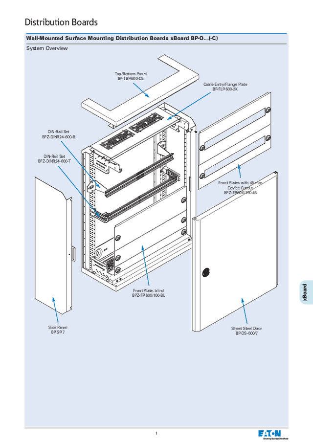
Wall-Mounted Surface Mounting Distribution Boards xBoard BP-O...(-C) System Overview Top/Bottom Panel BP-TBP-600-CE DIN-Rail Set BPZ-DINR24-600-B DIN-Rail Set BPZ-DINR24-600-T Side Panel BP-SP-7 Front Plate, blind BPZ-FP-600/100-BL Sheet Steel Door BP-DS-600/7 Front Plates with 45 mm Device Cutout BPZ-FP-600/150-45 Cable Entry/Flange Plate BP-FLP-600-2K Distribution Boards 1
Surface-Mounting Installation Distribution Boards, BP-O...(-C) (EW) • Modular design • Grounded metal covers • Flat-pack or fully assembled • Add-on options • Generous wiring space • Variable interior layout with/without removable mounting frame • Structured, multilayer construction for easy accessible installation: base frame - DIN-rails ... - enclosure • Reversible door hinging • Type BP-O-...-EW is equipped with a fireproof door (metal hinges and lock) Technical Data Electrical Design according to EN 60439-1/3, IEC 62208 Protection class I Degree of protection IP30 Rated voltage 415 VAC / 50Hz Rated current 630 A depending on the busbar support system Earth connections Base frame M5 earthing point screw Side wall, top/bottom panel M5 tapping screw Door M6 welding bolt Max. power loss (W) for all devices in the dist. board at 35° C ambi-ent temperature: Height \ Width (mm) 400 600 800 1000 1200 460 74 101 129 – – 760 104 137 156 – – 1060 133 147 203 264 – 1260 118 170 232 302 374 1560 144 207 281 364 429 Mechanical Material Sheet steel Paint coat Phosphatised and polyester-powder- coated Colour Grey RAL 7035, white RAL 9016 Door Doors with covered hinges, canbe unhinged at an angle ofmore than 90°Opening angle: 167 degrees (60° in case of several dist.boards mounted next to eachother) Door lock Hinged handle with rotary lock; cylinder lock; 3-point lock withclip down handle Cable entry Different covers permit cableentry from below and/or above Shock resistant IK07 Dimensions (mm) xbp_030-1-01a A1 50 B1 B2 50 C1 156,5 A2 185 C2 Distribution Boards 2 1) Door lock +8 mm 2) Number of hinge cut-outs for rotary handles. doors with clip down handle also available. 3) Number of locks for the right door. Left door contains two rotary handles in all dimensions. Type Outside dimensions Inside dimensions (front plate) Number of locks 2) Width Height Depth Width Height Depth A1 B1 C1 A2 B2 C2 Total 1) Without door BP-...-400/4 400 460 262,5 249 320 350 153 1 BP-...-400/7 400 760 262,5 249 320 650 153 1 BP-...-400/10 400 1060 262,5 249 320 950 153 1 BP-...-400/12 400 1260 262,5 249 320 1150 153 1 BP-...-400/15 400 1560 262,5 249 320 1450 153 1 BP-...-600/4 600 460 262,5 249 520 350 153 1 BP-...-600/7 600 760 262,5 249 520 650 153 1 BP-...-600/10 600 1060 262,5 249 520 950 153 1 BP-...-600/12 600 1260 262,5 249 520 1150 153 1 BP-...-600/15 600 1560 262,5 249 520 1450 153 1 BP-...-800/4 800 460 262,5 249 720 350 153 1 BP-...-800/7 800 760 262,5 249 720 650 153 1 BP-...-800/10 800 1060 262,5 249 720 950 153 1 BP-...-800/12 800 1260 262,5 249 720 1150 153 1 BP-...-800/15 800 1560 262,5 249 720 1450 153 1 BP-...-1000/10 1000 1060 262,5 249 920 950 153 1 3) BP-...-1000/12 1000 1260 262,5 249 920 1150 153 1 3) BP-...-1000/15 1000 1560 262,5 249 920 1450 153 1 3) BP-...-1200/12 1200 1260 262,5 249 1120 1150 153 1 3) BP-...-1200/15 1200 1560 262,5 249 1120 1450 153 1 3)
Surface-mounting distribution boards Profi Plus IP30 - components Base frames, BP-MF • Add-on design • Symmetrical layout • Consistent system perforation pattern (25 mm grid) • Material: sheet steel, zinc-coated thickness 1 mm • Scope of delivery: 1 base frame, 4 towers, fixing material Width [mm] A Height [mm] B 400 173 460 342,5 600 373 760 642,5 800 573 1060 942,5 1000 773 1260 1142,5 1200 973 1560 1442,5 Lower screws screwed into the first inner opening xbp_006-01a xbp_030-1-03 A 25 B Distribution Boards 3
Top / bottom panels, BP-TBP • The top/bottom panels are used as covers for the cabinet • With or without cable entry cutout • Material: sheet steel, powder-coated, RAL 7035 or RAL 9016 thickness 1 mm • Scope of delivery: 1 top panel, 1 bottom panel, fixing material Cable entry / flange plates, BP-FLP • Blind plate for closing the cable entry • Cable entry plate with pass-through flange 2K (pre-fitted) • Cable entry plate designed for F3A flange • Mounting into BP-TBP-...-CE panels • Can be used also for floor-standing board IP30 • Material: sheet steel, powder-coated, RAL 7035 thickness 1 mm • Scope of delivery: 1 cable entry/flange plate, fixing material xbp_030-1-04a xbp_030-1-05a xbp_030-1-06a BP-FLP-...-2K BP-FLP-...-F3A A2 A1 48,5 48,5 156,5 A1 A2 195 195 A3 28,5 C1 64 A1 A2 200 200 A3 27,5 C1 110 Dimensions [mm] Type Without cutout With cutout Depth Outside Inside Outside Inside width width width width A1 A2 A1 A2 BP-TBP-400 249 400 – 400 300 BP-TBP-600 249 600 – 600 500 BP-TBP-800 249 800 – 800 700 BP-TBP-1000 249 1000 – 1000 900 BP-TBP-1200 249 1200 – 1200 1100 Dimensions [mm] Type A1 A2 A3 C1 Number of flanges BP-FLP-400-BL 300 – – 155 - BP-FLP-400-2K 300 – 51,95 155 1 BP-FLP-600-BL 500 – – 155 - BP-FLP-600-2K 500 18 45,45 155 2 BP-FLP-800-BL 700 – – 155 - BP-FLP-800-2K 700 18 38,95 155 3 BP-FLP-1000-BL 900 – – 155 - BP-FLP-1000-2K 900 18 31,45 155 4 BP-FLP-1200-BL 1100 – – 155 - BP-FLP-1200-2K 1100 18 25,95 155 5 Type A1 A2 A3 C1 Number of openings for F3A flanges BP-FLP-400-F3A 300 – 44,45 155 1 BP-FLP-600-F3A 500 40 19,45 155 2 BP-FLP-800-F3A 700 22 12,45 155 3 BP-FLP-1000-F3A 900 11,33 12,45 155 4 BP-FLP-1200-F3A 1100 6 12,45 155 5 F3A 4 Distribution Boards
5 Distribution Boards Insertion Flanges F3A Pass-through Flange, ZSD-2K/FLA • Scope of delivery: 1 Flange Mas_ZSD_FLA 14x Ø 11 mm 8x Ø 15 mm 2x Ø 28 mm F3A-0 Blind flange VT17407 F3A-4 4xM16, 6xM25/16, 8xM32/20 VT17507 F3A-8 2xM20, 8xM25/16, 4xM32/20, 1xM50/32 VT17307 F3A-12 2xM16, 12xM20, 2xM40/25, 2xM50/32 VT17607 F3A-34 24xM16, 13xM20 VT17707 F3A-KTD 2 grommets for cables up to Ø 70 mm VT17807 F3A-D Cellular rubber pass-through flange, 40 cables Ø 10-13 mm, 4 cables Ø 17-21 mm, 2 cables Ø 27-30 mm VT17207 Shift-back Flange, PB-FLP-...-VS VT13208
Side panels BP-SP, BPZ-SP-MSW • Side panels are used as part of cover for the cabinet • 2 variants (for mounting with / without BPZ-MSW) • Material: sheet steel, powder-coated, RAL 7035 or RAL 9016 thickness 1 mm • Scope of delivery: 2 side panels Mounting of front plates BPZ-FP into side panels BP-SP BP-SP: a bend for mounting of front plates, it is not possible to combine with side walls BPZ-MSW. BPZ-SP-MSW: without the bend, mounting of front plates onto side walls BPZ-MSW. BP-SP: a bend for mounting of front plates, it is not possible to combine with side walls BPZ-MSW BPZ-SP-MSW: without the bend, mounting of front plates onto side walls BPZ-MSW. For front plates mounting, also BPZ-FPS can be used in case that BPZ-MSW is not used xbp_007-0-00 xbp_007-0-01 xbp_007-1-00 xbp_007-1-01 6 Distribution Boards
7 Distribution Boards Assembling of surface-mounted board IP30 Board without a possibility of installation of mounting frame BPZ-MSW BP-TBP-...-CE BP-FLP-...-2K(3 variants) BP-SP-...(without a possibility to use BPZ-MSW) BP-MF-... BP-TBP-...(2 variants) Without side wall BPZ-MSW À xbp_008-0-00 xbp_008-0-01 xbp_008-0-02 Mounting process: 1. Mounting of towers BPZ-CTS-L onto base frame BP-MF. Towers BPZ-CTS-L are in a scope of delivery of the frame BP-MF. Detail
Á Â Ä ? ? ? xbp_008-0-03 xbp_008-0-04 xbp_008-0-05 xbp_008-0-06 2. Assembly of cable entry plates BP-FLP onto towers BPZ-CTS-L 3. Assembly of top / bottom panel without cutout (if used) 4. Fixing of top / bottom panel without cutout into towers BPZ-CTS-L by means of screws 5. Addition of cable entry plate with top / bottom panel 6. Fixing of top / bottom panel with cutout into towers BPZ-CTS-L by means of screws 7. Assembly of side panels BP-SP 8. Fixing of side panels BP-SP Ç xbp_008-0-07 xbp_008-0-08 Detail Detail 8 Distribution Boards
9 Distribution Boards Assembling of surface-mounted board IP30 Board for installation of mounting frame BPZ-MSW BP-TBP-...-CE BP-FLP-...-2K(3 variants) BPZ-SP-...-MSW(intended for use with BPZ-MSW) BP-MF-... BP-TBP-...(2 variants) With side wall BPZ-MSW À BPZ-MSW-... xbp_008-1-00 xbp_008-0-01 xbp_008-0-02 Mounting process: 1. Mounting of towers BPZ-CTS-L onto base frame BP-MF. Towers BPZ-CTS-L are in a scope of delivery of the frame BP-MF. 2. Pre-screwing of a screw which creates bottom hitch for frame BPZ-MSW. Detail Á xbp_008-1-01 xbp_008-1-02 Detail
à  xbp_008-1-03 xbp_008-1-04 3. Placing of the frame from side walls BPZ-MSW on bottom hitch 4. Tipping of the side walls BPZ-MSW to correct position 5. Fixing of the frame with top hitch screw 6. Assembly of cable entry plates BP-FLP onto towers BPZ-CTS-L 7. Assembly of top / bottom panel without cutout (if used) 8. Fixing of top / bottom panel without cutout into towers BPZ-CTS-L by means of screws 9. Addition of cable entry plate with top / bottom panel 10. Fixing of top / bottom panel with cutout into towers BPZ-CTS-L by means of screws 11. Assembly of side panels BPZ-SP-MSW 12. Fixing of side panels BPZ-SP-MSW xbp_008-1-06 È Ç Detail xbp_008-1-07 11 È 1. 2. 2. 1. Ä xbp_008-1-05 Å Æ xbp_008-1-08 M6 x 12 12 10 Distribution Boards
11 Distribution Boards BPZ-DINR...(mounting directlyonto rear frame,max. depth) BPZ-DINR...-T(mounting onto towerwith adjustable depth) BPZ-DINR...-B(mounting onto towerwith fixed depth) BPZ-DINR... + BEL...(mounting onto sidewalls BPZ-MSW) possi-ble only of side panels BPZ-SP-MSW are used xbp_010-00 xbp_010-01 Zero position for mounting of front plates • Defines lower edge of the first bottom front plate - first step of assembly • For standard front plate height 150 mm, the center of the first bottom device rail is located 75 mm above the zero position Zero position for mounting of device rails and front plates(the second opening from the bottom)Defines lower edge of bottom front plate xbp_009-00a xbp_009-01a Mounting of device rails 25 150 150 150 75 75 I. Rear mounting onto base frame II. Mounting onto side walls BPZ-MSW Detail
xbp_030-1-9a 30 8 xbp_012-0-00 Detail 1 Detail 2 Mounting of door BP-DS Mounting process: 1. Mounting of lug for lock rod on the respective side (in scope of delivery of side panels) 2. Inserting of door at the opening angle about 90° 3. Inserting of hinge pins 4. Fixing of the pins in plastic bracket À xbp_012-0-01 xbp_012-0-02 Â Ã xbp_012-1-01 xbp_012-1-02 xbp_012-1-03 Detail 1 Detail 2 Á Sheet steel doors, BP-DS • Front-mounted • Quick mounting and removing of the door • Right or left hinged • Opening angle 167° • 1-point lock through rotary lock, 3-point lock with clip down handle • Material: sheet steel, powder-coated, RAL 7035 thickness 1 mm • Scope of delivery: 1 door, set for earth connection Transparent doors (sheet steel), BP-DT • Material: 2 mm of plexiglas 30 8 xbp_030-1-10a BP-DS BP-DT 12 Distribution Boards
13 Distribution Boards xbp_021-1-01 xbp_021-1-04 Horizontal/middle add-on connection element, BP-MFL • For mounting distribution boards one on top of the other • For surface mounting boards IP30 • Possible to combine with BP-MSL for cross combination of boards • Material: sheet steel, powder-coated, RAL 7035 • Scope of delivery: 1 horizontal/middle add-on connection element, 2 mounting elements, fixing material Mounting process: • For a pair of boards, only one set of top / bottom panels is used 1. Placing of base frames BP-MF to correct possition 2. Remove of screws of towers BPZ-CTS-L at sides near to boards connection 3. Put of mounting elements on the loosened screws 4. Tightening of fixing screws 5. Assembly of connection element 6. Fixing of connection element 7. Mounting of top and bottom panels BP-TBP 8. Mounting of side walls BP-SP, BPZ-SP-MSW 9. Mounting of doors BP-DS Detail xbp_021-1-07 xbp_021-1-13
xbp_021-0-18 Ä xbp_021-0-06 Â Ã xbp_021-0-11 Å Vertical/middle add-on connection element, BP-MSL • For mounting distribution boards one next to the other (in parallel) • Possible to combine with BP-MFL for cross combination of boards • Material: sheet steel, powder-coated, RAL 7035 • Scope of delivery: 1 vertical/middle add-on connection element, 2 mounting elements, fixing material Mounting process: • The process is identical for both BP-MSL and BP-MSL-MSW • For a pair of boards, only one set of side panels BP-SP, BPZ-SP-MSW is used 1. Placing of base frames BP-MF to correct possition, pre-screwing of fixing screws 2. Put of mounting elements and fixing of screws 3. Mounting of towers BPZ-CTS-L onto base frame BP-MF. Towers BPZ-CTS-L are in a scope of delivery of the frame BP-MF. 4. Mounting of top and bottom panels BP-TBP and pre-screwing of add-on connection element screws. Assembly of add-on element 5. Connected pair of boards. Mounting of lugs for locks rods 6. Mounting of doors To preserve maximum opening angle, both boards have to have oposite direction of door opening xbp_021-0-01 À xbp_021-0-03 Á xbp_021-0-14 Separation panel, BPZ-ASB • Internal vertical separation between two sections • Fixing on the rear frame • Painted, grey RAL 7035 03 14 Distribution Boards
15 Distribution Boards Surface-Mounting Installation Distribution Boards BPM-O... • Excellent stability due to welded construction • Grounded metal covers • Generous wiring space • Variable interior layout with/without removable mounting frame • Structured, multilayer construction for easy accessible installation • Reversible door hinging Technical Data Electrical Design according to EN 60439-1/3, IEC 62208 Protection class I Degree of protection IP54 Rated voltage 415 VAC / 50Hz Rated current 630 A depending on the busbar support system Earth connections Base frame M8 welding bolt Door M6 welding bolt Max. power loss (W) for all devices in the dist. board at 35° C ambi-ent temperature: Height \ Width (mm) 400 600 800 1000 1200 460 76 105 134 – – 760 106 140 161 – – 1060 137 150 209 269 – 1260 121 174 239 308 386 1560 149 212 289 372 435 Mechanical Material Sheet steel Paint coat Phosphatised and polyester-powder- coated Colour Grey RAL 7035 Door Doors with covered hinges,Opening angle: 100 degrees Door lock Two-way key bit; 3-point lockwith clip down handle Cable entry Open cable entry, prepared forF3A-Flanges Shock resistant IK07 xbp_030-1-08a A1 40 58,5 120 C1 A2 C2 B2 B1 210 A4 Dimensions (mm) Type Outside dimensions Inside dimensions Mounting brackets Cable Amount of F3A Number of (front plate) - openings distance cutout flanges locks 1) Width Height Depth Width Height Depth Width Height A1 B1 C1 A2 B2 C2 A3 B3 A4 BPM-O-400/4 400 460 270 320 350 155 340 500 94 1 1 BPM-O-400/7 400 760 270 320 650 155 340 800 94 1 2 BPM-O-400/10 400 1060 270 320 950 155 340 1100 94 1 3 BPM-O-400/12 400 1260 270 320 1150 155 340 1300 94 1 3 BPM-O-400/15 400 1560 270 320 1450 155 340 1600 94 1 3 BPM-O-600/4 600 460 270 520 350 155 540 500 69 2 1 BPM-O-600/7 600 760 270 520 650 155 540 800 69 2 2 BPM-O-600/10 600 1060 270 520 950 155 540 1100 69 2 3 BPM-O-600/12 600 1260 270 520 1150 155 540 1300 69 2 3 BPM-O-600/15 600 1560 270 520 1450 155 540 1600 69 2 3 BPM-O-800/4 800 460 270 720 350 155 740 500 44 3 1 BPM-O-800/7 800 760 270 720 650 155 740 800 44 3 2 BPM-O-800/10 800 1060 270 720 950 155 740 1100 44 3 3 BPM-O-800/12 800 1260 270 720 1150 155 740 1300 44 3 3 BPM-O-800/15 800 1560 270 720 1450 155 740 1600 44 3 3 BPM-O-1000/10 1000 1060 270 920 950 155 940 1100 144 3 3 2) BPM-O-1000/12 1000 1260 270 920 1150 155 940 1300 144 3 3 2) BPM-O-1000/15 1000 1560 270 920 1450 155 940 1600 144 3 3 2) BPM-O-1200/12 1200 1260 270 1120 1150 155 1140 1300 119 4 3 2) BPM-O-1200/15 1200 1560 270 1120 1450 155 1140 1600 119 4 3 2) 1) Number of hinge cut-outs for rotary handles. doors with clip down handle also availa-ble. 2) Number of locks for the right door. Left door contains two rotary handles in all dimen-sions. 3) Number of cut outs for F3A flanges on the top.
WFB-SET-CSWall angle brackets (must be ordered separetely) F3A-...Cable flanges (must be ordered separately) BPZ-FPS...Front plate support BPZ-DINR...Device rails mounted with towers onto rear frame BPZ-FP-...Front plate BPM-O-...Surface mounted board with door, IP54 xbp_013-0-02 Mounting of device rails onto rear frame (without mounting frame BPZ-MSW) • Front plates are mounted onto supports BPZ-FPS (not in scope of delivery of BPM-O board) • Welded construction, side panels of the cover cannot be unmounted Distribution Boards 16
Mounting of device rails with mounting frame BPZ-MSW • Mounting onto corner towers BPZ-CTS-L (not in scope of delivery of BPM-O board) • The mounting process of side walls BPZ-MSW is identical with version IP30 • Front plates are mounted directly onto BPZ-MSW • Welded construction, side panels of the cover cannot be unmounted BPZ-CTS-LTower for mounting of sidewall BPZ-MSW. Can also beused for mounting of N/PE ter-minals holder. BPZ-MSW...Mounting sidewalls WFB-SET-CS(wall angle brackets) F3A-...Cable flanges BPM-O-...Surface mounted board withdoor, IP54 BPZ-MSW...Mounting side walls BPZ-DINR...Device rails ... mounted onto side walls BPZ-CTS-LCorner tower for mount-ing of side walls BPZ-MSW. Can also be used for mounting of N/PE terminals holder. BPZ-FP-...Front plate xbp_013-0-04 xbp_013-0-03 Distribution Boards 17
18 Distribution Boards Wall-Mounted Flush-mounting Distribution Boards xBoard - 2-Step-System BP-U...(-C) System Overview Top/Bottom Panel for Wall Box BPZ-WB2STBP-600/2 Wall Box BPZ-WBO2S-600/7/2 DIN-Rail + Fastening Element BPZ-DINR24-600 + BEL Front Plate, blind BPZ-FP-600/050-BL Front Plates with 45 mm Device Cutout BPZ-FP-600/150-45 Flush-Mounting Door Frame with Door BP-U-600/7 Mounting Side Wall BPZ-MSW-7
19 Distribution Boards Flush-Mounting Installation Distribution Boards - 2-Step-System BP-U...(-C) • Grounded metal covers • Generous wiring space • Variable interior layout with removable mounting frame • Structured, multilayer construction for easy accessible installation: mounting sied wall - DIN-rails ... - enclosure • Reversible door hinging Technical Data Electrical Design according to EN 60439-1/3, IEC 62208 Protection class I Degree of protection IP30 Rated voltage 415 VAC / 50Hz Rated current 630 A depending on the busbar support system Earth connections Base frame M5 earthing point screw Door M6 welding bolt Max. power loss (W) for all devices in the dist. board at 35°C ambi-ent temperature:BP-U-.../1 Height \ Width (mm) 320 520 720 920 1120 350 35 53 – – – 650 54 80 106 – – 950 73 106 139 150 – 1150 86 124 131 177 222 1450 – 107 162 218 283 BP-U-.../2 Height \ Width (mm) 320 520 720 920 1120 350 38 59 – – – 650 60 86 114 – – 950 82 115 129 167 – 1150 95 133 146 197 256 1450 – 126 180 247 320 Mechanical Material Sheet steel Paint coat Phosphatised and polyester-powder-coated Colour Grey RAL 7035 Door Flush doors with coveredhinges, can be unhinged at anangle of more than 90°Opening angle: 110 degrees Door lock Hinged handle with rotary lock;cylinder lock; 3-point lock withclip down handle Shock resistant IK07 Dimensions (mm) B a A C c 93 7 d b e MU A a B b C c d e Outside Front- Outside Inside Outside Installation Installation Installation height plate width width depth depth height width height BP-U-600/7-C 96 700 650 600 520 247 240 685 555 BP-U-600/10-C 144 1000 950 600 520 247 240 985 555 BP-U-600/12-C 168 1200 1150 600 520 247 240 1185 555 BP-U-600/15-C 216 1500 1450 600 520 247 240 1485 555 BP-U-800/7-C 140 700 650 800 720 247 240 685 755 BP-U-800/10-C 210 1000 950 800 720 247 240 985 755 BP-U-800/12-C 245 1200 1150 800 720 247 240 1185 755 BP-U-800/15-C 315 1500 1450 800 720 247 240 1485 755
20 Distribution Boards Flush-Mounting Installation Distribution Boards - 2-Step System Wall Box - Open for 2-Step System, BPZ-WBO2S • Depth 1 = 180 mm or Depth 2 = 240 mm • Easy-to-remove relief stamp • Suitable for installation of the 2-step flush-mounting door frame • Material: Sheet steel, zinc-coated • Scope of delivery: 1 Wall box, fixing material B 25 54 147 177 177 A a 17 87 B A • Dimensions (mm) A B a A B a Outside height Outside width Distance Outside height Outside width Distance BPZ-WBO2S-400/4/1 380 323 – BPZ-WBO2S-800/7/1 680 723 – BPZ-WBO2S-400/4/2 380 323 – BPZ-WBO2S-800/7/2 680 723 286 BPZ-WBO2S-400/7/1 680 323 – BPZ-WBO2S-800/10/1 980 723 – BPZ-WBO2S-400/7/2 680 323 286 BPZ-WBO2S-800/10/2 980 723 586 BPZ-WBO2S-400/10/1 980 323 – BPZ-WBO2S-800/12/1 1180 723 – BPZ-WBO2S-400/10/2 980 323 586 BPZ-WBO2S-800/12/2 1180 723 786 BPZ-WBO2S-400/12/1 1180 323 – BPZ-WBO2S-800/15/1 1480 723 – BPZ-WBO2S-400/12/2 1180 323 786 BPZ-WBO2S-800/15/2 1480 723 1086 BPZ-WBO2S-600/4/1 380 523 – BPZ-WBO2S-1000/10/1 980 923 – BPZ-WBO2S-600/4/2 380 523 – BPZ-WBO2S-1000/10/2 980 923 586 BPZ-WBO2S-600/7/1 680 523 – BPZ-WBO2S-1000/12/1 1180 923 – BPZ-WBO2S-600/7/2 680 523 286 BPZ-WBO2S-1000/12/2 1180 923 786 BPZ-WBO2S-600/10/1 980 523 – BPZ-WBO2S-1000/15/1 1480 923 – BPZ-WBO2S-600/10/2 980 523 586 BPZ-WBO2S-1000/15/2 1480 923 1086 BPZ-WBO2S-600/12/1 1180 523 – BPZ-WBO2S-1200/12/1 1180 1123 – BPZ-WBO2S-600/12/2 1180 523 786 BPZ-WBO2S-1200/12/2 1180 1123 786 BPZ-WBO2S-600/15/1 1480 523 – BPZ-WBO2S-1200/15/1 1480 1123 – BPZ-WBO2S-600/15/2 1480 523 1086 BPZ-WBO2S-1200/15/2 1480 1123 1086 Top/Bottom Panel for 2-Step System Wall Box, Depth 2 (240 mm), BPZ-WB2STBP • Only for depth 2 • Blind (without cutout) or with cutout for cable entry • Easy-to-remove relief stamp • Suitable for installation on open wall box • Material: Sheet steel, zinc-coated • Scope of delivery: 1 Top/bottom panel, fixing material 23 8 A 68 37 195 c b 195 a • Dimensions (mm) A a b c Outside Outside Distance Distance Distance width depth BPZ-WB2STBP-400/2 329 238 67 – 67 BPZ-WB2STBP-600/2 529 238 25.5 88 25.5 BPZ-WB2STBP-800/2 729 238 25.5 2x 46.5 25.5 BPZ-WB2STBP-1000/2 929 238 25.5 2x 32.67 25.5 BPZ-WB2STBP-1200/2 1129 238 25.5 2x 25.75 25.5 Depth 2 Depth 1
21 Distribution Boards 2-Step Flush-Mounting Door Frame, with Door, BP-U • Material: Sheet steel, powder-coated, RAL 7035 • Scope of delivery: Frame, door with hinges, rotary lock, fixing material for BPZ-MSW mounting side wall 93 c A 91 B 91 25 11 7 • Dimensions (mm) A B c Outside Outside Inside width height width BP-U-400/4 400 400 353 BP-U-400/7 400 700 353 BP-U-400/10 400 1000 353 BP-U-400/12 400 1200 353 BP-U-600/4 600 400 553 BP-U-600/7 600 700 553 BP-U-600/10 600 1000 553 BP-U-600/12 600 1200 553 BP-U-600/15 600 1500 553 BP-U-800/7 800 700 753 BP-U-800/10 800 1000 753 BP-U-800/12 800 1200 753 BP-U-800/15 800 1500 753 BP-U-1000/10 1000 1000 953 BP-U-1000/12 1000 1200 953 BP-U-1000/15 1000 1500 953 BP-U-1200/12 1200 1200 1153 BP-U-1200/15 1200 1500 1153 Mounting Side Wall, BPZ-MSW • Suitable for installation on the 2-step flush-mounting door frame with door • Material: Sheet steel, zinc-coated • Scope of delivery: 2 Mounting side walls • Dimensions (mm) A B Outside Inside Outside Frontplate height height depth height BPZ-MSW-4 330 293 117 350 BPZ-MSW-7 630 593 117 650 BPZ-MSW-10 930 893 117 950 BPZ-MSW-12 1130 1093 117 1150 BPZ-MSW-15 1430 1393 117 1450 BPZ-MSW-17 1630 1593 117 1650 BPZ-MSW-20 1930 1893 117 1950 12 5x 12 B 25 25 A Pos. 1 36 17 7 Pos. 2 14 1 36
Wall-Mounted Flush-mounting Distribution Boards xBoard - 3-Step-System System Overview 22 Distribution Boards Rear Wall BPZ-RP-600/7 Wall Box consists of Side Panel, Top/Bottom BPZ-WB3S-600/7/2 Front Plate blind BPZ-FP-600/050-BL Flush-Mounting Door Framewith Door BP-U-3S-600/7 Mounting Side Wall BPZ-MSW-7/SNAP DIN-Rail + Fastening Element BPZ-DINR24-600 + BEL Front Plate with 45 mm Device Cut-outBPZ-FP-600/150-45
23 Distribution Boards Flush-Mounting Installation Distribution Boards - 3-Step-System BP.-U-3S... • Grounded metal covers • Generous wiring space • Variable interior layout with removable mounting frame • Structured, multilayer construction for easy accessible installation: mounting sied wall - DIN-rails ... - enclosure • Reversible door hinging • Levelling possible to offset surface unevenness of up to 18 mm Technical Data Electrical Design according to EN 60439-1/3, IEC 62208 Protection class I Degree of protection IP30, IP43, IP54 Rated voltage 415 VAC / 50Hz Rated current 630 A depending on the busbar support system Earth connections Base frame M5 earthing point screw Door M6 welding bolt Max. power loss (W) for all devices in the dist. board at 35°C ambi-ent temperature:BP.-U-3S-.../1 Height \ Width (mm) 330 530 730 930 1130 350 37 56 – – – 650 57 82 110 – – 950 77 109 142 142 – 1150 90 128 127 163 220 1450 – 109 150 227 278 1650 – 116 174 247 316 1950 – 131 215 288 372 BP.-U-3S-.../2 Height \ Width (mm) 330 530 730 930 1130 350 41 81 – – – 650 63 90 118 – – 950 85 118 129 160 – 1150 99 136 140 187 264 1450 – 122 171 248 309 1650 – 134 203 274 354 1950 – 157 241 325 402 Mechanical Material Sheet steel, Aluminium (IP43, IP54) Paint coat Phosphatised and polyester-powder-coated Colour Grey RAL 7035, white RAL 9016 Door Flush doors with coveredhinges, can be unhinged at anangle of more than 90°Opening angle: 110 degrees Door lock Hinged handle with rotary lock;cylinder lock; 3-point lock withclip down handle,Two-way key bit Shock resistant IK07 Flush-Mounting Installation Distribution Boards - 3-Step System Wall Box - for 3-Step System, BPZ-WB3S • Depth 1 = 180 mm or Depth 2 = 240 mm • Easy-to-remove relief stamp • Suitable for installation of the 3-step flush- mounting door frame • Material: Sheet steel, zinc-coated • Scope of delivery: 1 Wall box, fixing material Cable entry above Cable entry side xbp_003-00
Type Outside dimensions Inside dimensions Embrasure (front plate) (installation dimensions) Width Height Depth Width Height Depth Width Height Depth A1 B1 C1 A2 B2 C2 A3 B3 C3 ...400/4.. 435 460 247 / 187 320 350 182 / 122 410 435 240 / 180 ...400/7.. 435 760 247 / 187 320 650 182 / 122 410 735 240 / 180 ...400/10.. 435 1060 247 / 187 320 950 182 / 122 410 1035 240 / 180 ...400/12.. 435 1260 247 / 187 320 1150 182 / 122 410 1235 240 / 180 ...600/4.. 635 460 247 / 187 520 350 182 / 122 610 435 240 / 180 ...600/7.. 635 760 247 / 187 520 650 182 / 122 610 735 240 / 180 ...600/10.. 635 1060 247 / 187 520 950 182 / 122 610 1035 240 / 180 ...600/12.. 635 1260 247 / 187 520 1150 182 / 122 610 1235 240 / 180 ...600/15.. 635 1560 247 / 187 520 1450 182 / 122 610 1535 240 / 180 ...600/17.. 635 1760 247 / 187 520 1650 182 / 122 610 1735 240 / 180 ...600/20.. 635 2060 247 / 187 520 1950 182 / 122 610 2035 240 / 180 ...800/7.. 835 760 247 / 187 720 650 182 / 122 810 735 240 / 180 ...800/10.. 835 1060 247 / 187 720 950 182 / 122 810 1035 240 / 180 ...800/12.. 835 1260 247 / 187 720 1150 182 / 122 810 1235 240 / 180 ...800/15.. 835 1560 247 / 187 720 1450 182 / 122 810 1535 240 / 180 ...800/17.. 835 1760 247 / 187 720 1650 182 / 122 810 1735 240 / 180 ...800/20.. 835 2060 247 / 187 720 1950 182 / 122 810 2035 240 / 180 ...1000/10.. 1035 1060 247 / 187 920 950 182 / 122 1010 1035 240 / 180 ...1000/12.. 1035 1260 247 / 187 920 1150 182 / 122 1010 1235 240 / 180 ...1000/15.. 1035 1560 247 / 187 920 1450 182 / 122 1010 1535 240 / 180 ...1000/17.. 1035 1760 247 / 187 920 1650 182 / 122 1010 1735 240 / 180 ...1000/20.. 1035 2060 247 / 187 920 1950 182 / 122 1010 2035 240 / 180 ...1200/12.. 1235 1260 247 / 187 1120 1150 182 / 122 1210 1235 240 / 180 ...1200/15.. 1235 1560 247 / 187 1120 1450 182 / 122 1210 1535 240 / 180 ...1200/17.. 1235 1760 247 / 187 1120 1650 182 / 122 1210 1735 240 / 180 ...1200/20.. 1235 2060 247 / 187 1120 1950 182 / 122 1210 2035 240 / 180 xbp_030-0-01a A3 A1 C3 C1 C2 B2 A2 B3 7 B1 Dimensions (mm) Distribution Boards 24
Top and bottom panel of wall box BPZ-WB3S Depth 180, 240 Width 400 Width 4600 Width 800 Width 1000 Width 1200 xbp_003-03a 189 x 81 12,5 101 187 101 202 303 404 181 404 183 303 185 202 Side panels of wall box BPZ-WB3S Depth 180, 240 Height 2060 Height 1760 Height 1560 Height 1260 Height 1060 Height 760 Height 460 xbp_003-01a 303 303 1212 303 303 912 202 914 202 202 614 202 414 202 202 202 202 114 202 x 13,5 86 a) for 180 mm x = 180 mmb) for 240 mm x = 180 mm a) for 180 mm x = 179 mmb) for 240 mm x = 239 mm Distribution Boards 25
Connecting of flush-mounting boards with BPZ-BR/WB3S • Use of coupling flange BPZ-BR/WB3S • The coupling flanges define respective space in between particular wall boxes • Possible to connect boards in parallel, one above the other or into a cross (i.e. parallel and one above the other at the same time) The big opening toward the rear Connection of boards in parallel / above the other Cross connection of 4 boards (2 x 2) xbp_004-00 xbp_004-01 xbp_004-02 Mounting process: 1. Placing of wall boxes BPZ-WB3S in prallel / one above the other 2. Put of flange BPZ-BR/WB3S. The big opening has to be oriented toward the rear 3. Fixing of the flange by means of screws + Distribution Boards 26
Mounting of side walls BPZ-MSW into wall box BPZ-WB3S Mounting process: 1. Placing of the side wall BPZ-MSW on bottom hitch 2. Tipping of the side wall to correct position. This position is indicated with click of the pawl BPZ-SNAP. 3. Tightening of the top hitch screw 4. Tightening of the bottom hitch screw Notes: • Usually, a complete frame (2 side walls, device rails, devices) is mounted • For flush-mounting boards, the sidewalls BPZ-MSW have to be equipped with pawls BPZ-SNAP. These pawls do not substitute a function of the original screw. The frame has to be fixed with this screw! • To demount the frame BPZ-MSW, a flat screwdriver is necessary to press away a pin of pawl BPZ-SNAP. Top hitch (initial position) Bottom hitch – screw (in initial position) xbp_005-1-00 xbp_005-1-00a xbp_005-1-00b xbp_005-0-00 xbp_005-0-01 Detail of bottom hitch ) possibility of change of side wall depth Detail of top hitch xbp_005-1-03 xbp_005-1-04 Á À Â, Ã BPZ-SNAP Mounting process for pawl BPZ-SNAP: ) ) BPZ-MSW Distribution Boards 27
28 Distribution Boards Rear walls, BPZ-RP BPZ-WB3S BPZ-RP, BPZ-RPP xbp_005-3-00 • Rear wall for wall box BPZ-WB3S • Material: sheet steel, zinc-coated, thickness 1 mm, plastic • Mounting by means of self-sealing tape • Scope of delivery: 1 rear panel • Attention: sheet steel rear wall must be connected through screws into the earthing concept!
29 Distribution Boards 3-Step Flush-Mounting Door Frame, with Door, BP.-U-3S-... • IP30 . . . BP-U-3S • IP43 . . . BPA-U-3S, with foamed sealing and rain bar for outdoor application • IP54 . . . BPM-U-3S, with foamed sealing for moisture-proof application • Material: Sheet steel, powder-coated, RAL 7035 or RAL 9016 Aluminium, powder-coated, RAL 7035 • Scope of delivery: Frame, door with hinges xbp_030-0-05 xbp_030-0-02a A1 B2 B1 A2 Dimensions [mm] Type Outside dimensions Inside dimensions Number of locks 1) Width Height Width Height IP30 IP43 A1 B1 A2 B2 IP54 BP.-U-3S-400/4... 435 460 330 360 1 1 BP.-U-3S-400/7... 435 760 330 660 1 2 BP.-U-3S-400/10... 435 1060 330 960 1 2 BP.-U-3S-400/12... 435 1260 330 1160 2 2 BP.-U-3S-600/4... 635 460 530 360 1 1 BP.-U-3S-600/7... 635 760 530 660 1 2 BP.-U-3S-600/10... 635 1060 530 960 1 2 BP.-U-3S-600/12... 635 1260 530 1160 2 2 BP.-U-3S-600/15... 635 1560 530 1460 2 3 BP.-U-3S-600/17... 635 1760 530 1660 3 3 BP.-U-3S-600/20... 635 2060 530 1960 3 3 BP.-U-3S-800/7... 835 760 730 660 1 2 BP.-U-3S-800/10... 835 1060 730 960 1 2 BP.-U-3S-800/12... 835 1260 730 1160 2 2 BP.-U-3S-800/15... 835 1560 730 1460 2 3 BP.-U-3S-800/17... 835 1760 730 1660 3 3 BP.-U-3S-800/20... 835 2060 730 1960 3 3 BP.-U-3S-1000/10... 1035 1060 930 960 1 2) 2 2) BP.-U-3S-1000/12... 1035 1260 930 1160 2 2) 2 2) BP.-U-3S-1000/15... 1035 1560 930 1460 2 2) 3 2) BP.-U-3S-1000/17... 1035 1760 930 1660 3 2) 3 2) BP.-U-3S-1000/20... 1035 2060 930 1960 3 2) 3 2) BP.-U-3S-1200/12... 1235 1260 1130 1160 2 2) 2 2) BP.-U-3S-1200/15... 1235 1560 1130 1460 2 2) 3 2) BP.-U-3S-1200/17... 1235 1760 1130 1660 3 2) 3 2) BP.-U-3S-1200/20... 1235 2060 1130 1960 3 2) 3 2) 1) Number of hinge cut-outs for rotary handles. doors with clip down handle also available. 2) Number of locks for the right door. Left door contains two rotary handles in all dimensions.
30 Distribution Boards Separation Frame, BPZ-USF • Only for flush-mounting boards with a width of 1000 and 1200 mm • Only with MSW application • For segarate a 1000 or 1200 mm board in a 600/400 or 600/600 section • Material: Sheet steel, powder-coated grey (RAL 7035) and white (RAL 9016) • Scope of delivery: 1 Segaration Frame and fixing material
31 Distribution Boards Floor-Standing Distribution Board xBoard BP-F-... System Overview Corner Tower Set BPZ-CTS-L BPZ-CTS-S DIN-Rail Set BPZ-DINR24-600-B Corner Tower Set BPZ-CTS-S Sheet Steel Door BPZ-DS-600/20 Mounting Side Wall BPZ-MSW-12 Front Plates blind BPZ-FP-600/100-BL Front Plates with 45mm Device Cut-out BPZ-FP-600/150-45 Mounting Plate NZM BPZ-NZM3-600-MV Front Plate Support BPZ-FPS/8 Floor Standing Cabinet BP-F-600/20/3-F
xbp_030-2-01a A1 50 50 C1 173 B1 B2 A2 C2 32 Distribution Boards Floor-Standing Distribution Boards, BP-F-... • Grounded metal covers • Excellent stability thanks to the welded construction • Generous wiring space • Variable interior layout with/without removable mounting frame • Structured, multilayer construction for easy accessible installation: base frame - DIN-rails ... - enclosure • Reversible door hinging Technical Data Electrical Design according to EN 60439-1/3, IEC 62208 Protection class I Degree of protection IP30 Rated voltage 415 VAC / 50Hz Rated current 1200 A depending on the busbar support system Earth connections Base frame M8 welding bolt Door M6 welding bolt Max. power loss (W) for all devices in the dist. board at 35° C ambi-ent temperature: Height / Width (mm) 400 600 800 1000 1200 1760 179 258 347 420 478 2060 220 305 320 448 519 Mechanical Material Sheet steel Paint coat Phosphatised and polyester-powder- coated Colour Grey RAL 7035, white RAL 9016 Door Doors with covered hinges, canbe unhinged at an angle ofmore than 90°Opening angle: 167 degrees (60°in case of several dist. boards mounted next to each other) Door lock Hinged handle with rotary lock; cylinder lock; 3-point lock withclip down handle Cable entry Different covers permit cableentry from below and/or above Shock resistant IK07 Dimensions (mm) Type Outside dimensions Inside dimensions Pv Number of locks 1) Width Height Depth Width Height Depth W A1 B1 C1 A2 B2 C2 without door / with door BP-F-400/17/3 400 1760 286,5 / 300 320 1650 155 203 2 BP-F-400/20/3 400 2060 286,5 / 300 320 1950 155 225 2 BP-F-600/17/3 600 1760 286,5 / 300 520 1650 155 297 2 BP-F-600/20/3 600 2060 286,5 / 300 520 1950 155 343 2 BP-F-800/17/3 800 1760 286,5 / 300 720 1650 155 387 2 BP-F-800/20/3 800 2060 286,5 / 300 720 1950 155 415 2 BP-F-1000/17/3 1000 1760 286,5 / 300 920 1650 155 455 2 2) BP-F-1000/20/3 1000 2060 286,5 / 300 920 1950 155 511 2 2) BP-F-1200/17/3 1200 1760 286,5 / 300 1120 1650 155 545 2 2) BP-F-1200/20/3 1200 2060 286,5 / 300 1120 1950 155 561 2 2) BP-F-400/20/2,5 400 2060 236,5 / 250 320 1950 185 196 2 BP-F-600/20/2,5 600 2060 236,5 / 250 520 1950 185 316 2 BP-F-800/20/2,5 800 2060 236,5 / 250 720 1950 185 386 2 BP-F-1000/20/2,5 1000 2060 236,5 / 250 920 1950 185 468 2 2) BP-F-1200/20/2,5 1200 2060 236,5 / 250 1120 1950 185 535 2 2) BP-F-400/20/4 400 2060 386,5 / 400 320 1950 255 293 2 BP-F-600/20/4 600 2060 386,5 / 400 520 1950 255 388 2 BP-F-800/20/4 800 2060 386,5 / 400 720 1950 255 480 2 BP-F-1000/20/4 1000 2060 386,5 / 400 920 1950 255 556 2 2) BP-F-1200/20/4 1200 2060 386,5 / 400 1120 1950 255 624 2 2) no assembly spar (only MSW construction) 1) Number of hinge cut-outs for rotary handles. doors with clip down handle also available. 2) Number of locks for the right door. Left door contains two rotary handles in all dimensions.
33 Distribution Boards Change of clip down handle for change of direction of opening of door xbp_032-00-01 xbp_032-0-02 1. Demounting of rods – removing from lock mechanism 2. Demounting of rods – taking out from fastening lugs À À Á Á A B A B Detail: Before xbp_032-0-09 A B Detail: After Sheet Steel Doors, BPZ-DS • Front-mounted • Quick mounting and removing of the door • Right or left hinged • Opening angle 167° • 1-point lock through rotary lock, 3-point lock through clip-down handle • Material: Sheet steel, powder-coated, RAL 7035 or RAL 9016 • Weight (kg): Width (mm) 400 600 800 600+400 600+600 Height 1700 6,2 9 11,8 9+6,5 9+9,1 Height 2000 7,3 10,6 13,8 10,6+7,7 10,6+10,6 • Scope of delivery: 1 Door 30 8 167° 90 8 110-120 Transparent Doors (Sheet Steel), BPZ-DT • Front-mounted • Quick mounting and removing of the door • Right or left hinged • Opening angle 167° • 1-point lock through rotary lock, 3-point lock through clip-down handle • Material: Sheet steel, powder-coated, RAL 7035 or RAL 9016, 4mm tempered safety glass according to EN 12150-1 or DIN 1249 • Weight (kg): Width (mm) 400 600 800 600+400 600+600 Height 1700 8,1 13,3 16 13,3+10,9 13,3+16,9 Height 2000 9,4 15,6 18,6 15,6+12,7 15,6+19,8 • Scope of delivery: 1 Door 30 8 167° 8
Floor-Standing Distribution Boards, BPM-F-... • Grounded metal covers • Excellent stability thanks to the welded construction • Generous wiring space • Variable interior layout with/without removable mounting frame • Structured, multilayer construction for easy accessible installation: base frame - DIN-rails ... - enclosure • Reversible door hinging Technical Data Electrical Design according to EN 60439-1/3, IEC 62208 Protection class I Degree of protection IP54 Rated voltage 415 VAC / 50Hz Rated current 1200 A depending on the busbar support system Earth connections Base frame M8 welding bolt Door M6 welding bolt Max. power loss (W) for all devices in the dist. board at 35° C ambient temperature: Height / Width (mm) 400 600 800 1000 1200 1760 188 268 362 431 490 2060 231 317 395 457 533 Mechanical Material Sheet steel Paint coat Phosphatised and polyester-powder- coated Colour Grey RAL 7035 Door Doors with covered hinges, Opening angle: 100 degrees Door lock Two-way key bit, clip down handle Cable entry Open cable entry below and/orabove, prepared for F3A-Flanges Shock resistant IK07 Dimensions (mm) 34 Distribution Boards xbp_030-2-04a C1 58 A1 210 40 210 A3 120 B1 B2 A2 C2 Type Outside dimensions Inside dimension Flanges Number Width Height Depth Width Height Depth Amount of F3A of locks 1) A1 B1 C1 A2 B2 C2 A3 flanges 3) BPM-F-400/17 400 1760 320 320 1650 155 94 1 / 1 3 BPM-F-400/20 400 2060 320 320 1950 155 94 1 / 1 3 BPM-F-600/17 600 1760 320 520 1650 155 69 2 / 2 3 BPM-F-600/20 600 2060 320 520 1950 155 69 2 / 2 3 BPM-F-800/17 800 1760 320 720 1650 155 44 3 / 3 3 BPM-F-800/20 800 2060 320 720 1950 155 44 3 / 3 3 BPM-F-1000/17 1000 1760 320 920 1650 155 144 3 / 3 3 2) BPM-F-1000/20 1000 2060 320 920 1950 155 144 3 / 3 3 2) BPM-F-1200/17 1200 1760 320 1120 1650 155 119 4 / 4 3 2) BPM-F-1200/20 1200 2060 320 1120 1950 155 119 4 / 4 3 2) 1) Number of hinge cut-outs for rotary handles. doors with clip down handle also available. 2) Number of locks for the right door. Left door contains two rotary handles in all dimensions. 3) Number of cut outs for F3A flanges on top/on bottom.
Ã Ä Possible variants of inside configuration of BP(M)-F • Installation of inside equipment is identical for both versions BP-F with IP30 and BPM-F with IP54 À Á  xbp_016-0-00 xbp_016-0-01 xbp_016-1-00 xbp_016-2-00 xbp_016-2-01 Å xbp_036-0-00 1. Installation of mounting plates BPZ-MPL and mounting sets (e.g. BPZ-NZM) directly onto rear frame. Frontplates can be equipped by means of supports BPZ-FPS. 2. Simultaneous installation of mounting plates BPZ-MPL or mounting sets (e.g. BPZ-NZM) and device rails directly onto rear frame. Device rails can be fitted either with towers BPZ-TF/2 (set with rail BPZ-DINR13-...-B) for standard depth or directly onto rear frame for maximum depth. The other depths between these two utmost ones can be reached with towers BPZ-TA/2 (set with rail BPZ-DINR13-...-T). For this tower, the device rail is fitted by means of fastening elements BEL. 3. Example of mounting of frontplates by means of support BPZ-FPS. 4. Application of mounting side walls BPZ-MSW. Device rails are mounted onto BPZ-MSW by means of fastening elements BEL. Mounting plates and device rails can be fitted directly onto rear frame, as well. Front plates are fastened onto side walls BPZ-MSW for whole board height. Installation of the mounting frame BPZ-MSW is the same as for surface mounting board, i.e. by means of corner towers BPZ-CTS-L. Corner towers BPZ-CTS-L are not in scope of delivery of the board itself. 5. Application of mounting side walls BPZ-MSW for partial height of the board. Suitable e.g. for combination of input power section and installation section in a single board. Short side walls BPZ-MSW are mounted by means of towers BPZ-CTS-L in the corners and towers BPZ-CTS-S in the middle of the board. The towers are not in a scope of delivery of the board. Frontplates are mounted onto BPZ-MSW in the installation section. If the frontplates are asked also for power section, support BPZ-FPS with appropriate length is used for their fixing. 6. Application of mounting side walls BPZ-MSW for more sections. Suitable e.g. for easier mounting of heavy equipment, for splitting up into heavy current and weak current section etc. It is necessary to pay attention to correct position of the tower BPZ-CTS-S (the cutout has to be located at the oppo- site side to BPZ-MSW). 35 Distribution Boards
36 Distribution Boards Mounting Inserts, BPZ-MES • Overview of all available inserts with front plates. Insert fits in Wall-mounting-, Flush-mounting- and Open distribution boards. With MSW application. BPZ-MES-1200/20 513 MU BPZ-MES-1000/20 414 MU BPZ-MES-800/20 315 MU BPZ-MES-600/20 216 MU BPZ-MES-1200/17 456 MU BPZ-MES-1000/17 368 MU BPZ-MES-800/17 280 MU BPZ-MES-600/17 192 MU BPZ-MES-1200/15 399 MU BPZ-MES-1000/15 322 MU BPZ-MES-800/15 245 MU BPZ-MES-600/15 168 MU BPZ-MES-1200/12 342 MU BPZ-MES-1000/12 276 MU BPZ-MES-800/12 210 MU BPZ-MES-600/12 144 MU BPZ-MES-400/12 78 MU BPZ-MES-1000/10 230 MU BPZ-MES-800/10 175 MU BPZ-MES-600/10 120 MU BPZ-MES-400/10 65 MU BPZ-MES-600/7 96 MU BPZ-MES-400/7 52 MU BPZ-MES-600/4 48 MU
37 Distribution Boards Frontplate Support, BPZ-FPS • For fixing of front plates • Mounting of front plates without using of BPZ-MSW • Enables combination of an installation section with and without MSW in one board • For mounting of floor standing distribution boards flexible assembling BP-F-...F • Material: 2mm sheet steel, galvanized • Scope of delivery: 1 pair of Frontplate Support, fixing material Cable Strain-Relief Rail, BPZ-KFS • Material: Sheet steel, galvanized • C-Profile 16 mm, for hammerfoot yoke clamps • Scope of delivery: 1 Cable strain-relief rail incl. fixing material • Dimensions (mm): Type B BPZ-KFS400 370 BPZ-KFS600 570 BPZ-KFS830 800 BPZ-KFS1200 1170 Front cover for base, BPZ-FS-.. • Height: 100 mm or 200 mm • Material: sheet steel, powder-coated, RAL 7035 and RAL 9016 • Scope of delivery: 1 front cover, fixing material Side cover for base, BPZ-SS-.. • Height: 100 mm or 200 mm • Material: sheet steel, powder-coated, RAL 7035 and RAL 9016 • Scope of delivery: 2 side covers, fixing material xbp_032-1-00 BPZ-FS-... Front cover (1 pc in pack) BPZ-FS-... Front cover (1 pc in pack) BPZ-SS-... Side cover (1 pair in pack) Cable Interconnect Frame, BPZ-KR... • Height: 100mm or 200mm • Material: Sheet steel, powder-coated, RAL 7035 or RAL 9016 (BPZ-KR.../300-W) • Scope of delivery: 1 Cable interconnect frame including fixing material without cable strain-relief rail • Dimensions (mm): Type W H D BPZ-KR41/300(-W) 400 100 286.5 BPZ-KR42/300(-W) 400 200 286.5 BPZ-KR61/300(-W) 600 100 286.5 BPZ-KR62/300(-W) 600 200 286.5 BPZ-KR81/300(-W) 800 100 286.5 BPZ-KR82/300(-W) 800 200 286.5 BPZ-KR121/300(-W) 1200 100 286.5 BPZ-KR122/300(-W) 1200 200 286.5 BPZ-KR41/320(-W) 400 100 320 BPZ-KR42/320(-W) 400 200 320 BPZ-KR61/320(-W) 600 100 320 BPZ-KR62/320(-W) 600 200 320 BPZ-KR81/320(-W) 800 100 320 BPZ-KR82/320(-W) 800 200 320 BPZ-KR121/320(-W) 1200 100 320 BPZ-KR122/320(-W) 1200 200 320
38 Distribution Boards Corner tower set, BPZ-CTS • Mounted directly on the system perforation pattern of the base frame BP-MF • For fixing the terminal support bar BPZ-TSB • For fixing the mounting side walls BPZ-MSW • If towers BPZ-CTS-S are mounted for short side walls BPZ-MSW, it is necessary to pay attention to correct orientation of the towers. The square cutout in tower bend has to be on the other side to BPZ-MSW. • Scope of delivery: 1 pair of towers (for left and right side), fixing material • Mounting position: BPZ-CTS-L BPZ-CTS-L BPZ-CTS-S xbp_030-2-08 xbp_030-2-09 BPZ-CTS-L BP-MF BPZ-MSW BPZ-MSW BP-MF BPZ-CTS-S Detail Detail Set, BPZ-SNAP-MSW-CTS 07b 1709008_detail 17090089 • Designed for comfort inserting and fixing BPZ-MSW with use BPZ-SNAP to board • Used for surface mounted boards BP-O, BPM-O and floor-standing boards BP-F, BPM-F • Set contains top and bottom parts
Mounting side walls, BPZ-MSW • Mounting side walls for flush mounting boards • Can be used also for surface mounting or floor standing boards for comfortable mounting of installation devices • Enables mounting of inside equipment including electrical connection outside the board • Material: Sheet steel, zinc-coated • Scope of delivery: 2 mounting side walls xbp_005-0-00 Auxiliary pawl, BPZ-SNAP • Necessary for mounting of the BPZ-MSW frame into flush mounting boards • Scope of delivery: 2 pawls BPZ-MSW BPZ-SNAP Separation frame for split build up, BPZ-SF • For splitting a 1000 mm and 1200 mm wide stand alone board into 600/400, 600/600 or 400/800 mm wide compartments • Material: Profile sheet steel, zinc-coated Front cover sheet steel, powder-coated RAL 7035 and RAL 9016 • Supporting profiles (rear frame) are mounted by means of rivets, front cover by means of screws • Scope of delivery: 2 profiles, 1 front cover, fixing material xbp_034-0-00 Distribution Boards 39
Applications of mounting frame, BPZ-MSW Applications of device rails xbp_014-0-00 Pawl BPZ-SNAP Side walls BPZ-MSW... Depth strap TIW-1: Can be mounted into flush mounted boards with wall box of depth 240 mm only. Enables encrease of installation depth. Fits also in all other distribution boards. Attention: depth strap has to be mounted form inner side of side wall with inward bend. In different case it is not possible to mount wall box of flush mounted board. Device rail in depth (2) mounted with TIW-1 – mounting of devices under the frontplate (e.g. contactors, input/output terminals, N/PE terminals etc.) Device rail in depth (5) mounting onto rear side of BEL - mounting of devices under the frontplate (e.g. contactors, input/output terminals, N/PE terminals etc.) Device rail in depth (5) - mounting of devices under the frontplate (e.g. contactors, input/output terminals, N/PE terminals etc.) Device rail in depth (4) - mounting of power devices, e.g. MCCBs NZM1 with NZM1- XC35 adaptor. Device rail in depth (2) - mounting of standard modular devices under front plate with 45 mm device cutout Cutout corresponding to mounting height of device rail 100 mm Fastening element BEL... Device rail BPZ-DINR... Door Support bar, BPZ-TP • For strenghten the door • Support assembly units in the door in combination with C-Profil rail BPZ-CP-TP • Standard length 1200 mm • Zinc coated BPZ_TP_Matrix Distribution Boards 40
41 Distribution Boards Separation horizontal, BPZ-AS • Only for MSW application • For creating a horizontal section within the board • Metal base frame with plastic insert Separation, BPZ-ASMF • Mounted on main frame • For creating a horizontal section within the board • Mounted horizontal with knock-outs Depth Straps, TIW • For assembling of mounting plates deeper than it is possible with BPZ-MSW itself Detail of assembly of TIW-1 xbp_014-0-00a xbp_014-0-01a Depth strap TIW-1: Can be mounted into flush mounted boards with wall box of depth 240 mm only. Attention: depth strap has to be mounted form inner side of side wall with inward bend. In different case it is not possible to mount wall box of flush mounted board. 144...160 117,8 112,8 75 83,8 71,8 47,8 61 12 12 12 12 100 25 62,5 (1) (2) (3) (4) (5) 144...160 117,8 112,8 75 83,8 71,8 47,8 61 12 12 12 12 25 62,5 (1) (2) (3) (4) (5) xbp_014-0-03 For surface mounted boards, floor standing boards, the depth strap TIW-1 can be in initial position only.
42 Distribution Boards xbp_014-0-04 Applications of mounting plates xbp_014-0-05a Pawl BPZ-SNAP Fastening element BEL... Depth strap TIW-1: Can be mounted into flush mounted boards with wall box of depth 240 mm only. Also in all other distribution boards. Attention: depth strap has to be mounted from inner side of side wall with inward bend. In different case it is not possible to mount wall box of flush mounted board. Mounting plate in depth (2) mounted with TIW-1 – mounting of devices under frontplate (e.g. measuring, N/PE terminals, contactors) Mounting plate in depth (5) mounting onto rear side of BEL - mounting of devices (e.g. MCCBs NZM2) Mounting plate in depth (3) - mounting of devices (e.g. MCCBs NZM1) Mounting plate in depth (1) - mounting of devices (e.g. fuse disconnectors) BPZ-MPL... 125...140 119 75 73 49 61 12 12 12 12 100 25 62 (1) (2) (3) (4) (5)
xbp_014-0-03a xbp_014-0-03a Mounting of devices with a possibility of controlling xbp_014-0-01a xbp_014-0-01a Mounting of devices under frontplate (e.g. contactors without a possibility of manual controlling) xbp_014-0-05a Mounting of devices onto mounting plate 47,8 61 12 12 12 25 62,5 (2) (3) (4) (5) Device rail in depth (2) 144...160 117,8 112,8 75 83,8 Device rail in depth (2) mounted with TIW-1 (mounting depth can be smoothly adjusted) Device rail in depth (5) mounting onto rear side of BEL Device rail in depth (5) Device rail in depth (1) mounted with TIW-1 (devices with high installation depth, mount- ing depth can be smoothly adjusted) Mounting plate in depth (5) mounted onto turned BEL (devices with high installation depth) Mounting plate in depth (3) (devices with medium installation depth) Mounting plate in depth (1) (devices with low installation depth) 125...140 119 75 73 49 61 12 12 12 12 100 25 62 (1) (2) (3) (4) (5) xbp_014-0-05a 12 (1) Distribution Boards 43
xbp_033-0-07a xbp_033-0-08 xbp_033-0-09 Reinforcement by meams of connecting of two rails (back side to back side). The rear rail has to be shortened by about 40 mm at both sides. For connecting, the pre-drilled holes can be used. xbp_014-3-00 xbp_014-3-01 Mounting of fuse disconnectors LTS xbp_014-2-00a Mounting of moulded case circuit breakers NZM1 49 Fuse disconnector size 00: Mounting plate BPZ-MPL180-... in depth (1) (mounting depth 49 mm) Fuse disconnector size 1: Mounting plate BPZ-MPL350-... in depth (3) (mounting depth 73 mm) Fuse disconnector size 2: Mounting plate BPZ-MPL350-... in depth (4) (mounting depth 85 mm) Mounting onto device rail in depth (4) (the breaker is fastened with adaptor NZM1-XC35). It is necessary to pay attention to mechanical load of device rail – dangerous of twisting if more MCCBs is installed. In this case it is recommended to use reinforce- ment by means of another device rail (mounted behind the first one, the rear second rail has to be shortened appropriatelly). To cover, a front plate BPZ-FP-...-45 with 45 mm cutout can be used. NZM1 Reinforcement of the device rail Rear rail (reinforcement) Rail for mounting of devices 40 40 • Mounting sets BPZ-NZM...-MSW are recommended for mounting of single breakers NZM1 and NZM2 into flush mounting boards Detail Distribution Boards 44
Front plates blind, BPZ-FP-..-BL • To cover spare areas or to protect areas in use • Material: sheet steel, powder-coated, RAL 7035 or RAL 9016 • Metal front plates with automatic connection to the enclosure • Scope of delivery: 1 front plate Front plates with 45 mm device cutout, BPZ-FP-..-45 • To cover areas accommodating switchgear • Material: sheet steel, powder-coated, RAL 7035 or RAL 9016 • Metal front plates with automatic connection to the enclosure • Scope of delivery: 1 front plate Front plates sheet steel with plastic insert, BPZ-FPP-...-BL • Material: sheet steel, powder-coated, RAL 7035 or RAL 9016 • Metal front plates with automatic connection to the enclosure • Material of plastic insert: 2mm PVC, similar to RAL 7035 • Scope of delivery: 1 front plate Front plates for command devices RMQ-Titan, BPZ-FP-...-RMQ • Material: sheet steel, powder-coated, RAL 7035 or RAL 9016 • Metal front plates with automatic connection to the enclosure • Scope of delivery: 1 front plate Type Outside dimensions Width Height A1 B1 BPZ-FP-400/..-BL 320 50, 100, 150, 200, 250, 300 BPZ-FP-600/..-BL 520 50, 100, 150, 200, 250, 300 BPZ-FP-800/..-BL 720 50, 100, 150, 200, 250, 300 BPZ-FP-1000/..-BL 920 50, 100, 150, 200, 250, 300 BPZ-FP-1200/..-BL 1120 50, 100, 150, 200, 250, 300 Dimensions [mm] Type Outside dimensions Inside dimensions Width Height Width Height A1 B1 A2 B2 TE BPZ-FP-400/..-45 320 150, 200 238 46 13 BPZ-FP-600/..-45 520 150, 200 438 46 24 BPZ-FP-800/..-45 720 150, 200 638 46 35 BPZ-FP-1000/..-45 920 150, 200 838 46 46 BPZ-FP-1200/..-45 1120 150, 200 1038 46 57 Dimensions [mm] Type Outside dimensions Amount of supports for RMQ Width Height A1 B1 BPZ-FP-400/100-RMQ 320 100 7 BPZ-FP-600/100-RMQ 520 100 12 Dimensions [mm] xbp_033-2-00a B1 A1 xbp_033-2-01a B2 B1 A2 A1 xbp_033-2-02a xbp_033-2-03a A2 A1 A1 33 ? 22,3 B2 B1 B1 Distribution Boards 45 Type Outside dimensions Inside dimensions Width Height Width Height A1 B1 A2 B2 BPZ-FPP-400/150-BL 320 150 230 90 BPZ-FPP-400/300-BL 320 300 230 254 BPZ-FPP-600/150-BL 520 150 430 90 BPZ-FPP-600/300-BL 520 300 430 254 BPZ-FPP-600/500-BL 520 500 430 454 BPZ-FPP-800/150-BL 720 150 630 90 BPZ-FPP-800/300-BL 720 300 630 254 BPZ-FPP-800/500-BL 720 500 630 454 BPZ-FPP-1000/150-BL 920 150 830 90 BPZ-FPP-1000/300-BL 920 300 830 254 BPZ-FPP-1000/500-BL 920 500 830 454 BPZ-FPP-1200/150-BL 1120 150 1030 90 BPZ-FPP-1200/300-BL 1120 300 1030 254 BPZ-FPP-1200/500-BL 1120 500 1030 454 Dimensions [mm]
Examples of application of front plates xbp_033-2-04 xbp_033-2-06 xbp_033-2-05 Rear view of delf-earthing seal. Conductive connection of the front plates with frame is type tested. Front plate blind BPZ-FP...-BL Front plate with command devices RMQ-Titan Front plate with device cutout BPZ-FP...-45 Glass door – command and control devices RMQ-Titan mounted on front plate Detail Distribution Boards 46
47 Distribution Boards Type Width Height Number of BELelements on the side A1 A2 B1 B2 BPZ-MPL100-400 288 246 100 50 2 BPZ-MPL100-425 ) 313 253 100 50 2 BPZ-MPL100-600 488 446 100 50 2 BPZ-MPL100-800 688 648 100 50 2 BPZ-MPL100-1000 888 846 100 50 2 BPZ-MPL100-1200 1088 1046 100 50 2 BPZ-MPL200-400 288 246 200 150 2 BPZ-MPL200-425 ) 313 253 200 150 2 BPZ-MPL200-600 488 446 200 150 2 BPZ-MPL200-800 688 648 200 150 2 BPZ-MPL200-1000 888 846 200 150 2 BPZ-MPL200-1200 1088 1046 200 150 2 BPZ-MPL300-400 288 246 300 200 2 BPZ-MPL300-425 ) 313 253 300 200 2 BPZ-MPL300-600 488 446 300 200 2 BPZ-MPL300-800 688 648 300 200 2 BPZ-MPL300-1000 888 846 300 200 2 BPZ-MPL300-1200 1088 1046 300 200 2 BPZ-MPL350-400 288 246 280 250 2 BPZ-MPL350-600 488 446 280 250 2 BPZ-MPL350-800 688 648 280 250 2 BPZ-MPL400-400 288 246 400 300 2 BPZ-MPL400-425 ) 313 253 400 250 2 BPZ-MPL400-600 488 446 400 300 2 BPZ-MPL400-800 688 648 400 300 2 BPZ-MPL400-1000 888 846 400 300 2 BPZ-MPL400-1200 1088 1046 400 300 2 BPZ-MPL500-400 288 246 500 400 2 BPZ-MPL500-425 ) 313 253 500 300 2 BPZ-MPL500-600 488 446 500 400 2 BPZ-MPL500-800 688 648 500 400 2 BPZ-MPL500-1000 888 846 500 400 2 BPZ-MPL500-1200 1088 1046 500 400 2 BPZ-MPL650-400 288 246 580 550 2 BPZ-MPL650-600 488 446 580 550 2 BPZ-MPL650-800 688 648 580 550 2 BPZ-MPL950-400 288 246 880 850 2 BPZ-MPL950-600 488 446 880 850 2 BPZ-MPL950-800 688 648 880 850 2 BPZ-MPL1150-400 288 246 1080 1050 2 BPZ-MPL1150-600 488 446 1080 1050 2 BPZ-MPL1150-800 688 648 1080 1050 2 BPZ-MPL1450-400 288 246 1380 1350 2 BPZ-MPL1450-600 488 446 1380 1350 2 BPZ-MPL1450-800 688 648 1380 1350 2 BPZ-MPL1650-400 288 246 1580 1550 3 BPZ-MPL1650-600 488 446 1580 1550 3 BPZ-MPL1650-800 688 648 1580 1550 3 BPZ-MPL1950-400 288 246 1880 1850 3 BPZ-MPL1950-600 488 446 1880 1850 3 BPZ-MPL1950-800 688 648 1880 1850 3 xbp_033-1-01a B2 A2 A1 B1 ) P a nels BPZ-MPL..0 0-425 are suitable anly for stand-alone boards XVTL of width 425 mm with direct mounting onto board frame, onto brac k- ets XVTL -BRA/IC250 or onto ver tical profiles XVTL -VP . Universal mounting plates BPZ-MPL Type Width Height Number of BELelements on the side A1 A2 A3 A4 B1 B2 BPZ-MPL30-400 288 49 190 20 30 0 1 BPZ-MPL30-600 488 44 190 20 30 0 1 BPZ-MPL30-800 688 46,5 185 20 30 0 1 BPZ-MPL30-1000 888 44 185 20 30 0 1 BPZ-MPL30-1200 1088 41,5 185 20 30 0 1 BPZ-MPL80-400 288 49 190 20 80 50 2 BPZ-MPL80-600 488 44 190 20 80 50 2 BPZ-MPL80-800 688 46,5 185 20 80 50 2 BPZ-MPL80-1000 888 44 185 20 80 50 2 BPZ-MPL80-1200 1088 41,5 185 20 80 50 2 BPZ-MPL180-400 288 49 190 20 180 150 2 BPZ-MPL180-600 488 44 190 20 180 150 2 BPZ-MPL180-800 688 46,5 185 20 180 150 2 BPZ-MPL180-1000 888 44 185 20 180 150 2 BPZ-MPL180-1200 1088 41,5 185 20 180 150 2 Dimensions [mm] A2 A3 A4 A3 115 = = 115 A1 B 2B B2 B1 B A2 69 = = 69 A1 A3 A4 A3 130 B2 B1 BPZ-MPL180 xbp_033-1-00a xbp_033-1-00a xbp_033-1-00a A2 A3 B B1 A1 A4 BPZ-MPL30 • For mounting busbar supports and many other devices • Material: sheet steel, zinc-coated • Scope of delivery: 1 mounting plate, fixing material xbp_033-1-03a BPZ-MPL100,200, 300, 400,500 B2 B1 A2 A1 BPZ-MPL350,650, 950,1150,1450, 1650, 1950 BPZ-MPL80
48 Distribution Boards 10a Mouting set for maximal depth of board BPZ-KIT-MPL-.. 224.5 Mounting panel of BPZ-KIT-MPL-.. Mounting frame of BP-MF-... Front panel of BPZ-KIT-MPL-.. Side panel of BP-SP-...
Round cutout: - identifies axis of the device module - Identifies front plate axis for horizontal mounting Mounting sets BPZ-NZM for circuit breakers NZM • Mounting sets BPZ-NZM... for mounting NZM1-3 circuit breakers (position of the breaker vertical or horizontal) for surface-mounted or floor-standing boards • Material Front plate: sheet steel, powder-coated, RAL 7035 or RAL 9016 Mounting plate: sheet steel, zinc-coated • Metal front plates with automatic connection to the enclosure • Design ...-RH for breakers equipped with rotary door handle, suitable only for surface-mounted or floor-standing boards • Scope of delivery: 1 mounting plate, 1 front plate, fixing material N Z M 1 N Z M 2 N Z M 3 = = I O I O O I O I I O I O xbp_018-0-05a xbp_018-0-06 A1 A2 A4 B2 A3 C B1 Cutout defining module orientation – the arrow has to be oriented top. Cutout identifying module axis for horizontal mounting. Cutout identifying front plate axis for vertical mounting. Dimensions [mm] Sharp cutout: - identifies front plate axis for vertical mounting (position of the mounting plate is defined by the axis of the front plate) xbp_018-0-08 xbp_018-0-07 Distribution Boards 49 Type Front plate Mounting plate Outside dimens. Outside dimens. Width Height Width Height A3 B2 A1 B1 A2 A4 C BPZ-NZM1-400-MV 320 299 292 179 174 61 89.5 BPZ-NZM2-400-MV 320 399 292 179 230 33 54.5 BPZ-NZM3-400-MV 320 499 292 279 244 26 37 BPZ-NZM1-600-MV 520 299 492 179 174 161 89.5 BPZ-NZM2-600-MV 520 399 492 179 230 133 54.5 BPZ-NZM3-600-MV 520 499 492 279 244 126 37 BPZ-NZM1-800-MV 720 299 692 179 174 261 89.5 BPZ-NZM2-800-MV 720 399 692 179 230 233 54.5 BPZ-NZM3-800-MV 720 499 692 279 244 226 37 BPZ-NZM1-400-MH 320 199 292 179 74 61 89.5 BPZ-NZM2-400-MH 320 199 292 179 230 33 54.5 BPZ-NZM1-600-MH 520 199 492 179 174 161 89.5 BPZ-NZM2-600-MH 520 199 492 179 230 133 54.5 BPZ-NZM1-800-MH 720 199 692 179 174 261 89.5 BPZ-NZM2-800-MH 720 199 692 179 230 233 54.5 BPZ-NZM1/MSW-400-MV 320 299 288 185 174 57 16.5 BPZ-NZM2/MSW-400-MV 320 399 288 185 226 129 -18.5 BPZ-NZM1/MSW-600-MV 520 299 488 185 174 157 16.5 BPZ-NZM2/MSW-600-MV 520 399 488 185 226 229 -18.5 BPZ-NZM1/MSW-800-MV 720 299 688 185 174 257 16.5 BPZ-NZM2/MSW-800-MV 720 399 688 185 226 329 -18.5 BPZ-NZM1/MSW-600-MH 520 199 488 185 174 157 16.5 BPZ-NZM2/MSW-600-MH 520 199 488 185 226 229 -18.5 BPZ-NZM1/MSW-800-MH 720 199 688 185 174 257 16.5 BPZ-NZM2/MSW-800-MH 720 199 688 185 226 329 -18.5 BPZ-NZM1-400-MV-RH 320 299 292 179 174 61 54.5 BPZ-NZM2-400-MV-RH 320 399 292 179 230 33 19.5 BPZ-NZM3-400-MV-RH 320 499 292 279 244 26 0 BPZ-NZM1-600-MV-RH 520 299 492 179 174 161 54.5 BPZ-NZM2-600-MV-RH 520 399 492 179 230 133 19.5 BPZ-NZM1-800-MV-RH 720 299 692 179 174 261 54.5 BPZ-NZM2-800-MV-RH 720 399 692 179 230 233 19.5 BPZ-NZM1-600-MH-RH 520 199 492 179 174 161 54.5 BPZ-NZM2-600-MH-RH 520 199 492 179 230 133 19.5 BPZ-NZM1-800-MH-RH 720 199 692 179 174 261 54.5 BPZ-NZM2-800-MH-RH 720 199 692 179 230 233 19.5
Applications of mounting sets BPZ-NZM...-MSW • For NZM breakers of type size 1 and 2 • Vertical or horizontal orientation of the breaker • Mounting on to side walls BPZ-MSW by means of fastening elements BEL Mounting process: 1. Fixing of a breaker onto mounting plate from the set 2. Installation of the mounting plate with the breaker into board by means of fastening elements BEL 3. Fixing of the front plate NZM1 breaker, vertical orientation xbp_014-4-01 xbp_014-4-00 xbp_014-4-02a NZM1 breaker, horizontal orientation xbp_014-4-04 xbp_014-4-03 xbp_014-4-05 NZM2 breaker, vertical orientation xbp_014-5-01 xbp_014-5-00 xbp_014-5-02a Distribution Boards 50
 à Applications of mounting sets BPZ-NZM...-RH • Example of utilisation in a surface-mounted board (can be used for floor-standing boards as well) Mounting process: 1. Fixing of a breaker onto mounting plate from the set 2. Installation of the mounting plate with the breaker into board 3. Fixing of the front plate 4. Mounting of the door coupling and rotary handle xbp_017-0-00 À, Á xbp_017-0-01 xbp_017-0-02 NZM2 breaker, horizontal orientation xbp_014-5-04 xbp_014-5-03 xbp_014-5-05 Distribution Boards 51
Mounting sets BPZ-NZM.X for multiple mounting of circuit breakers NZM • For mouting of multiple NZM in vertical position • Material: Front plate: frame - sheet steel, powder-coated, RAL 7035 plastic insert 2 mm PVC Monting plate: sheet steel, zinc-coated • Metal front plates with automatic connection to the enclosure • For surface-mounted or floor-standing distribution boards • Scope of delivery: 1 mounting plate, 1 front plate, fixing material xbp_018-0-00a Cutout line for plastic insert of the front plate. The cutout is done during the mount- ing process according to particular position of the breakers. xbp_018-0-03a A1 A2 B5 B4 B1 In case that circuit breakers of different type sizes are mounted onto a single mounting plate it is necessary to put spacers NZM1/2-XAB under the smaller-size breaker. Respective number of spacers is given in the table. Cutout line for plastic insert of the front plate. The cutout is done during the mounting process according to particular position of the breakers. The dimensions differ for particular type sizes of the circuit breaker and are given in the table. Type N ) Mounting plate Front plate Note Set Cir. br. A1 A2 B1 A3 A4 B2 B3 B4 B5 BPZ-NZM1X-400-MV 2 NZM1 292 232 160 320 238 200 45 - - Cutout in the front plate done BPZ-NZM1X-600-MV 4 NZM1 492 432 160 520 438 200 45 - - Cutout in the front plate done BPZ-NZM1X-800-MV 7 NZM1 692 632 160 720 638 200 45 - - Cutout in the front plate done BPZ-NZM2X-400-MV 2 NZM2 292 232 185 320 230 300 253 119 95 NZM1 292 232 185 320 230 300 253 119 45 1x set of spacers NZM1/2-XAB 260203 BPZ-NZM2X-600-MV 3 NZM2 492 432 185 520 430 300 253 119 95 NZM1 492 432 185 520 430 300 253 119 45 1x set of spacers NZM1/2-XAB 260203 BPZ-NZM2X-800-MV 5 NZM2 692 632 185 720 630 300 253 119 95 NZM1 692 632 185 720 630 300 253 119 45 1x set of spacers NZM1/2-XAB 260203 BPZ-NZM3X-600-MV 3 NZM3 492 432 285 520 430 500 453 234 95 NZM2 492 432 285 520 430 500 453 219 95 1x set of spacers NZM1/2-XAB 260203 NZM1 492 432 285 520 430 500 453 219 45 2x set of spacers NZM1/2-XAB 260203 BPZ-NZM3X-800-MV 4 NZM3 692 632 285 720 630 500 453 234 95 NZM2 692 632 285 720 630 500 453 219 95 1x set of spacers NZM1/2-XAB 260203 NZM1 692 632 285 720 630 500 453 219 45 2x set of spacers NZM1/2-XAB 260203 Dimensions [mm] A1 A2 B1 A1 A2 B1 B2 B3 B2 B3 A4 A3 A4 A3 A4 A3 B5 B4 B2 B3 A1 A2 A1 A2 B1 B1 B5 B4 B5 B4 A4 A3 A4 A3 B2 B3 B2 B3 ) Maximum nomber of 3-pole circuit breakers of given type size Distribution Boards 52
xbp_018-0-04 Placing of the mounting holes for particular type sizes of the circuit breakers (BPZ-NZM3X-...) xbp_018-0-01 BPZ-NZM1X-... BPZ-NZM2X-... BPZ-NZM3X-... NZM3 NZM2 NZM1 NZM1 NZM2 NZM3 xbp_018-0-01a Distribution Boards 53
Basic dimensions of the circuit breakers NZM xbp_018-0-02a NZM2 3-pole NZM2 4-pole NZM3 3-pole NZM3 4-pole NZM1 4-pole NZM1 3-pole 90 100 105 184 95 82 140 90 143 42,5 43 143 42,5 43 90 120 184 95 82 100 140 95 122,5 275 158 158 275 180 95 122,5 Distribution Boards 54
Device rail set, BPZ-DINR • For mounting of installation devices With adjustable mounting depth BPZ-DINR...T • Scope of delivery: device rail, 2 adjustable towers, 2 BEL01 fastening elements, fixing material • Delivered in packs with 10 sets only With fixed mounting depth BPZ-DINR...B • Scope of delivery: device rail, 2 fixed towers, fixing material • Delivered in packs with 10 sets only • Conductive connection is type tested Towers for device rail, BPZ-T./2 • For mounting of device rails (without BPZ-MSW) With adjustable depth BPZ-TA/2 • Enables set of mounting depth with 12 mm stepsize • Scope of delivery: 2 adjustable towers, fixing material With fixed depth BPZ-TF/2 • Scope of delivery: 2 fixed towers, fixing material • Conductive connection is type tested Fastening elements, BEL • For mounting device rails onto adjustable towers BPZ-TA or onto mounting side walls BPZ-MSW • White BEL12 - ungrounded fastening element • Green BEL01 - grounded fastening element • Unmounted BEL12A - ungrounded and unmounted fastening element • Scope of delivery: 2 fastening elements Adaptors, SAA, STL • Adaptors SAA are intended to align the dip in BEL. With the adaptors, it is possible to mount panels and other equipment which is not designed for BEL onto these fastening elements • Holders STL can be used in the same way as SAA. These holders are enlarged by mounting extension. xbp_027-0-01 SAA STL1 xbp_033-0-00 xbp_033-0-01 xbp_033-0-03 xbp_033-0-04 STL2 xbp_027-1-01 xbp_033-0-02 Distribution Boards 55
Device rails, BPZ-DINR • For mounting of the Installation devices • Material: Aluminium • Scope of delivery: 1 device rail xbp_033-0-05a xbp_033-0-05c xbp_033-0-06 Fastening element BEL for mounting of rail onto tower BPZ-TA or side wall BPZ-MSW. Tower BPZ-TF for mounting of the rail onto rear frame. Angle KKW-... for mounting of cable ducts (device rail has to be shortened according to width of the cable duct) – for details see applications of KKW angles 15 A 91 29 6 91 29 6 Dimensions [mm] Holes for mounting of cable duct angles KKW xbp_033-0-05d xbp_033-0-05e Detail of device rail profile Stops defining active area of the rail which can be equipped with devices (with respect to cutout in the front plates BPZ-FP-... The groove can be used for inserting of slide nuts EGM-4, EGM-5, or for EGM-F (in combination with EGM-4, EGM-5) 15 24,5 35 25 Distribution Boards 56 Type Outside dimensions Height Width Depth A BPZ-DINR13-400 35 288 15 BPZ-DINR24-600 35 488 15 BPZ-DINR35-800 35 688 15 BPZ-DINR46-1000 35 888 15 BPZ-DINR57-1200 35 1088 15
Cable duct angles, KKW • For mounting cable ducts featuring a depth of 60 mm (KKW-40) or 80 mm (KKW-DIN) • Material: sheet steel, zinc-coated • Scope of delivery: 1 cable duct angle Cable strain relief rail C-profile, BPZ-KAS • The rail is used to provide strain relief to the cables right after cable entry • Suitable for mounting cable clips • Can be used in surface-mounted or floor-standing boards • To be fixed with fastening angles right above cable entry • Material: sheet steel, galvanized • Scope of delivery: 1 cable strain relief rail, 2 fastening angles, fixing material xbp_035-0-00 xbp_035-0-01 xbp_029-0-00 xbp_029-1-00 Cable strain relief rail BPZ-KAS mounted top/bottom inside surface- mounted boards right above cable entry. Cable clips (e.g. NWS-K/AC) should be assembled before rail is mounted. BPZ-KAS cable strain relief rail, disassembled BPZ-KAS cable strain relief rail, assembled, ready for mounting onto rear frame of the surface-mounted board Standard (not shortened) device rail Fixing element BEL in depth (2) KKW-40 Mounting of cable ducts of depth of 60 mm Fixing element BEL in depth (4) KKW-DIN Mounting of cable ducts of depth of 80 mm Fixing element BEL in depth (5) Length of the rail must be cut out according to width of the vertical cable duct. Maximum width of the cable duct is 80 mm. Shortened device rail with angle KKW-40 (for cable ducts of depth of 60 mm) Fixing element BEL in depth (2) on the left, in depth (4) on the right (at side with angle KKW). Shortened device rail with angle KKW-DIN (for cable ducts of depth of 80 mm). Fixing element BEL in depth (2) on the left, in depth (5) on the right (at side with angle KKW). Length of the rail must be cut out according to width of the vertical cable duct. Maximum width of the cable duct is 80 mm. Rail BPZ-CP for mounting of horizontal cable duct depth (4) (for cable duct of depth 60 mm) depth (5) (for cable duct of depth 80 mm) Standard length device rail in depth (2) (for mounting of modular devices) Distribution Boards 57
Fixing elements BPZ-CDB equipped with cable ducts (for board of width of 400, 600 mm) xbp_028-0-02 xbp_028-0-03 xbp_028-0-04 Fixing elements for cable duct, BPZ-CDB • For mounting cable ducts featuring a depth of 80 mm (BPZ-CDB), 60 mm (BPZ-CDB23) or 40 mm (BPZ-CDB58) for surface-mounted or floor-standing distribution boards • For board width 400, 600 mm • For larger widths fixing elements BPZ-CDB../CP are used • Material: Sheet steel, zinc-coated • Scope of delivery: 2 fixing elements, fixing material Detail of mounting and applications xbp_028-0-00 xbp_028-0-01 Cable duct fixing elements BPZ-CDB. Mounting onto rear frame (only for surface-mounted and floor-standing boards). A type is chosen according to height of the cable duct. xbp_028-0-06 BPZ-CDB58 BPZ-CDB23 BPZ-CDB C1 C2 C3 C4 Type Fixing element Recommended height Maximum height of Maximum height height of the cable duct the vertical cable of the horizontal duct cable duct C1 C2 C3 C4 BPZ-CDB 8 80 85 150 BPZ-CDB23 23 60 70 135 BPZ-CDB58 58 40 40 100 Dimensions [mm] Detail of mounting 01BPZ Distribution Boards 58
Fixing elements BPZ-CDB equipped with cable ducts (for board of width of 800 to 1200 mm) xbp_028-0-10a Fixing elements for cable duct, BPZ-CDB../CP • For mounting cable ducts featuring a depth of 80 mm (BPZ-CDB/CP), 60 mm (BPZ-CDB23/CP) or 40 mm (BPZ-CDB58/CP) for surface-mounted or floor-standing distribution boards • For board with 800 to 1200 mm • Fixing elements are supplemented with rails BPZ-CP • Material: sheet steel, zinc-coated • Scope of delivery: 2 fixing elements, fixing material Detail of mounting and application xbp_028-0-07 xbp_028-0-11 BPZ- CDB58/CP BPZ- CDB23/CP BPZ- CDB58/CP C1 C2 C3 C4 Type Fixing element Recommended height Maximum height Maximum height height of the cable duct of the vertical cable of the horizontalduct cable duct C1 C2 C3 C4 BPZ-CDB8/CP 7 80 85 150 BPZ-CDB23/CP 24 60 70 135 BPZ-CDB58/CP 54 40 40 100 Dimensions [mm] C-profile rail BPZ-CP-... Fixing elements for cable ducts BPZ-CDB-... Mounting onto rear frame (only for surface-mount- ed and floor-standing boards) for widths 800 mm and larger. A type is chosen according to height of the cable duct. Cable duct is assembled onto C-profile rail which is mounted with the fixing element. An ad - van tage – better mechanical stability of the cable duct. xbp_028-0-08 xbp_028-0-09 C-profile rail BPZ-CP-... Mounting in between two device rails onto mounting frame to the hole nearest to board center Cable duct fixing elements BPZ-CDB-... Distribution Boards 59
Meter troughs, BPZ-MT-... Mounting of meter plates ZBR into troughs BPZ-MT • Meter plates ZBR are fixed with screws in the corners (in scope of delivery of the plates) xbp_019-0-00a xbp_019-0-01 xbp_019-0-02 • Meter troughs for mounting meter directly or via meter plates ZBR • Material: sheet steel, powder-coated, RAL 7035 • Scope of delivery: 1 meter trough, fixing material (screws for mounting as well as for metering cross) 50 A2 C2 33 B2 B1 C1 A1 Type Outsider dimensions Width Height Depth A1 B1 C1 A2 B2 C2 BPZ-MT-400/400-1 320 400 165 - 390 130 BPZ-MT-600/400-2 520 400 165 459 390 130 BPZ-MT-800/400-3 720 400 165 659 390 130 BPZ-MT-1000/400-4 920 400 165 859 390 130 BPZ-MT-1200/400-5 1120 400 165 1059 390 130 BPZ-MT-400/450-1 320 450 165 - 440 130 BPZ-MT-600/450-2 520 450 165 459 440 130 BPZ-MT-800/450-3 720 450 165 659 440 130 BPZ-MT-1000/450-4 920 450 165 859 440 130 BPZ-MT-1200/450-5 1120 450 165 1059 440 130 Dimensions [mm] 50 50 50 Distribution Boards 60 Openings for fixing onto rear frame in surface-mounted boards IP30 or for hanging in surface-mounted boards IP54 and floor-standing boards Openings for fixing onto side walls BPZ-MSW or sup- port BPZ-FPS (if mounted without BPZ-MSW into sur- face-mounted boards IP54 or floor- standing boards for which there is not access for rear mounting due to welded construction of the board)
Application of meter through in a surface-mounted board IP30 • Trough is mounted directly onto rear frame • Sealing screws for securing of the trough can be screwed into support BPZ-FPS • In case of use BPZ-MSW, the through is fixed via front part onto BPZ-MSW (see application in flush-mounted board) • Meter through has to be mounted into board earlier the side walls BP-SP! Application of meter through in flush-mounted board or surface-mounted board IP54 • The trough is mounted onto side walls BPZ-MSW or supports BPZ-FPS • If sealing is asked, standard screws are replaced with sealing ones • Meter throughs can be mounted into flush-mounted boards with wall box of depth of 240 mm only • Assembling into surface-mounted boards IP54 or floor-standing boards is carried in simmilar way. It is not possible to use rear mounting due to fixed side walls. For these cases, the through can be hanged onto rear frame. The fixing itself is performed from the front by means of screws screwed into BPZ-MSW or BPZ-FPS. xbp_019-1-00a xbp_019-1-01a Fixing of the through on side wall BPZ-MSW 550 400 75 50 50 50 50 100 150 400 550 Distribution Boards 61 Attachement of the through onto rear mounting frame Side wall cutout defining height 100 mm Zero position for mounting of device rails and mounting plates (thesecond opening from the bottom). Defines lower edge of thefirst bottom front plate. Standardheight of the front plates is 150 mm.
Mounting process: 1. Pre-screwing of fixing screws into meter through. The screws must not be screwed tight. 2. Placing of the device rail set onto pre-screwed screws. 3. Tightening of the fixing screws. 4. Potential installation or connecting of inside equipment. 5. Mounting of a front panel Device rail sets, BPZ-DRS-MT • For using free metering places with device rails • Mounting is possible into side positions in the through • Material: sheet steel, powder-coated, RAL 7035 • Scope of delivery: 1 device rail set, fixing material Assembling into meterthrough xbp_020-0-00a xbp_020-0-01 À Á, Â Ã Ä xbp_020-0-02a C2 B1 46 A2 50 Type Outside dimensions Width Height Depth A1 B C2 A2 B1 B2 C3 BPZ-DRS-MT/400-1 215 400 130 170 100 200 65 BPZ-DRS-MT/450-1 215 450 130 170 125 200 65 Dimensions [mm] C3 A1 B1 B2 B A2 A1 A 50 50 50 C1 33 B1 B1 B2 B 46 C2 C3 Distribution Boards 62
Set for front plate sealing, BPZ-SS • Set for sealing of distribution boards • Scope of delivery: 4 pcs of sealing strips, 4 pcs of sealing screws M5, 1 pc of tapping screw M5 Process of sealing of front plates xbp_031-2-00 • Fixed point is given by properly mounted sealing strip • Standard M5 screw of self-earthing fixing cap • Sealing wite is led through both openings in plastic cap of self-earthing fixing system, bolthead of the sealing screw and lug in the sealing strip Process of sealing of meter through • The through can be fixed from the front side into BPZ-FPS or BPZ-MSW by means of sealing screws M5 (included in the set). The tapping screw from the set is used to make thread. • The sealing itself can be done with sealing strip of a neighbouring front plate or with pre-moulded lugs in the through xbp_031-1-03 xbp_031-1-04 xbp_031-1-06 xbp_031-2-06 Sealing strip (as delivered) Sealing strip ready for mounting The sealing strip is put into one hole in the bend of side panel BP-SP (or in BPZ- MSW or BPZ-FPS) before the mounting The strip is fixed by means of bent pins Assembling of the front plate. Self-earthing cap of the front plate, sealing strip and screw in the meter through are connected with the sealing wire. Detail Detail Detail Distribution Boards 63
Terminal support bars, BPZ-TSB • For mounting of terminals (KLV-)KL • For surface mounted or floor-standing boards • Mounted directly on the corner tower sets BPZ-CTS (the mounting is recommended before tightening of the fixing screws of the corner tower set) • Possibility of direct mounting of PE terminal (conductive connection with board construction) • N terminals are mounted by means of KT holders • Material: sheet steel, galvanized • Scope of delivery: 1 terminal support bar, fixing material wa_vt09013 wa_vt09113 wa_vt09213 Terminal supports, KT KT-3 • For terminal strips KL-7 up to KL-60 mounted onto flat or hollow rails (2 pcs. needed) wa_vt41013 KT-5 • For terminal strips up to KL-15, for vertical snap-on mounting onto device rails according to IEC/EN 60715 wa_vt40913 • Scope of delivery: 1 terminal support Terminal strips, (KLV-)KL Type Length [mm] Number of terminals KLV-KL-7 59 7 x 16mm 2 , 1 x 25mm 2 KLV-KL-11 59 11 x 16mm 2 , 1 x 25mm 2 KLV-KL-15 115 15 x 16mm 2 , 2 x 25mm 2 KLV-KL-25 59 25 x 16mm 2 , 2 x 25mm 2 KL-29 219 29 x 16mm 2 , 2 x 25mm 2 KL-45 331 45 x 16mm 2 , 2 x 25mm 2 KL-60 443 60 x 16mm 2 , 2 x 25mm 2 KLM 1000 n x 16mm 2 KLA connection terminal for 35 mm 2 VT01905 • Maximum current 63 A (125 A if strip is fed into its center via KLA) • Scope of delivery: 1 terminal strip xbp_023-0-00 (KLV-)KL-... terminals Mounting directly onto BPZ-TSB bar – for branching of PE, PEN conductors Possible variants of equipping of support bars BPZ-TSB with terminals (KLV-)KL xbp_023-0-01 KL-... terminals Mounting of terminal onto KT-5 holder, terminals in vertical (max. KL-15) – for branching of L, N conductors down stream to residual current device KT-5 terminal holder, vertical mounting For board width 400 mm For board width 600 mm Distribution Boards 64
xbp_023-0-02 (KLV-)KL-... terminals Mounting of terminal onto KT-3 holder, terminals in horizontal – for branching of L, N conductors KT-3 terminal holder, horizontal mounting xbp_023-0-03 xbp_023-0-04 Mounting of terminal onto KT-5 holder, terminals in vertical (max. KL-15) – for branching of L, N conductors down stream to residual current device Mounting directly onto BPZ-TSB bar – for branching of PE, PEN conductors Mounting of terminal onto KT-3 holder, terminals in horizontal – for branching of L, N conductors W = 400 W = 600 W = 800 W = 1000 W = 1200 Mounting of L/N/PE terminals: standard combinations for different board widths For board width 800 mm For board width 1000 mm Distribution Boards 65
Placing of BPZ-TSB bar inside a board • Suitable only for surface mounted or floor-standing boards xbp_023-1-00 Terminal support bar BPZ-TSB... - at the top Terminal support bar BPZ-TSB... - at the bottom xbp_023-1-01 Depth of the terminal support bar in a board xbp_023-1-01 When choosing of the depth it is neccessary to pay attention to space for placing of the bottom panel xbp_023-1-03 Profile xbp_023-1-04 Profile – bottom detail Cable income direction xbp_023-1-05 Profile – top detail Cable income direction Detail Detail Detail 1 – profile Detail 2 – profile Detail 2 Detail 1 Distribution Boards 66
67 Distribution Boards General Accessories Busbar with Thread, BPZ-BB/T • Dimensions (mm) A E P ØD ØM Rated Current (A) (Busbar temperature 65°C) BPZ-BB/T-15/5/1000 15 5 25 8x12 M6 218 BPZ-BB/T-20/5/1000 20 5 25 10x14 M6 274 BPZ-BB/T-32/5/1000 32 5 25 12x16 M6 400 BPZ-BB/T-15/5/2000 15 5 17.5 8x12 M6 218 BPZ-BB/T-20/5/2000 20 5 25 10x14 M6 274 BPZ-BB/T-20/10/1000 20 10 25 10 M8 427 BPZ-BB/T-30/10/1000 30 10 25 10 M8 573 • Scope of delivery: 1 Busbar Spacer, BPZ-BBS/DH-M6 • With headless pin and bush • Insulating material: Polystyrene • Thread of tinned steel • Temperatures up to 80°C • Insulation voltage 1000 V • Dimensions (mm) L Ø A B BPZ-BBS/DH-M6/70 70 M6 7-8 13 BPZ-BBS/DH-M6/120 120 M6 7-8 13 • Scope of delivery: 1 Spacer Protective Cover, BPZ-BBS/PC-1000/250/3 • To cover or to protect areas in use • Material: PVC • Dimensions (mm): 1000 x 250 x 3 (WxHxL) • Scope of delivery: 1 Protective Cover 4-pole Busbar Support, BPZ-BBS-4 • Rated current 160-400 A • For busbars featuring threads M6, 15 x 5 and 20 x 5 mm • Compact construction • Holes for fixing with M6 screws • Additional fixing of protective covers possible • Halogen free (NFF 16-101-F2) • Max. distance between the busbar supports in mm in case of one busbar per phase IPK kA 11 14 24 Icc rms kA, 1s 6.5 8 12 15 x 5 550 447 253 20 x 5 635 516 261 BPZ-BBS-4/250 BPZ-BBS-4/630 • Rated current 160-630 A • For massive bars with dimensions of 15 x 5, 20 x 5, 32 x 5, 20 x 10, 30 x 10 mm • Easy to mount onto a DIN-rail or onto a mounting plate • Contact protection with height adjustable plastic possible • Halogen free (NFF 16-101-F2) • Max. distance between the busbar supports in mm in case of one busbar per phase IPK kA 11 14 24 48 Icc rms kA, 1s 6.5 8 12 23 15 x 5 696 565 320 102 20 x 5 804 653 370 102 32 x 5 1000 826 418 102 20 x 10 1000 1000 418 102 30 x 10 1000 1000 418 102
68 Distribution Boards Mounting elements for 4-pole Busbar Support 630 A, BPZ-BR/BBS630/V • For vertical mounting of the 4-pole Busbar Support BPZ-BBS-4/630/V onto base plate profiles of a 400 mm width enclosure • Material: Sheet steel, zinc-coated • Scope of delivery: 2 Mounting elements, fixing material Flask with Brush Applicator, BPZ-CPS, PAINT-RAL • For sanding scratches in RAL 7035, 9010 or 9016 • Scope of delivery: 1 Flask with brush applicator 4-Phase Busbar, BPZ-KB-24/250 • It is a 250 A busbar intended to supply a row of modular devices • Max. current rating for every output is 63 A • Outputs: 12 outputs per phase, neutral wiring 24 outputs • Each connector automatically locks, which guarantees high security • No risk of direct contact, according to IP20 • Dimensions (L x W x H): 427 x 40 x 50 mm • Scope of delivery: 1 pc. 4-Phase busbar Mounting Elements for 4-Phase Busbar, BPZ-BR/KB24 • For mounting a 4-phase busbar onto an NZM-mounting plate or onto base plate profiles • Material: Sheet steel, zinc-coated • Scope of delivery: 2 Mounting elements, fixing material Flexible Connector for 4-Phase Busbar, BPZ-P • For connecting a 4-phase busbar • In 6 mm 2 or 10 mm 2 • Length: 120 or 320 mm • Scope of delivery: 1 Flexible connector Mounting Set for 3-pole IEC Busbar Support 630A SASY60i, BPZ-BR/SASY/H... • Mounting Set for fixing the Busbar Support BBS-3/FL • Material Front plate: Sheet steel, powder-coated, RAL 7035 Mounting angles: Sheet steel, zinc-coated • Scope of delivery: Width 400 to 800mm, 2 Fixing angles, 1 Front plate, fixing Material Width 1000 to 1200mm, 3 Fixing angles, 2 Profiles, 1 Front plate, fixing Material • Dimensions (mm) Front-plate Mounting angles A B a b D H d c Outside Outside Distance Distance Outside Outside Distance Distance width height width height BPZ-BR/SASY/H-400 320 300 234 194 296 215 222 63 BPZ-BR/SASY/H-600 520 300 434 194 496 215 422 63 BPZ-BR/SASY/H-800 720 300 634 194 696 215 622 63 BPZ-BR/SASY/H-1000 920 300 834 194 896 215 822 63 BPZ-BR/SASY/H-1200 1120 300 1034 194 1096 215 1022 63
69 Distribution Boards 1-pole terminal block BPZ-KB • For copper conductors• Mounting onto device rail or mounting plate• UL-listed• Time-saving on wiring• Saves 80 % on space used• Modular construction allowing to build systems of 1 to 4 poles by using several blocks• Degree of protection IP20• Max. operating voltage 1000V AC , 1500V DC• Scope of delivery: 1 1-pole terminal block Technical data BPZ-KB-...-ALU • For copper as well as aluminium conductors• Mounting onto device rail or mounting plate• UL-listed• Time-saving on wiring• Saves 80 % on space used• Modular construction allowing to build systems of 1 to 4 poles by using several blocks• Degree of protection IP20• Max. operating voltage 1000V AC , 1500V DC• Scope of delivery: 1 1-pole terminal block Technical data BPZ-KB BPZ-KB-4/80 BPZ-KB-6/125 BPZ-KB-6/160 BPZ-KB-10/175 BPZ-KB-11/250 BPZ-KB-11/400 torque torque torque torque torque torque (Nm) (Nm) (Nm) (Nm) (Nm) (Nm) Rated current 80 A 125 A 160 A 175 A 250 A 400 A Inputs (mm 2 ) 1 x 2.5-16 1.5-3 1 x 10-35 3.5-5 1 x 10-70 5-6 1 x 16-70 6-10 1 x 35-120 19-21 1 x 95-185 25 1 x 6-16 3.5-5 Outputs (mm 2 ) 4 x 2.5-6 0.8-1.5 6 x 2.5-16 2-3 6 x 2.5-16 1.5-3 10 x 2.5-16 3-4 2 x 6-35 3.5-7 2 x 6-35 3.5-7 2 x 2.5-16 1.5-3 5 x 1.5-16 2-3 5 x 1.5-16 2-3 4 x 1.5-10 2-3 4 x 1.5-10 2-3 Connection – – lateral paralel – – – connection possible with Cu 15 x 5 Dimensions L x W x H (mm) 66 x 27 x 47 92 x 35 x 49 74 x 27 x 47 71 x 45 x 42.5 95.5 x 44.5 x 49 95.5 x 44.5 x 49 ...-6/80-ALU ...-6/125-ALU ...-6/160-ALU ...-1/175-ALU ...-10/175-ALU torque torque torque torque torque (Nm) (Nm) (Nm) (Nm) (Nm) Rated current (Cu / Al) 80 A / 63 A 125 A / 100 A 160 A / 125 A 175 A / 125 A 175 A / 125 A Inputs (mm 2 ) 1 x 2.5-16 1.5-3 1 x 10-35 3.5-5 1 x 10-70 5-6 1 x 16-70 6-11.4 1 x 16-70 6-10 1 x 6-16 3.5-5 Outputs (mm 2 ) 4 x 2.5-6 0.8-1.5 6 x 2.5-16 2-3 6 x 2.5-16 1.5-3 1 x 16-70 6-11.4 10 x 2.5-16 3-4 2 x 2.5-16 1.5-3 Connection – lateral paralel lateral paralel – – connection connection possible with possible with Cu 15 x 5 Cu 15 x 5 Dimensions L x W x H (mm) 66 x 27 x 47 74 x 27 x 47 92 x 35 x 49 72 x 25 x 50 71 x 45 x 42.5 ...-11/250-ALU ...-1/400-ALU ...-11/400-ALU ...-1/2/800-ALU ...-2/2/800-ALU torque torque torque torque torque (Nm) (Nm) (Nm) (Nm) (Nm) Rated current (Cu / Al) 250 A / 200 A 400 A / 300 A 400 A / 300 A 800 A / 630 A 800 A / 630 A Inputs (mm 2 ) 1 x 35-120 19-21 1 x 35-240 20 1 x 95-185 25 1 x 35-300 25-35 2 x 35-300 25-35 Outputs (mm 2 ) 2 x 2.5-35 3.5-7 1 x 35-240 20 2 x 2.5-35 3.5-7 2 x 35-300 25-35 2 x 35-300 25-35 5 x 2.5-16 2-3 5 x 2.5-16 2-3 4 x 2.5-10 2-3 4 x 2.5-10 2-3 Connection – – – – – Dimensions L x W x H (mm) 95.5 x 44.5 x 49 145 x 40 x 80 95.5 x 44.5 x 49 145 x 72 x 80 145 x 72 x 80
70 Distribution Boards 3-pole Terminal Block • Mounting onto DIN-rail and mounting plate • UL-listed • Time-saving on wiring • Saves 80% of space used • Modular construction allowing to build systems of 1 to 4 poles by using several blocks • Protection class: IP20 • Max. operating voltage 1000V AC, 1500V DC • Scope of delivery: 1 3-Pole terminal block BPZ-KB-6/175 torque (Nm) Rated current 175 A Input (mm 2 ) 1 x 16-70 6-10 Outputs (mm 2 ) 6 x 2.5-16 3-4 Connection – Dimensions L x W x H (mm) 80 x 71.5 x 42.5 Technical Data BPZ-KB-6/175 • Aluminium design • Mounting onto DIN-rail and mounting plate • UL-listed • Time-saving on wiring • Saves 80% of space used • Modular construction allowing to build systems of 1 to 4 poles by using several blocks • Protection class: IP20 • Max. operating voltage 1000V AC, 1500V DC • Scope of delivery: 1 3-Pole terminal block BPZ-KB-6/175-ALU torque (Nm) Rated current (Cu / Al) 175 A / 125 A Input (mm 2 ) 1 x 16-70 6-10 Outputs (mm 2 ) 6 x 2.5-16 3-4 Connection – Dimensions L x W x H (mm) 80 x 71.5 x 42.5 Technical Data BPZ-KB-6/175-ALU Connection latch for 1-pole terminal block BPZ-CL • BPZ-CL-65/25 suitable for BPZ-KB-11/250 • BPZ-CL-70/35 suitable for BPZ-KB-11/400 • Dimensions (L x W x H) BPZ-CL-65/25: 7 x 65 x 25 mm BPZ-CL-70/35: 9 x 70 x 30 mm • Scope of delivery: 1 connection latch Connection bar 27 mm for 1-pole terminal blocks BPZ-CB • Suitable for BPZ-KB-6/125 • Dimensions (L x W x H): 16 x 44 x 14 mm • Scope of delivery: 1 connection bar
71 Distribution Boards 4-pole Terminal Blocks, BPZ-KB • Mounting onto DIN-rail and mounting plate • Max. operating voltage BPZ-KB-9/125: 690V AC/DC BPZ-KB-13/125: 690V AC/DC BPZ-KB-8/125: 1000C AC/1500V DC BPZ-KB-11/160: 1000C AC/1500V DC • Scope of delivery: 1 4-Pole terminal block Technical Data Lifting-Eye Bolt, BPZ-LE • For transporting the distribution board by crane, high-lift truck, etc. • To be mounted onto the top of the floor-standing distribution board • Max. static tensile force: 1400 N each, total 3800 N • Weight: approx. 0.2 kg • Scope of delivery: 4 Lifting-eye bolts Mounting elements for 4-pole busbar support 630 A, BPZ-BR/BBS630/V • For vertical mounting of the 4-pole busbar support BPZ-BBS-4/630/V onto base plate profiles of a 400 mm width enclosure (or a section 400 mm done with separation profile BPZ-SF) • Possibility of direct mounting of PE/PEN busbar onto the mounting element (conductive connection with a board) • Material: sheet steel, zinc-coated • Scope of delivery: 2 mounting elements, fixing material BPZ-KB-8/125 BPZ-KB-9/125 BPZ-KB-13/125 BPZ-KB-11/160 torque torque torque torque (Nm) (Nm) (Nm) (Nm) Rated current 125 A 125 A 125 A 160 A Inputs per pole (mm 2 ) 1 x 6-35 1,5 2 x 6-35 1,5 2 x 6-35 1,5 1 x 10-35 3,5-5 Outputs per pole (mm 2 ) 3-poles x (5 x 1,5-6 / 2 x 4-16) 0,8-1,5 7 x 2,5-10 1,5 9 x 1,5-10 1,5 3 x 6-35 3,5-5 1-pole x (4 x 1,5-10 / 6 x 4-16) 1,5 2 x1,5-10 1,5 3 x 6-25 3,5-5 Dimensions L x W x H (mm) 74,5 x 98 x 49 102 x 89 x 48 103 x 126 x 48 87 x 162 x 50
72 Distribution Boards Mounting sets for 3-pole IEC busbar support 630A SASY60i, BPZ-BR/SASY/H... • Mounting sets for fixing the busbar supports BBS-3/FL • Material Front plate: sheet steel, powder-coated, RAL 7035 Mounting angles: sheet steel, zinc-coated • For surface mounted or floor-standing distribution boards • Scope of delivery: Width 400 to 800 mm: 2 fixing angles, 1 front plate, fixing material Width 1000 to 1200 mm: 3 fixing angles, 2 profiles, 1 front plate, fixing material Mounting plates with pre-drilled holes for mounting busbar holders SASY 60i BPZ-MPLSASY • For mounting of holders of SASY 60i system • Material: sheet steel, zinc-coated • Scope of delivery: 1 mounting plate, fixing = material xbp_025-0-03 Type Mounting angles Front-plate Outside dimensions Inside dimensions Width Height Width Height A1 B1 A2 C A3 B2 A4 B3 BPZ-BR/SASY/H-400 296 215 222 63 320 300 234 194 BPZ-BR/SASY/H-600 496 215 422 63 520 300 434 194 BPZ-BR/SASY/H-800 696 215 622 63 720 300 634 194 BPZ-BR/SASY/H-1000 896 215 822 63 920 300 834 194 BPZ-BR/SASY/H-1200 1096 215 1022 63 1120 300 1034 194 Dimensions [mm] Type Width Height Number of BELelements on the side A1 A2 B1 B2 BPZ-MPLSASY-425 313 253 250 175 2 BPZ-MPLSASY-600 488 428 250 175 2 BPZ-MPLSASY-800 688 648 250 175 2 BPZ-MPLSASY-1000 888 846 250 175 2 BPZ-MPLSASY-1200 1088 1046 250 175 2 Dimensions [mm] Pre-drilled holes for mounting of SASY 60i Orientation arrow for mounting – has to be oriented up B2 A2 A1 B1 For board widths 400, 600, 800 mm For board widths 1000 and 1200 mm xbp_025-0-06a xbp_025-0-07 xbp_025-0-08a Orientation arrow for mounting – has to be oriented up Cutout identifying device axis BPZ-BR/SASY/H-... A2 A1 B1 C A2 A1 B1 C A2 B3 B2 A4 A3
73 Distribution Boards Application example: • The busbars are fed via circuit breaker NZM • The busbars serve as a connection point for particular devices Example of mounting of busbar system SASY 60i xbp_025-0-00 SASY 60i busbars mounted onto mounting plate BPZ-MPL180. It is possible to use mounting plates BPZ-MPLSASY (height 250 mm) with pre-drilled holes for mounting of SASY60i. SASY 60i busbars mounted onto special set BPZ-BR/SASY/H SASY 60i busbars SASY 60i holder xbp_025-0-04 xbp_025-0-05 Detail Application of busbar system SASY 60i on mounting plate BPZ-MPLSASY Orientation arrow for mounting – has to be oriented up Detail
74 Distribution Boards xbp_025-0-01 xbp_025-0-02 BPZ-MPL180... SASY 60i busbars mounted onto mounting plate. It is possible to use mounting plates BPZ-MPLSASY (height 250 mm) with pre- drilled holes for mounting of SASY60i. The busbars can be placed under the device rails – save of space in the board. For fastening of the device rail over the busbars the towers BPZ-TA have to be used (set BPZ-DINR...-T). xbp_025-1-00 BPZ-MPL180... + BEL... SASY 60i busbars mounted onto mounting plate – can be used for branching of L/N/PE conductors. It is possible to use mounting plates BPZ-MPLSASY (height 250 mm) with pre-drilled holes for mounting of SASY60i. Recommended mounting depth (5) – suitable for branching of L/N/PE as well as for direct mounting of devices onto the busbars. Front plate with plastic insert can be use to cover – cutous are done according to actual device position. SASY 60i busbars SASY 60i holder
75 Distribution Boards Door grounding set, BFZ-DES • In scope of delivery of all Profi Plus doors • For grounding the door • Length: 300 mm • Cross section: 6 mm 2 • Scope of delivery: 1 grounding wire with pre-fitted eyelets, fixing material Door grounding • For earthing, the threaded pin on the door and pressed nut in the frame are used. The grounding is done by connection of these points via BFZ-DES Surface mounted boards BP-O xbp_022-0-00 Flush mounted boards BP-U xbp_022-1-00 xbp_022-1-01 Detail xbp_030-2-10 xbp_030-2-11 Central earthing screw in rear side of a board Connection of earthing set for door. Nut in the board frame and earthing screw on the door Conductive connection of Profi Plus boards • Side panels and top / bottom panels are connected with the base frame via self-earthing screws (in scope of delivery) • Front plates of all designs are connected by means of self-earthing fasteners. Conductive connection of the front plates with frame is type tested • Device rails are connected with side panels BPZ-MSW or towers via fastening elements BEL • Meter throughs are connected with the base frame via self-earthing screws Floor-standing boards BP-F Detail Detail
76 Distribution Boards Inscription strips, LAB-BAR Dimensions [mm] xbp_033-2-07a xbp_033-2-08a A 30 Self-sealing strip To insert leave e.g. LAB-TAPE-A4 LAB-BAR Inscription strips. Mounting onto front plate by means of self-sealing strips. Type Number of modules Length MU A LAB-BAR_13TE 13 228 LAB-BAR_24TE 24 420 LAB-BAR_46TE 46 805 LAB-BAR_57TE 57 998 LAB-BAR_1000 - 1000 LAB-BAR_3000 - 3000 9 Detail Circuit diagram bag, LAB-BAG_A4 Dimensions [mm] xbp_033-2-10a 210 300 xbp_033-2-12 Circuit diagram bag LAB-BAG can be fitted onto a door via two self-sealing strips at the top and bottom 50 50 Enclosure leaves LAB-TAPE_A4 for the inscription strips LAB-BAR Technical data Empty: 1 sheet contains 8 strips of width 27 mm and length 297 mm.Perforated for easy-to-remove. Imprinted: For device width Numerical print 1,5MU 1-30 2MU 1-24 3MU 1-5 4MU 1-4
77 Distribution Boards Surface mounted board IP54, version without mounting frame BPZ-MSW • Board BPM-O-... • F3A flanges • Front plate support BPZ-FPS-... • Front plates BPZ-FP-... • Terminal support bar BPZ-TSB-... • Corner tower set BPZ-CTS-L for fixing of BPZ-TSB (1 pair) • Other components and accessories according to particular configuration of given board (device rails BPZ-DINR-..., mounting plates BPZ-MPL-..., terminals (KLV-)KL-..., etc.). Floor-standing boards • Board BP-F-... for IP30 • Board BPM-F-... for IP54 • Other configuration is similar to surface mounted board IP54. Floor-standing boards can be supplemented with base BPZ-SS-..., BPZ-FS-... Component overview for typical composition of Profi+ Flush mounted board • Wall box BPZ-WB3S-... Can be supplemented with rear panel BPZ-RP-... • Door frame with door BP-U-S3-... for IP30, or BPM-U-3S-... for IP54 • Mounting side walls BPZ-MSW-... • Auxiliary pawls BPZ-SNAP • Device rails BPZ-DINR... For build-up of the mounting frame with BPZ-MSW or BPZ-MPL. It is necessary to use at least 2 pcs. DIN-rails with BPZ-MSW. • Fastening elements BEL for fixing of device rails. Each rail has to be fixed with at least one green element BEL1 to ensure conductive connection. • Front plates BPZ-FP-... • Other components and accessories according to particular configuration of given board (device rails BPZ-DINR-..., mounting plates BPZ-MPL-..., terminals (KLV-)KL-..., etc.). Surface mounted board IP30, version with mounting frame BPZ-MSW • Base frame BP-MF-... • Top / bottom panel BP-TBP-... • If panels BP-TBP-...-CE are used, it is necessary to supplement them with cable plates BP-FLP-... • Side walls BPZ-SP-MSW-... • Door BP-DS-... For widths 1000 or 1200 there are two-wing door, both the wings are ordered separately • Mounting sidewalls BPZ-MSW-... • Device rails BPZ-DINR... For build-up of the mounting frame with BPZ-MSW or BPZ-MPL. It is necessary to use at least 2 pcs. DIN-rails with BPZ-MSW. • Fastening elements BEL for fixing of device rails. Each rail has to be fixed with at least one green element BEL1 to ensure conductive connection • Front plates BPZ-FP-... • Terminal support bar BPZ-TSB-... • Other components and accessories according to particular configuration of given board (device rails BPZ-DINR-..., mounting plates BPZ-MPL-..., terminals (KLV-)KL-..., etc.). Surface mounted board IP30, version without mounting frame BPZ-MSW • Base frame BP-MF-... • Top / bottom panel BP-TBP-... • If panels BP-TBP-...-CE are used, it is necessary to supplement them with cable plates BP-FLP-... • Side walls BP-SP-... • Door BP-DS-... For widths 1000 or 1200 there are two-wing door, both the wings are ordered separately • Front plates BPZ-FP-... • Terminal support bar BPZ-TSB-... • Other components and accessories according to particular configuration of given board (device rails BPZ-DINR-..., mounting plates BPZ-MPL-..., terminals (KLV-)KL-..., etc.) Surface mounted board IP54, version with mounting frame BPZ-MSW • Board BPM-O-... • F3A flanges • Corner tower set BPZ-CTS-L (2 pairs) • Mounting side walls BPZ-MSW-... • Device rails BPZ-DINR... For build-up of the mounting frame with BPZ-MSW or BPZ-MPL. It is necessary to use at least 2 pcs. DIN-rails with BPZ-MSW. • Fastening elements BEL for fixing of device rails. Each rail has to be fixed with at least one green element BEL1 to ensure conductive connection • Front plates BPZ-FP-... • Terminal support bar BPZ-TSB-... • Other components and accessories according to particular configuration of given board (device rails BPZ-DINR-..., mounting plates BPZ-MPL-..., terminals (KLV-)KL-..., etc.)
78 Distribution Boards Installation distribution boards BP-… for installation system EP System description Profi+ boards are tailored to meet the customers need with a bottom of the line manufacturing, stable construction and flexible application possibility. The distribution board is a tested system that can be used as power distribution board or control distribution board. A stand alone or add-on solution is possible. The installation system EP with it factory assembled devices sum up the whole system. The design principle of Profi+, 250 mm depth The enclosure consists of a welded construction. The rear wall is welded on the board as well. To add on the board there have to be done cut outs at the side walls according to requirements. The doors and the double doors at a width of 1100 mm are containing a 3 point lock and got a 100 degree opening angle. The standard solution got a clip down handle which can be activated with different half cylinder. Standard configuration The board system is configured for the type EP. At the EP board system there is a left or right assembly kid already factory-provided. At this assembly kid it is possible to adjust the system EP within a modular grid of 12,5 mm. Therefore, devices with deeper mounting depth can be used. Furthermore, the enclosure got mounted a sheet steel protection against contract and the outer rails. Further mounting options A 100/200 mm front and side covers are available for the base. In addition there can be used a cable interconnected frame too. The system EP with Profi+ The inner disassembly of the board Profi+ take place with the mounting system EP. For this, there are vertical rails EPTV within a grid of 250/500/750 mm mounted in order to mount the devices into the board. For the grid spacing are two vertical rails (EPTV1800 for enclosure height 1910 mm, EPTV1950A-BP for enclosure height 2060 mm) mounted to connect the insert. Ê Profi+ installation board Ë Mounting angles BPZ-TW for caring the vertical rails EPTV1800 (for enclosure height 1910 mm), EPTV1950A-BP (for enclosure height 2060 mm) Ì Inner Mounting system with vertical and horizontal rails (EPTV+EPTH) Í Cover for base 100/200 mm Î Cable inner connected frame 100/200 mm Ï Flange F3A Ê Ë Ì Í Ï
79 Distribution Boards Technical data of Profi+ Application:Stand alone or add-on distribution board. Construction:The board consist of a 1.0 – 1.25 mm thick welled sheet steel. The rear wall is welded on the board as well. Roof- and bottom cable entries are prepared forF3A flange. Material:Board: side parts 1.25 mm sheet steel, Top- Bottom panel 1.25 mm sheet steelDoor: 1.25 mm sheet steelRear wall: 1.0 mm sheet steel Surface area:Board incl. rear wall: power coated, thickness 50µmDoor: power coated 50µm Door:Sheet steel 1.25 mm, curb 18 mmRight hinged (reversible door hinging possible)2 doors up to 1100 mm widthOpening angle till 100° Door lock:Standard: 3 point lock with clip down handleOptional: Two way bit and different cylinder locks Insert rail system:Prepared to carry the system EP Mounting set BPZ-TW and EPTV1800 (for enclosure height 1910 mm), EPTV1950A-BP (for enclosure height 2060 mm) mounted left and right.Protecting covers are included within the board. The outer rails also. Accessories:Ventilation louvers, mounting plates, flanges, lifting eye bolt, spray RAL 7035, set of wall brackets Cable entry:F3A flange at the bottom and top of the board Protection class:Protection class I Degree of protection:Closed door IP54, open door IP31Shock resistant IK08Standards VDE0100, part 410 and IEC-EN 60529 Color:Board, door, base cover: RAL 7035 light grey Dimensions:Inside:Height 1800, 1950 mmWidth 250, 500, 750, 1000, 1250 mmOutside:Height 1910, 2060 mmWidth 350, 600, 850, 1100, 1350 mm Cover for base:Standard: 100/200 mmCable interconnect frame: 100/200 mm Scope of delivery:Complete board with doorTop- bottom part prepared to mount F3A flangeThe angle BPZ-TW for mounting the left and right rail EPTV1800 (for enclosure height 1910 mm), EPTV1950A-BP (for enclosure height 2060 mm) is alreadypre-mounted, wall brackets BPZ-WW are included Electrical data:Rated voltage AC U e = 415 V Rated Frequency f = 50-60 Hz Rated current I e = 630 A Ambient temperature -5 up to +45 °C Design according to:Type tested device combination according to IEC/EN 61439-1/2, IEC/EN 62208
80 Distribution Boards Dimensions H = 1 9 10 /2060 H = 1 8 0 0 /1 950
Eaton
Eaton Distribution Boards
Yayınlandı: 9 Nisan 2015 · Kategori: Kataloglar
Eaton Distribution Boards teknik katalog
Wall-Mounted Surface Mounting Distribution Boards xBoard BP-O...(-C) System Overview Top/Bottom Panel BP-TBP-600-CE DIN-Rail Set BPZ-DINR24-600-B DIN-Rail Set BPZ-DINR24-600-T Side Panel BP-SP-7 Front Plate, blind BPZ-FP-600/100-BL Sheet Steel Door BP-DS-600/7 Front Plates with 45 mm Device Cutout BPZ-FP-600/150-45 Cable Entry/Flange Plate BP-FLP-600-2K Distribution Boards 1
Surface-Mounting Installation Distribution Boards, BP-O...(-C) (EW) • Modular design • Grounded metal covers • Flat-pack or fully assembled • Add-on options • Generous wiring space • Variable interior layout with/without removable mounting frame • Structured, multilayer construction for easy accessible installation: base frame - DIN-rails ... - enclosure • Reversible door hinging • Type BP-O-...-EW is equipped with a fireproof door (metal hinges and lock) Technical Data Electrical Design according to EN 60439-1/3, IEC 62208 Protection class I Degree of protection IP30 Rated voltage 415 VAC / 50Hz Rated current 630 A depending on the busbar support system Earth connections Base frame M5 earthing point screw Side wall, top/bottom panel M5 tapping screw Door M6 welding bolt Max. power loss (W) for all devices in the dist. board at 35° C ambi-ent temperature: Height \ Width (mm) 400 600 800 1000 1200 460 74 101 129 – – 760 104 137 156 – – 1060 133 147 203 264 – 1260 118 170 232 302 374 1560 144 207 281 364 429 Mechanical Material Sheet steel Paint coat Phosphatised and polyester-powder- coated Colour Grey RAL 7035, white RAL 9016 Door Doors with covered hinges, canbe unhinged at an angle ofmore than 90°Opening angle: 167 degrees (60° in case of several dist.boards mounted next to eachother) Door lock Hinged handle with rotary lock; cylinder lock; 3-point lock withclip down handle Cable entry Different covers permit cableentry from below and/or above Shock resistant IK07 Dimensions (mm) xbp_030-1-01a A1 50 B1 B2 50 C1 156,5 A2 185 C2 Distribution Boards 2 1) Door lock +8 mm 2) Number of hinge cut-outs for rotary handles. doors with clip down handle also available. 3) Number of locks for the right door. Left door contains two rotary handles in all dimensions. Type Outside dimensions Inside dimensions (front plate) Number of locks 2) Width Height Depth Width Height Depth A1 B1 C1 A2 B2 C2 Total 1) Without door BP-...-400/4 400 460 262,5 249 320 350 153 1 BP-...-400/7 400 760 262,5 249 320 650 153 1 BP-...-400/10 400 1060 262,5 249 320 950 153 1 BP-...-400/12 400 1260 262,5 249 320 1150 153 1 BP-...-400/15 400 1560 262,5 249 320 1450 153 1 BP-...-600/4 600 460 262,5 249 520 350 153 1 BP-...-600/7 600 760 262,5 249 520 650 153 1 BP-...-600/10 600 1060 262,5 249 520 950 153 1 BP-...-600/12 600 1260 262,5 249 520 1150 153 1 BP-...-600/15 600 1560 262,5 249 520 1450 153 1 BP-...-800/4 800 460 262,5 249 720 350 153 1 BP-...-800/7 800 760 262,5 249 720 650 153 1 BP-...-800/10 800 1060 262,5 249 720 950 153 1 BP-...-800/12 800 1260 262,5 249 720 1150 153 1 BP-...-800/15 800 1560 262,5 249 720 1450 153 1 BP-...-1000/10 1000 1060 262,5 249 920 950 153 1 3) BP-...-1000/12 1000 1260 262,5 249 920 1150 153 1 3) BP-...-1000/15 1000 1560 262,5 249 920 1450 153 1 3) BP-...-1200/12 1200 1260 262,5 249 1120 1150 153 1 3) BP-...-1200/15 1200 1560 262,5 249 1120 1450 153 1 3)
Surface-mounting distribution boards Profi Plus IP30 - components Base frames, BP-MF • Add-on design • Symmetrical layout • Consistent system perforation pattern (25 mm grid) • Material: sheet steel, zinc-coated thickness 1 mm • Scope of delivery: 1 base frame, 4 towers, fixing material Width [mm] A Height [mm] B 400 173 460 342,5 600 373 760 642,5 800 573 1060 942,5 1000 773 1260 1142,5 1200 973 1560 1442,5 Lower screws screwed into the first inner opening xbp_006-01a xbp_030-1-03 A 25 B Distribution Boards 3
Top / bottom panels, BP-TBP • The top/bottom panels are used as covers for the cabinet • With or without cable entry cutout • Material: sheet steel, powder-coated, RAL 7035 or RAL 9016 thickness 1 mm • Scope of delivery: 1 top panel, 1 bottom panel, fixing material Cable entry / flange plates, BP-FLP • Blind plate for closing the cable entry • Cable entry plate with pass-through flange 2K (pre-fitted) • Cable entry plate designed for F3A flange • Mounting into BP-TBP-...-CE panels • Can be used also for floor-standing board IP30 • Material: sheet steel, powder-coated, RAL 7035 thickness 1 mm • Scope of delivery: 1 cable entry/flange plate, fixing material xbp_030-1-04a xbp_030-1-05a xbp_030-1-06a BP-FLP-...-2K BP-FLP-...-F3A A2 A1 48,5 48,5 156,5 A1 A2 195 195 A3 28,5 C1 64 A1 A2 200 200 A3 27,5 C1 110 Dimensions [mm] Type Without cutout With cutout Depth Outside Inside Outside Inside width width width width A1 A2 A1 A2 BP-TBP-400 249 400 – 400 300 BP-TBP-600 249 600 – 600 500 BP-TBP-800 249 800 – 800 700 BP-TBP-1000 249 1000 – 1000 900 BP-TBP-1200 249 1200 – 1200 1100 Dimensions [mm] Type A1 A2 A3 C1 Number of flanges BP-FLP-400-BL 300 – – 155 - BP-FLP-400-2K 300 – 51,95 155 1 BP-FLP-600-BL 500 – – 155 - BP-FLP-600-2K 500 18 45,45 155 2 BP-FLP-800-BL 700 – – 155 - BP-FLP-800-2K 700 18 38,95 155 3 BP-FLP-1000-BL 900 – – 155 - BP-FLP-1000-2K 900 18 31,45 155 4 BP-FLP-1200-BL 1100 – – 155 - BP-FLP-1200-2K 1100 18 25,95 155 5 Type A1 A2 A3 C1 Number of openings for F3A flanges BP-FLP-400-F3A 300 – 44,45 155 1 BP-FLP-600-F3A 500 40 19,45 155 2 BP-FLP-800-F3A 700 22 12,45 155 3 BP-FLP-1000-F3A 900 11,33 12,45 155 4 BP-FLP-1200-F3A 1100 6 12,45 155 5 F3A 4 Distribution Boards
5 Distribution Boards Insertion Flanges F3A Pass-through Flange, ZSD-2K/FLA • Scope of delivery: 1 Flange Mas_ZSD_FLA 14x Ø 11 mm 8x Ø 15 mm 2x Ø 28 mm F3A-0 Blind flange VT17407 F3A-4 4xM16, 6xM25/16, 8xM32/20 VT17507 F3A-8 2xM20, 8xM25/16, 4xM32/20, 1xM50/32 VT17307 F3A-12 2xM16, 12xM20, 2xM40/25, 2xM50/32 VT17607 F3A-34 24xM16, 13xM20 VT17707 F3A-KTD 2 grommets for cables up to Ø 70 mm VT17807 F3A-D Cellular rubber pass-through flange, 40 cables Ø 10-13 mm, 4 cables Ø 17-21 mm, 2 cables Ø 27-30 mm VT17207 Shift-back Flange, PB-FLP-...-VS VT13208
Side panels BP-SP, BPZ-SP-MSW • Side panels are used as part of cover for the cabinet • 2 variants (for mounting with / without BPZ-MSW) • Material: sheet steel, powder-coated, RAL 7035 or RAL 9016 thickness 1 mm • Scope of delivery: 2 side panels Mounting of front plates BPZ-FP into side panels BP-SP BP-SP: a bend for mounting of front plates, it is not possible to combine with side walls BPZ-MSW. BPZ-SP-MSW: without the bend, mounting of front plates onto side walls BPZ-MSW. BP-SP: a bend for mounting of front plates, it is not possible to combine with side walls BPZ-MSW BPZ-SP-MSW: without the bend, mounting of front plates onto side walls BPZ-MSW. For front plates mounting, also BPZ-FPS can be used in case that BPZ-MSW is not used xbp_007-0-00 xbp_007-0-01 xbp_007-1-00 xbp_007-1-01 6 Distribution Boards
7 Distribution Boards Assembling of surface-mounted board IP30 Board without a possibility of installation of mounting frame BPZ-MSW BP-TBP-...-CE BP-FLP-...-2K(3 variants) BP-SP-...(without a possibility to use BPZ-MSW) BP-MF-... BP-TBP-...(2 variants) Without side wall BPZ-MSW À xbp_008-0-00 xbp_008-0-01 xbp_008-0-02 Mounting process: 1. Mounting of towers BPZ-CTS-L onto base frame BP-MF. Towers BPZ-CTS-L are in a scope of delivery of the frame BP-MF. Detail
Á Â Ä ? ? ? xbp_008-0-03 xbp_008-0-04 xbp_008-0-05 xbp_008-0-06 2. Assembly of cable entry plates BP-FLP onto towers BPZ-CTS-L 3. Assembly of top / bottom panel without cutout (if used) 4. Fixing of top / bottom panel without cutout into towers BPZ-CTS-L by means of screws 5. Addition of cable entry plate with top / bottom panel 6. Fixing of top / bottom panel with cutout into towers BPZ-CTS-L by means of screws 7. Assembly of side panels BP-SP 8. Fixing of side panels BP-SP Ç xbp_008-0-07 xbp_008-0-08 Detail Detail 8 Distribution Boards
9 Distribution Boards Assembling of surface-mounted board IP30 Board for installation of mounting frame BPZ-MSW BP-TBP-...-CE BP-FLP-...-2K(3 variants) BPZ-SP-...-MSW(intended for use with BPZ-MSW) BP-MF-... BP-TBP-...(2 variants) With side wall BPZ-MSW À BPZ-MSW-... xbp_008-1-00 xbp_008-0-01 xbp_008-0-02 Mounting process: 1. Mounting of towers BPZ-CTS-L onto base frame BP-MF. Towers BPZ-CTS-L are in a scope of delivery of the frame BP-MF. 2. Pre-screwing of a screw which creates bottom hitch for frame BPZ-MSW. Detail Á xbp_008-1-01 xbp_008-1-02 Detail
à  xbp_008-1-03 xbp_008-1-04 3. Placing of the frame from side walls BPZ-MSW on bottom hitch 4. Tipping of the side walls BPZ-MSW to correct position 5. Fixing of the frame with top hitch screw 6. Assembly of cable entry plates BP-FLP onto towers BPZ-CTS-L 7. Assembly of top / bottom panel without cutout (if used) 8. Fixing of top / bottom panel without cutout into towers BPZ-CTS-L by means of screws 9. Addition of cable entry plate with top / bottom panel 10. Fixing of top / bottom panel with cutout into towers BPZ-CTS-L by means of screws 11. Assembly of side panels BPZ-SP-MSW 12. Fixing of side panels BPZ-SP-MSW xbp_008-1-06 È Ç Detail xbp_008-1-07 11 È 1. 2. 2. 1. Ä xbp_008-1-05 Å Æ xbp_008-1-08 M6 x 12 12 10 Distribution Boards
11 Distribution Boards BPZ-DINR...(mounting directlyonto rear frame,max. depth) BPZ-DINR...-T(mounting onto towerwith adjustable depth) BPZ-DINR...-B(mounting onto towerwith fixed depth) BPZ-DINR... + BEL...(mounting onto sidewalls BPZ-MSW) possi-ble only of side panels BPZ-SP-MSW are used xbp_010-00 xbp_010-01 Zero position for mounting of front plates • Defines lower edge of the first bottom front plate - first step of assembly • For standard front plate height 150 mm, the center of the first bottom device rail is located 75 mm above the zero position Zero position for mounting of device rails and front plates(the second opening from the bottom)Defines lower edge of bottom front plate xbp_009-00a xbp_009-01a Mounting of device rails 25 150 150 150 75 75 I. Rear mounting onto base frame II. Mounting onto side walls BPZ-MSW Detail
xbp_030-1-9a 30 8 xbp_012-0-00 Detail 1 Detail 2 Mounting of door BP-DS Mounting process: 1. Mounting of lug for lock rod on the respective side (in scope of delivery of side panels) 2. Inserting of door at the opening angle about 90° 3. Inserting of hinge pins 4. Fixing of the pins in plastic bracket À xbp_012-0-01 xbp_012-0-02 Â Ã xbp_012-1-01 xbp_012-1-02 xbp_012-1-03 Detail 1 Detail 2 Á Sheet steel doors, BP-DS • Front-mounted • Quick mounting and removing of the door • Right or left hinged • Opening angle 167° • 1-point lock through rotary lock, 3-point lock with clip down handle • Material: sheet steel, powder-coated, RAL 7035 thickness 1 mm • Scope of delivery: 1 door, set for earth connection Transparent doors (sheet steel), BP-DT • Material: 2 mm of plexiglas 30 8 xbp_030-1-10a BP-DS BP-DT 12 Distribution Boards
13 Distribution Boards xbp_021-1-01 xbp_021-1-04 Horizontal/middle add-on connection element, BP-MFL • For mounting distribution boards one on top of the other • For surface mounting boards IP30 • Possible to combine with BP-MSL for cross combination of boards • Material: sheet steel, powder-coated, RAL 7035 • Scope of delivery: 1 horizontal/middle add-on connection element, 2 mounting elements, fixing material Mounting process: • For a pair of boards, only one set of top / bottom panels is used 1. Placing of base frames BP-MF to correct possition 2. Remove of screws of towers BPZ-CTS-L at sides near to boards connection 3. Put of mounting elements on the loosened screws 4. Tightening of fixing screws 5. Assembly of connection element 6. Fixing of connection element 7. Mounting of top and bottom panels BP-TBP 8. Mounting of side walls BP-SP, BPZ-SP-MSW 9. Mounting of doors BP-DS Detail xbp_021-1-07 xbp_021-1-13
xbp_021-0-18 Ä xbp_021-0-06 Â Ã xbp_021-0-11 Å Vertical/middle add-on connection element, BP-MSL • For mounting distribution boards one next to the other (in parallel) • Possible to combine with BP-MFL for cross combination of boards • Material: sheet steel, powder-coated, RAL 7035 • Scope of delivery: 1 vertical/middle add-on connection element, 2 mounting elements, fixing material Mounting process: • The process is identical for both BP-MSL and BP-MSL-MSW • For a pair of boards, only one set of side panels BP-SP, BPZ-SP-MSW is used 1. Placing of base frames BP-MF to correct possition, pre-screwing of fixing screws 2. Put of mounting elements and fixing of screws 3. Mounting of towers BPZ-CTS-L onto base frame BP-MF. Towers BPZ-CTS-L are in a scope of delivery of the frame BP-MF. 4. Mounting of top and bottom panels BP-TBP and pre-screwing of add-on connection element screws. Assembly of add-on element 5. Connected pair of boards. Mounting of lugs for locks rods 6. Mounting of doors To preserve maximum opening angle, both boards have to have oposite direction of door opening xbp_021-0-01 À xbp_021-0-03 Á xbp_021-0-14 Separation panel, BPZ-ASB • Internal vertical separation between two sections • Fixing on the rear frame • Painted, grey RAL 7035 03 14 Distribution Boards
15 Distribution Boards Surface-Mounting Installation Distribution Boards BPM-O... • Excellent stability due to welded construction • Grounded metal covers • Generous wiring space • Variable interior layout with/without removable mounting frame • Structured, multilayer construction for easy accessible installation • Reversible door hinging Technical Data Electrical Design according to EN 60439-1/3, IEC 62208 Protection class I Degree of protection IP54 Rated voltage 415 VAC / 50Hz Rated current 630 A depending on the busbar support system Earth connections Base frame M8 welding bolt Door M6 welding bolt Max. power loss (W) for all devices in the dist. board at 35° C ambi-ent temperature: Height \ Width (mm) 400 600 800 1000 1200 460 76 105 134 – – 760 106 140 161 – – 1060 137 150 209 269 – 1260 121 174 239 308 386 1560 149 212 289 372 435 Mechanical Material Sheet steel Paint coat Phosphatised and polyester-powder- coated Colour Grey RAL 7035 Door Doors with covered hinges,Opening angle: 100 degrees Door lock Two-way key bit; 3-point lockwith clip down handle Cable entry Open cable entry, prepared forF3A-Flanges Shock resistant IK07 xbp_030-1-08a A1 40 58,5 120 C1 A2 C2 B2 B1 210 A4 Dimensions (mm) Type Outside dimensions Inside dimensions Mounting brackets Cable Amount of F3A Number of (front plate) - openings distance cutout flanges locks 1) Width Height Depth Width Height Depth Width Height A1 B1 C1 A2 B2 C2 A3 B3 A4 BPM-O-400/4 400 460 270 320 350 155 340 500 94 1 1 BPM-O-400/7 400 760 270 320 650 155 340 800 94 1 2 BPM-O-400/10 400 1060 270 320 950 155 340 1100 94 1 3 BPM-O-400/12 400 1260 270 320 1150 155 340 1300 94 1 3 BPM-O-400/15 400 1560 270 320 1450 155 340 1600 94 1 3 BPM-O-600/4 600 460 270 520 350 155 540 500 69 2 1 BPM-O-600/7 600 760 270 520 650 155 540 800 69 2 2 BPM-O-600/10 600 1060 270 520 950 155 540 1100 69 2 3 BPM-O-600/12 600 1260 270 520 1150 155 540 1300 69 2 3 BPM-O-600/15 600 1560 270 520 1450 155 540 1600 69 2 3 BPM-O-800/4 800 460 270 720 350 155 740 500 44 3 1 BPM-O-800/7 800 760 270 720 650 155 740 800 44 3 2 BPM-O-800/10 800 1060 270 720 950 155 740 1100 44 3 3 BPM-O-800/12 800 1260 270 720 1150 155 740 1300 44 3 3 BPM-O-800/15 800 1560 270 720 1450 155 740 1600 44 3 3 BPM-O-1000/10 1000 1060 270 920 950 155 940 1100 144 3 3 2) BPM-O-1000/12 1000 1260 270 920 1150 155 940 1300 144 3 3 2) BPM-O-1000/15 1000 1560 270 920 1450 155 940 1600 144 3 3 2) BPM-O-1200/12 1200 1260 270 1120 1150 155 1140 1300 119 4 3 2) BPM-O-1200/15 1200 1560 270 1120 1450 155 1140 1600 119 4 3 2) 1) Number of hinge cut-outs for rotary handles. doors with clip down handle also availa-ble. 2) Number of locks for the right door. Left door contains two rotary handles in all dimen-sions. 3) Number of cut outs for F3A flanges on the top.
WFB-SET-CSWall angle brackets (must be ordered separetely) F3A-...Cable flanges (must be ordered separately) BPZ-FPS...Front plate support BPZ-DINR...Device rails mounted with towers onto rear frame BPZ-FP-...Front plate BPM-O-...Surface mounted board with door, IP54 xbp_013-0-02 Mounting of device rails onto rear frame (without mounting frame BPZ-MSW) • Front plates are mounted onto supports BPZ-FPS (not in scope of delivery of BPM-O board) • Welded construction, side panels of the cover cannot be unmounted Distribution Boards 16
Mounting of device rails with mounting frame BPZ-MSW • Mounting onto corner towers BPZ-CTS-L (not in scope of delivery of BPM-O board) • The mounting process of side walls BPZ-MSW is identical with version IP30 • Front plates are mounted directly onto BPZ-MSW • Welded construction, side panels of the cover cannot be unmounted BPZ-CTS-LTower for mounting of sidewall BPZ-MSW. Can also beused for mounting of N/PE ter-minals holder. BPZ-MSW...Mounting sidewalls WFB-SET-CS(wall angle brackets) F3A-...Cable flanges BPM-O-...Surface mounted board withdoor, IP54 BPZ-MSW...Mounting side walls BPZ-DINR...Device rails ... mounted onto side walls BPZ-CTS-LCorner tower for mount-ing of side walls BPZ-MSW. Can also be used for mounting of N/PE terminals holder. BPZ-FP-...Front plate xbp_013-0-04 xbp_013-0-03 Distribution Boards 17
18 Distribution Boards Wall-Mounted Flush-mounting Distribution Boards xBoard - 2-Step-System BP-U...(-C) System Overview Top/Bottom Panel for Wall Box BPZ-WB2STBP-600/2 Wall Box BPZ-WBO2S-600/7/2 DIN-Rail + Fastening Element BPZ-DINR24-600 + BEL Front Plate, blind BPZ-FP-600/050-BL Front Plates with 45 mm Device Cutout BPZ-FP-600/150-45 Flush-Mounting Door Frame with Door BP-U-600/7 Mounting Side Wall BPZ-MSW-7
19 Distribution Boards Flush-Mounting Installation Distribution Boards - 2-Step-System BP-U...(-C) • Grounded metal covers • Generous wiring space • Variable interior layout with removable mounting frame • Structured, multilayer construction for easy accessible installation: mounting sied wall - DIN-rails ... - enclosure • Reversible door hinging Technical Data Electrical Design according to EN 60439-1/3, IEC 62208 Protection class I Degree of protection IP30 Rated voltage 415 VAC / 50Hz Rated current 630 A depending on the busbar support system Earth connections Base frame M5 earthing point screw Door M6 welding bolt Max. power loss (W) for all devices in the dist. board at 35°C ambi-ent temperature:BP-U-.../1 Height \ Width (mm) 320 520 720 920 1120 350 35 53 – – – 650 54 80 106 – – 950 73 106 139 150 – 1150 86 124 131 177 222 1450 – 107 162 218 283 BP-U-.../2 Height \ Width (mm) 320 520 720 920 1120 350 38 59 – – – 650 60 86 114 – – 950 82 115 129 167 – 1150 95 133 146 197 256 1450 – 126 180 247 320 Mechanical Material Sheet steel Paint coat Phosphatised and polyester-powder-coated Colour Grey RAL 7035 Door Flush doors with coveredhinges, can be unhinged at anangle of more than 90°Opening angle: 110 degrees Door lock Hinged handle with rotary lock;cylinder lock; 3-point lock withclip down handle Shock resistant IK07 Dimensions (mm) B a A C c 93 7 d b e MU A a B b C c d e Outside Front- Outside Inside Outside Installation Installation Installation height plate width width depth depth height width height BP-U-600/7-C 96 700 650 600 520 247 240 685 555 BP-U-600/10-C 144 1000 950 600 520 247 240 985 555 BP-U-600/12-C 168 1200 1150 600 520 247 240 1185 555 BP-U-600/15-C 216 1500 1450 600 520 247 240 1485 555 BP-U-800/7-C 140 700 650 800 720 247 240 685 755 BP-U-800/10-C 210 1000 950 800 720 247 240 985 755 BP-U-800/12-C 245 1200 1150 800 720 247 240 1185 755 BP-U-800/15-C 315 1500 1450 800 720 247 240 1485 755
20 Distribution Boards Flush-Mounting Installation Distribution Boards - 2-Step System Wall Box - Open for 2-Step System, BPZ-WBO2S • Depth 1 = 180 mm or Depth 2 = 240 mm • Easy-to-remove relief stamp • Suitable for installation of the 2-step flush-mounting door frame • Material: Sheet steel, zinc-coated • Scope of delivery: 1 Wall box, fixing material B 25 54 147 177 177 A a 17 87 B A • Dimensions (mm) A B a A B a Outside height Outside width Distance Outside height Outside width Distance BPZ-WBO2S-400/4/1 380 323 – BPZ-WBO2S-800/7/1 680 723 – BPZ-WBO2S-400/4/2 380 323 – BPZ-WBO2S-800/7/2 680 723 286 BPZ-WBO2S-400/7/1 680 323 – BPZ-WBO2S-800/10/1 980 723 – BPZ-WBO2S-400/7/2 680 323 286 BPZ-WBO2S-800/10/2 980 723 586 BPZ-WBO2S-400/10/1 980 323 – BPZ-WBO2S-800/12/1 1180 723 – BPZ-WBO2S-400/10/2 980 323 586 BPZ-WBO2S-800/12/2 1180 723 786 BPZ-WBO2S-400/12/1 1180 323 – BPZ-WBO2S-800/15/1 1480 723 – BPZ-WBO2S-400/12/2 1180 323 786 BPZ-WBO2S-800/15/2 1480 723 1086 BPZ-WBO2S-600/4/1 380 523 – BPZ-WBO2S-1000/10/1 980 923 – BPZ-WBO2S-600/4/2 380 523 – BPZ-WBO2S-1000/10/2 980 923 586 BPZ-WBO2S-600/7/1 680 523 – BPZ-WBO2S-1000/12/1 1180 923 – BPZ-WBO2S-600/7/2 680 523 286 BPZ-WBO2S-1000/12/2 1180 923 786 BPZ-WBO2S-600/10/1 980 523 – BPZ-WBO2S-1000/15/1 1480 923 – BPZ-WBO2S-600/10/2 980 523 586 BPZ-WBO2S-1000/15/2 1480 923 1086 BPZ-WBO2S-600/12/1 1180 523 – BPZ-WBO2S-1200/12/1 1180 1123 – BPZ-WBO2S-600/12/2 1180 523 786 BPZ-WBO2S-1200/12/2 1180 1123 786 BPZ-WBO2S-600/15/1 1480 523 – BPZ-WBO2S-1200/15/1 1480 1123 – BPZ-WBO2S-600/15/2 1480 523 1086 BPZ-WBO2S-1200/15/2 1480 1123 1086 Top/Bottom Panel for 2-Step System Wall Box, Depth 2 (240 mm), BPZ-WB2STBP • Only for depth 2 • Blind (without cutout) or with cutout for cable entry • Easy-to-remove relief stamp • Suitable for installation on open wall box • Material: Sheet steel, zinc-coated • Scope of delivery: 1 Top/bottom panel, fixing material 23 8 A 68 37 195 c b 195 a • Dimensions (mm) A a b c Outside Outside Distance Distance Distance width depth BPZ-WB2STBP-400/2 329 238 67 – 67 BPZ-WB2STBP-600/2 529 238 25.5 88 25.5 BPZ-WB2STBP-800/2 729 238 25.5 2x 46.5 25.5 BPZ-WB2STBP-1000/2 929 238 25.5 2x 32.67 25.5 BPZ-WB2STBP-1200/2 1129 238 25.5 2x 25.75 25.5 Depth 2 Depth 1
21 Distribution Boards 2-Step Flush-Mounting Door Frame, with Door, BP-U • Material: Sheet steel, powder-coated, RAL 7035 • Scope of delivery: Frame, door with hinges, rotary lock, fixing material for BPZ-MSW mounting side wall 93 c A 91 B 91 25 11 7 • Dimensions (mm) A B c Outside Outside Inside width height width BP-U-400/4 400 400 353 BP-U-400/7 400 700 353 BP-U-400/10 400 1000 353 BP-U-400/12 400 1200 353 BP-U-600/4 600 400 553 BP-U-600/7 600 700 553 BP-U-600/10 600 1000 553 BP-U-600/12 600 1200 553 BP-U-600/15 600 1500 553 BP-U-800/7 800 700 753 BP-U-800/10 800 1000 753 BP-U-800/12 800 1200 753 BP-U-800/15 800 1500 753 BP-U-1000/10 1000 1000 953 BP-U-1000/12 1000 1200 953 BP-U-1000/15 1000 1500 953 BP-U-1200/12 1200 1200 1153 BP-U-1200/15 1200 1500 1153 Mounting Side Wall, BPZ-MSW • Suitable for installation on the 2-step flush-mounting door frame with door • Material: Sheet steel, zinc-coated • Scope of delivery: 2 Mounting side walls • Dimensions (mm) A B Outside Inside Outside Frontplate height height depth height BPZ-MSW-4 330 293 117 350 BPZ-MSW-7 630 593 117 650 BPZ-MSW-10 930 893 117 950 BPZ-MSW-12 1130 1093 117 1150 BPZ-MSW-15 1430 1393 117 1450 BPZ-MSW-17 1630 1593 117 1650 BPZ-MSW-20 1930 1893 117 1950 12 5x 12 B 25 25 A Pos. 1 36 17 7 Pos. 2 14 1 36
Wall-Mounted Flush-mounting Distribution Boards xBoard - 3-Step-System System Overview 22 Distribution Boards Rear Wall BPZ-RP-600/7 Wall Box consists of Side Panel, Top/Bottom BPZ-WB3S-600/7/2 Front Plate blind BPZ-FP-600/050-BL Flush-Mounting Door Framewith Door BP-U-3S-600/7 Mounting Side Wall BPZ-MSW-7/SNAP DIN-Rail + Fastening Element BPZ-DINR24-600 + BEL Front Plate with 45 mm Device Cut-outBPZ-FP-600/150-45
23 Distribution Boards Flush-Mounting Installation Distribution Boards - 3-Step-System BP.-U-3S... • Grounded metal covers • Generous wiring space • Variable interior layout with removable mounting frame • Structured, multilayer construction for easy accessible installation: mounting sied wall - DIN-rails ... - enclosure • Reversible door hinging • Levelling possible to offset surface unevenness of up to 18 mm Technical Data Electrical Design according to EN 60439-1/3, IEC 62208 Protection class I Degree of protection IP30, IP43, IP54 Rated voltage 415 VAC / 50Hz Rated current 630 A depending on the busbar support system Earth connections Base frame M5 earthing point screw Door M6 welding bolt Max. power loss (W) for all devices in the dist. board at 35°C ambi-ent temperature:BP.-U-3S-.../1 Height \ Width (mm) 330 530 730 930 1130 350 37 56 – – – 650 57 82 110 – – 950 77 109 142 142 – 1150 90 128 127 163 220 1450 – 109 150 227 278 1650 – 116 174 247 316 1950 – 131 215 288 372 BP.-U-3S-.../2 Height \ Width (mm) 330 530 730 930 1130 350 41 81 – – – 650 63 90 118 – – 950 85 118 129 160 – 1150 99 136 140 187 264 1450 – 122 171 248 309 1650 – 134 203 274 354 1950 – 157 241 325 402 Mechanical Material Sheet steel, Aluminium (IP43, IP54) Paint coat Phosphatised and polyester-powder-coated Colour Grey RAL 7035, white RAL 9016 Door Flush doors with coveredhinges, can be unhinged at anangle of more than 90°Opening angle: 110 degrees Door lock Hinged handle with rotary lock;cylinder lock; 3-point lock withclip down handle,Two-way key bit Shock resistant IK07 Flush-Mounting Installation Distribution Boards - 3-Step System Wall Box - for 3-Step System, BPZ-WB3S • Depth 1 = 180 mm or Depth 2 = 240 mm • Easy-to-remove relief stamp • Suitable for installation of the 3-step flush- mounting door frame • Material: Sheet steel, zinc-coated • Scope of delivery: 1 Wall box, fixing material Cable entry above Cable entry side xbp_003-00
Type Outside dimensions Inside dimensions Embrasure (front plate) (installation dimensions) Width Height Depth Width Height Depth Width Height Depth A1 B1 C1 A2 B2 C2 A3 B3 C3 ...400/4.. 435 460 247 / 187 320 350 182 / 122 410 435 240 / 180 ...400/7.. 435 760 247 / 187 320 650 182 / 122 410 735 240 / 180 ...400/10.. 435 1060 247 / 187 320 950 182 / 122 410 1035 240 / 180 ...400/12.. 435 1260 247 / 187 320 1150 182 / 122 410 1235 240 / 180 ...600/4.. 635 460 247 / 187 520 350 182 / 122 610 435 240 / 180 ...600/7.. 635 760 247 / 187 520 650 182 / 122 610 735 240 / 180 ...600/10.. 635 1060 247 / 187 520 950 182 / 122 610 1035 240 / 180 ...600/12.. 635 1260 247 / 187 520 1150 182 / 122 610 1235 240 / 180 ...600/15.. 635 1560 247 / 187 520 1450 182 / 122 610 1535 240 / 180 ...600/17.. 635 1760 247 / 187 520 1650 182 / 122 610 1735 240 / 180 ...600/20.. 635 2060 247 / 187 520 1950 182 / 122 610 2035 240 / 180 ...800/7.. 835 760 247 / 187 720 650 182 / 122 810 735 240 / 180 ...800/10.. 835 1060 247 / 187 720 950 182 / 122 810 1035 240 / 180 ...800/12.. 835 1260 247 / 187 720 1150 182 / 122 810 1235 240 / 180 ...800/15.. 835 1560 247 / 187 720 1450 182 / 122 810 1535 240 / 180 ...800/17.. 835 1760 247 / 187 720 1650 182 / 122 810 1735 240 / 180 ...800/20.. 835 2060 247 / 187 720 1950 182 / 122 810 2035 240 / 180 ...1000/10.. 1035 1060 247 / 187 920 950 182 / 122 1010 1035 240 / 180 ...1000/12.. 1035 1260 247 / 187 920 1150 182 / 122 1010 1235 240 / 180 ...1000/15.. 1035 1560 247 / 187 920 1450 182 / 122 1010 1535 240 / 180 ...1000/17.. 1035 1760 247 / 187 920 1650 182 / 122 1010 1735 240 / 180 ...1000/20.. 1035 2060 247 / 187 920 1950 182 / 122 1010 2035 240 / 180 ...1200/12.. 1235 1260 247 / 187 1120 1150 182 / 122 1210 1235 240 / 180 ...1200/15.. 1235 1560 247 / 187 1120 1450 182 / 122 1210 1535 240 / 180 ...1200/17.. 1235 1760 247 / 187 1120 1650 182 / 122 1210 1735 240 / 180 ...1200/20.. 1235 2060 247 / 187 1120 1950 182 / 122 1210 2035 240 / 180 xbp_030-0-01a A3 A1 C3 C1 C2 B2 A2 B3 7 B1 Dimensions (mm) Distribution Boards 24
Top and bottom panel of wall box BPZ-WB3S Depth 180, 240 Width 400 Width 4600 Width 800 Width 1000 Width 1200 xbp_003-03a 189 x 81 12,5 101 187 101 202 303 404 181 404 183 303 185 202 Side panels of wall box BPZ-WB3S Depth 180, 240 Height 2060 Height 1760 Height 1560 Height 1260 Height 1060 Height 760 Height 460 xbp_003-01a 303 303 1212 303 303 912 202 914 202 202 614 202 414 202 202 202 202 114 202 x 13,5 86 a) for 180 mm x = 180 mmb) for 240 mm x = 180 mm a) for 180 mm x = 179 mmb) for 240 mm x = 239 mm Distribution Boards 25
Connecting of flush-mounting boards with BPZ-BR/WB3S • Use of coupling flange BPZ-BR/WB3S • The coupling flanges define respective space in between particular wall boxes • Possible to connect boards in parallel, one above the other or into a cross (i.e. parallel and one above the other at the same time) The big opening toward the rear Connection of boards in parallel / above the other Cross connection of 4 boards (2 x 2) xbp_004-00 xbp_004-01 xbp_004-02 Mounting process: 1. Placing of wall boxes BPZ-WB3S in prallel / one above the other 2. Put of flange BPZ-BR/WB3S. The big opening has to be oriented toward the rear 3. Fixing of the flange by means of screws + Distribution Boards 26
Mounting of side walls BPZ-MSW into wall box BPZ-WB3S Mounting process: 1. Placing of the side wall BPZ-MSW on bottom hitch 2. Tipping of the side wall to correct position. This position is indicated with click of the pawl BPZ-SNAP. 3. Tightening of the top hitch screw 4. Tightening of the bottom hitch screw Notes: • Usually, a complete frame (2 side walls, device rails, devices) is mounted • For flush-mounting boards, the sidewalls BPZ-MSW have to be equipped with pawls BPZ-SNAP. These pawls do not substitute a function of the original screw. The frame has to be fixed with this screw! • To demount the frame BPZ-MSW, a flat screwdriver is necessary to press away a pin of pawl BPZ-SNAP. Top hitch (initial position) Bottom hitch – screw (in initial position) xbp_005-1-00 xbp_005-1-00a xbp_005-1-00b xbp_005-0-00 xbp_005-0-01 Detail of bottom hitch ) possibility of change of side wall depth Detail of top hitch xbp_005-1-03 xbp_005-1-04 Á À Â, Ã BPZ-SNAP Mounting process for pawl BPZ-SNAP: ) ) BPZ-MSW Distribution Boards 27
28 Distribution Boards Rear walls, BPZ-RP BPZ-WB3S BPZ-RP, BPZ-RPP xbp_005-3-00 • Rear wall for wall box BPZ-WB3S • Material: sheet steel, zinc-coated, thickness 1 mm, plastic • Mounting by means of self-sealing tape • Scope of delivery: 1 rear panel • Attention: sheet steel rear wall must be connected through screws into the earthing concept!
29 Distribution Boards 3-Step Flush-Mounting Door Frame, with Door, BP.-U-3S-... • IP30 . . . BP-U-3S • IP43 . . . BPA-U-3S, with foamed sealing and rain bar for outdoor application • IP54 . . . BPM-U-3S, with foamed sealing for moisture-proof application • Material: Sheet steel, powder-coated, RAL 7035 or RAL 9016 Aluminium, powder-coated, RAL 7035 • Scope of delivery: Frame, door with hinges xbp_030-0-05 xbp_030-0-02a A1 B2 B1 A2 Dimensions [mm] Type Outside dimensions Inside dimensions Number of locks 1) Width Height Width Height IP30 IP43 A1 B1 A2 B2 IP54 BP.-U-3S-400/4... 435 460 330 360 1 1 BP.-U-3S-400/7... 435 760 330 660 1 2 BP.-U-3S-400/10... 435 1060 330 960 1 2 BP.-U-3S-400/12... 435 1260 330 1160 2 2 BP.-U-3S-600/4... 635 460 530 360 1 1 BP.-U-3S-600/7... 635 760 530 660 1 2 BP.-U-3S-600/10... 635 1060 530 960 1 2 BP.-U-3S-600/12... 635 1260 530 1160 2 2 BP.-U-3S-600/15... 635 1560 530 1460 2 3 BP.-U-3S-600/17... 635 1760 530 1660 3 3 BP.-U-3S-600/20... 635 2060 530 1960 3 3 BP.-U-3S-800/7... 835 760 730 660 1 2 BP.-U-3S-800/10... 835 1060 730 960 1 2 BP.-U-3S-800/12... 835 1260 730 1160 2 2 BP.-U-3S-800/15... 835 1560 730 1460 2 3 BP.-U-3S-800/17... 835 1760 730 1660 3 3 BP.-U-3S-800/20... 835 2060 730 1960 3 3 BP.-U-3S-1000/10... 1035 1060 930 960 1 2) 2 2) BP.-U-3S-1000/12... 1035 1260 930 1160 2 2) 2 2) BP.-U-3S-1000/15... 1035 1560 930 1460 2 2) 3 2) BP.-U-3S-1000/17... 1035 1760 930 1660 3 2) 3 2) BP.-U-3S-1000/20... 1035 2060 930 1960 3 2) 3 2) BP.-U-3S-1200/12... 1235 1260 1130 1160 2 2) 2 2) BP.-U-3S-1200/15... 1235 1560 1130 1460 2 2) 3 2) BP.-U-3S-1200/17... 1235 1760 1130 1660 3 2) 3 2) BP.-U-3S-1200/20... 1235 2060 1130 1960 3 2) 3 2) 1) Number of hinge cut-outs for rotary handles. doors with clip down handle also available. 2) Number of locks for the right door. Left door contains two rotary handles in all dimensions.
30 Distribution Boards Separation Frame, BPZ-USF • Only for flush-mounting boards with a width of 1000 and 1200 mm • Only with MSW application • For segarate a 1000 or 1200 mm board in a 600/400 or 600/600 section • Material: Sheet steel, powder-coated grey (RAL 7035) and white (RAL 9016) • Scope of delivery: 1 Segaration Frame and fixing material
31 Distribution Boards Floor-Standing Distribution Board xBoard BP-F-... System Overview Corner Tower Set BPZ-CTS-L BPZ-CTS-S DIN-Rail Set BPZ-DINR24-600-B Corner Tower Set BPZ-CTS-S Sheet Steel Door BPZ-DS-600/20 Mounting Side Wall BPZ-MSW-12 Front Plates blind BPZ-FP-600/100-BL Front Plates with 45mm Device Cut-out BPZ-FP-600/150-45 Mounting Plate NZM BPZ-NZM3-600-MV Front Plate Support BPZ-FPS/8 Floor Standing Cabinet BP-F-600/20/3-F
xbp_030-2-01a A1 50 50 C1 173 B1 B2 A2 C2 32 Distribution Boards Floor-Standing Distribution Boards, BP-F-... • Grounded metal covers • Excellent stability thanks to the welded construction • Generous wiring space • Variable interior layout with/without removable mounting frame • Structured, multilayer construction for easy accessible installation: base frame - DIN-rails ... - enclosure • Reversible door hinging Technical Data Electrical Design according to EN 60439-1/3, IEC 62208 Protection class I Degree of protection IP30 Rated voltage 415 VAC / 50Hz Rated current 1200 A depending on the busbar support system Earth connections Base frame M8 welding bolt Door M6 welding bolt Max. power loss (W) for all devices in the dist. board at 35° C ambi-ent temperature: Height / Width (mm) 400 600 800 1000 1200 1760 179 258 347 420 478 2060 220 305 320 448 519 Mechanical Material Sheet steel Paint coat Phosphatised and polyester-powder- coated Colour Grey RAL 7035, white RAL 9016 Door Doors with covered hinges, canbe unhinged at an angle ofmore than 90°Opening angle: 167 degrees (60°in case of several dist. boards mounted next to each other) Door lock Hinged handle with rotary lock; cylinder lock; 3-point lock withclip down handle Cable entry Different covers permit cableentry from below and/or above Shock resistant IK07 Dimensions (mm) Type Outside dimensions Inside dimensions Pv Number of locks 1) Width Height Depth Width Height Depth W A1 B1 C1 A2 B2 C2 without door / with door BP-F-400/17/3 400 1760 286,5 / 300 320 1650 155 203 2 BP-F-400/20/3 400 2060 286,5 / 300 320 1950 155 225 2 BP-F-600/17/3 600 1760 286,5 / 300 520 1650 155 297 2 BP-F-600/20/3 600 2060 286,5 / 300 520 1950 155 343 2 BP-F-800/17/3 800 1760 286,5 / 300 720 1650 155 387 2 BP-F-800/20/3 800 2060 286,5 / 300 720 1950 155 415 2 BP-F-1000/17/3 1000 1760 286,5 / 300 920 1650 155 455 2 2) BP-F-1000/20/3 1000 2060 286,5 / 300 920 1950 155 511 2 2) BP-F-1200/17/3 1200 1760 286,5 / 300 1120 1650 155 545 2 2) BP-F-1200/20/3 1200 2060 286,5 / 300 1120 1950 155 561 2 2) BP-F-400/20/2,5 400 2060 236,5 / 250 320 1950 185 196 2 BP-F-600/20/2,5 600 2060 236,5 / 250 520 1950 185 316 2 BP-F-800/20/2,5 800 2060 236,5 / 250 720 1950 185 386 2 BP-F-1000/20/2,5 1000 2060 236,5 / 250 920 1950 185 468 2 2) BP-F-1200/20/2,5 1200 2060 236,5 / 250 1120 1950 185 535 2 2) BP-F-400/20/4 400 2060 386,5 / 400 320 1950 255 293 2 BP-F-600/20/4 600 2060 386,5 / 400 520 1950 255 388 2 BP-F-800/20/4 800 2060 386,5 / 400 720 1950 255 480 2 BP-F-1000/20/4 1000 2060 386,5 / 400 920 1950 255 556 2 2) BP-F-1200/20/4 1200 2060 386,5 / 400 1120 1950 255 624 2 2) no assembly spar (only MSW construction) 1) Number of hinge cut-outs for rotary handles. doors with clip down handle also available. 2) Number of locks for the right door. Left door contains two rotary handles in all dimensions.
33 Distribution Boards Change of clip down handle for change of direction of opening of door xbp_032-00-01 xbp_032-0-02 1. Demounting of rods – removing from lock mechanism 2. Demounting of rods – taking out from fastening lugs À À Á Á A B A B Detail: Before xbp_032-0-09 A B Detail: After Sheet Steel Doors, BPZ-DS • Front-mounted • Quick mounting and removing of the door • Right or left hinged • Opening angle 167° • 1-point lock through rotary lock, 3-point lock through clip-down handle • Material: Sheet steel, powder-coated, RAL 7035 or RAL 9016 • Weight (kg): Width (mm) 400 600 800 600+400 600+600 Height 1700 6,2 9 11,8 9+6,5 9+9,1 Height 2000 7,3 10,6 13,8 10,6+7,7 10,6+10,6 • Scope of delivery: 1 Door 30 8 167° 90 8 110-120 Transparent Doors (Sheet Steel), BPZ-DT • Front-mounted • Quick mounting and removing of the door • Right or left hinged • Opening angle 167° • 1-point lock through rotary lock, 3-point lock through clip-down handle • Material: Sheet steel, powder-coated, RAL 7035 or RAL 9016, 4mm tempered safety glass according to EN 12150-1 or DIN 1249 • Weight (kg): Width (mm) 400 600 800 600+400 600+600 Height 1700 8,1 13,3 16 13,3+10,9 13,3+16,9 Height 2000 9,4 15,6 18,6 15,6+12,7 15,6+19,8 • Scope of delivery: 1 Door 30 8 167° 8
Floor-Standing Distribution Boards, BPM-F-... • Grounded metal covers • Excellent stability thanks to the welded construction • Generous wiring space • Variable interior layout with/without removable mounting frame • Structured, multilayer construction for easy accessible installation: base frame - DIN-rails ... - enclosure • Reversible door hinging Technical Data Electrical Design according to EN 60439-1/3, IEC 62208 Protection class I Degree of protection IP54 Rated voltage 415 VAC / 50Hz Rated current 1200 A depending on the busbar support system Earth connections Base frame M8 welding bolt Door M6 welding bolt Max. power loss (W) for all devices in the dist. board at 35° C ambient temperature: Height / Width (mm) 400 600 800 1000 1200 1760 188 268 362 431 490 2060 231 317 395 457 533 Mechanical Material Sheet steel Paint coat Phosphatised and polyester-powder- coated Colour Grey RAL 7035 Door Doors with covered hinges, Opening angle: 100 degrees Door lock Two-way key bit, clip down handle Cable entry Open cable entry below and/orabove, prepared for F3A-Flanges Shock resistant IK07 Dimensions (mm) 34 Distribution Boards xbp_030-2-04a C1 58 A1 210 40 210 A3 120 B1 B2 A2 C2 Type Outside dimensions Inside dimension Flanges Number Width Height Depth Width Height Depth Amount of F3A of locks 1) A1 B1 C1 A2 B2 C2 A3 flanges 3) BPM-F-400/17 400 1760 320 320 1650 155 94 1 / 1 3 BPM-F-400/20 400 2060 320 320 1950 155 94 1 / 1 3 BPM-F-600/17 600 1760 320 520 1650 155 69 2 / 2 3 BPM-F-600/20 600 2060 320 520 1950 155 69 2 / 2 3 BPM-F-800/17 800 1760 320 720 1650 155 44 3 / 3 3 BPM-F-800/20 800 2060 320 720 1950 155 44 3 / 3 3 BPM-F-1000/17 1000 1760 320 920 1650 155 144 3 / 3 3 2) BPM-F-1000/20 1000 2060 320 920 1950 155 144 3 / 3 3 2) BPM-F-1200/17 1200 1760 320 1120 1650 155 119 4 / 4 3 2) BPM-F-1200/20 1200 2060 320 1120 1950 155 119 4 / 4 3 2) 1) Number of hinge cut-outs for rotary handles. doors with clip down handle also available. 2) Number of locks for the right door. Left door contains two rotary handles in all dimensions. 3) Number of cut outs for F3A flanges on top/on bottom.
Ã Ä Possible variants of inside configuration of BP(M)-F • Installation of inside equipment is identical for both versions BP-F with IP30 and BPM-F with IP54 À Á  xbp_016-0-00 xbp_016-0-01 xbp_016-1-00 xbp_016-2-00 xbp_016-2-01 Å xbp_036-0-00 1. Installation of mounting plates BPZ-MPL and mounting sets (e.g. BPZ-NZM) directly onto rear frame. Frontplates can be equipped by means of supports BPZ-FPS. 2. Simultaneous installation of mounting plates BPZ-MPL or mounting sets (e.g. BPZ-NZM) and device rails directly onto rear frame. Device rails can be fitted either with towers BPZ-TF/2 (set with rail BPZ-DINR13-...-B) for standard depth or directly onto rear frame for maximum depth. The other depths between these two utmost ones can be reached with towers BPZ-TA/2 (set with rail BPZ-DINR13-...-T). For this tower, the device rail is fitted by means of fastening elements BEL. 3. Example of mounting of frontplates by means of support BPZ-FPS. 4. Application of mounting side walls BPZ-MSW. Device rails are mounted onto BPZ-MSW by means of fastening elements BEL. Mounting plates and device rails can be fitted directly onto rear frame, as well. Front plates are fastened onto side walls BPZ-MSW for whole board height. Installation of the mounting frame BPZ-MSW is the same as for surface mounting board, i.e. by means of corner towers BPZ-CTS-L. Corner towers BPZ-CTS-L are not in scope of delivery of the board itself. 5. Application of mounting side walls BPZ-MSW for partial height of the board. Suitable e.g. for combination of input power section and installation section in a single board. Short side walls BPZ-MSW are mounted by means of towers BPZ-CTS-L in the corners and towers BPZ-CTS-S in the middle of the board. The towers are not in a scope of delivery of the board. Frontplates are mounted onto BPZ-MSW in the installation section. If the frontplates are asked also for power section, support BPZ-FPS with appropriate length is used for their fixing. 6. Application of mounting side walls BPZ-MSW for more sections. Suitable e.g. for easier mounting of heavy equipment, for splitting up into heavy current and weak current section etc. It is necessary to pay attention to correct position of the tower BPZ-CTS-S (the cutout has to be located at the oppo- site side to BPZ-MSW). 35 Distribution Boards
36 Distribution Boards Mounting Inserts, BPZ-MES • Overview of all available inserts with front plates. Insert fits in Wall-mounting-, Flush-mounting- and Open distribution boards. With MSW application. BPZ-MES-1200/20 513 MU BPZ-MES-1000/20 414 MU BPZ-MES-800/20 315 MU BPZ-MES-600/20 216 MU BPZ-MES-1200/17 456 MU BPZ-MES-1000/17 368 MU BPZ-MES-800/17 280 MU BPZ-MES-600/17 192 MU BPZ-MES-1200/15 399 MU BPZ-MES-1000/15 322 MU BPZ-MES-800/15 245 MU BPZ-MES-600/15 168 MU BPZ-MES-1200/12 342 MU BPZ-MES-1000/12 276 MU BPZ-MES-800/12 210 MU BPZ-MES-600/12 144 MU BPZ-MES-400/12 78 MU BPZ-MES-1000/10 230 MU BPZ-MES-800/10 175 MU BPZ-MES-600/10 120 MU BPZ-MES-400/10 65 MU BPZ-MES-600/7 96 MU BPZ-MES-400/7 52 MU BPZ-MES-600/4 48 MU
37 Distribution Boards Frontplate Support, BPZ-FPS • For fixing of front plates • Mounting of front plates without using of BPZ-MSW • Enables combination of an installation section with and without MSW in one board • For mounting of floor standing distribution boards flexible assembling BP-F-...F • Material: 2mm sheet steel, galvanized • Scope of delivery: 1 pair of Frontplate Support, fixing material Cable Strain-Relief Rail, BPZ-KFS • Material: Sheet steel, galvanized • C-Profile 16 mm, for hammerfoot yoke clamps • Scope of delivery: 1 Cable strain-relief rail incl. fixing material • Dimensions (mm): Type B BPZ-KFS400 370 BPZ-KFS600 570 BPZ-KFS830 800 BPZ-KFS1200 1170 Front cover for base, BPZ-FS-.. • Height: 100 mm or 200 mm • Material: sheet steel, powder-coated, RAL 7035 and RAL 9016 • Scope of delivery: 1 front cover, fixing material Side cover for base, BPZ-SS-.. • Height: 100 mm or 200 mm • Material: sheet steel, powder-coated, RAL 7035 and RAL 9016 • Scope of delivery: 2 side covers, fixing material xbp_032-1-00 BPZ-FS-... Front cover (1 pc in pack) BPZ-FS-... Front cover (1 pc in pack) BPZ-SS-... Side cover (1 pair in pack) Cable Interconnect Frame, BPZ-KR... • Height: 100mm or 200mm • Material: Sheet steel, powder-coated, RAL 7035 or RAL 9016 (BPZ-KR.../300-W) • Scope of delivery: 1 Cable interconnect frame including fixing material without cable strain-relief rail • Dimensions (mm): Type W H D BPZ-KR41/300(-W) 400 100 286.5 BPZ-KR42/300(-W) 400 200 286.5 BPZ-KR61/300(-W) 600 100 286.5 BPZ-KR62/300(-W) 600 200 286.5 BPZ-KR81/300(-W) 800 100 286.5 BPZ-KR82/300(-W) 800 200 286.5 BPZ-KR121/300(-W) 1200 100 286.5 BPZ-KR122/300(-W) 1200 200 286.5 BPZ-KR41/320(-W) 400 100 320 BPZ-KR42/320(-W) 400 200 320 BPZ-KR61/320(-W) 600 100 320 BPZ-KR62/320(-W) 600 200 320 BPZ-KR81/320(-W) 800 100 320 BPZ-KR82/320(-W) 800 200 320 BPZ-KR121/320(-W) 1200 100 320 BPZ-KR122/320(-W) 1200 200 320
38 Distribution Boards Corner tower set, BPZ-CTS • Mounted directly on the system perforation pattern of the base frame BP-MF • For fixing the terminal support bar BPZ-TSB • For fixing the mounting side walls BPZ-MSW • If towers BPZ-CTS-S are mounted for short side walls BPZ-MSW, it is necessary to pay attention to correct orientation of the towers. The square cutout in tower bend has to be on the other side to BPZ-MSW. • Scope of delivery: 1 pair of towers (for left and right side), fixing material • Mounting position: BPZ-CTS-L BPZ-CTS-L BPZ-CTS-S xbp_030-2-08 xbp_030-2-09 BPZ-CTS-L BP-MF BPZ-MSW BPZ-MSW BP-MF BPZ-CTS-S Detail Detail Set, BPZ-SNAP-MSW-CTS 07b 1709008_detail 17090089 • Designed for comfort inserting and fixing BPZ-MSW with use BPZ-SNAP to board • Used for surface mounted boards BP-O, BPM-O and floor-standing boards BP-F, BPM-F • Set contains top and bottom parts
Mounting side walls, BPZ-MSW • Mounting side walls for flush mounting boards • Can be used also for surface mounting or floor standing boards for comfortable mounting of installation devices • Enables mounting of inside equipment including electrical connection outside the board • Material: Sheet steel, zinc-coated • Scope of delivery: 2 mounting side walls xbp_005-0-00 Auxiliary pawl, BPZ-SNAP • Necessary for mounting of the BPZ-MSW frame into flush mounting boards • Scope of delivery: 2 pawls BPZ-MSW BPZ-SNAP Separation frame for split build up, BPZ-SF • For splitting a 1000 mm and 1200 mm wide stand alone board into 600/400, 600/600 or 400/800 mm wide compartments • Material: Profile sheet steel, zinc-coated Front cover sheet steel, powder-coated RAL 7035 and RAL 9016 • Supporting profiles (rear frame) are mounted by means of rivets, front cover by means of screws • Scope of delivery: 2 profiles, 1 front cover, fixing material xbp_034-0-00 Distribution Boards 39
Applications of mounting frame, BPZ-MSW Applications of device rails xbp_014-0-00 Pawl BPZ-SNAP Side walls BPZ-MSW... Depth strap TIW-1: Can be mounted into flush mounted boards with wall box of depth 240 mm only. Enables encrease of installation depth. Fits also in all other distribution boards. Attention: depth strap has to be mounted form inner side of side wall with inward bend. In different case it is not possible to mount wall box of flush mounted board. Device rail in depth (2) mounted with TIW-1 – mounting of devices under the frontplate (e.g. contactors, input/output terminals, N/PE terminals etc.) Device rail in depth (5) mounting onto rear side of BEL - mounting of devices under the frontplate (e.g. contactors, input/output terminals, N/PE terminals etc.) Device rail in depth (5) - mounting of devices under the frontplate (e.g. contactors, input/output terminals, N/PE terminals etc.) Device rail in depth (4) - mounting of power devices, e.g. MCCBs NZM1 with NZM1- XC35 adaptor. Device rail in depth (2) - mounting of standard modular devices under front plate with 45 mm device cutout Cutout corresponding to mounting height of device rail 100 mm Fastening element BEL... Device rail BPZ-DINR... Door Support bar, BPZ-TP • For strenghten the door • Support assembly units in the door in combination with C-Profil rail BPZ-CP-TP • Standard length 1200 mm • Zinc coated BPZ_TP_Matrix Distribution Boards 40
41 Distribution Boards Separation horizontal, BPZ-AS • Only for MSW application • For creating a horizontal section within the board • Metal base frame with plastic insert Separation, BPZ-ASMF • Mounted on main frame • For creating a horizontal section within the board • Mounted horizontal with knock-outs Depth Straps, TIW • For assembling of mounting plates deeper than it is possible with BPZ-MSW itself Detail of assembly of TIW-1 xbp_014-0-00a xbp_014-0-01a Depth strap TIW-1: Can be mounted into flush mounted boards with wall box of depth 240 mm only. Attention: depth strap has to be mounted form inner side of side wall with inward bend. In different case it is not possible to mount wall box of flush mounted board. 144...160 117,8 112,8 75 83,8 71,8 47,8 61 12 12 12 12 100 25 62,5 (1) (2) (3) (4) (5) 144...160 117,8 112,8 75 83,8 71,8 47,8 61 12 12 12 12 25 62,5 (1) (2) (3) (4) (5) xbp_014-0-03 For surface mounted boards, floor standing boards, the depth strap TIW-1 can be in initial position only.
42 Distribution Boards xbp_014-0-04 Applications of mounting plates xbp_014-0-05a Pawl BPZ-SNAP Fastening element BEL... Depth strap TIW-1: Can be mounted into flush mounted boards with wall box of depth 240 mm only. Also in all other distribution boards. Attention: depth strap has to be mounted from inner side of side wall with inward bend. In different case it is not possible to mount wall box of flush mounted board. Mounting plate in depth (2) mounted with TIW-1 – mounting of devices under frontplate (e.g. measuring, N/PE terminals, contactors) Mounting plate in depth (5) mounting onto rear side of BEL - mounting of devices (e.g. MCCBs NZM2) Mounting plate in depth (3) - mounting of devices (e.g. MCCBs NZM1) Mounting plate in depth (1) - mounting of devices (e.g. fuse disconnectors) BPZ-MPL... 125...140 119 75 73 49 61 12 12 12 12 100 25 62 (1) (2) (3) (4) (5)
xbp_014-0-03a xbp_014-0-03a Mounting of devices with a possibility of controlling xbp_014-0-01a xbp_014-0-01a Mounting of devices under frontplate (e.g. contactors without a possibility of manual controlling) xbp_014-0-05a Mounting of devices onto mounting plate 47,8 61 12 12 12 25 62,5 (2) (3) (4) (5) Device rail in depth (2) 144...160 117,8 112,8 75 83,8 Device rail in depth (2) mounted with TIW-1 (mounting depth can be smoothly adjusted) Device rail in depth (5) mounting onto rear side of BEL Device rail in depth (5) Device rail in depth (1) mounted with TIW-1 (devices with high installation depth, mount- ing depth can be smoothly adjusted) Mounting plate in depth (5) mounted onto turned BEL (devices with high installation depth) Mounting plate in depth (3) (devices with medium installation depth) Mounting plate in depth (1) (devices with low installation depth) 125...140 119 75 73 49 61 12 12 12 12 100 25 62 (1) (2) (3) (4) (5) xbp_014-0-05a 12 (1) Distribution Boards 43
xbp_033-0-07a xbp_033-0-08 xbp_033-0-09 Reinforcement by meams of connecting of two rails (back side to back side). The rear rail has to be shortened by about 40 mm at both sides. For connecting, the pre-drilled holes can be used. xbp_014-3-00 xbp_014-3-01 Mounting of fuse disconnectors LTS xbp_014-2-00a Mounting of moulded case circuit breakers NZM1 49 Fuse disconnector size 00: Mounting plate BPZ-MPL180-... in depth (1) (mounting depth 49 mm) Fuse disconnector size 1: Mounting plate BPZ-MPL350-... in depth (3) (mounting depth 73 mm) Fuse disconnector size 2: Mounting plate BPZ-MPL350-... in depth (4) (mounting depth 85 mm) Mounting onto device rail in depth (4) (the breaker is fastened with adaptor NZM1-XC35). It is necessary to pay attention to mechanical load of device rail – dangerous of twisting if more MCCBs is installed. In this case it is recommended to use reinforce- ment by means of another device rail (mounted behind the first one, the rear second rail has to be shortened appropriatelly). To cover, a front plate BPZ-FP-...-45 with 45 mm cutout can be used. NZM1 Reinforcement of the device rail Rear rail (reinforcement) Rail for mounting of devices 40 40 • Mounting sets BPZ-NZM...-MSW are recommended for mounting of single breakers NZM1 and NZM2 into flush mounting boards Detail Distribution Boards 44
Front plates blind, BPZ-FP-..-BL • To cover spare areas or to protect areas in use • Material: sheet steel, powder-coated, RAL 7035 or RAL 9016 • Metal front plates with automatic connection to the enclosure • Scope of delivery: 1 front plate Front plates with 45 mm device cutout, BPZ-FP-..-45 • To cover areas accommodating switchgear • Material: sheet steel, powder-coated, RAL 7035 or RAL 9016 • Metal front plates with automatic connection to the enclosure • Scope of delivery: 1 front plate Front plates sheet steel with plastic insert, BPZ-FPP-...-BL • Material: sheet steel, powder-coated, RAL 7035 or RAL 9016 • Metal front plates with automatic connection to the enclosure • Material of plastic insert: 2mm PVC, similar to RAL 7035 • Scope of delivery: 1 front plate Front plates for command devices RMQ-Titan, BPZ-FP-...-RMQ • Material: sheet steel, powder-coated, RAL 7035 or RAL 9016 • Metal front plates with automatic connection to the enclosure • Scope of delivery: 1 front plate Type Outside dimensions Width Height A1 B1 BPZ-FP-400/..-BL 320 50, 100, 150, 200, 250, 300 BPZ-FP-600/..-BL 520 50, 100, 150, 200, 250, 300 BPZ-FP-800/..-BL 720 50, 100, 150, 200, 250, 300 BPZ-FP-1000/..-BL 920 50, 100, 150, 200, 250, 300 BPZ-FP-1200/..-BL 1120 50, 100, 150, 200, 250, 300 Dimensions [mm] Type Outside dimensions Inside dimensions Width Height Width Height A1 B1 A2 B2 TE BPZ-FP-400/..-45 320 150, 200 238 46 13 BPZ-FP-600/..-45 520 150, 200 438 46 24 BPZ-FP-800/..-45 720 150, 200 638 46 35 BPZ-FP-1000/..-45 920 150, 200 838 46 46 BPZ-FP-1200/..-45 1120 150, 200 1038 46 57 Dimensions [mm] Type Outside dimensions Amount of supports for RMQ Width Height A1 B1 BPZ-FP-400/100-RMQ 320 100 7 BPZ-FP-600/100-RMQ 520 100 12 Dimensions [mm] xbp_033-2-00a B1 A1 xbp_033-2-01a B2 B1 A2 A1 xbp_033-2-02a xbp_033-2-03a A2 A1 A1 33 ? 22,3 B2 B1 B1 Distribution Boards 45 Type Outside dimensions Inside dimensions Width Height Width Height A1 B1 A2 B2 BPZ-FPP-400/150-BL 320 150 230 90 BPZ-FPP-400/300-BL 320 300 230 254 BPZ-FPP-600/150-BL 520 150 430 90 BPZ-FPP-600/300-BL 520 300 430 254 BPZ-FPP-600/500-BL 520 500 430 454 BPZ-FPP-800/150-BL 720 150 630 90 BPZ-FPP-800/300-BL 720 300 630 254 BPZ-FPP-800/500-BL 720 500 630 454 BPZ-FPP-1000/150-BL 920 150 830 90 BPZ-FPP-1000/300-BL 920 300 830 254 BPZ-FPP-1000/500-BL 920 500 830 454 BPZ-FPP-1200/150-BL 1120 150 1030 90 BPZ-FPP-1200/300-BL 1120 300 1030 254 BPZ-FPP-1200/500-BL 1120 500 1030 454 Dimensions [mm]
Examples of application of front plates xbp_033-2-04 xbp_033-2-06 xbp_033-2-05 Rear view of delf-earthing seal. Conductive connection of the front plates with frame is type tested. Front plate blind BPZ-FP...-BL Front plate with command devices RMQ-Titan Front plate with device cutout BPZ-FP...-45 Glass door – command and control devices RMQ-Titan mounted on front plate Detail Distribution Boards 46
47 Distribution Boards Type Width Height Number of BELelements on the side A1 A2 B1 B2 BPZ-MPL100-400 288 246 100 50 2 BPZ-MPL100-425 ) 313 253 100 50 2 BPZ-MPL100-600 488 446 100 50 2 BPZ-MPL100-800 688 648 100 50 2 BPZ-MPL100-1000 888 846 100 50 2 BPZ-MPL100-1200 1088 1046 100 50 2 BPZ-MPL200-400 288 246 200 150 2 BPZ-MPL200-425 ) 313 253 200 150 2 BPZ-MPL200-600 488 446 200 150 2 BPZ-MPL200-800 688 648 200 150 2 BPZ-MPL200-1000 888 846 200 150 2 BPZ-MPL200-1200 1088 1046 200 150 2 BPZ-MPL300-400 288 246 300 200 2 BPZ-MPL300-425 ) 313 253 300 200 2 BPZ-MPL300-600 488 446 300 200 2 BPZ-MPL300-800 688 648 300 200 2 BPZ-MPL300-1000 888 846 300 200 2 BPZ-MPL300-1200 1088 1046 300 200 2 BPZ-MPL350-400 288 246 280 250 2 BPZ-MPL350-600 488 446 280 250 2 BPZ-MPL350-800 688 648 280 250 2 BPZ-MPL400-400 288 246 400 300 2 BPZ-MPL400-425 ) 313 253 400 250 2 BPZ-MPL400-600 488 446 400 300 2 BPZ-MPL400-800 688 648 400 300 2 BPZ-MPL400-1000 888 846 400 300 2 BPZ-MPL400-1200 1088 1046 400 300 2 BPZ-MPL500-400 288 246 500 400 2 BPZ-MPL500-425 ) 313 253 500 300 2 BPZ-MPL500-600 488 446 500 400 2 BPZ-MPL500-800 688 648 500 400 2 BPZ-MPL500-1000 888 846 500 400 2 BPZ-MPL500-1200 1088 1046 500 400 2 BPZ-MPL650-400 288 246 580 550 2 BPZ-MPL650-600 488 446 580 550 2 BPZ-MPL650-800 688 648 580 550 2 BPZ-MPL950-400 288 246 880 850 2 BPZ-MPL950-600 488 446 880 850 2 BPZ-MPL950-800 688 648 880 850 2 BPZ-MPL1150-400 288 246 1080 1050 2 BPZ-MPL1150-600 488 446 1080 1050 2 BPZ-MPL1150-800 688 648 1080 1050 2 BPZ-MPL1450-400 288 246 1380 1350 2 BPZ-MPL1450-600 488 446 1380 1350 2 BPZ-MPL1450-800 688 648 1380 1350 2 BPZ-MPL1650-400 288 246 1580 1550 3 BPZ-MPL1650-600 488 446 1580 1550 3 BPZ-MPL1650-800 688 648 1580 1550 3 BPZ-MPL1950-400 288 246 1880 1850 3 BPZ-MPL1950-600 488 446 1880 1850 3 BPZ-MPL1950-800 688 648 1880 1850 3 xbp_033-1-01a B2 A2 A1 B1 ) P a nels BPZ-MPL..0 0-425 are suitable anly for stand-alone boards XVTL of width 425 mm with direct mounting onto board frame, onto brac k- ets XVTL -BRA/IC250 or onto ver tical profiles XVTL -VP . Universal mounting plates BPZ-MPL Type Width Height Number of BELelements on the side A1 A2 A3 A4 B1 B2 BPZ-MPL30-400 288 49 190 20 30 0 1 BPZ-MPL30-600 488 44 190 20 30 0 1 BPZ-MPL30-800 688 46,5 185 20 30 0 1 BPZ-MPL30-1000 888 44 185 20 30 0 1 BPZ-MPL30-1200 1088 41,5 185 20 30 0 1 BPZ-MPL80-400 288 49 190 20 80 50 2 BPZ-MPL80-600 488 44 190 20 80 50 2 BPZ-MPL80-800 688 46,5 185 20 80 50 2 BPZ-MPL80-1000 888 44 185 20 80 50 2 BPZ-MPL80-1200 1088 41,5 185 20 80 50 2 BPZ-MPL180-400 288 49 190 20 180 150 2 BPZ-MPL180-600 488 44 190 20 180 150 2 BPZ-MPL180-800 688 46,5 185 20 180 150 2 BPZ-MPL180-1000 888 44 185 20 180 150 2 BPZ-MPL180-1200 1088 41,5 185 20 180 150 2 Dimensions [mm] A2 A3 A4 A3 115 = = 115 A1 B 2B B2 B1 B A2 69 = = 69 A1 A3 A4 A3 130 B2 B1 BPZ-MPL180 xbp_033-1-00a xbp_033-1-00a xbp_033-1-00a A2 A3 B B1 A1 A4 BPZ-MPL30 • For mounting busbar supports and many other devices • Material: sheet steel, zinc-coated • Scope of delivery: 1 mounting plate, fixing material xbp_033-1-03a BPZ-MPL100,200, 300, 400,500 B2 B1 A2 A1 BPZ-MPL350,650, 950,1150,1450, 1650, 1950 BPZ-MPL80
48 Distribution Boards 10a Mouting set for maximal depth of board BPZ-KIT-MPL-.. 224.5 Mounting panel of BPZ-KIT-MPL-.. Mounting frame of BP-MF-... Front panel of BPZ-KIT-MPL-.. Side panel of BP-SP-...
Round cutout: - identifies axis of the device module - Identifies front plate axis for horizontal mounting Mounting sets BPZ-NZM for circuit breakers NZM • Mounting sets BPZ-NZM... for mounting NZM1-3 circuit breakers (position of the breaker vertical or horizontal) for surface-mounted or floor-standing boards • Material Front plate: sheet steel, powder-coated, RAL 7035 or RAL 9016 Mounting plate: sheet steel, zinc-coated • Metal front plates with automatic connection to the enclosure • Design ...-RH for breakers equipped with rotary door handle, suitable only for surface-mounted or floor-standing boards • Scope of delivery: 1 mounting plate, 1 front plate, fixing material N Z M 1 N Z M 2 N Z M 3 = = I O I O O I O I I O I O xbp_018-0-05a xbp_018-0-06 A1 A2 A4 B2 A3 C B1 Cutout defining module orientation – the arrow has to be oriented top. Cutout identifying module axis for horizontal mounting. Cutout identifying front plate axis for vertical mounting. Dimensions [mm] Sharp cutout: - identifies front plate axis for vertical mounting (position of the mounting plate is defined by the axis of the front plate) xbp_018-0-08 xbp_018-0-07 Distribution Boards 49 Type Front plate Mounting plate Outside dimens. Outside dimens. Width Height Width Height A3 B2 A1 B1 A2 A4 C BPZ-NZM1-400-MV 320 299 292 179 174 61 89.5 BPZ-NZM2-400-MV 320 399 292 179 230 33 54.5 BPZ-NZM3-400-MV 320 499 292 279 244 26 37 BPZ-NZM1-600-MV 520 299 492 179 174 161 89.5 BPZ-NZM2-600-MV 520 399 492 179 230 133 54.5 BPZ-NZM3-600-MV 520 499 492 279 244 126 37 BPZ-NZM1-800-MV 720 299 692 179 174 261 89.5 BPZ-NZM2-800-MV 720 399 692 179 230 233 54.5 BPZ-NZM3-800-MV 720 499 692 279 244 226 37 BPZ-NZM1-400-MH 320 199 292 179 74 61 89.5 BPZ-NZM2-400-MH 320 199 292 179 230 33 54.5 BPZ-NZM1-600-MH 520 199 492 179 174 161 89.5 BPZ-NZM2-600-MH 520 199 492 179 230 133 54.5 BPZ-NZM1-800-MH 720 199 692 179 174 261 89.5 BPZ-NZM2-800-MH 720 199 692 179 230 233 54.5 BPZ-NZM1/MSW-400-MV 320 299 288 185 174 57 16.5 BPZ-NZM2/MSW-400-MV 320 399 288 185 226 129 -18.5 BPZ-NZM1/MSW-600-MV 520 299 488 185 174 157 16.5 BPZ-NZM2/MSW-600-MV 520 399 488 185 226 229 -18.5 BPZ-NZM1/MSW-800-MV 720 299 688 185 174 257 16.5 BPZ-NZM2/MSW-800-MV 720 399 688 185 226 329 -18.5 BPZ-NZM1/MSW-600-MH 520 199 488 185 174 157 16.5 BPZ-NZM2/MSW-600-MH 520 199 488 185 226 229 -18.5 BPZ-NZM1/MSW-800-MH 720 199 688 185 174 257 16.5 BPZ-NZM2/MSW-800-MH 720 199 688 185 226 329 -18.5 BPZ-NZM1-400-MV-RH 320 299 292 179 174 61 54.5 BPZ-NZM2-400-MV-RH 320 399 292 179 230 33 19.5 BPZ-NZM3-400-MV-RH 320 499 292 279 244 26 0 BPZ-NZM1-600-MV-RH 520 299 492 179 174 161 54.5 BPZ-NZM2-600-MV-RH 520 399 492 179 230 133 19.5 BPZ-NZM1-800-MV-RH 720 299 692 179 174 261 54.5 BPZ-NZM2-800-MV-RH 720 399 692 179 230 233 19.5 BPZ-NZM1-600-MH-RH 520 199 492 179 174 161 54.5 BPZ-NZM2-600-MH-RH 520 199 492 179 230 133 19.5 BPZ-NZM1-800-MH-RH 720 199 692 179 174 261 54.5 BPZ-NZM2-800-MH-RH 720 199 692 179 230 233 19.5
Applications of mounting sets BPZ-NZM...-MSW • For NZM breakers of type size 1 and 2 • Vertical or horizontal orientation of the breaker • Mounting on to side walls BPZ-MSW by means of fastening elements BEL Mounting process: 1. Fixing of a breaker onto mounting plate from the set 2. Installation of the mounting plate with the breaker into board by means of fastening elements BEL 3. Fixing of the front plate NZM1 breaker, vertical orientation xbp_014-4-01 xbp_014-4-00 xbp_014-4-02a NZM1 breaker, horizontal orientation xbp_014-4-04 xbp_014-4-03 xbp_014-4-05 NZM2 breaker, vertical orientation xbp_014-5-01 xbp_014-5-00 xbp_014-5-02a Distribution Boards 50
 à Applications of mounting sets BPZ-NZM...-RH • Example of utilisation in a surface-mounted board (can be used for floor-standing boards as well) Mounting process: 1. Fixing of a breaker onto mounting plate from the set 2. Installation of the mounting plate with the breaker into board 3. Fixing of the front plate 4. Mounting of the door coupling and rotary handle xbp_017-0-00 À, Á xbp_017-0-01 xbp_017-0-02 NZM2 breaker, horizontal orientation xbp_014-5-04 xbp_014-5-03 xbp_014-5-05 Distribution Boards 51
Mounting sets BPZ-NZM.X for multiple mounting of circuit breakers NZM • For mouting of multiple NZM in vertical position • Material: Front plate: frame - sheet steel, powder-coated, RAL 7035 plastic insert 2 mm PVC Monting plate: sheet steel, zinc-coated • Metal front plates with automatic connection to the enclosure • For surface-mounted or floor-standing distribution boards • Scope of delivery: 1 mounting plate, 1 front plate, fixing material xbp_018-0-00a Cutout line for plastic insert of the front plate. The cutout is done during the mount- ing process according to particular position of the breakers. xbp_018-0-03a A1 A2 B5 B4 B1 In case that circuit breakers of different type sizes are mounted onto a single mounting plate it is necessary to put spacers NZM1/2-XAB under the smaller-size breaker. Respective number of spacers is given in the table. Cutout line for plastic insert of the front plate. The cutout is done during the mounting process according to particular position of the breakers. The dimensions differ for particular type sizes of the circuit breaker and are given in the table. Type N ) Mounting plate Front plate Note Set Cir. br. A1 A2 B1 A3 A4 B2 B3 B4 B5 BPZ-NZM1X-400-MV 2 NZM1 292 232 160 320 238 200 45 - - Cutout in the front plate done BPZ-NZM1X-600-MV 4 NZM1 492 432 160 520 438 200 45 - - Cutout in the front plate done BPZ-NZM1X-800-MV 7 NZM1 692 632 160 720 638 200 45 - - Cutout in the front plate done BPZ-NZM2X-400-MV 2 NZM2 292 232 185 320 230 300 253 119 95 NZM1 292 232 185 320 230 300 253 119 45 1x set of spacers NZM1/2-XAB 260203 BPZ-NZM2X-600-MV 3 NZM2 492 432 185 520 430 300 253 119 95 NZM1 492 432 185 520 430 300 253 119 45 1x set of spacers NZM1/2-XAB 260203 BPZ-NZM2X-800-MV 5 NZM2 692 632 185 720 630 300 253 119 95 NZM1 692 632 185 720 630 300 253 119 45 1x set of spacers NZM1/2-XAB 260203 BPZ-NZM3X-600-MV 3 NZM3 492 432 285 520 430 500 453 234 95 NZM2 492 432 285 520 430 500 453 219 95 1x set of spacers NZM1/2-XAB 260203 NZM1 492 432 285 520 430 500 453 219 45 2x set of spacers NZM1/2-XAB 260203 BPZ-NZM3X-800-MV 4 NZM3 692 632 285 720 630 500 453 234 95 NZM2 692 632 285 720 630 500 453 219 95 1x set of spacers NZM1/2-XAB 260203 NZM1 692 632 285 720 630 500 453 219 45 2x set of spacers NZM1/2-XAB 260203 Dimensions [mm] A1 A2 B1 A1 A2 B1 B2 B3 B2 B3 A4 A3 A4 A3 A4 A3 B5 B4 B2 B3 A1 A2 A1 A2 B1 B1 B5 B4 B5 B4 A4 A3 A4 A3 B2 B3 B2 B3 ) Maximum nomber of 3-pole circuit breakers of given type size Distribution Boards 52
xbp_018-0-04 Placing of the mounting holes for particular type sizes of the circuit breakers (BPZ-NZM3X-...) xbp_018-0-01 BPZ-NZM1X-... BPZ-NZM2X-... BPZ-NZM3X-... NZM3 NZM2 NZM1 NZM1 NZM2 NZM3 xbp_018-0-01a Distribution Boards 53
Basic dimensions of the circuit breakers NZM xbp_018-0-02a NZM2 3-pole NZM2 4-pole NZM3 3-pole NZM3 4-pole NZM1 4-pole NZM1 3-pole 90 100 105 184 95 82 140 90 143 42,5 43 143 42,5 43 90 120 184 95 82 100 140 95 122,5 275 158 158 275 180 95 122,5 Distribution Boards 54
Device rail set, BPZ-DINR • For mounting of installation devices With adjustable mounting depth BPZ-DINR...T • Scope of delivery: device rail, 2 adjustable towers, 2 BEL01 fastening elements, fixing material • Delivered in packs with 10 sets only With fixed mounting depth BPZ-DINR...B • Scope of delivery: device rail, 2 fixed towers, fixing material • Delivered in packs with 10 sets only • Conductive connection is type tested Towers for device rail, BPZ-T./2 • For mounting of device rails (without BPZ-MSW) With adjustable depth BPZ-TA/2 • Enables set of mounting depth with 12 mm stepsize • Scope of delivery: 2 adjustable towers, fixing material With fixed depth BPZ-TF/2 • Scope of delivery: 2 fixed towers, fixing material • Conductive connection is type tested Fastening elements, BEL • For mounting device rails onto adjustable towers BPZ-TA or onto mounting side walls BPZ-MSW • White BEL12 - ungrounded fastening element • Green BEL01 - grounded fastening element • Unmounted BEL12A - ungrounded and unmounted fastening element • Scope of delivery: 2 fastening elements Adaptors, SAA, STL • Adaptors SAA are intended to align the dip in BEL. With the adaptors, it is possible to mount panels and other equipment which is not designed for BEL onto these fastening elements • Holders STL can be used in the same way as SAA. These holders are enlarged by mounting extension. xbp_027-0-01 SAA STL1 xbp_033-0-00 xbp_033-0-01 xbp_033-0-03 xbp_033-0-04 STL2 xbp_027-1-01 xbp_033-0-02 Distribution Boards 55
Device rails, BPZ-DINR • For mounting of the Installation devices • Material: Aluminium • Scope of delivery: 1 device rail xbp_033-0-05a xbp_033-0-05c xbp_033-0-06 Fastening element BEL for mounting of rail onto tower BPZ-TA or side wall BPZ-MSW. Tower BPZ-TF for mounting of the rail onto rear frame. Angle KKW-... for mounting of cable ducts (device rail has to be shortened according to width of the cable duct) – for details see applications of KKW angles 15 A 91 29 6 91 29 6 Dimensions [mm] Holes for mounting of cable duct angles KKW xbp_033-0-05d xbp_033-0-05e Detail of device rail profile Stops defining active area of the rail which can be equipped with devices (with respect to cutout in the front plates BPZ-FP-... The groove can be used for inserting of slide nuts EGM-4, EGM-5, or for EGM-F (in combination with EGM-4, EGM-5) 15 24,5 35 25 Distribution Boards 56 Type Outside dimensions Height Width Depth A BPZ-DINR13-400 35 288 15 BPZ-DINR24-600 35 488 15 BPZ-DINR35-800 35 688 15 BPZ-DINR46-1000 35 888 15 BPZ-DINR57-1200 35 1088 15
Cable duct angles, KKW • For mounting cable ducts featuring a depth of 60 mm (KKW-40) or 80 mm (KKW-DIN) • Material: sheet steel, zinc-coated • Scope of delivery: 1 cable duct angle Cable strain relief rail C-profile, BPZ-KAS • The rail is used to provide strain relief to the cables right after cable entry • Suitable for mounting cable clips • Can be used in surface-mounted or floor-standing boards • To be fixed with fastening angles right above cable entry • Material: sheet steel, galvanized • Scope of delivery: 1 cable strain relief rail, 2 fastening angles, fixing material xbp_035-0-00 xbp_035-0-01 xbp_029-0-00 xbp_029-1-00 Cable strain relief rail BPZ-KAS mounted top/bottom inside surface- mounted boards right above cable entry. Cable clips (e.g. NWS-K/AC) should be assembled before rail is mounted. BPZ-KAS cable strain relief rail, disassembled BPZ-KAS cable strain relief rail, assembled, ready for mounting onto rear frame of the surface-mounted board Standard (not shortened) device rail Fixing element BEL in depth (2) KKW-40 Mounting of cable ducts of depth of 60 mm Fixing element BEL in depth (4) KKW-DIN Mounting of cable ducts of depth of 80 mm Fixing element BEL in depth (5) Length of the rail must be cut out according to width of the vertical cable duct. Maximum width of the cable duct is 80 mm. Shortened device rail with angle KKW-40 (for cable ducts of depth of 60 mm) Fixing element BEL in depth (2) on the left, in depth (4) on the right (at side with angle KKW). Shortened device rail with angle KKW-DIN (for cable ducts of depth of 80 mm). Fixing element BEL in depth (2) on the left, in depth (5) on the right (at side with angle KKW). Length of the rail must be cut out according to width of the vertical cable duct. Maximum width of the cable duct is 80 mm. Rail BPZ-CP for mounting of horizontal cable duct depth (4) (for cable duct of depth 60 mm) depth (5) (for cable duct of depth 80 mm) Standard length device rail in depth (2) (for mounting of modular devices) Distribution Boards 57
Fixing elements BPZ-CDB equipped with cable ducts (for board of width of 400, 600 mm) xbp_028-0-02 xbp_028-0-03 xbp_028-0-04 Fixing elements for cable duct, BPZ-CDB • For mounting cable ducts featuring a depth of 80 mm (BPZ-CDB), 60 mm (BPZ-CDB23) or 40 mm (BPZ-CDB58) for surface-mounted or floor-standing distribution boards • For board width 400, 600 mm • For larger widths fixing elements BPZ-CDB../CP are used • Material: Sheet steel, zinc-coated • Scope of delivery: 2 fixing elements, fixing material Detail of mounting and applications xbp_028-0-00 xbp_028-0-01 Cable duct fixing elements BPZ-CDB. Mounting onto rear frame (only for surface-mounted and floor-standing boards). A type is chosen according to height of the cable duct. xbp_028-0-06 BPZ-CDB58 BPZ-CDB23 BPZ-CDB C1 C2 C3 C4 Type Fixing element Recommended height Maximum height of Maximum height height of the cable duct the vertical cable of the horizontal duct cable duct C1 C2 C3 C4 BPZ-CDB 8 80 85 150 BPZ-CDB23 23 60 70 135 BPZ-CDB58 58 40 40 100 Dimensions [mm] Detail of mounting 01BPZ Distribution Boards 58
Fixing elements BPZ-CDB equipped with cable ducts (for board of width of 800 to 1200 mm) xbp_028-0-10a Fixing elements for cable duct, BPZ-CDB../CP • For mounting cable ducts featuring a depth of 80 mm (BPZ-CDB/CP), 60 mm (BPZ-CDB23/CP) or 40 mm (BPZ-CDB58/CP) for surface-mounted or floor-standing distribution boards • For board with 800 to 1200 mm • Fixing elements are supplemented with rails BPZ-CP • Material: sheet steel, zinc-coated • Scope of delivery: 2 fixing elements, fixing material Detail of mounting and application xbp_028-0-07 xbp_028-0-11 BPZ- CDB58/CP BPZ- CDB23/CP BPZ- CDB58/CP C1 C2 C3 C4 Type Fixing element Recommended height Maximum height Maximum height height of the cable duct of the vertical cable of the horizontalduct cable duct C1 C2 C3 C4 BPZ-CDB8/CP 7 80 85 150 BPZ-CDB23/CP 24 60 70 135 BPZ-CDB58/CP 54 40 40 100 Dimensions [mm] C-profile rail BPZ-CP-... Fixing elements for cable ducts BPZ-CDB-... Mounting onto rear frame (only for surface-mount- ed and floor-standing boards) for widths 800 mm and larger. A type is chosen according to height of the cable duct. Cable duct is assembled onto C-profile rail which is mounted with the fixing element. An ad - van tage – better mechanical stability of the cable duct. xbp_028-0-08 xbp_028-0-09 C-profile rail BPZ-CP-... Mounting in between two device rails onto mounting frame to the hole nearest to board center Cable duct fixing elements BPZ-CDB-... Distribution Boards 59
Meter troughs, BPZ-MT-... Mounting of meter plates ZBR into troughs BPZ-MT • Meter plates ZBR are fixed with screws in the corners (in scope of delivery of the plates) xbp_019-0-00a xbp_019-0-01 xbp_019-0-02 • Meter troughs for mounting meter directly or via meter plates ZBR • Material: sheet steel, powder-coated, RAL 7035 • Scope of delivery: 1 meter trough, fixing material (screws for mounting as well as for metering cross) 50 A2 C2 33 B2 B1 C1 A1 Type Outsider dimensions Width Height Depth A1 B1 C1 A2 B2 C2 BPZ-MT-400/400-1 320 400 165 - 390 130 BPZ-MT-600/400-2 520 400 165 459 390 130 BPZ-MT-800/400-3 720 400 165 659 390 130 BPZ-MT-1000/400-4 920 400 165 859 390 130 BPZ-MT-1200/400-5 1120 400 165 1059 390 130 BPZ-MT-400/450-1 320 450 165 - 440 130 BPZ-MT-600/450-2 520 450 165 459 440 130 BPZ-MT-800/450-3 720 450 165 659 440 130 BPZ-MT-1000/450-4 920 450 165 859 440 130 BPZ-MT-1200/450-5 1120 450 165 1059 440 130 Dimensions [mm] 50 50 50 Distribution Boards 60 Openings for fixing onto rear frame in surface-mounted boards IP30 or for hanging in surface-mounted boards IP54 and floor-standing boards Openings for fixing onto side walls BPZ-MSW or sup- port BPZ-FPS (if mounted without BPZ-MSW into sur- face-mounted boards IP54 or floor- standing boards for which there is not access for rear mounting due to welded construction of the board)
Application of meter through in a surface-mounted board IP30 • Trough is mounted directly onto rear frame • Sealing screws for securing of the trough can be screwed into support BPZ-FPS • In case of use BPZ-MSW, the through is fixed via front part onto BPZ-MSW (see application in flush-mounted board) • Meter through has to be mounted into board earlier the side walls BP-SP! Application of meter through in flush-mounted board or surface-mounted board IP54 • The trough is mounted onto side walls BPZ-MSW or supports BPZ-FPS • If sealing is asked, standard screws are replaced with sealing ones • Meter throughs can be mounted into flush-mounted boards with wall box of depth of 240 mm only • Assembling into surface-mounted boards IP54 or floor-standing boards is carried in simmilar way. It is not possible to use rear mounting due to fixed side walls. For these cases, the through can be hanged onto rear frame. The fixing itself is performed from the front by means of screws screwed into BPZ-MSW or BPZ-FPS. xbp_019-1-00a xbp_019-1-01a Fixing of the through on side wall BPZ-MSW 550 400 75 50 50 50 50 100 150 400 550 Distribution Boards 61 Attachement of the through onto rear mounting frame Side wall cutout defining height 100 mm Zero position for mounting of device rails and mounting plates (thesecond opening from the bottom). Defines lower edge of thefirst bottom front plate. Standardheight of the front plates is 150 mm.
Mounting process: 1. Pre-screwing of fixing screws into meter through. The screws must not be screwed tight. 2. Placing of the device rail set onto pre-screwed screws. 3. Tightening of the fixing screws. 4. Potential installation or connecting of inside equipment. 5. Mounting of a front panel Device rail sets, BPZ-DRS-MT • For using free metering places with device rails • Mounting is possible into side positions in the through • Material: sheet steel, powder-coated, RAL 7035 • Scope of delivery: 1 device rail set, fixing material Assembling into meterthrough xbp_020-0-00a xbp_020-0-01 À Á, Â Ã Ä xbp_020-0-02a C2 B1 46 A2 50 Type Outside dimensions Width Height Depth A1 B C2 A2 B1 B2 C3 BPZ-DRS-MT/400-1 215 400 130 170 100 200 65 BPZ-DRS-MT/450-1 215 450 130 170 125 200 65 Dimensions [mm] C3 A1 B1 B2 B A2 A1 A 50 50 50 C1 33 B1 B1 B2 B 46 C2 C3 Distribution Boards 62
Set for front plate sealing, BPZ-SS • Set for sealing of distribution boards • Scope of delivery: 4 pcs of sealing strips, 4 pcs of sealing screws M5, 1 pc of tapping screw M5 Process of sealing of front plates xbp_031-2-00 • Fixed point is given by properly mounted sealing strip • Standard M5 screw of self-earthing fixing cap • Sealing wite is led through both openings in plastic cap of self-earthing fixing system, bolthead of the sealing screw and lug in the sealing strip Process of sealing of meter through • The through can be fixed from the front side into BPZ-FPS or BPZ-MSW by means of sealing screws M5 (included in the set). The tapping screw from the set is used to make thread. • The sealing itself can be done with sealing strip of a neighbouring front plate or with pre-moulded lugs in the through xbp_031-1-03 xbp_031-1-04 xbp_031-1-06 xbp_031-2-06 Sealing strip (as delivered) Sealing strip ready for mounting The sealing strip is put into one hole in the bend of side panel BP-SP (or in BPZ- MSW or BPZ-FPS) before the mounting The strip is fixed by means of bent pins Assembling of the front plate. Self-earthing cap of the front plate, sealing strip and screw in the meter through are connected with the sealing wire. Detail Detail Detail Distribution Boards 63
Terminal support bars, BPZ-TSB • For mounting of terminals (KLV-)KL • For surface mounted or floor-standing boards • Mounted directly on the corner tower sets BPZ-CTS (the mounting is recommended before tightening of the fixing screws of the corner tower set) • Possibility of direct mounting of PE terminal (conductive connection with board construction) • N terminals are mounted by means of KT holders • Material: sheet steel, galvanized • Scope of delivery: 1 terminal support bar, fixing material wa_vt09013 wa_vt09113 wa_vt09213 Terminal supports, KT KT-3 • For terminal strips KL-7 up to KL-60 mounted onto flat or hollow rails (2 pcs. needed) wa_vt41013 KT-5 • For terminal strips up to KL-15, for vertical snap-on mounting onto device rails according to IEC/EN 60715 wa_vt40913 • Scope of delivery: 1 terminal support Terminal strips, (KLV-)KL Type Length [mm] Number of terminals KLV-KL-7 59 7 x 16mm 2 , 1 x 25mm 2 KLV-KL-11 59 11 x 16mm 2 , 1 x 25mm 2 KLV-KL-15 115 15 x 16mm 2 , 2 x 25mm 2 KLV-KL-25 59 25 x 16mm 2 , 2 x 25mm 2 KL-29 219 29 x 16mm 2 , 2 x 25mm 2 KL-45 331 45 x 16mm 2 , 2 x 25mm 2 KL-60 443 60 x 16mm 2 , 2 x 25mm 2 KLM 1000 n x 16mm 2 KLA connection terminal for 35 mm 2 VT01905 • Maximum current 63 A (125 A if strip is fed into its center via KLA) • Scope of delivery: 1 terminal strip xbp_023-0-00 (KLV-)KL-... terminals Mounting directly onto BPZ-TSB bar – for branching of PE, PEN conductors Possible variants of equipping of support bars BPZ-TSB with terminals (KLV-)KL xbp_023-0-01 KL-... terminals Mounting of terminal onto KT-5 holder, terminals in vertical (max. KL-15) – for branching of L, N conductors down stream to residual current device KT-5 terminal holder, vertical mounting For board width 400 mm For board width 600 mm Distribution Boards 64
xbp_023-0-02 (KLV-)KL-... terminals Mounting of terminal onto KT-3 holder, terminals in horizontal – for branching of L, N conductors KT-3 terminal holder, horizontal mounting xbp_023-0-03 xbp_023-0-04 Mounting of terminal onto KT-5 holder, terminals in vertical (max. KL-15) – for branching of L, N conductors down stream to residual current device Mounting directly onto BPZ-TSB bar – for branching of PE, PEN conductors Mounting of terminal onto KT-3 holder, terminals in horizontal – for branching of L, N conductors W = 400 W = 600 W = 800 W = 1000 W = 1200 Mounting of L/N/PE terminals: standard combinations for different board widths For board width 800 mm For board width 1000 mm Distribution Boards 65
Placing of BPZ-TSB bar inside a board • Suitable only for surface mounted or floor-standing boards xbp_023-1-00 Terminal support bar BPZ-TSB... - at the top Terminal support bar BPZ-TSB... - at the bottom xbp_023-1-01 Depth of the terminal support bar in a board xbp_023-1-01 When choosing of the depth it is neccessary to pay attention to space for placing of the bottom panel xbp_023-1-03 Profile xbp_023-1-04 Profile – bottom detail Cable income direction xbp_023-1-05 Profile – top detail Cable income direction Detail Detail Detail 1 – profile Detail 2 – profile Detail 2 Detail 1 Distribution Boards 66
67 Distribution Boards General Accessories Busbar with Thread, BPZ-BB/T • Dimensions (mm) A E P ØD ØM Rated Current (A) (Busbar temperature 65°C) BPZ-BB/T-15/5/1000 15 5 25 8x12 M6 218 BPZ-BB/T-20/5/1000 20 5 25 10x14 M6 274 BPZ-BB/T-32/5/1000 32 5 25 12x16 M6 400 BPZ-BB/T-15/5/2000 15 5 17.5 8x12 M6 218 BPZ-BB/T-20/5/2000 20 5 25 10x14 M6 274 BPZ-BB/T-20/10/1000 20 10 25 10 M8 427 BPZ-BB/T-30/10/1000 30 10 25 10 M8 573 • Scope of delivery: 1 Busbar Spacer, BPZ-BBS/DH-M6 • With headless pin and bush • Insulating material: Polystyrene • Thread of tinned steel • Temperatures up to 80°C • Insulation voltage 1000 V • Dimensions (mm) L Ø A B BPZ-BBS/DH-M6/70 70 M6 7-8 13 BPZ-BBS/DH-M6/120 120 M6 7-8 13 • Scope of delivery: 1 Spacer Protective Cover, BPZ-BBS/PC-1000/250/3 • To cover or to protect areas in use • Material: PVC • Dimensions (mm): 1000 x 250 x 3 (WxHxL) • Scope of delivery: 1 Protective Cover 4-pole Busbar Support, BPZ-BBS-4 • Rated current 160-400 A • For busbars featuring threads M6, 15 x 5 and 20 x 5 mm • Compact construction • Holes for fixing with M6 screws • Additional fixing of protective covers possible • Halogen free (NFF 16-101-F2) • Max. distance between the busbar supports in mm in case of one busbar per phase IPK kA 11 14 24 Icc rms kA, 1s 6.5 8 12 15 x 5 550 447 253 20 x 5 635 516 261 BPZ-BBS-4/250 BPZ-BBS-4/630 • Rated current 160-630 A • For massive bars with dimensions of 15 x 5, 20 x 5, 32 x 5, 20 x 10, 30 x 10 mm • Easy to mount onto a DIN-rail or onto a mounting plate • Contact protection with height adjustable plastic possible • Halogen free (NFF 16-101-F2) • Max. distance between the busbar supports in mm in case of one busbar per phase IPK kA 11 14 24 48 Icc rms kA, 1s 6.5 8 12 23 15 x 5 696 565 320 102 20 x 5 804 653 370 102 32 x 5 1000 826 418 102 20 x 10 1000 1000 418 102 30 x 10 1000 1000 418 102
68 Distribution Boards Mounting elements for 4-pole Busbar Support 630 A, BPZ-BR/BBS630/V • For vertical mounting of the 4-pole Busbar Support BPZ-BBS-4/630/V onto base plate profiles of a 400 mm width enclosure • Material: Sheet steel, zinc-coated • Scope of delivery: 2 Mounting elements, fixing material Flask with Brush Applicator, BPZ-CPS, PAINT-RAL • For sanding scratches in RAL 7035, 9010 or 9016 • Scope of delivery: 1 Flask with brush applicator 4-Phase Busbar, BPZ-KB-24/250 • It is a 250 A busbar intended to supply a row of modular devices • Max. current rating for every output is 63 A • Outputs: 12 outputs per phase, neutral wiring 24 outputs • Each connector automatically locks, which guarantees high security • No risk of direct contact, according to IP20 • Dimensions (L x W x H): 427 x 40 x 50 mm • Scope of delivery: 1 pc. 4-Phase busbar Mounting Elements for 4-Phase Busbar, BPZ-BR/KB24 • For mounting a 4-phase busbar onto an NZM-mounting plate or onto base plate profiles • Material: Sheet steel, zinc-coated • Scope of delivery: 2 Mounting elements, fixing material Flexible Connector for 4-Phase Busbar, BPZ-P • For connecting a 4-phase busbar • In 6 mm 2 or 10 mm 2 • Length: 120 or 320 mm • Scope of delivery: 1 Flexible connector Mounting Set for 3-pole IEC Busbar Support 630A SASY60i, BPZ-BR/SASY/H... • Mounting Set for fixing the Busbar Support BBS-3/FL • Material Front plate: Sheet steel, powder-coated, RAL 7035 Mounting angles: Sheet steel, zinc-coated • Scope of delivery: Width 400 to 800mm, 2 Fixing angles, 1 Front plate, fixing Material Width 1000 to 1200mm, 3 Fixing angles, 2 Profiles, 1 Front plate, fixing Material • Dimensions (mm) Front-plate Mounting angles A B a b D H d c Outside Outside Distance Distance Outside Outside Distance Distance width height width height BPZ-BR/SASY/H-400 320 300 234 194 296 215 222 63 BPZ-BR/SASY/H-600 520 300 434 194 496 215 422 63 BPZ-BR/SASY/H-800 720 300 634 194 696 215 622 63 BPZ-BR/SASY/H-1000 920 300 834 194 896 215 822 63 BPZ-BR/SASY/H-1200 1120 300 1034 194 1096 215 1022 63
69 Distribution Boards 1-pole terminal block BPZ-KB • For copper conductors• Mounting onto device rail or mounting plate• UL-listed• Time-saving on wiring• Saves 80 % on space used• Modular construction allowing to build systems of 1 to 4 poles by using several blocks• Degree of protection IP20• Max. operating voltage 1000V AC , 1500V DC• Scope of delivery: 1 1-pole terminal block Technical data BPZ-KB-...-ALU • For copper as well as aluminium conductors• Mounting onto device rail or mounting plate• UL-listed• Time-saving on wiring• Saves 80 % on space used• Modular construction allowing to build systems of 1 to 4 poles by using several blocks• Degree of protection IP20• Max. operating voltage 1000V AC , 1500V DC• Scope of delivery: 1 1-pole terminal block Technical data BPZ-KB BPZ-KB-4/80 BPZ-KB-6/125 BPZ-KB-6/160 BPZ-KB-10/175 BPZ-KB-11/250 BPZ-KB-11/400 torque torque torque torque torque torque (Nm) (Nm) (Nm) (Nm) (Nm) (Nm) Rated current 80 A 125 A 160 A 175 A 250 A 400 A Inputs (mm 2 ) 1 x 2.5-16 1.5-3 1 x 10-35 3.5-5 1 x 10-70 5-6 1 x 16-70 6-10 1 x 35-120 19-21 1 x 95-185 25 1 x 6-16 3.5-5 Outputs (mm 2 ) 4 x 2.5-6 0.8-1.5 6 x 2.5-16 2-3 6 x 2.5-16 1.5-3 10 x 2.5-16 3-4 2 x 6-35 3.5-7 2 x 6-35 3.5-7 2 x 2.5-16 1.5-3 5 x 1.5-16 2-3 5 x 1.5-16 2-3 4 x 1.5-10 2-3 4 x 1.5-10 2-3 Connection – – lateral paralel – – – connection possible with Cu 15 x 5 Dimensions L x W x H (mm) 66 x 27 x 47 92 x 35 x 49 74 x 27 x 47 71 x 45 x 42.5 95.5 x 44.5 x 49 95.5 x 44.5 x 49 ...-6/80-ALU ...-6/125-ALU ...-6/160-ALU ...-1/175-ALU ...-10/175-ALU torque torque torque torque torque (Nm) (Nm) (Nm) (Nm) (Nm) Rated current (Cu / Al) 80 A / 63 A 125 A / 100 A 160 A / 125 A 175 A / 125 A 175 A / 125 A Inputs (mm 2 ) 1 x 2.5-16 1.5-3 1 x 10-35 3.5-5 1 x 10-70 5-6 1 x 16-70 6-11.4 1 x 16-70 6-10 1 x 6-16 3.5-5 Outputs (mm 2 ) 4 x 2.5-6 0.8-1.5 6 x 2.5-16 2-3 6 x 2.5-16 1.5-3 1 x 16-70 6-11.4 10 x 2.5-16 3-4 2 x 2.5-16 1.5-3 Connection – lateral paralel lateral paralel – – connection connection possible with possible with Cu 15 x 5 Cu 15 x 5 Dimensions L x W x H (mm) 66 x 27 x 47 74 x 27 x 47 92 x 35 x 49 72 x 25 x 50 71 x 45 x 42.5 ...-11/250-ALU ...-1/400-ALU ...-11/400-ALU ...-1/2/800-ALU ...-2/2/800-ALU torque torque torque torque torque (Nm) (Nm) (Nm) (Nm) (Nm) Rated current (Cu / Al) 250 A / 200 A 400 A / 300 A 400 A / 300 A 800 A / 630 A 800 A / 630 A Inputs (mm 2 ) 1 x 35-120 19-21 1 x 35-240 20 1 x 95-185 25 1 x 35-300 25-35 2 x 35-300 25-35 Outputs (mm 2 ) 2 x 2.5-35 3.5-7 1 x 35-240 20 2 x 2.5-35 3.5-7 2 x 35-300 25-35 2 x 35-300 25-35 5 x 2.5-16 2-3 5 x 2.5-16 2-3 4 x 2.5-10 2-3 4 x 2.5-10 2-3 Connection – – – – – Dimensions L x W x H (mm) 95.5 x 44.5 x 49 145 x 40 x 80 95.5 x 44.5 x 49 145 x 72 x 80 145 x 72 x 80
70 Distribution Boards 3-pole Terminal Block • Mounting onto DIN-rail and mounting plate • UL-listed • Time-saving on wiring • Saves 80% of space used • Modular construction allowing to build systems of 1 to 4 poles by using several blocks • Protection class: IP20 • Max. operating voltage 1000V AC, 1500V DC • Scope of delivery: 1 3-Pole terminal block BPZ-KB-6/175 torque (Nm) Rated current 175 A Input (mm 2 ) 1 x 16-70 6-10 Outputs (mm 2 ) 6 x 2.5-16 3-4 Connection – Dimensions L x W x H (mm) 80 x 71.5 x 42.5 Technical Data BPZ-KB-6/175 • Aluminium design • Mounting onto DIN-rail and mounting plate • UL-listed • Time-saving on wiring • Saves 80% of space used • Modular construction allowing to build systems of 1 to 4 poles by using several blocks • Protection class: IP20 • Max. operating voltage 1000V AC, 1500V DC • Scope of delivery: 1 3-Pole terminal block BPZ-KB-6/175-ALU torque (Nm) Rated current (Cu / Al) 175 A / 125 A Input (mm 2 ) 1 x 16-70 6-10 Outputs (mm 2 ) 6 x 2.5-16 3-4 Connection – Dimensions L x W x H (mm) 80 x 71.5 x 42.5 Technical Data BPZ-KB-6/175-ALU Connection latch for 1-pole terminal block BPZ-CL • BPZ-CL-65/25 suitable for BPZ-KB-11/250 • BPZ-CL-70/35 suitable for BPZ-KB-11/400 • Dimensions (L x W x H) BPZ-CL-65/25: 7 x 65 x 25 mm BPZ-CL-70/35: 9 x 70 x 30 mm • Scope of delivery: 1 connection latch Connection bar 27 mm for 1-pole terminal blocks BPZ-CB • Suitable for BPZ-KB-6/125 • Dimensions (L x W x H): 16 x 44 x 14 mm • Scope of delivery: 1 connection bar
71 Distribution Boards 4-pole Terminal Blocks, BPZ-KB • Mounting onto DIN-rail and mounting plate • Max. operating voltage BPZ-KB-9/125: 690V AC/DC BPZ-KB-13/125: 690V AC/DC BPZ-KB-8/125: 1000C AC/1500V DC BPZ-KB-11/160: 1000C AC/1500V DC • Scope of delivery: 1 4-Pole terminal block Technical Data Lifting-Eye Bolt, BPZ-LE • For transporting the distribution board by crane, high-lift truck, etc. • To be mounted onto the top of the floor-standing distribution board • Max. static tensile force: 1400 N each, total 3800 N • Weight: approx. 0.2 kg • Scope of delivery: 4 Lifting-eye bolts Mounting elements for 4-pole busbar support 630 A, BPZ-BR/BBS630/V • For vertical mounting of the 4-pole busbar support BPZ-BBS-4/630/V onto base plate profiles of a 400 mm width enclosure (or a section 400 mm done with separation profile BPZ-SF) • Possibility of direct mounting of PE/PEN busbar onto the mounting element (conductive connection with a board) • Material: sheet steel, zinc-coated • Scope of delivery: 2 mounting elements, fixing material BPZ-KB-8/125 BPZ-KB-9/125 BPZ-KB-13/125 BPZ-KB-11/160 torque torque torque torque (Nm) (Nm) (Nm) (Nm) Rated current 125 A 125 A 125 A 160 A Inputs per pole (mm 2 ) 1 x 6-35 1,5 2 x 6-35 1,5 2 x 6-35 1,5 1 x 10-35 3,5-5 Outputs per pole (mm 2 ) 3-poles x (5 x 1,5-6 / 2 x 4-16) 0,8-1,5 7 x 2,5-10 1,5 9 x 1,5-10 1,5 3 x 6-35 3,5-5 1-pole x (4 x 1,5-10 / 6 x 4-16) 1,5 2 x1,5-10 1,5 3 x 6-25 3,5-5 Dimensions L x W x H (mm) 74,5 x 98 x 49 102 x 89 x 48 103 x 126 x 48 87 x 162 x 50
72 Distribution Boards Mounting sets for 3-pole IEC busbar support 630A SASY60i, BPZ-BR/SASY/H... • Mounting sets for fixing the busbar supports BBS-3/FL • Material Front plate: sheet steel, powder-coated, RAL 7035 Mounting angles: sheet steel, zinc-coated • For surface mounted or floor-standing distribution boards • Scope of delivery: Width 400 to 800 mm: 2 fixing angles, 1 front plate, fixing material Width 1000 to 1200 mm: 3 fixing angles, 2 profiles, 1 front plate, fixing material Mounting plates with pre-drilled holes for mounting busbar holders SASY 60i BPZ-MPLSASY • For mounting of holders of SASY 60i system • Material: sheet steel, zinc-coated • Scope of delivery: 1 mounting plate, fixing = material xbp_025-0-03 Type Mounting angles Front-plate Outside dimensions Inside dimensions Width Height Width Height A1 B1 A2 C A3 B2 A4 B3 BPZ-BR/SASY/H-400 296 215 222 63 320 300 234 194 BPZ-BR/SASY/H-600 496 215 422 63 520 300 434 194 BPZ-BR/SASY/H-800 696 215 622 63 720 300 634 194 BPZ-BR/SASY/H-1000 896 215 822 63 920 300 834 194 BPZ-BR/SASY/H-1200 1096 215 1022 63 1120 300 1034 194 Dimensions [mm] Type Width Height Number of BELelements on the side A1 A2 B1 B2 BPZ-MPLSASY-425 313 253 250 175 2 BPZ-MPLSASY-600 488 428 250 175 2 BPZ-MPLSASY-800 688 648 250 175 2 BPZ-MPLSASY-1000 888 846 250 175 2 BPZ-MPLSASY-1200 1088 1046 250 175 2 Dimensions [mm] Pre-drilled holes for mounting of SASY 60i Orientation arrow for mounting – has to be oriented up B2 A2 A1 B1 For board widths 400, 600, 800 mm For board widths 1000 and 1200 mm xbp_025-0-06a xbp_025-0-07 xbp_025-0-08a Orientation arrow for mounting – has to be oriented up Cutout identifying device axis BPZ-BR/SASY/H-... A2 A1 B1 C A2 A1 B1 C A2 B3 B2 A4 A3
73 Distribution Boards Application example: • The busbars are fed via circuit breaker NZM • The busbars serve as a connection point for particular devices Example of mounting of busbar system SASY 60i xbp_025-0-00 SASY 60i busbars mounted onto mounting plate BPZ-MPL180. It is possible to use mounting plates BPZ-MPLSASY (height 250 mm) with pre-drilled holes for mounting of SASY60i. SASY 60i busbars mounted onto special set BPZ-BR/SASY/H SASY 60i busbars SASY 60i holder xbp_025-0-04 xbp_025-0-05 Detail Application of busbar system SASY 60i on mounting plate BPZ-MPLSASY Orientation arrow for mounting – has to be oriented up Detail
74 Distribution Boards xbp_025-0-01 xbp_025-0-02 BPZ-MPL180... SASY 60i busbars mounted onto mounting plate. It is possible to use mounting plates BPZ-MPLSASY (height 250 mm) with pre- drilled holes for mounting of SASY60i. The busbars can be placed under the device rails – save of space in the board. For fastening of the device rail over the busbars the towers BPZ-TA have to be used (set BPZ-DINR...-T). xbp_025-1-00 BPZ-MPL180... + BEL... SASY 60i busbars mounted onto mounting plate – can be used for branching of L/N/PE conductors. It is possible to use mounting plates BPZ-MPLSASY (height 250 mm) with pre-drilled holes for mounting of SASY60i. Recommended mounting depth (5) – suitable for branching of L/N/PE as well as for direct mounting of devices onto the busbars. Front plate with plastic insert can be use to cover – cutous are done according to actual device position. SASY 60i busbars SASY 60i holder
75 Distribution Boards Door grounding set, BFZ-DES • In scope of delivery of all Profi Plus doors • For grounding the door • Length: 300 mm • Cross section: 6 mm 2 • Scope of delivery: 1 grounding wire with pre-fitted eyelets, fixing material Door grounding • For earthing, the threaded pin on the door and pressed nut in the frame are used. The grounding is done by connection of these points via BFZ-DES Surface mounted boards BP-O xbp_022-0-00 Flush mounted boards BP-U xbp_022-1-00 xbp_022-1-01 Detail xbp_030-2-10 xbp_030-2-11 Central earthing screw in rear side of a board Connection of earthing set for door. Nut in the board frame and earthing screw on the door Conductive connection of Profi Plus boards • Side panels and top / bottom panels are connected with the base frame via self-earthing screws (in scope of delivery) • Front plates of all designs are connected by means of self-earthing fasteners. Conductive connection of the front plates with frame is type tested • Device rails are connected with side panels BPZ-MSW or towers via fastening elements BEL • Meter throughs are connected with the base frame via self-earthing screws Floor-standing boards BP-F Detail Detail
76 Distribution Boards Inscription strips, LAB-BAR Dimensions [mm] xbp_033-2-07a xbp_033-2-08a A 30 Self-sealing strip To insert leave e.g. LAB-TAPE-A4 LAB-BAR Inscription strips. Mounting onto front plate by means of self-sealing strips. Type Number of modules Length MU A LAB-BAR_13TE 13 228 LAB-BAR_24TE 24 420 LAB-BAR_46TE 46 805 LAB-BAR_57TE 57 998 LAB-BAR_1000 - 1000 LAB-BAR_3000 - 3000 9 Detail Circuit diagram bag, LAB-BAG_A4 Dimensions [mm] xbp_033-2-10a 210 300 xbp_033-2-12 Circuit diagram bag LAB-BAG can be fitted onto a door via two self-sealing strips at the top and bottom 50 50 Enclosure leaves LAB-TAPE_A4 for the inscription strips LAB-BAR Technical data Empty: 1 sheet contains 8 strips of width 27 mm and length 297 mm.Perforated for easy-to-remove. Imprinted: For device width Numerical print 1,5MU 1-30 2MU 1-24 3MU 1-5 4MU 1-4
77 Distribution Boards Surface mounted board IP54, version without mounting frame BPZ-MSW • Board BPM-O-... • F3A flanges • Front plate support BPZ-FPS-... • Front plates BPZ-FP-... • Terminal support bar BPZ-TSB-... • Corner tower set BPZ-CTS-L for fixing of BPZ-TSB (1 pair) • Other components and accessories according to particular configuration of given board (device rails BPZ-DINR-..., mounting plates BPZ-MPL-..., terminals (KLV-)KL-..., etc.). Floor-standing boards • Board BP-F-... for IP30 • Board BPM-F-... for IP54 • Other configuration is similar to surface mounted board IP54. Floor-standing boards can be supplemented with base BPZ-SS-..., BPZ-FS-... Component overview for typical composition of Profi+ Flush mounted board • Wall box BPZ-WB3S-... Can be supplemented with rear panel BPZ-RP-... • Door frame with door BP-U-S3-... for IP30, or BPM-U-3S-... for IP54 • Mounting side walls BPZ-MSW-... • Auxiliary pawls BPZ-SNAP • Device rails BPZ-DINR... For build-up of the mounting frame with BPZ-MSW or BPZ-MPL. It is necessary to use at least 2 pcs. DIN-rails with BPZ-MSW. • Fastening elements BEL for fixing of device rails. Each rail has to be fixed with at least one green element BEL1 to ensure conductive connection. • Front plates BPZ-FP-... • Other components and accessories according to particular configuration of given board (device rails BPZ-DINR-..., mounting plates BPZ-MPL-..., terminals (KLV-)KL-..., etc.). Surface mounted board IP30, version with mounting frame BPZ-MSW • Base frame BP-MF-... • Top / bottom panel BP-TBP-... • If panels BP-TBP-...-CE are used, it is necessary to supplement them with cable plates BP-FLP-... • Side walls BPZ-SP-MSW-... • Door BP-DS-... For widths 1000 or 1200 there are two-wing door, both the wings are ordered separately • Mounting sidewalls BPZ-MSW-... • Device rails BPZ-DINR... For build-up of the mounting frame with BPZ-MSW or BPZ-MPL. It is necessary to use at least 2 pcs. DIN-rails with BPZ-MSW. • Fastening elements BEL for fixing of device rails. Each rail has to be fixed with at least one green element BEL1 to ensure conductive connection • Front plates BPZ-FP-... • Terminal support bar BPZ-TSB-... • Other components and accessories according to particular configuration of given board (device rails BPZ-DINR-..., mounting plates BPZ-MPL-..., terminals (KLV-)KL-..., etc.). Surface mounted board IP30, version without mounting frame BPZ-MSW • Base frame BP-MF-... • Top / bottom panel BP-TBP-... • If panels BP-TBP-...-CE are used, it is necessary to supplement them with cable plates BP-FLP-... • Side walls BP-SP-... • Door BP-DS-... For widths 1000 or 1200 there are two-wing door, both the wings are ordered separately • Front plates BPZ-FP-... • Terminal support bar BPZ-TSB-... • Other components and accessories according to particular configuration of given board (device rails BPZ-DINR-..., mounting plates BPZ-MPL-..., terminals (KLV-)KL-..., etc.) Surface mounted board IP54, version with mounting frame BPZ-MSW • Board BPM-O-... • F3A flanges • Corner tower set BPZ-CTS-L (2 pairs) • Mounting side walls BPZ-MSW-... • Device rails BPZ-DINR... For build-up of the mounting frame with BPZ-MSW or BPZ-MPL. It is necessary to use at least 2 pcs. DIN-rails with BPZ-MSW. • Fastening elements BEL for fixing of device rails. Each rail has to be fixed with at least one green element BEL1 to ensure conductive connection • Front plates BPZ-FP-... • Terminal support bar BPZ-TSB-... • Other components and accessories according to particular configuration of given board (device rails BPZ-DINR-..., mounting plates BPZ-MPL-..., terminals (KLV-)KL-..., etc.)
78 Distribution Boards Installation distribution boards BP-… for installation system EP System description Profi+ boards are tailored to meet the customers need with a bottom of the line manufacturing, stable construction and flexible application possibility. The distribution board is a tested system that can be used as power distribution board or control distribution board. A stand alone or add-on solution is possible. The installation system EP with it factory assembled devices sum up the whole system. The design principle of Profi+, 250 mm depth The enclosure consists of a welded construction. The rear wall is welded on the board as well. To add on the board there have to be done cut outs at the side walls according to requirements. The doors and the double doors at a width of 1100 mm are containing a 3 point lock and got a 100 degree opening angle. The standard solution got a clip down handle which can be activated with different half cylinder. Standard configuration The board system is configured for the type EP. At the EP board system there is a left or right assembly kid already factory-provided. At this assembly kid it is possible to adjust the system EP within a modular grid of 12,5 mm. Therefore, devices with deeper mounting depth can be used. Furthermore, the enclosure got mounted a sheet steel protection against contract and the outer rails. Further mounting options A 100/200 mm front and side covers are available for the base. In addition there can be used a cable interconnected frame too. The system EP with Profi+ The inner disassembly of the board Profi+ take place with the mounting system EP. For this, there are vertical rails EPTV within a grid of 250/500/750 mm mounted in order to mount the devices into the board. For the grid spacing are two vertical rails (EPTV1800 for enclosure height 1910 mm, EPTV1950A-BP for enclosure height 2060 mm) mounted to connect the insert. Ê Profi+ installation board Ë Mounting angles BPZ-TW for caring the vertical rails EPTV1800 (for enclosure height 1910 mm), EPTV1950A-BP (for enclosure height 2060 mm) Ì Inner Mounting system with vertical and horizontal rails (EPTV+EPTH) Í Cover for base 100/200 mm Î Cable inner connected frame 100/200 mm Ï Flange F3A Ê Ë Ì Í Ï
79 Distribution Boards Technical data of Profi+ Application:Stand alone or add-on distribution board. Construction:The board consist of a 1.0 – 1.25 mm thick welled sheet steel. The rear wall is welded on the board as well. Roof- and bottom cable entries are prepared forF3A flange. Material:Board: side parts 1.25 mm sheet steel, Top- Bottom panel 1.25 mm sheet steelDoor: 1.25 mm sheet steelRear wall: 1.0 mm sheet steel Surface area:Board incl. rear wall: power coated, thickness 50µmDoor: power coated 50µm Door:Sheet steel 1.25 mm, curb 18 mmRight hinged (reversible door hinging possible)2 doors up to 1100 mm widthOpening angle till 100° Door lock:Standard: 3 point lock with clip down handleOptional: Two way bit and different cylinder locks Insert rail system:Prepared to carry the system EP Mounting set BPZ-TW and EPTV1800 (for enclosure height 1910 mm), EPTV1950A-BP (for enclosure height 2060 mm) mounted left and right.Protecting covers are included within the board. The outer rails also. Accessories:Ventilation louvers, mounting plates, flanges, lifting eye bolt, spray RAL 7035, set of wall brackets Cable entry:F3A flange at the bottom and top of the board Protection class:Protection class I Degree of protection:Closed door IP54, open door IP31Shock resistant IK08Standards VDE0100, part 410 and IEC-EN 60529 Color:Board, door, base cover: RAL 7035 light grey Dimensions:Inside:Height 1800, 1950 mmWidth 250, 500, 750, 1000, 1250 mmOutside:Height 1910, 2060 mmWidth 350, 600, 850, 1100, 1350 mm Cover for base:Standard: 100/200 mmCable interconnect frame: 100/200 mm Scope of delivery:Complete board with doorTop- bottom part prepared to mount F3A flangeThe angle BPZ-TW for mounting the left and right rail EPTV1800 (for enclosure height 1910 mm), EPTV1950A-BP (for enclosure height 2060 mm) is alreadypre-mounted, wall brackets BPZ-WW are included Electrical data:Rated voltage AC U e = 415 V Rated Frequency f = 50-60 Hz Rated current I e = 630 A Ambient temperature -5 up to +45 °C Design according to:Type tested device combination according to IEC/EN 61439-1/2, IEC/EN 62208
80 Distribution Boards Dimensions H = 1 9 10 /2060 H = 1 8 0 0 /1 950
Bu belgeden
Distribution Boards Wall-Mounted Surface Mounting Distribution Boards xBoard BP-O...(-C) System Overview Top/Bottom Panel BP-TBP-600-CE Cable Entry/Flange Plate BP-FLP-600-2K DIN-Rail Set BPZ-DINR24-600-B DIN-Rail Set BPZ-DINR24-600-T Front Plates with 45 mm Device Cutout BPZ-FP-600/150-45 Front Plate, blind BPZ-FP-600/100-BL Side Panel BP-SP-7 Sheet Steel Door BP-DS-600/7 1 Distribution Boards Surface-Mounting Installation Distribution Boards, BP-O...(-C) (EW) Modular design Grounded metal covers Flat-pack or fully assembled Add-on options Generous wiring space Variable interior layout with/without removable mounting frame Structured, multilayer construction for easy accessible installation: base frame - DIN-rails ... - enclosure Reversible door hinging Type BP-O-...-EW is equipped with a fireproof door (metal hinges and lock) Technical Data Electrical Design according to EN 60439-1/3, IEC 62208 Protection class I Degree of protection IP30 Rated voltage 415 VAC / 50Hz Rated current 630 A depending on the busbar support system Earth connections Base frame M5 earthing point screw Side wall, top/bottom panel M5 tapping screw Door M6 welding bolt Max. power loss (W) for all devices in the dist. board at 35 C ambient temperature: Height \ Width (mm) 400 600 800 1000 1200 460 74 101 129 760 104 137 156 1060 133 147 203 264 1260 118 170 232 302 374 1560 144 207 281 364 429 Mechanical Material Paint coat Sheet steel Phosphatised and polyesterpowder- coated Grey RAL 7035, white RAL...
PDF dosyasını aç